EP0807471A2 - Dual compartment pump dispenser - Google Patents
Dual compartment pump dispenser Download PDFInfo
- Publication number
- EP0807471A2 EP0807471A2 EP97303058A EP97303058A EP0807471A2 EP 0807471 A2 EP0807471 A2 EP 0807471A2 EP 97303058 A EP97303058 A EP 97303058A EP 97303058 A EP97303058 A EP 97303058A EP 0807471 A2 EP0807471 A2 EP 0807471A2
- Authority
- EP
- European Patent Office
- Prior art keywords
- dispenser according
- curvilinear surface
- container
- containers
- bottom end
- Prior art date
- Legal status (The legal status is an assumption and is not a legal conclusion. Google has not performed a legal analysis and makes no representation as to the accuracy of the status listed.)
- Granted
Links
Images


Classifications
-
- B—PERFORMING OPERATIONS; TRANSPORTING
- B05—SPRAYING OR ATOMISING IN GENERAL; APPLYING FLUENT MATERIALS TO SURFACES, IN GENERAL
- B05B—SPRAYING APPARATUS; ATOMISING APPARATUS; NOZZLES
- B05B11/00—Single-unit hand-held apparatus in which flow of contents is produced by the muscular force of the operator at the moment of use
- B05B11/0005—Components or details
- B05B11/0027—Means for neutralising the actuation of the sprayer ; Means for preventing access to the sprayer actuation means
-
- B—PERFORMING OPERATIONS; TRANSPORTING
- B05—SPRAYING OR ATOMISING IN GENERAL; APPLYING FLUENT MATERIALS TO SURFACES, IN GENERAL
- B05B—SPRAYING APPARATUS; ATOMISING APPARATUS; NOZZLES
- B05B11/00—Single-unit hand-held apparatus in which flow of contents is produced by the muscular force of the operator at the moment of use
- B05B11/01—Single-unit hand-held apparatus in which flow of contents is produced by the muscular force of the operator at the moment of use characterised by the means producing the flow
- B05B11/10—Pump arrangements for transferring the contents from the container to a pump chamber by a sucking effect and forcing the contents out through the dispensing nozzle
- B05B11/1081—Arrangements for pumping several liquids or other fluent materials from several containers, e.g. for mixing them at the moment of pumping
- B05B11/1084—Arrangements for pumping several liquids or other fluent materials from several containers, e.g. for mixing them at the moment of pumping each liquid or other fluent material being pumped by a separate pump
-
- B—PERFORMING OPERATIONS; TRANSPORTING
- B65—CONVEYING; PACKING; STORING; HANDLING THIN OR FILAMENTARY MATERIAL
- B65D—CONTAINERS FOR STORAGE OR TRANSPORT OF ARTICLES OR MATERIALS, e.g. BAGS, BARRELS, BOTTLES, BOXES, CANS, CARTONS, CRATES, DRUMS, JARS, TANKS, HOPPERS, FORWARDING CONTAINERS; ACCESSORIES, CLOSURES, OR FITTINGS THEREFOR; PACKAGING ELEMENTS; PACKAGES
- B65D81/00—Containers, packaging elements, or packages, for contents presenting particular transport or storage problems, or adapted to be used for non-packaging purposes after removal of contents
- B65D81/32—Containers, packaging elements, or packages, for contents presenting particular transport or storage problems, or adapted to be used for non-packaging purposes after removal of contents for packaging two or more different materials which must be maintained separate prior to use in admixture
- B65D81/3283—Cylindrical or polygonal containers, e.g. bottles, with two or more substantially axially offset, side-by-side compartments for simultaneous dispensing
- B65D81/3288—Cylindrical or polygonal containers, e.g. bottles, with two or more substantially axially offset, side-by-side compartments for simultaneous dispensing composed of two or more separate containers joined to each other
Definitions
- the invention concerns a dual compartment pump dispenser for separately storing different compositions intended for non-simultaneous delivery.
- Multi-compartment dispensers are well known. Although expensive, there is resort to multi-compartment packaging when ingredients of a formulation are storage unstable in the presence of one another.
- U.S. Patent 4,871,663 Schoaeffer
- U.S. Patent 5,038,963 Pettengill et al.
- the systems are intended to simultaneously dispense ribbons containing each of the active ingredients for placement onto a toothbrush.
- U.S. Patent 5,158,191 and U.S. Patent 5,316,159 both to Douglas et al., describing a container with dual bottles releasably interlocked together inside-by-side relation.
- a single cap covers both bottles. Independently openable separate outlets for each of the bottles are formed on the cap.
- the problem sought to be solved by the present invention is delivery of two formulations in a sequential rather than simultaneous manner.
- One product area requiring sequential application is that of cosmetic skin treatment regimes.
- Two or more different compositions are employed in these regimes and applied to the skin in sequential order. These treatments may serially employ a cleanser, moisturizer, toner and finally facial foundation.
- an object of the present invention is to provide a dispensing system particularly suitable for cosmetic regimes but also applicable to a wide variety of other cosmetics and products including foods, adhesives and detergents.
- Still another object of the present invention is to provide a dispensing system for a product, especially a skin treatment regime, that daily serves as a remainder to the consumer as to the proper utilization of component compositions.
- Yet another object of the present invention is to provide a dispensing system for a variety of products, but especially a skin treatment regime, that maintains each of the component compositions together in a unit to avoid separation and misplacement within a consumer's home.
- a dual compartment pump dispenser for storing different compositions to be delivered non-simultaneously but eventually functioning together to achieve a desired result, the dispenser including:
- the dispensing nozzle openings are oriented so that simultaneous pressing of both pump mechanisms is not suggested to a consumer.
- a manner for avoiding this orients the dispensing nozzle openings at an angle of at least 60° apart from one another.
- the openings are oriented at least 90°, most preferably 180° apart.
- the first and second containers have respective fitted together complementary shaped first and second curvilinear surfaces extending from the respective top to bottom ends.
- the first curvilinear surface includes a trough-shaped elongated recess and an adjacent elongated ridge, each bisected by a common plane.
- the second curvilinear surface likewise includes a trough-shaped elongated recess and an adjacent elongated ridge, with each likewise being bisected by a common place.
- the ridge of the second surface snugly mates with the recess of the first surface.
- the ridge of the first surface snugly mates with the recess of the second surface.
- Both pumps are fitted with dip tubes. Insertion of the dip tube into the first container requires the first curvilinear surface because of the recess to sinusoidally bulge near the top end towards the second curvilinear surface. Since the dip tube is short, there is no interference in penetrating the lower part of the first container. This permits the lower part to concavely recede away from the second curvilinear surface near the bottom end. In complementary fashion, the second curvilinear surface has a ridge in the upper part of the second container to accommodate the dip tube. This allows the second curvilinear surface near the top end to concavely recede away from the first curvilinear surface.
- curvilinear surfaces may also be employed with dispensing nozzle openings oriented parallel to one another discharging in the same direction.
- a collar joins together the first and second container.
- a groove along a perimeter of the dispenser at the top end serves as an anchoring structure for a series of tongues, preferably six tongues, directed inwardly and formed on a lower edge of the collar.
- the arrangement of groove and tongues allows for ready removal of the pumping mechanisms from the containers. Unimpaired access to each container is thereby achieved. Remnants of product can therefore be more readily drained. Refill of product is also assisted by the removable collar arrangement.
- the collar further includes a deck covering an upper end thereof.
- the deck is traversed by a pair of passageways.
- Downwardly projecting sleeves surround each of the passageways on an undersurface of the deck.
- An annular bead is formed along an interior wall of each sleeve. The pumps with their respective stems are inserted through the sleeves and via the annular bead are held tightly in place.
- An overcap can be placed over the pumps.
- the overcap has a closed roof, an open floor, a circumferential sidewall and two windows distant from one another formed into the side walls.
- each of the containers and pumps are of a different colour.
- the preferred embodiment is for the containers to have white and black colour, respectively.
- the overcap is best formed of a transparent plastic. The visual aesthetics of black and white pumps is accentuated by transparency of the overcap. Nozzles of the pumps are accommodated through the windows in the overcap.
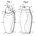
- Fig. 1 illustrates a preferred embodiment of the present invention.
- This embodiment of the dispenser includes a first and second container 2, 4 having respective first and second top ends 6, 8 and first and second bottom ends 10 , 12 .
- the top ends are open and the bottom ends are closed.
- First and second pump mechanism 14, 16 with respective dispensing nozzles 18, 20 having dispensing openings 22, 24 are positioned over the top ends of their respective containers. Openings 22, 24 of the dispensing nozzles are oriented in a direct 180° opposite one another.
- Fig. 4 and 5 best illustrate joining of the first and second containers 2, 4 along respective curvilinear surfaces 26 , 28 .
- These curvilinear surfaces are complementary-shaped to fit together along a length of the containers from top to bottom ends.
- Features of the curvilinear surfaces are best illustrated in Fig. 6 and 7.
- Curvilinear surface 26 includes a trough-shaped elongated recess 30 and an adjacent elongated ridge 32 , each bisected by a common plane P .
- Second curvilinear surface 28 also includes a trough-shaped elongated recess 34 and an adjacent elongated ridge 36 , each being bisected by a common plane P' .
- Recess 30 on the first curvilinear surface 26 snugly mates with the ridge 36 of the second curvilinear surface 28 .
- recess 34 of the second curvilinear surface mates with ridge 32 of the first curvilinear surface.
- Fig. 3 illustrates the dispenser separated into its major components.
- Top ends 6, 8 of the containers are surmounted with respective necks 38, 40 .
- Around each neck is a groove 42 with both grooves aligned forming a continuous system along an upper perimeter of the dispenser.
- a collar 44 joins together the first and second containers.
- Along a periphery of an upper edge of the collar is formed a channel 45 .
- a series of inward projecting tongues 46 are formed at a lower edge 48 of the collar. These are best viewed in Fig. 8. These tongues are engageable within groove 42 to fasten together the first and second container at their top ends.
- the collar 44 further includes a deck 50 covering an upper end thereof.
- a pair of passageways 52, 54 and downward projecting sleeves 56, 58 are formed as part of the deck.
- An annular bead 60 protrudes from an interior wall 62 of the sleeves.
- Pump mechanisms 4, 16 have respective stems 64, 66 which are inserted through the sleeves 56, 58 .
- the respective annular bead 60 forces the stems to be tightly held in place. Product leakage across the stems and through the passageways is prevented by a gasket 65 placed around each respective stem at an upper end thereof.
- Fig. 9 best illustrates a base cup 68 which snaps onto a circumferential indentation at the bottom ends 10, 12 of the joined containers.
- a pair of slightly curved ramps 72, 74 protrude upward from an inner surface of the base cup. These ramps are engageable with D-shaped indentations 73, 75 on respective bottom ends of the first and second containers.
- a pair of orienting ridges 77 are moulded on the inner surface of the base cup. The ridges are positioned opposite one another along a circumference of the base cup and each is equidistant from the respective curved ramps. These ridges are intended to fit within a small gap 81 found between surfaces 26 and 28 at a lower end of the containers.
- First and second containers and the outer surfaces of their respective pump mechanisms are coloured white and black, respectively. These colours accentuate the dual nature and purpose of the multicontainer dispenser.
- Fig. 3 illustrates overcap 76 having a closed roof 78 , an open floor 80 , a circumferential sidewall 82 and a pair of windows 84, 86 distant from one another formed into the sidewall.
- Overcap 76 shields the pump mechanisms from inadvertent activation and can snap into channel 45 formed along the upper surface of the collar 44 .
- a bead 88 along a lower margin of the overcap ensures retention of the overcap within the channel.
- the overcap is produced as a transparent plastic to sharpen a consumer awareness toward the difference between each container, and thereby the difference between the contents of each.
Abstract
Description
- The invention concerns a dual compartment pump dispenser for separately storing different compositions intended for non-simultaneous delivery.
- Multi-compartment dispensers are well known. Although expensive, there is resort to multi-compartment packaging when ingredients of a formulation are storage unstable in the presence of one another. For instance, U.S. Patent 4,871,663 (Schaeffer) and U.S. Patent 5,038,963 (Pettengill et al.) utilize dual compartment pumps for separate storage of bicarbonate and peroxide toothpaste components. The systems are intended to simultaneously dispense ribbons containing each of the active ingredients for placement onto a toothbrush. Of particular relevant to the present invention are U.S. Patent 5,158,191 and U.S. Patent 5,316,159, both to Douglas et al., describing a container with dual bottles releasably interlocked together inside-by-side relation. A single cap covers both bottles. Independently openable separate outlets for each of the bottles are formed on the cap.
- The problem sought to be solved by the present invention is delivery of two formulations in a sequential rather than simultaneous manner. One product area requiring sequential application is that of cosmetic skin treatment regimes. Two or more different compositions are employed in these regimes and applied to the skin in sequential order. These treatments may serially employ a cleanser, moisturizer, toner and finally facial foundation.
- A co-pending patent application to Suares et al., Serial No. 08/451,940, describes the need for a system to deliver actives to both prevent skin damage and also correct same. It was suggested that separate compositions be formulated for the prevent and correct segments of a treatment regime. Each of these compositions would then require respective timing for application to skin. Prevention compositions utilizing sun screens as actives would be utilized for daytime use. Correction compositions would be for nighttime use. The latter would incorporate actives such as alpha-hydroxy carboxylic acids.
- When a skin treatment regime requires multi-composition use, there have been problems with consumer education and discipline. Education is particularly a problem in mass market outlets where a cosmetic knowledgeable sales staff is generally absent. A customer may purchase one product in a treatment regime but may be uninformed with respect to a necessary complementary regime product. Even a somewhat educated customer may select the wrong complementary product. Most frustrating is when a totally educated customer discovers that the store either does not carry the complementary product or is temporarily out of stock.
- Accordingly, it is an object of the present invention is to provide a dispensing system particularly suitable for cosmetic regimes but also applicable to a wide variety of other cosmetics and products including foods, adhesives and detergents.
- It is another object of the present invention to provide a dispensing system for a multi-composition product, especially for a skin treatment regime, that ensures the recommended compositions are all provided to the consumer in a single sale.
- Still another object of the present invention is to provide a dispensing system for a product, especially a skin treatment regime, that daily serves as a remainder to the consumer as to the proper utilization of component compositions.
- Yet another object of the present invention is to provide a dispensing system for a variety of products, but especially a skin treatment regime, that maintains each of the component compositions together in a unit to avoid separation and misplacement within a consumer's home.
- A dual compartment pump dispenser is provided for storing different compositions to be delivered non-simultaneously but eventually functioning together to achieve a desired result, the dispenser including:
- (I) a first container having a top and bottom end, the top end having an opening and the bottom end being closed;
- (ii) a second container having a top and bottom end, the top end having an opening and the bottom end being closed; and
- (iii) a pair of pump mechanisms each with a dispensing nozzle having an opening for emptying product from the respective containers positioned on the top end of each container, the dispensing nozzle openings being oriented at an angle from 60° to 180° apart from one another.
- An important feature of the present invention is that the dispensing nozzle openings are oriented so that simultaneous pressing of both pump mechanisms is not suggested to a consumer. A manner for avoiding this orients the dispensing nozzle openings at an angle of at least 60° apart from one another. Preferably the openings are oriented at least 90°, most preferably 180° apart.
- Preferably the first and second containers have respective fitted together complementary shaped first and second curvilinear surfaces extending from the respective top to bottom ends. The first curvilinear surface includes a trough-shaped elongated recess and an adjacent elongated ridge, each bisected by a common plane. The second curvilinear surface likewise includes a trough-shaped elongated recess and an adjacent elongated ridge, with each likewise being bisected by a common place. When placed together the ridge of the second surface snugly mates with the recess of the first surface. Similarly the ridge of the first surface snugly mates with the recess of the second surface.
- Both pumps are fitted with dip tubes. Insertion of the dip tube into the first container requires the first curvilinear surface because of the recess to sinusoidally bulge near the top end towards the second curvilinear surface. Since the dip tube is short, there is no interference in penetrating the lower part of the first container. This permits the lower part to concavely recede away from the second curvilinear surface near the bottom end. In complementary fashion, the second curvilinear surface has a ridge in the upper part of the second container to accommodate the dip tube. This allows the second curvilinear surface near the top end to concavely recede away from the first curvilinear surface. Although primarily intended for dispensing nozzles oriented apart from one another, the aforementioned features of the curvilinear surfaces may also be employed with dispensing nozzle openings oriented parallel to one another discharging in the same direction. For this embodiment, there may be employed a mechanism for simultaneously activating both pumps. Flow of product would then proceed through a single cap with a single spray nozzle having two openings, each separately discharging contents from the respective first and second containers.
- A collar joins together the first and second container. A groove along a perimeter of the dispenser at the top end serves as an anchoring structure for a series of tongues, preferably six tongues, directed inwardly and formed on a lower edge of the collar. The arrangement of groove and tongues allows for ready removal of the pumping mechanisms from the containers. Unimpaired access to each container is thereby achieved. Remnants of product can therefore be more readily drained. Refill of product is also assisted by the removable collar arrangement.
- The collar further includes a deck covering an upper end thereof. The deck is traversed by a pair of passageways. Downwardly projecting sleeves surround each of the passageways on an undersurface of the deck. An annular bead is formed along an interior wall of each sleeve. The pumps with their respective stems are inserted through the sleeves and via the annular bead are held tightly in place.
- An overcap can be placed over the pumps. The overcap has a closed roof, an open floor, a circumferential sidewall and two windows distant from one another formed into the side walls. Preferably each of the containers and pumps are of a different colour. The preferred embodiment is for the containers to have white and black colour, respectively. The overcap is best formed of a transparent plastic. The visual aesthetics of black and white pumps is accentuated by transparency of the overcap. Nozzles of the pumps are accommodated through the windows in the overcap.
- The above features, advantages and objects of the present invention will more fully be appreciated through the following detailed discussion, reference being made to the drawings, in which:
- Fig. 1 is a front perspective view of a preferred embodiment of the dual compartment pump dispenser according to the present invention;
- Fig. 2 is a front elevational view of the dispenser according to Fig. 1;
- Fig. 3 is an exploded view of the dispenser including an overcap;
- Fig. 4 is the left hand container of the dual compartment pump dispenser shown in Fig. 2;
- Fig. 5 is the right hand container of the dual compartment pump dispenser shown in Fig. 2;
- Fig. 6 is a right side elevational view of the container in Fig. 4 showing the curvilinear surface;
- Fig. 7 is a left side elevational view of the container in Fig. 5 showing the curvilinear surface;
- Fig. 8 is a bottom view of the pump and collar assembly as seen along line 8-8 of Fig. 3; and
- Fig. 9 is a top elevational view of the base cup.
- Fig. 1 illustrates a preferred embodiment of the present invention. This embodiment of the dispenser includes a first and
second container second pump mechanism respective dispensing nozzles openings Openings - Fig. 4 and 5 best illustrate joining of the first and
second containers curvilinear surfaces 26, 28. These curvilinear surfaces are complementary-shaped to fit together along a length of the containers from top to bottom ends. Features of the curvilinear surfaces are best illustrated in Fig. 6 and 7. Curvilinear surface 26 includes a trough-shapedelongated recess 30 and an adjacentelongated ridge 32, each bisected by a common plane P. Secondcurvilinear surface 28 also includes a trough-shapedelongated recess 34 and an adjacentelongated ridge 36, each being bisected by a common plane P'.Recess 30 on the first curvilinear surface 26 snugly mates with theridge 36 of the secondcurvilinear surface 28. Likewise,recess 34 of the second curvilinear surface mates withridge 32 of the first curvilinear surface. These combinations of structures along the sinusoidal mating surfaces ensure tight fit between the pair of first and second containers. - Fig. 3 illustrates the dispenser separated into its major components. Top ends 6, 8 of the containers are surmounted with
respective necks groove 42 with both grooves aligned forming a continuous system along an upper perimeter of the dispenser. Acollar 44 joins together the first and second containers. Along a periphery of an upper edge of the collar is formed achannel 45. A series of inward projectingtongues 46 are formed at alower edge 48 of the collar. These are best viewed in Fig. 8. These tongues are engageable withingroove 42 to fasten together the first and second container at their top ends. - The
collar 44 further includes adeck 50 covering an upper end thereof. A pair ofpassageways sleeves annular bead 60 protrudes from aninterior wall 62 of the sleeves.Pump mechanisms sleeves annular bead 60 forces the stems to be tightly held in place. Product leakage across the stems and through the passageways is prevented by agasket 65 placed around each respective stem at an upper end thereof. - Fig. 9 best illustrates a
base cup 68 which snaps onto a circumferential indentation at the bottom ends 10, 12 of the joined containers. A pair of slightlycurved ramps 72, 74 protrude upward from an inner surface of the base cup. These ramps are engageable with D-shapedindentations ridges 77 are moulded on the inner surface of the base cup. The ridges are positioned opposite one another along a circumference of the base cup and each is equidistant from the respective curved ramps. These ridges are intended to fit within asmall gap 81 found betweensurfaces 26 and 28 at a lower end of the containers. - First and second containers and the outer surfaces of their respective pump mechanisms, in the preferred embodiment, are coloured white and black, respectively. These colours accentuate the dual nature and purpose of the multicontainer dispenser.
- Fig. 3 illustrates overcap 76 having a closed roof 78, an
open floor 80, acircumferential sidewall 82 and a pair ofwindows channel 45 formed along the upper surface of thecollar 44. A bead 88 along a lower margin of the overcap ensures retention of the overcap within the channel. In the preferred embodiment the overcap is produced as a transparent plastic to sharpen a consumer awareness toward the difference between each container, and thereby the difference between the contents of each. - Although the invention has been described with reference to a specific embodiment, it will be apparent to one skilled in the art that various modifications may be made thereof which fall within the scope and purview of the invention.
Claims (21)
- A dual compartment pump dispenser comprising:(I) a first container having a top and bottom end, the top end having an opening and the bottom end being closed;(ii) a second container having a top and bottom end, the top end having an opening and the bottom end being closed; and(iii) a pair of pump mechanisms each with a dispensing nozzle having an opening for emptying product from the respective containers positioned on the top end of each container, the dispensing nozzle openings being oriented at an angle from 60° to 180° apart from one another.
- A dispenser according to claim 1 wherein the first and second containers have respective complementary shaped first and second curvilinear surfaces fitted together extending from the respective top to bottom ends.
- A dispenser according to claim 2 wherein the first curvilinear surface includes a trough-shaped elongated recess and an adjacent elongated ridge each bisected by a common plane.
- A dispenser according to claim 2 or claim 3 wherein the second curvilinear surface includes a trough-shaped elongated recess and an adjacent ridge each bisected by a common plane, the ridge of the second curvilinear surface snugly mating with the recess of the first curvilinear surface.
- A dispenser according to any one of claims 2-4 wherein the first curvilinear surface sinusoidally bulges toward the second curvilinear surface near the top end and concavely recedes away from the second curvilinear surface near the bottom end.
- A dispenser according to any one of the preceding claims further comprising a collar joining together the first and second containers.
- A dispenser according to claim 6 further comprising a groove along a perimeter of the dispenser at the top end.
- A dispenser according to claim 7 wherein the collar at a lower edge thereof includes a series of inwardly projecting tongues engageable within the groove to fasten together the first and second containers.
- A dispenser according to any one of claims 6-8 wherein the collar further comprises a deck covering an upper end thereof.
- A dispenser according to claim 9 wherein the deck further comprises a pair of passageways and downward projecting sleeves with an annular bead formed along an interior wall of the sleeves.
- A dispenser according to claim 10 wherein the pump means have respective stems inserted through the sleeves and via the annular bead are tightly held in place.
- A dispenser according to any one of the preceding claims further comprising an overcap having a closed roof, an open floor, a circumferential sidewall and two windows distant from one another formed into the sidewall.
- A dispenser according to claim 12 wherein the overcap is formed of a transparent material.
- A dispenser according to any one of the preceding claims where each container is of a different colour.
- A dispenser according to claim 14 wherein one container is white and the other is black.
- A dispenser according to any one of the preceding claims further comprising a base cup having means unitarily formed therein for separately engaging the bottom end of each of the first and second containers, the base cup covering both bottom ends.
- A dual compartment pump dispenser comprising:(I) a first container having a top and bottom end, the top end having an opening and the bottom end being closed;(ii) a second container having a top and bottom end, the top end having an opening and the bottom end being closed, the first and second containers having respective complementary shaped first and second curvilinear surfaces fitted together extending from the respective to bottom ends; and(iii) a pair of pump mechanisms each with a dispensing opening for emptying product from the respective containers positioned on the top end of each container.
- A dispenser according to claim 17 wherein the first curvilinear surface includes a trough-shaped elongated recess and an adjacent elongated ridge each bisected by a common plane.
- A dispenser according to claim 18 wherein the second curvilinear surface includes a trough-shaped elongated recess and an adjacent elongated ridge each bisected by a common place, the ridge of the second curvilinear surface snugly mating with the recess of the first curvilinear surface.
- A dispenser according to claim 18 or claim 19 wherein the first curvilinear surface sinusoidally bulges toward the second curvilinear surface near the top end and concavely recedes away from the second curvilinear surface near the bottom end.
- A dispenser according to any one of claims 17-20 further comprising a base cup having means unitarily formed therein for separately engaging the bottom end of each of the first and second containers, the base cup covering both bottom ends.
Applications Claiming Priority (2)
| Application Number | Priority Date | Filing Date | Title |
|---|---|---|---|
| US645395 | 1996-05-13 | ||
| US08/645,395 US5740947A (en) | 1996-05-13 | 1996-05-13 | Dual compartment pump dispenser |
Publications (3)
| Publication Number | Publication Date |
|---|---|
| EP0807471A2 true EP0807471A2 (en) | 1997-11-19 |
| EP0807471A3 EP0807471A3 (en) | 1998-01-14 |
| EP0807471B1 EP0807471B1 (en) | 2003-01-02 |
Family
ID=24588859
Family Applications (1)
| Application Number | Title | Priority Date | Filing Date |
|---|---|---|---|
| EP97303058A Expired - Lifetime EP0807471B1 (en) | 1996-05-13 | 1997-05-02 | Dual compartment pump dispenser |
Country Status (7)
| Country | Link |
|---|---|
| US (1) | US5740947A (en) |
| EP (1) | EP0807471B1 (en) |
| JP (1) | JP3766175B2 (en) |
| CA (1) | CA2204966C (en) |
| DE (1) | DE69718096T2 (en) |
| ES (1) | ES2189925T3 (en) |
| ZA (1) | ZA974044B (en) |
Cited By (12)
| Publication number | Priority date | Publication date | Assignee | Title |
|---|---|---|---|---|
| WO2000006456A3 (en) * | 1998-07-28 | 2000-08-03 | Unilever Plc | Container and closure |
| US6223942B1 (en) | 1998-07-28 | 2001-05-01 | Lever Brothers Company, Division Of Conopco, Inc. | Container and closure |
| US6419783B1 (en) | 1999-04-16 | 2002-07-16 | Unilever Home & Personal Care Usa | Container and closure |
| DE10310947A1 (en) * | 2003-03-11 | 2004-10-07 | Schiefer, Hartmut, Prof. Dr.-Ing. | sprayer |
| WO2010049666A1 (en) * | 2008-10-31 | 2010-05-06 | Helen Jane Seward | Portable dispenser apparatus |
| FR2946230A1 (en) * | 2009-06-05 | 2010-12-10 | Audrey Bruyere | Jewel or key holder, for use on e.g. neck of user, has mono block body defining storage reservoirs of fluid products that distinct from each other, where fluid products are deodorant or liquid perfume and liquid soap |
| GB2493923A (en) * | 2011-08-21 | 2013-02-27 | Iogi Ltd | Two-Stage Deodorant Applicator |
| WO2014077840A1 (en) * | 2012-11-19 | 2014-05-22 | Colgate-Palmolive Company | Multi-chamber container |
| WO2014077843A1 (en) * | 2012-11-19 | 2014-05-22 | Colgate-Palmolive Company | Multi-chamber container |
| WO2014077842A1 (en) * | 2012-11-19 | 2014-05-22 | Colgate-Palmolive Company | Multi-chamber container |
| WO2014077844A1 (en) * | 2012-11-19 | 2014-05-22 | Colgate-Palmolive Company | Multi-chamber container |
| EP3025614A4 (en) * | 2013-07-26 | 2017-04-19 | Minjin Co., Ltd. | Cosmetic container |
Families Citing this family (53)
| Publication number | Priority date | Publication date | Assignee | Title |
|---|---|---|---|---|
| US6170708B1 (en) * | 1999-12-27 | 2001-01-09 | Tsan-Yao Chen | Dual-dispenser bottle having middle ornamental window |
| US6315171B1 (en) | 2000-09-29 | 2001-11-13 | The Plastek Group | Telescoping ram dispenser |
| JP5005125B2 (en) * | 2000-10-18 | 2012-08-22 | ホーユー株式会社 | Two-component dispenser |
| AU2002347585A1 (en) * | 2001-12-06 | 2003-06-17 | Gabriel Cabelli | Hand held fluent dispensing containers |
| JP2005520675A (en) * | 2002-03-19 | 2005-07-14 | エアースプレー インターナショナル ビー ブイ | Dispenser device |
| US7946452B2 (en) * | 2002-06-13 | 2011-05-24 | Hantman Ken S | Multiple chamber bottle with diagonal division(s) achieving curvilinear surface division(s) |
| FR2840888B1 (en) * | 2002-06-18 | 2004-09-10 | Lablabo | DEVICE FOR DISPENSING MULTIPLE FLUIDS COMPRISING AT LEAST TWO FLEXIBLE POCKETS AND TWO PUMPS |
| US20040149775A1 (en) * | 2003-01-30 | 2004-08-05 | Szu-Chang Chen | Cosmetic container having double chamber |
| WO2004103478A1 (en) * | 2003-05-20 | 2004-12-02 | Collins James F | Ophthalmic drug delivery system |
| US8012136B2 (en) * | 2003-05-20 | 2011-09-06 | Optimyst Systems, Inc. | Ophthalmic fluid delivery device and method of operation |
| US20050011853A1 (en) * | 2003-07-15 | 2005-01-20 | Gerhard Brugger | Dosing dispenser and reservoir |
| US20050098527A1 (en) * | 2003-09-15 | 2005-05-12 | Yates William M.Iii | Multiple cavity bottle and method of manufacturing same |
| ITMI20030588U1 (en) * | 2003-12-12 | 2005-06-13 | Reggiani Fulvio | CONTAINER FOR THE DISTRIBUTION OF DISTINCT PRODUCTS |
| JP3679106B1 (en) * | 2004-04-23 | 2005-08-03 | 株式会社ビー・エル・シー | Container unit |
| US7594594B2 (en) * | 2004-11-17 | 2009-09-29 | International Flavors & Fragrances Inc. | Multi-compartment storage and delivery containers and delivery system for microencapsulated fragrances |
| US20070207174A1 (en) * | 2005-05-06 | 2007-09-06 | Pluyter Johan G L | Encapsulated fragrance materials and methods for making same |
| US20070003498A1 (en) * | 2005-06-13 | 2007-01-04 | Scavone Timothy A | Assortment of antiperspirants having two or more product performance characteristics |
| US20070100657A1 (en) * | 2005-11-03 | 2007-05-03 | The Procter & Gamble Company | System of products having complimentary outer surface contours and indicia |
| CN200988015Y (en) * | 2006-10-30 | 2007-12-12 | 埃森·费尔索夫 | Sprayer |
| US20100140203A1 (en) * | 2008-12-05 | 2010-06-10 | Theodosios Kountotsis | Skeleton structure bottle with removable chambers and method of manufacturing the same |
| EP2617496B1 (en) * | 2009-06-17 | 2020-03-25 | S.C. Johnson & Son, Inc. | Handheld device for dispensing fluids |
| US8413849B2 (en) * | 2009-08-12 | 2013-04-09 | Miriam M Flores | Secure dispensing system for multiple consumables |
| US8857636B2 (en) * | 2009-11-12 | 2014-10-14 | John Lewis Sullivan | Sectional container with a detachable base and lid cover |
| EA201390121A8 (en) | 2010-07-15 | 2014-02-28 | Коринтиан Офтэлмик, Инк. | METHOD AND SYSTEM FOR PERFORMING REMOTE TREATMENT AND CONTROL |
| US10154923B2 (en) | 2010-07-15 | 2018-12-18 | Eyenovia, Inc. | Drop generating device |
| CA2805425C (en) | 2010-07-15 | 2019-07-23 | Corinthian Ophthalmic, Inc. | Ophthalmic drug delivery |
| JP5964826B2 (en) | 2010-07-15 | 2016-08-03 | アイノビア,インコーポレイティド | Drop generation device |
| US8844768B2 (en) | 2011-06-27 | 2014-09-30 | Prince Castle LLC | Liquid dispenser with storage tanks |
| WO2013090468A1 (en) | 2011-12-12 | 2013-06-20 | Corinthian Ophthalmic, Inc. | High modulus polymeric ejector mechanism, ejector device, and methods of use |
| CA2856556A1 (en) * | 2011-12-13 | 2013-06-20 | Avon Products, Inc. | Methods and compositions to impart memory effects onto biosurfaces |
| KR101343909B1 (en) * | 2012-02-29 | 2013-12-20 | (주)연우 | The pumping type cosmetic vessel having a exhaust structure of two-type materials and method thereof |
| US8870027B2 (en) * | 2012-03-15 | 2014-10-28 | David G. Kraenzle | Multi-bottle containers for dispensing measured quantities of liquids |
| US20130248538A1 (en) | 2012-03-23 | 2013-09-26 | Prince Castle, LLC | Holding Tank With Internally Reinforced Sidewalls and Liquid Dispenser Using Same |
| KR200476949Y1 (en) * | 2013-08-22 | 2015-04-20 | 펌텍코리아 (주) | A cosmetic container for sotoraging and discharging two contents |
| TW201536639A (en) * | 2014-03-21 | 2015-10-01 | Canamerica Llc | Supply container and fluid supply assembly |
| US9565978B2 (en) * | 2014-04-07 | 2017-02-14 | Dominick Hall | Multiple dispensing assembly |
| FR3019532B1 (en) * | 2014-04-08 | 2017-10-06 | Qualipac Sa | BOTTLE, SYSTEM COMPRISING SUCH BOTTLE AND METHOD FOR MANUFACTURING THE SAME |
| KR101446612B1 (en) * | 2014-05-26 | 2014-10-06 | (주)민진 | Cosmetic vessel |
| US10435831B1 (en) * | 2014-07-15 | 2019-10-08 | Rita Harry-Ogiste | Fabric treating accessories and associated use thereof |
| US10307779B2 (en) | 2015-05-01 | 2019-06-04 | St&T Packaging Pte. Ltd. | Dual-chambered bottles for storing and dispensing of fluid and semi-fluid materials |
| KR200482260Y1 (en) * | 2015-05-22 | 2017-01-04 | 동국대학교 산학협력단 | Container for selectively exhausting medicine |
| US9926104B2 (en) | 2015-07-28 | 2018-03-27 | Stackcan Llc | Container system and apparatus |
| TWI577310B (en) * | 2016-03-25 | 2017-04-11 | Multi-stage liquid quantitative supply container | |
| KR101972213B1 (en) * | 2017-05-12 | 2019-04-24 | 강성일 | Receptacle for separately keeping and mixed use of different materials |
| KR20240034855A (en) | 2017-06-10 | 2024-03-14 | 아이노비아 인코포레이티드 | Methods and devices for handling a fluid and delivering the fluid to the eye |
| CN112334119A (en) | 2018-06-29 | 2021-02-05 | 宝洁公司 | Two-phase product |
| JP7148646B2 (en) | 2018-06-29 | 2022-10-05 | ザ プロクター アンド ギャンブル カンパニー | Two-phase product |
| US11583479B2 (en) | 2018-06-29 | 2023-02-21 | The Procter & Gamble Company | Dual phase products |
| CN109781744A (en) * | 2019-03-04 | 2019-05-21 | 苏州热工研究院有限公司 | A kind of infiltration spray cans |
| JP7315727B2 (en) | 2019-07-09 | 2023-07-26 | ザ プロクター アンド ギャンブル カンパニー | Multi-composition product dispenser |
| EP3996852A1 (en) | 2019-07-09 | 2022-05-18 | The Procter & Gamble Company | Multi-component product dispenser |
| DE102020118422A1 (en) | 2020-07-13 | 2022-01-13 | Bayerische Motoren Werke Aktiengesellschaft | Fragrance and disinfectant dispensers in the vehicle |
| US20220324612A1 (en) * | 2021-04-12 | 2022-10-13 | Adel A. Awad | Separable container |
Citations (7)
| Publication number | Priority date | Publication date | Assignee | Title |
|---|---|---|---|---|
| US3269605A (en) * | 1965-08-03 | 1966-08-30 | Aaron S Tesler | Pressurized dispenser assembly having a plurality of individual chambers |
| US3269389A (en) * | 1963-03-11 | 1966-08-30 | Bernard L Meurer | Compartmental dispensing container for nose and throat preparations |
| EP0443519A2 (en) * | 1990-02-20 | 1991-08-28 | Michael Feldmann | Device for discharging a fluid |
| EP0479451A2 (en) * | 1990-10-01 | 1992-04-08 | Take 5 | Hand operated sprayer with multiple fluid containers |
| JPH06191556A (en) * | 1992-12-26 | 1994-07-12 | Komatsu Ltd | Container with pump for a plurality of liquids |
| WO1995000436A1 (en) * | 1993-06-22 | 1995-01-05 | Nottingham-Spirk Design Associates, Inc. | Dual chamber sprayer with metering assembly |
| WO1996037420A1 (en) * | 1995-05-26 | 1996-11-28 | Unilever Plc | Treatment regime for skin |
Family Cites Families (13)
| Publication number | Priority date | Publication date | Assignee | Title |
|---|---|---|---|---|
| US3187757A (en) * | 1962-12-17 | 1965-06-08 | J & J Casting Inc | Plural dispensing units and toilet kit with central compartmented storage member |
| DE3142205A1 (en) * | 1981-10-24 | 1983-05-05 | Daubner, Annette | Multi-spray can |
| US4687663B1 (en) * | 1983-03-01 | 1997-10-07 | Chesebrough Ponds Usa Co | Dental preparation article and method for storage and delivery thereof |
| DE3614515A1 (en) * | 1986-04-29 | 1987-11-05 | Pfeiffer Erich Gmbh & Co Kg | DISCHARGE DEVICE FOR MEDIA |
| JPH0210271U (en) * | 1988-06-20 | 1990-01-23 | ||
| US5020694A (en) * | 1989-03-16 | 1991-06-04 | Chesebrough-Pond's, Inc. | Multi-cavity dispensing container |
| DE3911089A1 (en) * | 1989-04-06 | 1990-10-25 | Heitland Und Petre Int Gmbh | Metering device |
| JP2533920Y2 (en) * | 1991-02-01 | 1997-04-30 | 鐘紡株式会社 | Liquid mixing and discharging device for aerosol containers |
| US5158191A (en) * | 1991-03-01 | 1992-10-27 | Plastic Processing Corporation | Dual bottle container having a dual outlet cap |
| US5316159A (en) * | 1991-03-01 | 1994-05-31 | Plastic Processing Corporation | Dual bottle container |
| JPH0516681U (en) * | 1991-08-07 | 1993-03-02 | 恵一郎 秋葉 | Multifunctional aerosol sprayer |
| US5252312A (en) * | 1992-09-30 | 1993-10-12 | Chesebrough-Pond's Usa Co., Division Of Conopco, Inc. | Package effervescible composition |
| NL9301506A (en) * | 1993-09-01 | 1995-04-03 | Cornelis Elizabeth Rijlaarsdam | Container assembly with at least two containers |
-
1996
- 1996-05-13 US US08/645,395 patent/US5740947A/en not_active Expired - Lifetime
-
1997
- 1997-05-02 EP EP97303058A patent/EP0807471B1/en not_active Expired - Lifetime
- 1997-05-02 ES ES97303058T patent/ES2189925T3/en not_active Expired - Lifetime
- 1997-05-02 DE DE69718096T patent/DE69718096T2/en not_active Expired - Lifetime
- 1997-05-09 ZA ZA974044A patent/ZA974044B/en unknown
- 1997-05-09 CA CA002204966A patent/CA2204966C/en not_active Expired - Fee Related
- 1997-05-13 JP JP12262397A patent/JP3766175B2/en not_active Expired - Fee Related
Patent Citations (7)
| Publication number | Priority date | Publication date | Assignee | Title |
|---|---|---|---|---|
| US3269389A (en) * | 1963-03-11 | 1966-08-30 | Bernard L Meurer | Compartmental dispensing container for nose and throat preparations |
| US3269605A (en) * | 1965-08-03 | 1966-08-30 | Aaron S Tesler | Pressurized dispenser assembly having a plurality of individual chambers |
| EP0443519A2 (en) * | 1990-02-20 | 1991-08-28 | Michael Feldmann | Device for discharging a fluid |
| EP0479451A2 (en) * | 1990-10-01 | 1992-04-08 | Take 5 | Hand operated sprayer with multiple fluid containers |
| JPH06191556A (en) * | 1992-12-26 | 1994-07-12 | Komatsu Ltd | Container with pump for a plurality of liquids |
| WO1995000436A1 (en) * | 1993-06-22 | 1995-01-05 | Nottingham-Spirk Design Associates, Inc. | Dual chamber sprayer with metering assembly |
| WO1996037420A1 (en) * | 1995-05-26 | 1996-11-28 | Unilever Plc | Treatment regime for skin |
Non-Patent Citations (1)
| Title |
|---|
| PATENT ABSTRACTS OF JAPAN vol. 018, no. 544 (M-1688), 18 October 1994 & JP 06 191556 A (KOMATSU LTD), 12 July 1994, * |
Cited By (12)
| Publication number | Priority date | Publication date | Assignee | Title |
|---|---|---|---|---|
| WO2000006456A3 (en) * | 1998-07-28 | 2000-08-03 | Unilever Plc | Container and closure |
| US6223942B1 (en) | 1998-07-28 | 2001-05-01 | Lever Brothers Company, Division Of Conopco, Inc. | Container and closure |
| US6419783B1 (en) | 1999-04-16 | 2002-07-16 | Unilever Home & Personal Care Usa | Container and closure |
| DE10310947A1 (en) * | 2003-03-11 | 2004-10-07 | Schiefer, Hartmut, Prof. Dr.-Ing. | sprayer |
| WO2010049666A1 (en) * | 2008-10-31 | 2010-05-06 | Helen Jane Seward | Portable dispenser apparatus |
| FR2946230A1 (en) * | 2009-06-05 | 2010-12-10 | Audrey Bruyere | Jewel or key holder, for use on e.g. neck of user, has mono block body defining storage reservoirs of fluid products that distinct from each other, where fluid products are deodorant or liquid perfume and liquid soap |
| GB2493923A (en) * | 2011-08-21 | 2013-02-27 | Iogi Ltd | Two-Stage Deodorant Applicator |
| WO2014077840A1 (en) * | 2012-11-19 | 2014-05-22 | Colgate-Palmolive Company | Multi-chamber container |
| WO2014077843A1 (en) * | 2012-11-19 | 2014-05-22 | Colgate-Palmolive Company | Multi-chamber container |
| WO2014077842A1 (en) * | 2012-11-19 | 2014-05-22 | Colgate-Palmolive Company | Multi-chamber container |
| WO2014077844A1 (en) * | 2012-11-19 | 2014-05-22 | Colgate-Palmolive Company | Multi-chamber container |
| EP3025614A4 (en) * | 2013-07-26 | 2017-04-19 | Minjin Co., Ltd. | Cosmetic container |
Also Published As
| Publication number | Publication date |
|---|---|
| ES2189925T3 (en) | 2003-07-16 |
| DE69718096D1 (en) | 2003-02-06 |
| DE69718096T2 (en) | 2003-08-21 |
| EP0807471A3 (en) | 1998-01-14 |
| CA2204966C (en) | 2006-09-19 |
| JP3766175B2 (en) | 2006-04-12 |
| JPH1053290A (en) | 1998-02-24 |
| ZA974044B (en) | 1998-11-09 |
| US5740947A (en) | 1998-04-21 |
| EP0807471B1 (en) | 2003-01-02 |
| CA2204966A1 (en) | 1997-11-13 |
Similar Documents
| Publication | Publication Date | Title |
|---|---|---|
| EP0807471B1 (en) | Dual compartment pump dispenser | |
| EP0705202B1 (en) | Dual chamber dispenser | |
| US6276853B1 (en) | Axially aligned, commonly joined dual dispensers | |
| US5954213A (en) | Dual container and individual chamber therefor | |
| US20130134161A1 (en) | Dual compartment package for dispensing fluids | |
| US8857636B2 (en) | Sectional container with a detachable base and lid cover | |
| US4767034A (en) | Scrubber cap closure | |
| EP1954576B1 (en) | Bottle and cup/lid combination | |
| US6910573B2 (en) | Dual container bottle | |
| US20110036867A1 (en) | Secure dispensing system for multiple consumables | |
| US20030205584A1 (en) | Dispensing pouch | |
| US6923347B2 (en) | Assembly for packaging a product, especially a cosmetic product | |
| US20010030203A1 (en) | Soap dispensing container | |
| US20020036212A1 (en) | Dispensing device and methods | |
| CA2247118A1 (en) | Double-ended perfume bottle | |
| WO1999037190A1 (en) | Bottle convertible into drinking utensil | |
| US20090014457A1 (en) | Hermetic container system | |
| JP3650583B2 (en) | Mechanical twist dispenser | |
| HU216533B (en) | Squeeze tube and removable closure | |
| US20210292074A1 (en) | Connected Dispenser System | |
| WO2013013310A1 (en) | Container for dispensing liquid | |
| US7125187B2 (en) | Closure system for a container | |
| US6345733B1 (en) | Dual compartment package | |
| KR200203011Y1 (en) | A muti-vessel | |
| US20100149905A1 (en) | Multi-chamber mixing cup |
Legal Events
| Date | Code | Title | Description |
|---|---|---|---|
| PUAI | Public reference made under article 153(3) epc to a published international application that has entered the european phase |
Free format text: ORIGINAL CODE: 0009012 |
|
| AK | Designated contracting states |
Kind code of ref document: A2 Designated state(s): DE ES FR GB IT |
|
| PUAL | Search report despatched |
Free format text: ORIGINAL CODE: 0009013 |
|
| AK | Designated contracting states |
Kind code of ref document: A3 Designated state(s): DE ES FR GB IT |
|
| 17P | Request for examination filed |
Effective date: 19980525 |
|
| 17Q | First examination report despatched |
Effective date: 20010515 |
|
| GRAH | Despatch of communication of intention to grant a patent |
Free format text: ORIGINAL CODE: EPIDOS IGRA |
|
| GRAH | Despatch of communication of intention to grant a patent |
Free format text: ORIGINAL CODE: EPIDOS IGRA |
|
| GRAA | (expected) grant |
Free format text: ORIGINAL CODE: 0009210 |
|
| AK | Designated contracting states |
Kind code of ref document: B1 Designated state(s): DE ES FR GB IT |
|
| REG | Reference to a national code |
Ref country code: GB Ref legal event code: FG4D Free format text: 20030102 |
|
| REF | Corresponds to: |
Ref document number: 69718096 Country of ref document: DE Date of ref document: 20030206 Kind code of ref document: P |
|
| ET | Fr: translation filed | ||
| REG | Reference to a national code |
Ref country code: ES Ref legal event code: FG2A Ref document number: 2189925 Country of ref document: ES Kind code of ref document: T3 |
|
| PLBE | No opposition filed within time limit |
Free format text: ORIGINAL CODE: 0009261 |
|
| STAA | Information on the status of an ep patent application or granted ep patent |
Free format text: STATUS: NO OPPOSITION FILED WITHIN TIME LIMIT |
|
| 26N | No opposition filed |
Effective date: 20031003 |
|
| PGFP | Annual fee paid to national office [announced via postgrant information from national office to epo] |
Ref country code: ES Payment date: 20110526 Year of fee payment: 15 Ref country code: FR Payment date: 20110607 Year of fee payment: 15 |
|
| PGFP | Annual fee paid to national office [announced via postgrant information from national office to epo] |
Ref country code: GB Payment date: 20110525 Year of fee payment: 15 |
|
| PGFP | Annual fee paid to national office [announced via postgrant information from national office to epo] |
Ref country code: DE Payment date: 20110527 Year of fee payment: 15 Ref country code: IT Payment date: 20110526 Year of fee payment: 15 |
|
| GBPC | Gb: european patent ceased through non-payment of renewal fee |
Effective date: 20120502 |
|
| PG25 | Lapsed in a contracting state [announced via postgrant information from national office to epo] |
Ref country code: IT Free format text: LAPSE BECAUSE OF NON-PAYMENT OF DUE FEES Effective date: 20120502 |
|
| REG | Reference to a national code |
Ref country code: FR Ref legal event code: ST Effective date: 20130131 |
|
| REG | Reference to a national code |
Ref country code: DE Ref legal event code: R119 Ref document number: 69718096 Country of ref document: DE Effective date: 20121201 |
|
| PG25 | Lapsed in a contracting state [announced via postgrant information from national office to epo] |
Ref country code: FR Free format text: LAPSE BECAUSE OF NON-PAYMENT OF DUE FEES Effective date: 20120531 Ref country code: GB Free format text: LAPSE BECAUSE OF NON-PAYMENT OF DUE FEES Effective date: 20120502 |
|
| PG25 | Lapsed in a contracting state [announced via postgrant information from national office to epo] |
Ref country code: DE Free format text: LAPSE BECAUSE OF NON-PAYMENT OF DUE FEES Effective date: 20121201 |
|
| REG | Reference to a national code |
Ref country code: ES Ref legal event code: FD2A Effective date: 20130820 |
|
| PG25 | Lapsed in a contracting state [announced via postgrant information from national office to epo] |
Ref country code: ES Free format text: LAPSE BECAUSE OF NON-PAYMENT OF DUE FEES Effective date: 20120503 |