EP0808601A2 - Cleaning implement, in particular for wet wiping - Google Patents
Cleaning implement, in particular for wet wiping Download PDFInfo
- Publication number
- EP0808601A2 EP0808601A2 EP97107936A EP97107936A EP0808601A2 EP 0808601 A2 EP0808601 A2 EP 0808601A2 EP 97107936 A EP97107936 A EP 97107936A EP 97107936 A EP97107936 A EP 97107936A EP 0808601 A2 EP0808601 A2 EP 0808601A2
- Authority
- EP
- European Patent Office
- Prior art keywords
- cleaning
- wiper plate
- cleaning element
- fabric
- base fabric
- Prior art date
- Legal status (The legal status is an assumption and is not a legal conclusion. Google has not performed a legal analysis and makes no representation as to the accuracy of the status listed.)
- Granted
Links
Images


Classifications
-
- A—HUMAN NECESSITIES
- A47—FURNITURE; DOMESTIC ARTICLES OR APPLIANCES; COFFEE MILLS; SPICE MILLS; SUCTION CLEANERS IN GENERAL
- A47L—DOMESTIC WASHING OR CLEANING; SUCTION CLEANERS IN GENERAL
- A47L13/00—Implements for cleaning floors, carpets, furniture, walls, or wall coverings
- A47L13/10—Scrubbing; Scouring; Cleaning; Polishing
- A47L13/20—Mops
- A47L13/24—Frames for mops; Mop heads
- A47L13/254—Plate frames
- A47L13/256—Plate frames for mops made of cloth
-
- A—HUMAN NECESSITIES
- A47—FURNITURE; DOMESTIC ARTICLES OR APPLIANCES; COFFEE MILLS; SPICE MILLS; SUCTION CLEANERS IN GENERAL
- A47L—DOMESTIC WASHING OR CLEANING; SUCTION CLEANERS IN GENERAL
- A47L13/00—Implements for cleaning floors, carpets, furniture, walls, or wall coverings
- A47L13/10—Scrubbing; Scouring; Cleaning; Polishing
- A47L13/42—Details
- A47L13/46—Securing scouring or polishing cloths or sponges to the handles by gripping means, tongs, or the like
-
- A—HUMAN NECESSITIES
- A47—FURNITURE; DOMESTIC ARTICLES OR APPLIANCES; COFFEE MILLS; SPICE MILLS; SUCTION CLEANERS IN GENERAL
- A47L—DOMESTIC WASHING OR CLEANING; SUCTION CLEANERS IN GENERAL
- A47L13/00—Implements for cleaning floors, carpets, furniture, walls, or wall coverings
- A47L13/10—Scrubbing; Scouring; Cleaning; Polishing
- A47L13/50—Auxiliary implements
- A47L13/58—Wringers for scouring pads, mops, or the like, combined with buckets
Definitions
- the present invention relates to a cleaning device, in particular for wet and wet wiping, with a support group which has a handle and a wiping plate, and with a cleaning element which can be fastened to a wiping plate to form at least one connecting region in such a way that it is at least partially separated from it is pivotable away.
- a cleaning element of a mop consists, for example, of a multiplicity of absorbent fabric strips or a multiplicity of absorbent yarns, which are fastened together at the end of a broomstick.
- the dampened fabric strips or yarns bind soil dirt when they are moved over a floor to be cleaned. After cleaning the floor, the fabric strips or the yarns are immersed in clean cleaning liquid such as cleaning water and rinsed out.
- the German utility model G 84 17 307.6 discloses a hollow sieve to be placed on a commercially available cleaning bucket, into which a mop can be inserted, the fabric strips of which have soaked with cleaning liquid.
- the user of the mop exerts a pressure from above by pressing the handle of the mop into the hollow screen onto the fabric strips, so that they are pressed together in the hollow screen.
- the cleaning liquid contained in the fabric strips pressed out so that it can flow into the bucket provided under the hollow sieve.
- This solution has the disadvantage that a large force is required to squeeze out the fabric strips of the mop. Furthermore, there is always the risk of disadvantageous deformation of the hollow screen or the undesired knocking over of the cleaning bucket.
- a further development of the aforementioned hollow sieve whereby according to this further development the force required to express the fabric strips of the mop is reduced.
- a hollow screen is provided, which can be deformed transversely to the pressing direction as a result of the force acting when the fabric strips are pressed into the hollow screen, reducing its clear width and compressing the fabric strips of the mop.
- the pressing force acting in the pressing-in direction of the mop is also converted into a component acting laterally on the fabric strips of the mop.
- a disadvantage of the aforementioned hollow screen is that it is particularly susceptible to malfunctions due to its additional mobility. So it often happens that the hollow sieve is pressed through a holder essential for the compression.
- the hollow sieve frequently gets stuck to the tissue strips of the mop after pulling out the fabric strips of the mop and subsequently falls into the bucket for the cleaning liquid provided under the hollow sieve.
- the two aforementioned malfunctions restrict the suitability of the known wet wiping system to a considerable extent.
- a generic cleaning device has a support group or a mop holder which has a handle or a handle and a wiper plate.
- the wiper plate is divided in the middle in the area of the attachment of the handle in such a way that two jointly movable wiper plate halves are formed which fold down like wings when the support group is lifted.
- a flat cleaning element or a mop cover is attached to each outer end of a wiper plate half that points away from the common center.
- the wiper plate halves of the wiper plate collapse along their movable center line, so that the cleaning element is carried only by the fabric strips provided at the ends of the wiper plate half, forming an arc from the ends of the Wiper plate halves hanging down.
- the cleaning element can be inserted into a lever press, wherein the cleaning liquid present in the cleaning element can subsequently be squeezed out.
- the generic cleaning device is particularly disadvantageous that an expensive and space-consuming lever press must be available for pressing out the cleaning element.
- Another disadvantage is that the cleaning element must be attached to the wiper plate in a cumbersome manner.
- the structure of the generic cleaning device is also complicated, so that its operation is cumbersome.
- the wiper plate has a contact surface in at least one holding area, which is designed such that the cleaning element can be compressed between the contact surface and at least one counter surface when pivoted away from the wiper plate.
- the cleaning element configured as mentioned above, it is particularly easy to squeeze out the cleaning liquid contained in the cleaning element, which in particular has a sponge, a tissue, such as cloths or rags, yarns or by bundles of the aforementioned cleaning elements.
- the invention is based on the idea that the force applied by the user of the cleaning device can be converted particularly effectively into a pressing force for pressing out the cleaning element by means of a special contact surface.
- the counter surface is in particular formed by another object, such as through the bottom of a bucket or through a hollow sieve known in the prior art. Furthermore, it is conceivable that the counter surface is itself formed by the floor surface to be cleaned.
- the cleaning element provided on the device configured as mentioned above can be pressed out in a particularly simple and easy manner, the pressing out being particularly easy to start when the contact surface is arranged substantially perpendicular to the surface of the wiper plate facing the cleaning element and is just trained.
- an inclined arrangement of the contact surface with respect to the surface of the wiper plate is also possible.
- a clamping device is designed to fasten the cleaning element to the wiper plate, the clamping device being able to have a releasable clamping strip which interacts with a counter strip.
- the cleaning element can be fastened in a particularly simple manner between a detachable clamping strip and a counter strip by inserting it between the clamping strip and the clamping strip detached therefrom, whereupon the cleaning element is clamped between the clamping strip and counter strip.
- the clamping bar is pivotally articulated on the counter bar, at least one locking device for the releasable connection of the clamping and Counter bar is provided, which can also be designed as a snap connection or as a hook connection. This considerably simplifies the operation of the clamping device.
- the cleaning device according to the invention can be operated more easily if the support group additionally has a connecting element for connecting the handle and the wiper plate, the connecting element in particular being able to have a joint which can be pivoted in one plane.
- the joint can also be pivotable in two planes, as is the case when the joint is designed as a double joint.
- a particularly simple operation of the cleaning device according to the invention results when the joint is arranged in the area of the center of gravity of the wiper plate, it being particularly advantageous if the joint is arranged such that the wiper plate is raised when the handle is raised and when the wiper plate is pivoted away State of the cleaning element is substantially between the handle and cleaning element. In this state, the cleaning element is at the bottom, while essentially only the wiper plate extends between the handle and the cleaning element.
- the cleaning element located under the wiping plate can be quickly pressed together, whereby simple operation and effective pressing out of the cleaning element is achieved without the cleaning element having to be touched by hand.
- a fastening assembly is provided in the connecting element with which the handle can be attached. This can be achieved, for example, by means of a screw thread, a clamp connection or a transverse bore with a pin which can be fastened in a broom handle in particular.
- a particularly advantageous embodiment of the wiper plate has an essentially trapezoidal outline.
- a cleaning device with a wiper plate with the aforementioned layout is suitable for easy and precise cleaning of hidden surfaces. It increases the stability of the cleaning device according to the invention when the Wiper plate on its side facing away from the cleaning element has stiffening elements, in particular in the form of stiffening ribs.
- a wiper plate designed as mentioned above can be manufactured particularly easily from plastic.
- a cleaning element according to the invention in particular a mop cover, which is intended in particular for use in a cleaning device according to one of claims 1 to 22, has an essentially flat base fabric and a cleaning fabric provided on one side of the base fabric, both a base fabric section with cleaning fabric and a Basic fabric section without cleaning fabric is provided.
- the base fabric section which has no cleaning fabric, can be easily attached to the wiper plate due to its smaller thickness and because of its greater flexibility, especially if it has a clamping device according to the invention.
- the base fabric section with cleaning fabric can be designed as a pile fabric, the pile fabric having a pile with a pile length between 5 mm and 20 mm.
- the base fabric section with cleaning fabric can also have a fabric with tufted loops, it also being possible to provide a fabric with sewn-on fringe and / or loop webs.
- the aforementioned fabrics have particularly good cleaning properties, and cleaning-active textile fibers can also be used. These fibers can consist of natural fibers, such as cotton or viscose, or also of synthetic fibers, such as polyester or polyamide, or of combinations of the aforementioned types of fibers.
- the cleaning fabric according to the invention has in particular a section with a trapezoidal outline, which simplifies the cleaning of even hard-to-reach places.
- the cleaning element according to the invention can also have a section with a square outline, which can merge into an area which is designed such that the cleaning element in this area has a basic fabric section without cleaning fabric, with which the cleaning element, as already explained above, is particularly simple and reliable a clamping device can be attached. This enables simple handling of the cleaning element according to the invention and, in particular, secure attachment in the cleaning device according to the invention.
- the cleaning element can be pressed out in a particularly simple manner, with the cleaning device according to the invention making it possible to clean floors reliably and quickly.
- a secure connection of the squeeze basket with the container for the cleaning liquid is obtained when the squeeze basket has contact surfaces with hooks that can be hooked under the edge of a bucket. This counteracts an overturning of the bucket due to a careless movement of the user of the cleaning system according to the invention when the cleaning element is pressed out.
- the inventive method for pressing out the cleaning element achieves simple and reliable separation of the cleaning liquid present in the cleaning element.
- the cleaning device in particular for wet and wet wiping, has a supporting group with a handle and with a wiper plate and a cleaning element which can be connected to the wiper plate to form at least two connecting areas, wiper plate and the cleaning element are designed such that the cleaning element can be fastened to the wiper plate in at least a first connecting area such that they can be pivoted relative to one another, and the cleaning element and the wiping plate are designed in at least one second connecting area so that they are there on the wiper plate pivoted state of the cleaning element in the direction of the surface of the wiper plate facing the cleaning element together form a coherent connection, while in a direction transverse to the aforementioned surface, in particular in the sense of each other are flexible that it is possible to separate them in a simple manner.
- This special design of the cleaning device according to the invention ensures that the cleaning element is pivotally connected to the wiper plate in a first region, while the wiper plate in another region of the cleaning element is not firmly connected to the wiper plate, but in particular can only be brought into engagement with it .
- the condition in which the cleaning element is firmly engaged with the wiper plate is preferably present when the cleaning device according to the invention is in the cleaning position on a floor surface. Then it is ensured by the formation of the wiper plate and cleaning element that the cleaning element cannot move transversely to the surface of the wiper plate in the region in which the wiper plate engages with the cleaning element. This enables the cleaning element to be guided precisely on the floor to be cleaned.
- the cleaning element and wiper plate When the wiper plate is lifted from the floor surface to be cleaned, the cleaning element and wiper plate preferably detach themselves from one another, so that the cleaning element hanging freely from the wiper plate downward for pressing out the cleaning fluid stored in it can be used in a corresponding device without it as in wiping systems known in the prior art would have to be removed from the wiping plate. This avoids an expensive attachment of the cleaning element to the wiper plate while nevertheless, the cleaning element can be easily cleaned without having to touch it by hand.
- a particularly reliable function of the cleaning device according to the invention is obtained if a clamping device is designed to fasten the cleaning element to the wiper plate.
- This clamping device can be developed in particular in accordance with one of the claims 5 to 11 described above.
- the cleaning element has a base fabric and a cleaning fabric provided on the base fabric, both a base fabric section with cleaning fabric and a base fabric section without cleaning fabric being provided on both sides of the base fabric.
- the cleaning element has a base fabric and a cleaning fabric provided on the base fabric, both a base fabric section with cleaning fabric and a base fabric section without cleaning fabric being provided on both sides of the base fabric.
- the aforementioned design of the cleaning element also ensures that there is a coherent connection of the cleaning element with the wiper plate when the cleaning element is pivoted to the wiper plate, since the cleaning fabric provided on the base fabric then counteracts a lateral movement of the wiper plate. This counteracts a displacement of the wiper plate and cleaning element, so that the cleaning device according to the invention is easier to handle.
- the cleaning element is designed such that when the cleaning element is fastened in the clamping device and pivoted onto the wiper plate, the surface of the wiper plate facing the cleaning element is in contact with the cleaning fabric. Then the cleaning fabric located under the wiper plate is pressed together on the base fabric, while the upright cleaning fabric located next to it counteracts a lateral displacement of the wiper plate.
- the cleaning device according to the invention designed as above can be designed in accordance with claims 12 to 30 with regard to the connection of handle and wiper plate, with regard to the design of the wiper plate and with regard to the design of the cleaning element. It is also possible to use a cleaning device to provide, which in addition to the features of claims 34 to 39 also includes the features of claims 1 to 3. Such a cleaning device according to the invention combines the advantages of easy pressing out of the cleaning element with the advantages of easy handling during cleaning and when moving into a state before the cleaning element is pressed out.
- a cleaning element according to the invention can be produced particularly simply and inexpensively, the function in the cleaning device according to the invention and in the cleaning system according to the invention being ensured.
- a particularly wear-resistant cleaning element can be achieved if at least one binding tape and / or at least one binding seam are provided on the edges of the cleaning element during the course of production.
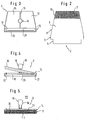
- Figure 1 shows a wiper device 1 according to the invention in side view.
- the mopping device 1 has a mop 2 which is carried by a mop holder 3. In the view shown in FIG. 1, the mop 2 lies on the surface 4 of a floor 5 to be cleaned.
- the mop 2 has a carrier fabric 6 to which a cleaning fabric 7 with tufted loops is applied on one side.
- the mop 2 is essentially divided into three areas. In a cleaning area 8, the cleaning fabric 7 is in contact with the surface 4 of the floor 5.
- a fastening area 9 of the mop 2 is provided, in which the mop 2 is connected to the mop holder 3.
- a contact area 10 of the mop 2 is also provided, in which the mop 2 has a double layer of base fabric 6 with cleaning fabric 7 and therefore also on its side facing away from the surface 4, cleaning fabric 7.
- the mop 2 is also connected to the mop holder 3 in the contact area 10.
- the mop 2 has an essentially trapezoidal outline, the narrower side of the trapezoid being provided on the side of the mop 2 facing away from the fastening region 9.
- the carrier fabric 6 is turned over and connected to the underside by gluing.
- cleaning fabric 7 is also provided in the contact area 10 on the top of the mop 2, which can be seen particularly well in this illustration.
- the fastening area 9 itself lying opposite the contact area 10 has a square outline.
- an edge strip cleaning area 11 which can be seen particularly well in this view, is provided, which also has a square outline.
- the mop holder 3 as can best be seen in FIG. 1 and in FIG. 3, has a wiper plate 12 which is provided with a rib 13 over part of its length.
- the wiper plate 12 is just large enough that the mop 2 protrudes in the operational state beyond the edges of the wiper plate 12.
- a clamping device 14 is provided on the wiper plate 12 with a counter strip 15 on the wiper plate side and a clamping strip 16 which is pivotably attached to the latter.
- the clamping device 14 is designed such that the fastening area 9 of the mop 2 can be firmly received in it.
- a handle holder 18 is pivotally attached via a pivot pin 17, which has a round receptacle 19 on its side facing away from the wiper plate 12 for receiving a handle 20.
- Fastening elements (not shown) for connecting the handle holder 19 and the handle 20 are also provided in this view.
- the clamping strip 16 which is pivotably attached to the counter strip 15 by a pivot pin 21, can be pivoted away from the counter strip 15 after a snap connection 22 has been released, so that the fastening region 9 of the mop 2 between Counter bar 15 and terminal block 16 can be inserted.
- the fastening area 9 of the mop 2 is inserted between the counter bar 15 and the clamping bar 16 until the edge bar cleaning area 11 of the mop 2 rests against the front edge of the clamping device 14, as can best be seen in FIG. 1 and in FIG. 5.
- both the counter bar 15 and the terminal block 16 are W-shaped in cross section.
- Mating bar 15 and clamping bar 16 are further designed so that they form a flat pressing surface 23 in abutting condition on their side facing away from the wiper plate 12, which is perpendicular to the lower surface of the wiper plate 12 facing the mop 2.
- the wiper plate 12 is also designed so that the handle 20 together with the handle holder 18 can be pivoted so far in the direction away from the clamping device 14 that the handle holder 18 rests on the top of the wiper plate 12.
- the wiper 1 is shown in three positions “I", “II” and “III".
- the view “I” shows the mopping device 1 after it has been placed on the floor 5 such that the mop 2 lies almost completely on the surface 4 of the floor while the mop holder 3 is not yet touching the top of the mop 2.
- the position “II” shows an intermediate state of the mop holder 3 on the way from state “I” to state “III”.
- state “III" which is also shown in FIG. 5
- the mop holder 3 is completely placed on the upper surface of the mop 2.
- the special type of fastening of the mop 2 in the clamping device 14 ensures that the edge strip cleaning area 11 of the mop 2 is located in the area of the pressing surface 23.
- this pressing surface 23 is perpendicular to the surface 4 of the base 5, which ensures that the edge strip cleaning area 11 of the mop 3 located above the pressing surface 23 is simple any edge strips of a wall not shown in the figures can be cleaned in the area of the base 5.
- FIG. 6, FIG. 7 and FIG. 8 show an extrusion basket 30 belonging to the wiper device 1, which is placed on a commercially available bucket 31.
- the squeezing basket 30 is made of plastic, and squeezing baskets of metal such as steel or aluminum, not shown in this view, are also provided.
- the squeeze basket 30 has a support surface 32 with hooks 33 on both sides, which include a bucket edge 34.
- the contact surfaces 32 and the hooks 33 are designed in such a way that the squeeze basket 30 can be placed on buckets with different diameters.
- the squeeze basket 30 has a funnel-shaped immersion opening 35 and runs slightly conically from the immersion opening 35 to a basket base 36.
- Side walls 37 are perforated with vertically extending grooves 38, while a plurality of drain holes 39 are made in the basket base 36.
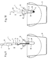
- the squeezing of the mop 2 in the squeeze basket 30 can best be seen in FIGS. 9 and 10.
- the mopping device 1 lifted off the floor with the mop holder 3 folded down and with the mop holder 2 adjoining the mop holder 3 is brought over the squeeze basket 30 and inserted into the immersion opening 35 from above, which is designated in FIG. 9 with the state “IV” .
- the wiping device 1 is pressed further into the squeeze basket 30 using a force F, so that the mop 2 folds like a fold.
- the mop 2 With the flat pressing surface 23, the mop 2 is now pressed together by pressure from above such that a cleaning liquid contained in the mop 2 can run through the grooves 38 in the side walls 37 into the bucket 31, as indicated in FIG. 10 with the state "V” .
- the relatively small pressing surface 23 results in a high pressure under the application of the force F and thus a squeezing result which is comparable to the manual wringing out of the mop 2.
- the squeezing basket 30 is designed such that the mop holder 3 with the mop 2 can be placed in the squeezing basket 30. On the one hand, this can be done in the pressed state "V". On the other hand, there is the possibility of not completely inserting the mop 2 into the squeeze basket 30, but rather hanging it over an edge 40 of the squeeze basket 30. Then the wiper device 1 is securely in the squeeze basket 30 without the wiper device 1 falling over.
Abstract
Description
Die vorliegende Erfindung betrifft ein Reinigungsgerät, insbesondere zum Feucht- und Naßwischen, mit einer Traggruppe, die eine Handhabe sowie eine Wischplatte aufweist, und mit einem Reinigungselement, das unter Bildung wenigstens eines Verbindungsbereiches derart an einer Wischplatte befestigbar ist, daß es von dieser wenigstens teilweise wegschwenkbar ist.The present invention relates to a cleaning device, in particular for wet and wet wiping, with a support group which has a handle and a wiping plate, and with a cleaning element which can be fastened to a wiping plate to form at least one connecting region in such a way that it is at least partially separated from it is pivotable away.
Im Stand der Technik sind professionelle Naßwisch-Systeme bekannt, zu denen ein an einem Stiel befestigter Wischmop, wenigstens ein Eimer zur Aufnahme einer Reinigungsflüssigkeit und eine Vorrichtung zum Auspressen des mit Reinigungsflüssigkeit vollgesogenen Wischmops gehören. Ein Reinigungselement eines Wischmops besteht beispielsweise aus einer Vielzahl saugfähiger Gewebestreifen oder einer Vielzahl saugfähiger Garne, die zusammengefaßt am Ende eines Besenstiels befestigt sind. Die Gewebestreifen oder die Garne binden in angefeuchtetem Zustand Bodenschmutz, wenn sie über einen zu reinigenden Boden bewegt werden. Nach dem Reinigen des Bodens werden die Gewebestreifen oder die Garne in saubere Reinigungsflüssigkeit wie Putzwasser eingetaucht und darin ausgespült. Danach werden sie von überschüssigem Putzwasser befreit, indem sie in eine Wischmop-Presse eingeführt werden, in der sie unter Betätigung eines langen Presshebels auf einfache Weise ausgepreßt werden können. Nachdem das vorbeschriebene Naßwisch-System zur Reinigung von großen Gebäuden bestimmt ist, fällt es groß und schwer aus, da große Behälter für Reinigungsflüssigkeit und eine stabile Presse vorgesehen sind. Zum leichteren Bewegen des vorbeschriebenene Naßwisch-Systems sind daher die Presse und sowie die Behälter zur Aufnahme der Reinigungsflüssigkeit auf einem fahrbaren Gestell vorgesehen. Bei den vorgenannten Naschwisch-Systemen ist von Nachteil, daß diese für den Gebrauch in einem Privathaushalt zu groß und zu sperrig sind.Professional wet mopping systems are known in the prior art, which include a mop attached to a handle, at least one bucket for holding a cleaning liquid and a device for squeezing out the mop soaked with cleaning liquid. A cleaning element of a mop consists, for example, of a multiplicity of absorbent fabric strips or a multiplicity of absorbent yarns, which are fastened together at the end of a broomstick. The dampened fabric strips or yarns bind soil dirt when they are moved over a floor to be cleaned. After cleaning the floor, the fabric strips or the yarns are immersed in clean cleaning liquid such as cleaning water and rinsed out. Then they are freed of excess cleaning water by inserting them into a mop press, in which they can be easily squeezed out using a long press lever. After the wet wiping system described above is intended for cleaning large buildings, it turns out to be large and heavy because large containers for cleaning liquid and a stable press are provided. For easier movement of the wet wiping system described above, the press and the container for holding the cleaning liquid are therefore provided on a mobile frame. A disadvantage of the aforementioned nibble systems is that they are too large and too bulky for use in a private household.
Das deutsche Gebrauchsmuster G 84 17 307.6 offenbart ein auf einem handelsüblichen Putzeimer aufzusetzendes Hohlsieb, in das sich ein Wischmop einführen läßt, dessen Gewebestreifen sich mit Reinigungsflüssigkeit vollgesogen haben. Der Benutzer des Wischmops übt durch das Hineinpressen des Stiels des Wischmops in das Hohlsieb auf die Gewebestreifen einen Druck von oben aus, so daß diese im Hohlsieb zusammengepreßt werden. Dadurch wird die in den Gewebestreifen enthaltene Reinigungsflüssigkeit herausgepreßt, so daß sie in den unter dem Hohlsieb vorgesehenen Eimer fließen kann. Bei dieser Lösung ist von Nachteil, daß zum Auspressen der Gewebestreifen des Wischmops eine große Kraft notwendig ist. Weiterhin besteht ständig die Gefahr der nachteiligen Verformung des Hohlsiebs oder des unerwünschten Umstoßens des Putzeimers.The German utility model G 84 17 307.6 discloses a hollow sieve to be placed on a commercially available cleaning bucket, into which a mop can be inserted, the fabric strips of which have soaked with cleaning liquid. The user of the mop exerts a pressure from above by pressing the handle of the mop into the hollow screen onto the fabric strips, so that they are pressed together in the hollow screen. As a result, the cleaning liquid contained in the fabric strips pressed out so that it can flow into the bucket provided under the hollow sieve. This solution has the disadvantage that a large force is required to squeeze out the fabric strips of the mop. Furthermore, there is always the risk of disadvantageous deformation of the hollow screen or the undesired knocking over of the cleaning bucket.
Aus der DE 40 38 372 A1 ist eine Weiterbildung des vorgenannten Hohlsiebs bekannt, wobei gemäß dieser Weiterbildung die zum Ausdrücken der Gewebestreifen des Wischmops benötigten Kraft verringert wird. Dazu ist ein Hohlsieb vorgesehen, das infolge der beim Eindrücken der Gewebestreifen in den Hohlsieb wirksamen Kraft unter Verringerung seiner lichten Weite und unter Zusammenpressen der Gewebestreifen des Wischmops quer zur Pressrichtung verformbar ist. Bei diesem Hohlsieb wird die in Eindrückrichtung des Wischmops wirkende Eindrückkraft auch in eine seitlich auf die Gewebestreifen des Wischmops wirkende Komponente umgewandelt. Bei dem vorgenannten Hohlsieb ist von Nachteil, daß es aufgrund seiner zusätzlichen Beweglichkeit besonders anfällig für Betriebsstörungen ist. So kommt es häufig vor, daß das Hohlsieb durch eine für das Zusammenpressen wesentliche Halterung hindurchgedrückt wird. Weiterhin bleibt das Hohlsieb nach dem Herausziehen der Gewebestreifen des Wischmops häufig an den Gewebestreifen des Wischmops hängen und fällt nachfolgend in den unter dem Hohlsieb bereitgestellten Eimer für die Reinigungsflüssigkeit. Die beiden vorgenannten Betriebsstörungen schränken die Tauglichkeit des bekannten Naßwisch-System in erheblichem Umfang ein.From
Ein gattungsgemäßes Reinigungsgerät hat eine Traggruppe bzw. einen Mophalter, der eine Handhabe bzw. einen Stiel sowie eine Wischplatte aufweist. Die Wischplatte ist in der Mitte im Bereich der Befestigung des Stiels derart geteilt, daß zwei gelenkig zueinander bewegliche Wischplattenhälften entstehen, die beim Anheben der Traggruppe flügelartig nach unten zusammenklappen. An je einem äußeren, von der gemeinsamen Mitte abweisenden Ende einer Wischplattenhälfte ist über je einen schmalen Gewebestreifen ein flächiges Reinigungselement bzw. ein Mopbezug befestigt. Bei auseinandergeklappten Wischplattenhälften des Reinigungsgeräts, also in Reinigungsstellung, liegt das Reinigungselement an der Unterseite der dann gebildeten ebenen Wischplatte an, so daß das Reinigungselement flächig auf dem Boden aufliegt und über das zu reinigende Bodenstück bewegt werden kann. Beim Anheben der Traggruppe klappen die Wischplattenhälfte der Wischplatte entlang ihrer beweglichen Mittellinie zusammen, so daß das Reinigungselement nur von den jeweils an den Enden der Wischplattenhälfte vorgesehenen Gewebestreifen getragen unter Bildung eines Bogens von den Enden der Wischplattenhälften nach unten hängt. In diesem Zustand kann das Reinigungselement in eine Hebelpresse eingeführt werden, wobei nachfolgend die in dem Reinigungselement vorhandene Reinigungsflüssigkeit ausgepreßt werden kann. Bei dem gattungsgemäßen Reinigungsgerät ist besonders von Nachteil, daß eine teure und platzraubende Hebelpresse zum Auspressen des Reinigungselements vorhanden sein muß. Weiterhin ist von Nachteil, daß das Reinigungselement auf umständliche Weise an der Wischplatte befestigt werden muß. Schließlich ist der Aufbau des gattungsgemäßen Reinigungsgeräts auch kompliziert, so daß dessen Bedienung umständlich ist.A generic cleaning device has a support group or a mop holder which has a handle or a handle and a wiper plate. The wiper plate is divided in the middle in the area of the attachment of the handle in such a way that two jointly movable wiper plate halves are formed which fold down like wings when the support group is lifted. A flat cleaning element or a mop cover is attached to each outer end of a wiper plate half that points away from the common center. When the wiper plate halves of the cleaning device are unfolded, that is to say in the cleaning position, the cleaning element lies against the underside of the flat wiper plate then formed, so that the cleaning element lies flat on the floor and can be moved over the base piece to be cleaned. When the support group is raised, the wiper plate halves of the wiper plate collapse along their movable center line, so that the cleaning element is carried only by the fabric strips provided at the ends of the wiper plate half, forming an arc from the ends of the Wiper plate halves hanging down. In this state, the cleaning element can be inserted into a lever press, wherein the cleaning liquid present in the cleaning element can subsequently be squeezed out. In the generic cleaning device is particularly disadvantageous that an expensive and space-consuming lever press must be available for pressing out the cleaning element. Another disadvantage is that the cleaning element must be attached to the wiper plate in a cumbersome manner. Finally, the structure of the generic cleaning device is also complicated, so that its operation is cumbersome.
Es ist daher Aufgabe der Erfindung, ein Reinigungsgerät insbesondere zum Feucht- und Naßwischen bereitzustellen, das einen einfachen Aufbau hat und das einfach zu bedienen ist, wobei eine zuverlässige und genaue Reinigung gewährleistet ist. Außerdem ist es erwünscht, daß sich der Benutzer zum Wechseln des Reinigungselements nicht bücken muß.It is therefore an object of the invention to provide a cleaning device, in particular for wet and wet wiping, which has a simple structure and is easy to use, with reliable and precise cleaning being ensured. In addition, it is desirable that the user does not have to bend down to change the cleaning element.
Weiterhin ist es Aufgabe der Erfindung, ein Reinigungselement bereitzustellen, mit dem eine einfache und genaue Reinigung insbesondere eines Bodenbereichs möglich ist und das sich einfach auspressen läßt, wobei eine gute Reinigungswirkung gewährleistet ist.Furthermore, it is an object of the invention to provide a cleaning element with which a simple and precise cleaning, in particular of a floor area, is possible and which can be easily squeezed out, a good cleaning effect being ensured.
Es ist auch Aufgabe der Erfindung, ein solide ausgeführtes Reinigungssystem bereitzustellen, mit dem insbesondere unter Verwendung handelsüblicher Putzeimer eine einfache und effektive Reinigung insbesondere von Bodenbereichen möglich ist, wobei ein einfaches und sicheres Auspressen des Reinigungselements gewährleistet ist. Dabei soll insbesondere ein Kontakt des Benutzers mit dem Schmutzwasser vermieden werden.It is also an object of the invention to provide a solid cleaning system with which, in particular using commercially available cleaning buckets, simple and effective cleaning, in particular of floor areas, is possible, with simple and safe pressing out of the cleaning element being ensured. In particular, contact of the user with the dirty water is to be avoided.
Darüberhinaus ist es Aufgabe der Erfindung, ein Verfahren zum Auspressen eines Reinigungselements eines vorgenannten Reinigungssystems bereitzustellen, das ein einfaches und möglichst vollständiges Auspressen sicherstellt.Furthermore, it is an object of the invention to provide a method for pressing out a cleaning element of a cleaning system mentioned above, which ensures simple and as complete a pressing out as possible.
Schließlich ist es Aufgabe der Erfindung, ein Verfahren zur Herstellung eines vorgenannten Reinigungselements bereitzustellen.Finally, it is an object of the invention to provide a method for producing a cleaning element mentioned above.
Die Aufgabe der Erfindung hinsichtlich des Reinigungsgeräts wird zum einen dadurch gelöst, daß die Wischplatte in wenigstens einem Haltebereich eine Anpressfläche aufweist, die so ausgebildet ist, daß das Reinigungselement in von der Wischplatte weggeschwenktem Zustand zwischen der Anpressfläche und wenigstens einer Gegenfläche komprimierbar ist.The object of the invention with regard to the cleaning device is achieved, on the one hand, in that the wiper plate has a contact surface in at least one holding area, which is designed such that the cleaning element can be compressed between the contact surface and at least one counter surface when pivoted away from the wiper plate.
Mit dem wie vorgenannt ausgestalteten Reinigungselement ist es besonders einfach, die in dem Reinigungselement, das insbesondere einen Schwamm, ein Gewebe, wie Tücher oder Lappen, Garne oder durch Bündel der vorgenannten Reinigungselemente aufweist, enthaltene Reinigungsflüssigkeit auszupressen. Der Erfindung liegt nämlich der Gedanke zugrunde, daß durch eine besondere Anpressfläche die von dem Benutzer des Reinigungsgeräts aufgewandte Kraft besonders effektiv in eine Presskraft zum Auspressen des Reinigungselements umgewandelt werden kann. Die Gegenfläche wird dabei insbesondere durch einen weiteren Gegenstand gebildet, wie z.B. durch den Boden eines Eimers oder durch ein im Stand der Technik bekanntes Hohlsieb. Weiterhin ist es denkbar, daß die Gegenfläche durch die zu reinigende Bodenfläche selbst gebildet wird.With the cleaning element configured as mentioned above, it is particularly easy to squeeze out the cleaning liquid contained in the cleaning element, which in particular has a sponge, a tissue, such as cloths or rags, yarns or by bundles of the aforementioned cleaning elements. The invention is based on the idea that the force applied by the user of the cleaning device can be converted particularly effectively into a pressing force for pressing out the cleaning element by means of a special contact surface. The counter surface is in particular formed by another object, such as through the bottom of a bucket or through a hollow sieve known in the prior art. Furthermore, it is conceivable that the counter surface is itself formed by the floor surface to be cleaned.
Es hat sich gezeigt, daß das am wie vorgenannt ausgestalteten Gerät vorgesehene Reinigungselement auf besonders einfache und leichte Weise ausgepreßt werden kann, wobei das Auspressen ganz besonders einfach von starten geht, wenn die Anpressfläche im wesentlichen senkrecht zu der dem Reinigungselement zugewandten Oberfläche der Wischplatte angeordnet und eben ausgebildet ist. Es ist aber auch eine schräge Anordnung der Anpressfläche hinsichtlich der Oberfläche der Wischplatte möglich.It has been shown that the cleaning element provided on the device configured as mentioned above can be pressed out in a particularly simple and easy manner, the pressing out being particularly easy to start when the contact surface is arranged substantially perpendicular to the surface of the wiper plate facing the cleaning element and is just trained. However, an inclined arrangement of the contact surface with respect to the surface of the wiper plate is also possible.
In Ausgestaltung der Erfindung ist zur Befestigung des Reinigungselements an der Wischplatte eine Klemmeinrichtung ausgebildet, wobei die Klemmeinrichtung eine lösbare Klemmleiste aufweisen kann, die mit einer Gegenleiste zusammenwirkt. Zwischen einer lösbaren Klemmleiste und einer Gegenleiste kann das Reinigungselement auf besonders einfache Weise befestigt werden, indem dieses zwischen die von Gegenleiste und die davon gelöste Klemmleiste eingelegt wird, worauf das Reinigungselement zwischen Klemmleiste und Gegenleiste eingeklemmt wird.In an embodiment of the invention, a clamping device is designed to fasten the cleaning element to the wiper plate, the clamping device being able to have a releasable clamping strip which interacts with a counter strip. The cleaning element can be fastened in a particularly simple manner between a detachable clamping strip and a counter strip by inserting it between the clamping strip and the clamping strip detached therefrom, whereupon the cleaning element is clamped between the clamping strip and counter strip.
Bei der vorbeschriebenen Ausführungsform des erfindungsgemäßen Reinigungsgeräts wird ein besonders guter Halt des Reinigungselements zwischen Klemm- und Gegenleiste gewährleistet, wenn diese im Querschnitt U-förmig ausgebildet sind. Dadurch wird nämlich eine schlangenförmige Führung des Reinigungselements im Bereich der Klemmeinrichtung erreicht, so daß das Reinigungselement stoffschlüssig in der Klemmeinrichtung gehalten wird. Ein noch besseres Halteergebnis wird dadurch erreicht, daß Klemmleiste und/oder Gegenleiste im Querschnitt W-förmig ausgebildet sind.In the above-described embodiment of the cleaning device according to the invention, a particularly good hold of the cleaning element between the clamping and counter strips is ensured if these are U-shaped in cross section. As a result, a serpentine guidance of the cleaning element is achieved in the area of the clamping device, so that the cleaning element is held in the clamping device in a cohesive manner. An even better holding result is achieved in that the terminal strip and / or counter strip are W-shaped in cross section.
Weiterhin ist vorgesehen, daß die Klemmleiste verschwenkbar an der Gegenleiste angelenkt ist, wobei wenigstens eine Arretierung zum lösbaren Verbindung von Klemm- und Gegenleiste vorgesehen ist, die auch als Schnappverbindung bzw. als Hakenverbindung ausgebildet sein kann. Dadurch wird die Bedienung der Klemmeinrichtung wesentlich erleichtert.Furthermore, it is provided that the clamping bar is pivotally articulated on the counter bar, at least one locking device for the releasable connection of the clamping and Counter bar is provided, which can also be designed as a snap connection or as a hook connection. This considerably simplifies the operation of the clamping device.
Besonders vorteilhaft ist es, wenn die von der Wischplatte wegweisenden Oberflächen von Klemmleiste und Gegenleiste eine Anpressfläche im Sinne der Erfindung bilden. Dann ergibt sich nämlich ein einfacher Aufbau des erfindungsgemäßen Reinigungsgeräts.It is particularly advantageous if the surfaces of the terminal strip and counter strip pointing away from the wiper plate form a contact surface in the sense of the invention. Then there is a simple construction of the cleaning device according to the invention.
Das erfindungsgemäße Reinigungsgeräts laßt sich einfacher bedienen, wenn die Traggruppe zusätzlich ein Verbindungselement zur Verbindung von Handhabe und Wischplatte aufweist, wobei das Verbindungselement insbesondere ein Gelenk haben kann, das in einer Ebene verschwenkbar ist. Das Gelenk kann abweichend davon auch in zwei Ebenen verschwenkbar sein, wie es der Fall ist, wenn das Gelenk als Doppelgelenk ausgebildet ist.The cleaning device according to the invention can be operated more easily if the support group additionally has a connecting element for connecting the handle and the wiper plate, the connecting element in particular being able to have a joint which can be pivoted in one plane. In deviation from this, the joint can also be pivotable in two planes, as is the case when the joint is designed as a double joint.
Eine besonders einfache Bedienung des erfindungsgemäßen Reinigungsgeräts ergibt sich dann, wenn das Gelenk im Bereich des Schwerpunkts der Wischplatte angeordnet ist, wobei es besonders vorteilhaft ist, wenn das Gelenk so angeordnet ist, daß die Wischplatte bei angehobenem Zustand der Handhabe und bei von der Wischplatte weggeschwenktem Zustand des Reinigungselements im wesentlichen zwischen Handhabe und Reinigungselement gelegen ist. In diesem Zustand befindet sich das Reinigungselement zuunterst, während sich zwischen Handhabe und Reinigungselement im wesentlichen nur die Wischplatte erstreckt. Durch einen Druck mit der Handhabe auf die Wischplatte kann dadurch das sich unter der Wischplatte befindliche Reinigungselement schnell zusammengepreßt werden, wodurch eine einfache Bedienung und ein effektives Auspressen des Reinigungselements erreicht wird, ohne daß das Reinigungselement mit der Hand berührt werden müßte.A particularly simple operation of the cleaning device according to the invention results when the joint is arranged in the area of the center of gravity of the wiper plate, it being particularly advantageous if the joint is arranged such that the wiper plate is raised when the handle is raised and when the wiper plate is pivoted away State of the cleaning element is substantially between the handle and cleaning element. In this state, the cleaning element is at the bottom, while essentially only the wiper plate extends between the handle and the cleaning element. By pressing the handle on the wiping plate, the cleaning element located under the wiping plate can be quickly pressed together, whereby simple operation and effective pressing out of the cleaning element is achieved without the cleaning element having to be touched by hand.
Schließlich ist gemäß der Erfindung eine Befestigungsbaugruppe im Verbindungselement vorgesehen, mit dem die Handhabe angebracht werden kann. Dies ist beispielsweise durch ein Schraubgewinde, eine Klemmverbindung oder eine Querbohrung mit in einem insbesondere Besenstiel befestigbaren Stift erreichbar.Finally, according to the invention, a fastening assembly is provided in the connecting element with which the handle can be attached. This can be achieved, for example, by means of a screw thread, a clamp connection or a transverse bore with a pin which can be fastened in a broom handle in particular.
Eine besonders vorteilhafte Ausbildung der Wischplatte hat einen im wesentlichen trapezförmigen Grundriß. Ein Reinigungsgerät mit einer Wischplatte mit dem vorgenannten Grundriß ist zum einfachen und genauen Reinigen auch versteckter Flächen geeignet. Dabei erhöht es die Stabilität des erfindungsgemäßen Reinigungsgeräts, wenn die Wischplatte auf ihrer vom Reinigungselement abgewandten Seite Versteifungselemente insbesondere in Form von Versteifungsrippen aufweist. Eine wie vorgenannt ausgebildete Wischplatte läßt sich besonders einfach aus Kunststoff fertigen.A particularly advantageous embodiment of the wiper plate has an essentially trapezoidal outline. A cleaning device with a wiper plate with the aforementioned layout is suitable for easy and precise cleaning of hidden surfaces. It increases the stability of the cleaning device according to the invention when the Wiper plate on its side facing away from the cleaning element has stiffening elements, in particular in the form of stiffening ribs. A wiper plate designed as mentioned above can be manufactured particularly easily from plastic.
Ein erfindungsgemäßes Reinigungselement, insbesondere ein Mopbezug, der insbesondere zur Verwendung in einem Reinigungsgerät gemäß einem der Ansprüche 1 bis 22 bestimmt ist, hat ein im wesentlichen ebenes Grundgewebe sowie ein auf einer Seite des Grundgewebes vorgesehenes Reinigungsgewebe, wobei sowohl ein Grundgewebeabschnitt mit Reinigungsgewebe als auch ein Grundgewebeabschnitt ohne Reinigungsgewebe vorgesehen ist.A cleaning element according to the invention, in particular a mop cover, which is intended in particular for use in a cleaning device according to one of
Bei dem gemäß der Erfindung ausgebildeten Reinigungselement ist besonders von Vorteil, daß der Grundgewebeabschnitt, der kein Reinigungsgewebe aufweist, aufgrund seiner geringeren Dicke und aufgrund seiner daher größeren Flexibilität einfach an der Wischplatte befestigbar ist, und zwar insbesondere dann, wenn diese eine erfindungsgemäße Klemmeinrichtung aufweist.In the cleaning element designed according to the invention, it is particularly advantageous that the base fabric section, which has no cleaning fabric, can be easily attached to the wiper plate due to its smaller thickness and because of its greater flexibility, especially if it has a clamping device according to the invention.
Gemäß der Erfindung kann der Grundgewebeabschnitt mit Reinigungsgewebe als Polgewebe ausgebildet sein, wobei das Polgewebe einen Flor mit einer Florlänge zwischen 5 mm und 20 mm aufweisen kann. Alternativ dazu kann der Grundgewebeabschnitt mit Reinigungsgewebe auch ein Gewebe mit getufteten Schlingen aufweisen, wobei darüber hinaus auch ein Gewebe mit aufgenähten Fransen- und/oder Schlingenbahnen vorgesehen sein kann. Die vorgenannten Gewebe haben besonders gute Reinigungseigenschaften, wobei auch reinigungsaktive textile Fasern verwendet werden können. Diese Fasern können aus Naturfasern, wie Baumwolle oder Viskose oder auch aus Kunstfaser, wie Polyester oder Polyamid oder aus Kombinationen der vorgenannten Faserarten bestehen.According to the invention, the base fabric section with cleaning fabric can be designed as a pile fabric, the pile fabric having a pile with a pile length between 5 mm and 20 mm. As an alternative to this, the base fabric section with cleaning fabric can also have a fabric with tufted loops, it also being possible to provide a fabric with sewn-on fringe and / or loop webs. The aforementioned fabrics have particularly good cleaning properties, and cleaning-active textile fibers can also be used. These fibers can consist of natural fibers, such as cotton or viscose, or also of synthetic fibers, such as polyester or polyamide, or of combinations of the aforementioned types of fibers.
Das erfindungsgemäße Reinigungsgewebe hat insbesondere einen Abschnitt mit trapezförmigem Grundriß, wodurch die Reinigung auch schwer zugänglicher Stellen vereinfacht wird. Weiterhin kann das erfindungsgemäße Reinigungselement auch einen Abschnitt mit quadratischem Grundriß aufweisen, der in einen Bereich übergehen kann, der so ausgebildet ist, daß das Reinigungselement in diesem Bereich einen Grundgewebeabschnitt ohne Reinigungsgewebe aufweist, mit dem das Reinigungselement wie bereits oben ausgeführt besonders einfach und zuverlässig an einer Klemmeinrichtung befestigbar ist. Dadurch wird eine einfache Handhabung des erfindungsgemäßen Reinigungselements und insbesondere eine sichere Befestigung im erfindungsgemäßen Reinigungsgerät ermöglicht.The cleaning fabric according to the invention has in particular a section with a trapezoidal outline, which simplifies the cleaning of even hard-to-reach places. Furthermore, the cleaning element according to the invention can also have a section with a square outline, which can merge into an area which is designed such that the cleaning element in this area has a basic fabric section without cleaning fabric, with which the cleaning element, as already explained above, is particularly simple and reliable a clamping device can be attached. This enables simple handling of the cleaning element according to the invention and, in particular, secure attachment in the cleaning device according to the invention.
Die Aufgabe der Erfindung hinsichtlich des Reinigungssystems wird dadurch gelöst, daß die folgenden Komponenten im Reinigungssystem vorgesehen sind:
- ein Reinigungsgerät, insbesondere zum Feucht- und Naßwischen, mit einer Traggruppe, die eine Handhabe sowie eine Wischplatte aufweist, und mit einem Reinigungselement, das unter Bildung wenigstens eines Verbindungsbereiches derart an einer Wischplatte befestigbar ist,daß es von dieser wenigstens teilweise wegschwenkbar ist; sowie
- eine vorzugsweise auf einem Behälter für die Reinigungsflüssigkeit aufsetzbare Auspressvorrichtung für das Reinigungselement, wobei die Wischplatte in wenigstens einem Haltebereich eine Anpressfläche aufweist, die so ausgebildet ist, daß das Reinigungselement in von der Wischplatte weggeschwenktem Zustand zwischen der Anpressfläche und wenigstens einer Gegenfläche komprimierbar ist und wobei die Auspressvorrichtung als Auspresskorb ausgebildet ist, an dessen Innenseite die Gegenfläche ausgebildet ist bzw. die Gegenflächen ausgebildet sind.
- a cleaning device, in particular for wet and wet wiping, with a support group which has a handle and a wiper plate, and with a cleaning element which can be attached to a wiper plate to form at least one connecting region in such a way that it can be at least partially pivoted away from the latter; such as
- a pressing device for the cleaning element, which can preferably be placed on a container for the cleaning liquid, the wiper plate having a contact surface in at least one holding area which is designed such that the cleaning element, when pivoted away from the wiper plate, can be compressed between the contact surface and at least one counter surface, and wherein the squeezing device is designed as a squeezing basket, on the inside of which the counter surface is formed or the counter surfaces are formed.
In dem wie vorgenannt ausgebildeten erfindungsgemäßen Reinigungssystem läßt sich das Reinigungselement auf besonders einfache Weise auspressen, wobei aufgrund der erfindungsgemäßen Ausbildung des Reinigungsgeräts eine zuverlässige und schnelle Reinigung von Böden ermöglicht wird.In the cleaning system according to the invention designed as mentioned above, the cleaning element can be pressed out in a particularly simple manner, with the cleaning device according to the invention making it possible to clean floors reliably and quickly.
Eine sichere Verbindung von Auspresskorb mit dem Behälter für die Reinigungsflüssigkeit ergibt sich dann, wenn der Auspresskorb Auflageflächen mit Haken aufweist, die unter den Rand eines Eimers einhakbar sind. Dadurch wird einem Umstoßen des Eimers durch eine unachtsame Bewegung des Benutzers des erfindungsgemäßen Reinigungssystems beim Auspressen des Reinigungselements entgegengewirkt.A secure connection of the squeeze basket with the container for the cleaning liquid is obtained when the squeeze basket has contact surfaces with hooks that can be hooked under the edge of a bucket. This counteracts an overturning of the bucket due to a careless movement of the user of the cleaning system according to the invention when the cleaning element is pressed out.
Ein erfindungsgemäßes Verfahren zum Auspressen eines Reinigungselements eines Reinigungssystems insbesondere nach den Ansprüchen 31 oder 32 weist die folgenden Schritte auf:
- die Wischplatte wird vom Reinigungselement weg derart in eine im wesentlichen vertikale Stelle geschwenkt, daß die Auspressfläche an einer nach unten gewandten Seite der Wischplatte zu liegen kommt und das Reinigungselement vertikal nach unten hängt,
- das Reinigungselement wird in dieser Stellung in den Auspresskorb eingeführt und zwischen Anpressfläche und der im Auspresskorb vorgesehenen Gegenfläche bzw. den im Auspresskorb vorgesehenen Gegenflächen komprimiert.
- the wiper plate is pivoted away from the cleaning element into a substantially vertical position such that the squeezing surface comes to rest on a side of the wiper plate facing downward and the cleaning element hangs vertically downward,
- In this position, the cleaning element is inserted into the squeeze basket and compressed between the contact surface and the counter surface provided in the squeeze basket or the counter surfaces provided in the squeeze basket.
Durch das erfindungsgemäße Verfahren zum Auspressen des Reinigungselements wird eine einfache und zuverlässige Abscheidung der im Reinigungselement vorhandenen Reinigungsflüssigkeit erreicht.The inventive method for pressing out the cleaning element achieves simple and reliable separation of the cleaning liquid present in the cleaning element.
Die Aufgabe der Erfindung hinsichtlich des Reinigungsgeräts wird außerdem dadurch gelöst, daß das Reinigungsgerät insbesondere zum Feucht- und Naßwischen eine Traggruppe mit einer Handhabe sowie mit einer Wischplatte und ein Reinigungselement aufweist, das unter Bildung von wenigstens zwei Verbindungsbereichen mit der Wischplatte verbindbar ist, wobei Wischplatte und Reinigungselement so ausgebildet sind, daß das Reinigungselement in mindestens einem ersten Verbindungsbereich derart an der Wischplatte befestigbar ist, daß diese zueinander verschwenkbar sind, und wobei das Reinigungselement und die Wischplatte in mindestens einem zweiten Verbindungsbereich so ausgebildet sind, daß diese dort in an der Wischplatte angeschwenktem Zustand des Reinigungselements in Richtung der dem Reinigungselement zugewandten Oberfläche der Wischplatte zusammen eine schlüssige Verbindung bilden, während sie in einer Richtung quer zur vorgenannten Oberfläche insbesondere in dem Sinn zueinander beweglich sind, daß es möglich ist, diese auf einfache Weise zu trennen.The object of the invention with regard to the cleaning device is also achieved in that the cleaning device, in particular for wet and wet wiping, has a supporting group with a handle and with a wiper plate and a cleaning element which can be connected to the wiper plate to form at least two connecting areas, wiper plate and the cleaning element are designed such that the cleaning element can be fastened to the wiper plate in at least a first connecting area such that they can be pivoted relative to one another, and the cleaning element and the wiping plate are designed in at least one second connecting area so that they are there on the wiper plate pivoted state of the cleaning element in the direction of the surface of the wiper plate facing the cleaning element together form a coherent connection, while in a direction transverse to the aforementioned surface, in particular in the sense of each other are flexible that it is possible to separate them in a simple manner.
Durch diese besondere Ausbildung des erfindungsgemäßen Reinigungsgeräts wird sichergestellt, daß das Reinigungselement in einem ersten Bereich verschwenkbar mit der Wischplatte verbunden ist, während die Wischplatte in einem anderen Bereich des Reinigungselements nicht fest mit der Wischplatte verbunden, sondern insbesondere nur fest mit dieser in Eingriff bringbar ist. Vorzugsweise ist der Zustand, in dem das Reinigungselement mit der Wischplatte fest in Eingriff steht, dann gegeben, wenn sich das erfindungsgemäße Reinigungsgerät in der Reinigungsstellung auf einer Bodenfläche befindet. Dann ist durch die Ausbildung von Wischplatte und Reinigungselement gewährleistet, daß sich das Reinigungselement in dem Bereich, in dem die Wischplatte mit dem Reinigungselement in Eingriff steht, nicht quer zu der Oberfläche der Wischplatte verschieben kann. Dadurch wird eine genaue Führung des Reinigungselements auf dem zu reinigenden Boden möglich. Beim Anheben der Wischplatte von der zu reinigenden Bodenfläche lösen sich Reinigungselement und Wischplatte vorzugsweise von selbst voneinander, so daß das Reinigungselement frei von der Wischplatte nach unten hängend zum Auspressen der in ihm gespeicherten Reinigungsflüssigkeit in eine entsprechende Vorrichtung eingesetzt werden kann, ohne daß es wie bei im Stand der Technik bekannten Wischsystemen von der Wischplatte abgenommen werden müßte. Dadurch wird eine aufwendige Befestigung des Reinigungselements an der Wischplatte vermieden, während trotzdem eine einfache Reinigung des Reinigungselements erfolgen kann, ohne daß dieses dazu mit der Hand berührt werden müßte.This special design of the cleaning device according to the invention ensures that the cleaning element is pivotally connected to the wiper plate in a first region, while the wiper plate in another region of the cleaning element is not firmly connected to the wiper plate, but in particular can only be brought into engagement with it . The condition in which the cleaning element is firmly engaged with the wiper plate is preferably present when the cleaning device according to the invention is in the cleaning position on a floor surface. Then it is ensured by the formation of the wiper plate and cleaning element that the cleaning element cannot move transversely to the surface of the wiper plate in the region in which the wiper plate engages with the cleaning element. This enables the cleaning element to be guided precisely on the floor to be cleaned. When the wiper plate is lifted from the floor surface to be cleaned, the cleaning element and wiper plate preferably detach themselves from one another, so that the cleaning element hanging freely from the wiper plate downward for pressing out the cleaning fluid stored in it can be used in a corresponding device without it as in wiping systems known in the prior art would have to be removed from the wiping plate. This avoids an expensive attachment of the cleaning element to the wiper plate while nevertheless, the cleaning element can be easily cleaned without having to touch it by hand.
Eine besonders zuverlässige Funktion des erfindungsgemäßen Reinigungsgeräts ergibt sich dann, wenn zur Befestigung des Reinigungselements an der Wischplatte eine Klemmeinrichtung ausgebildet ist. Diese Klemmeinrichtung kann insbesondere entsprechend einem der oben beschriebenen Ansprüche 5 bis 11 weitergebildet sein.A particularly reliable function of the cleaning device according to the invention is obtained if a clamping device is designed to fasten the cleaning element to the wiper plate. This clamping device can be developed in particular in accordance with one of the claims 5 to 11 described above.
Die vorstehende Ausführungsform des erfindungsgemäßen Reinigungsgeräts kann vorteilhafterweise dadurch weitergebildet sein, daß das Reinigungselement ein Grundgewebe sowie ein auf dem Grundgewebe vorgesehenes Reinigungsgewebe aufweist, wobei auf beiden Seiten des Grundgewebes sowohl je ein Grundgewebeabschnitt mit Reinigungsgewebe als auch je ein Grundgewebeabschnitt ohne Reinigungsgewebe vorgesehen ist. Insbesondere kann auch ein Grundgewebeabschnitt vorgesehen sein, der auf keiner seiner beiden Seiten ein Reinigungsgewebe aufweist, wobei dadurch eine Ausbildung des Reinigungselements gewährleistet werden kann, gemäß der es im Bereich des Grundgewebeabschnitts ohne Reinigungsgewebe auf einfache Weise in der Klemmeinrichtung befestigbar ist.The above embodiment of the cleaning device according to the invention can advantageously be further developed in that the cleaning element has a base fabric and a cleaning fabric provided on the base fabric, both a base fabric section with cleaning fabric and a base fabric section without cleaning fabric being provided on both sides of the base fabric. In particular, it is also possible to provide a base fabric section which has a cleaning fabric on neither of its two sides, it being possible to ensure that the cleaning element is designed in such a way that it can be easily fastened in the clamping device in the region of the base fabric section without cleaning fabric.
Durch die vorgenannte Ausbildung des Reinigungselements wird weiterhin sichergestellt, daß sich eine schlüssige Verbindung des Reinigungselements mit der Wischplatte bei an der Wischplatte angeschwenktem Zustand des Reinigungselements ergibt, da dann das auf dem Grundgewebe vorgesehene Reinigungsgewebe einer seitlichen Bewegung der Wischplatte entgegenwirkt. Dadurch wird einer Verschiebung von Wischplatte und Reinigungselement entgegengewirkt, so daß sich eine einfachere Handhabung des erfindungsgemäßen Reinigungsgeräts ergibt. Dies ist insbesondere dann der Fall, wenn das Reinigungselement so ausgebildet ist, daß sich bei in der Klemmeinrichtung befestigtem und an die Wischplatte angeschwenktem Reinigungselement die dem Reinigungselement zugewandte Oberfläche der Wischplatte in Kontakt mit dem Reinigungsgewebe befindet. Dann wird das sich unter der Wischplatte befindliche Reinigungsgewebe auf dem Grundgewebe zusammengedrückt, während das sich daneben befindliche, aufrecht stehende Reinigungsgewebe einer seitlichen Verschiebung der Wischplatte entgegenwirkt.The aforementioned design of the cleaning element also ensures that there is a coherent connection of the cleaning element with the wiper plate when the cleaning element is pivoted to the wiper plate, since the cleaning fabric provided on the base fabric then counteracts a lateral movement of the wiper plate. This counteracts a displacement of the wiper plate and cleaning element, so that the cleaning device according to the invention is easier to handle. This is particularly the case when the cleaning element is designed such that when the cleaning element is fastened in the clamping device and pivoted onto the wiper plate, the surface of the wiper plate facing the cleaning element is in contact with the cleaning fabric. Then the cleaning fabric located under the wiper plate is pressed together on the base fabric, while the upright cleaning fabric located next to it counteracts a lateral displacement of the wiper plate.
Das wie vorstehend ausgebildete Reinigungsgerät gemäß der Erfindung kann hinsichtlich der Verbindung von Handhabe und Wischplatte, hinsichtlich der Ausbildung der Wischplatte sowie hinsichtlich der Ausbildung des Reinigungselements entsprechend den Ansprüchen 12 bis 30 ausgestaltet sein. Außerdem ist es möglich, ein Reinigungsgerät vorzusehen, das neben den Merkmalen der Ansprüche 34 bis 39 auch die Merkmale der Ansprüche 1 bis 3 umfaßt. Ein derart ausgebildetes erfindungsgemäßes Reinigungsgerät vereint die Vorteile des leichten Auspressens des Reinigungselements mit den Vorteilen der leichten Handhabung beim Reinigen und beim Bewegen in einen Zustand vor dem Auspressen des Reinigungselements.The cleaning device according to the invention designed as above can be designed in accordance with
Das erfindungsgemäße Verfahren zur Herstellung eines insbesondere durch Anspruch 39 gekennzeichneten Reinigungselements weist die folgenden Schritte auf:
- das Vorsehen eines im wesentlichen ebenen Grundgewebes mit einem auf einer Seite des Grundgewebes vorgesehenen Reinigungsgewebe, wobei sowohl ein Grundgewebeabschnitt mit Reinigungsgewebe als auch ein Grundgewebeabschnitt ohne Reinigungsgewebe vorgesehen ist;
- das Umschlagen wenigstens eines Teils des Grundgewebeabschnitts mit Reinigungsgewebe, und
- das Verbinden der übereinander geschlagenen Grundgewebeabschnitte insbesondere durch Kleben, Verschweißen oder Vernähen.
- the provision of a substantially flat base fabric with a cleaning fabric provided on one side of the base fabric, both a base fabric section with cleaning fabric and a base fabric section without cleaning fabric being provided;
- turning over at least part of the base fabric section with cleaning fabric, and
- the connection of the superimposed basic fabric sections, in particular by gluing, welding or sewing.
Auf die vorgenannte Weise kann ein erfindungsgemäßes Reinigungselement besonders einfach und kostengünstig hergestellt werden, wobei die Funktion im erfindungsgemäßen Reinigungsgerät und im erfindungsgemäßen Reinigungssystem sichergestellt ist. Ein besonders verschleißfestes Reinigungselement läßt sich dann erreichen, wenn im Zuge der Herstellung des Reinigungselements an dessen Rändern wenigstens ein Einfaßband und/oder wenigstens eine Einfaßnaht vorgesehen sind.In the aforementioned manner, a cleaning element according to the invention can be produced particularly simply and inexpensively, the function in the cleaning device according to the invention and in the cleaning system according to the invention being ensured. A particularly wear-resistant cleaning element can be achieved if at least one binding tape and / or at least one binding seam are provided on the edges of the cleaning element during the course of production.
Die Erfindung wird nachfolgend anhand eines Ausführungsbeispiels mit Bezug auf die begleitenden Zeichnungen näher erläutert.
- Fig. 1
- zeigt ein erfindungsgemäßes Wischgerät beim Reinigungseinsatz in der Seitenansicht,
- Fig. 2
- zeigt den Wischmop des Wischgeräts aus Figur 1 in der Draufsicht,
- Fig. 3
- zeigt den Mophalter des Wischgeräts aus Figur 1 in der Ansicht von vorne,
- Fig. 4
- zeigt den
Mophalter aus Figur 1 in der Ansicht von vorne mit geöffneter Klemmeinrichtung, - Fig. 5
- zeigt das
Wischgerät aus Figur 1 in der Ansicht von vorne, - Fig. 6,7 und 8
- zeigen einen auf einen Eimer aufgesetzten Auspresskorb, der zusammen mit dem
Wischgerät aus Figur 1 ein erfindungsgemäßes Wischsystem bildet, und - Fig. 9
und 10 - veranschaulichen die Handhabung des erfindungsgemäßen Wischsystems beim Auspressen des Wischmops aus Figur 1 und Figur 5.
- Fig. 1
- shows a wiper according to the invention during cleaning use in side view,
- Fig. 2
- 1 shows a top view of the mop of the mopping device from FIG. 1,
- Fig. 3
- 1 shows the mop holder of the mopping device from FIG. 1 in a view from the front,
- Fig. 4
- shows the mop holder of Figure 1 in the view from the front with open clamping device,
- Fig. 5
- shows the wiper from Figure 1 in the view from the front,
- 6,7 and 8
- show a squeeze basket placed on a bucket, which together with the wiper device from FIG. 1 forms a wiper system according to the invention, and
- 9 and 10
- illustrate the handling of the wiper system according to the invention when pressing out the mop from FIG. 1 and FIG. 5.
Figur 1 zeigt ein erfindungsgemäßes Wischgerät 1 in der Seitenansicht.Figure 1 shows a
Das Wischgerät 1 hat einen Wischmop 2, der von einem Mophalter 3 getragen wird. In der in Figur 1 gezeigten Ansicht liegt der Wischmop 2 auf der zu reinigenden Oberfläche 4 eines Bodens 5 auf.The
Der Wischmop 2 hat ein Trägergewebe 6, auf den einseitig ein Reinigungsgewebe 7 mit getufteten Schlingen aufgebracht ist. Der Wischmop 2 gliedert sich dabei im wesentlichen in drei Bereiche. In einem Reinigungsbereich 8 hat das Reinigungsgewebe 7 Kontakt mit der Oberfläche 4 des Bodens 5. Weiterhin ist ein Befestigungsbereich 9 des Wischmops 2 vorgesehen, in dem der Wischmop 2 mit dem Mophalter 3 in Verbindung steht. Schließlich ist noch ein Kontaktbereich 10 des Wischmops 2 vorgesehen, in dem der Wischmop 2 eine doppelte Lage Grundgewebe 6 mit Reinigungsgewebe 7 und daher auch auf seiner von der Oberfläche 4 wegweisenden Seite Reinigungsgewebe 7 aufweist. Der Wischmop 2 steht in einsatzbereitem Zustand des Wischgeräts 1 auch im Kontaktbereich 10 mit dem Mophalter 3 in Verbindung.The
Wie besser in Figur 2 zu sehen ist, hat der Wischmop 2 einen im wesentlichen trapezförmigen Grundriß, wobei die schmälere Seite des Trapezes an der vom Befestigungsbereich 9 abgewandten Seite des Wischmops 2 vorgesehen ist. In diesem Bereich ist wie bereits vorstehend ausgeführt das Trägergewebe 6 umgeschlagen und mit der Unterseite durch Kleben verbunden. Dadurch ist im Kontaktbereich 10 an der Oberseite des Wischmops 2 ebenfalls Reinigungsgewebe 7 vorgesehen, was in dieser Darstellung besonders gut zu sehen ist.As can be seen better in FIG. 2, the
Der dem Kontaktbereich 10 gegenüberliegende Befestigungsbereich 9 selbst hat einen quadratischen Grundriß. Weiterhin ist zwischen Kontaktbereich 9 und Reinigungsbereich 8 ein in dieser Ansicht besonders gut zu sehender Randleisten-Reinigungsbereich 11 vorgesehen, der einen ebenfalls quadratischen Grundriß hat.The
Der Mophalter 3 hat, wie am besten in Figur 1 und in Figur 3 zu sehen ist, eine Wischplatte 12, die über einen Teil ihrer Länge mit einer Rippe 13 versehen ist. Die Wischplatte 12 ist dabei gerade so groß ausgeführt, daß der Wischmop 2 in betriebsbereitem Zustand über die Ränder der Wischplatte 12 hinausragt. Weiterhin ist an der Wischplatte 12 eine Klemmeinrichtung 14 mit einer wischplattenseitigen Gegenleiste 15 und einer an dieser verschwenkbar befestigten Klemmleiste 16 vorgesehen. Die Klemmeinrichtung 14 ist so ausgestaltet, daß der Befestigungsbereich 9 des Wischmops 2 in ihr fest aufgenommen werden kann.The
An der Rippe 13 ist über einen Drehbolzen 17 schwenkbar ein Stielhalter 18 angebracht, der an seiner von der Wischplatte 12 wegweisenden Seite eine runde Aufnahme 19 zur Aufnahme eines Stiels 20 hat. Weiterhin sind in dieser Ansicht nicht dargestellte Befestigungselemente zur Verbindung von Stielhalter 19 und Stiel 20 vorgesehen.On the
Wie am besten in Figur 4 zu sehen ist, kann die Klemmleiste 16, die um einen Drehbolzen 21 verschwenkbar an der Gegenleiste 15 befestigt ist, nach dem Lösen einer Schnappverbindung 22 von der Gegenleiste 15 weggeschwenkt werden, so daß der Befestigungsbereich 9 des Wischmops 2 zwischen Gegenleiste 15 und Klemmleiste 16 eingelegt werden kann. Dabei wird der Befestigungsbereich 9 des Wischmops 2 so weit zwischen Gegenleiste 15 und Klemmleiste 16 eingeführt, bis der Randleisten-Reinigungsbereich 11 des Wischmops 2 an der Vorderkante der Klemmeinrichtung 14 anliegt, wie am besten in Figur 1 und in Figur 5 zu sehen ist. In Figur 1 tritt dabei deutlich hervor, daß sowohl Gegenleiste 15 als auch Klemmleiste 16 im Querschnitt W-förmig ausgebildet sind. Dadurch wird der Befestigungsbereich 9 des Wischmops 2 in einer Schlangenlinie in der Klemmeinrichtung 14 geführt, wodurch ein besonders fester Halt des Wischmops 2 in der Klemmeinrichtung 14 erreicht wird. Gegenleiste 15 und Klemmleiste 16 sind dabei weiterhin so ausgebildet, daß sie in aneinander anliegendem Zustand an ihrer von der Wischplatte 12 wegweisenden Seite zusammen eine ebene Pressfläche 23 bilden, die zu der unteren, zum Wischmop 2 hin weisenden Oberfläche der Wischplatte 12 senkrecht steht.As can best be seen in FIG. 4, the clamping
Die Wischplatte 12 ist darüber hinaus so ausgeführt, daß der Stiel 20 zusammen mit dem Stielhalter 18 so weit in Richtung weg von der Klemmeinrichtung 14 verschwenkt werden kann, daß der Stielhalter 18 an der Oberseite der Wischplatte 12 anliegt.The
In Figur 1 ist das Wischgerät 1 in drei Stellungen "I", "II" sowie "III" eingezeichnet. Die Ansicht "I" zeigt das Wischgerät 1, nachdem es so auf den Boden 5 aufgesetzt ist, daß der Wischmop 2 nahezu vollständig auf der Oberfläche 4 des Bodens aufliegt, während der Mophalter 3 die Oberseite des Wischmops 2 noch nicht berührt. Die Lage "II" zeigt einen Zwischenzustand des Mophalters 3 auf dem Weg vom Zustand "I" in den Zustand "III". Im Zustand "III", der auch in Figur 5 dargestellt ist, ist der Mophalter 3 vollständig auf die obere Oberfläche des Wischmops 2 aufgesetzt. In diesem Zustand drückt ein rückwärtiger Bereich 24, der auch in Figur 3 zu sehen ist, das Reinigungsgewebe 7 im Kontaktbereich 10 auf der Oberseite des Wischmops 2 nieder. In der in Figur 1 gezeigten Darstellung sind zur besseren Veranschaulichung die seitlich neben dem rückwärtigen Bereich 24 stehenbleibenden Teile des Reinigungsgewebes 7 im Kontaktbereich 10 weggelassen. In dieser Stellung "III" des Mophalters 3 stellt der Kontakt des Randes der Wischplatte 12 im rückwärtigen Bereich 24 mit dem nicht niedergedrückten Reinigungsgewebe 7 des Kontaktbereichs 10 des Wischmops 2 sicher, daß sich die Wischplatte 12 bezüglich des Wischmops 2 nicht seitlich verlagert. Auf der dem Kontaktbereich 10 gegenüberliegenden Seite des Wischmops 2 wird dieser im Befestigungsbereich 9 durch die Klemmeinrichtung 14 des Mophalters 3 festgehalten, so daß insgesamt eine verdrehsichere Führung des Wischmops 2 durch den Mophalter 3 erreicht wird, solange sich der Mophalter 3 in der Stellung "III" befindet. Weiterhin ist durch die besondere Art der Befestigung des Wischmops 2 in der Klemmeinrichtung 14 gewährleistet, daß sich der Randleisten-Reinigungsbereich 11 des Wischmops 2 im Bereich der Pressfläche 23 befindet. Wenn sich der Mophalter 3 in der Stellung "III" befindet, dann steht diese Pressfläche 23 senkrecht zu der Oberfläche 4 des Bodens 5, wodurch erreicht wird, daß mit dem sich über der Pressfläche 23 befindlichen Randleisten-Reinigungsbereich 11 des Wischmops 3 auf einfache Weise etwaige sich im Bereich des Bodens 5 befindliche Randleisten einer in den Figuren nicht dargestellten Wand gereinigt werden können.In Figure 1, the
Figur 6, Figur 7 und Figur 8 zeigen einen zum Wischgerät 1 gehörenden Auspresskorb 30, der auf einen handelsüblichen Eimer 31 aufgesetzt ist. Der Auspresskorb 30 ist aus Kunststoff gefertigt, wobei auch in dieser Ansicht nicht gezeigte Auspresskörbe aus Metall wie Stahl oder Aluminium vorgesehen sind. Zur Befestigung auf dem Eimer 31 hat der Auspresskorb 30 zu beiden Seiten je eine Auflagefläche 32 mit Haken 33, die einen Eimerrand 34 umfassen. Die Auflageflächen 32 und die Haken 33 sind so ausgestaltet, daß der Auspresskorb 30 auf Eimern mit unterschiedlichen Durchmessern aufgesetzt werden kann. In Abhängigkeit des jeweiligen Eimer-Durchmessers ergibt sich eine Position des Auspresskorbs 30 in Bezug auf die Eimermitte, die wie in Figur 6 und Figur 8 dargestellt von der Eimermitte versetzt sein kann. Der Auspresskorb 30 hat eine trichterförmige Eintauchöffnung 35 und verläuft von der Eintauchöffnung 35 zu einem Korbboden 36 hin leicht konisch. Seitenwände 37 sind mit vertikal verlaufenden Nuten 38 durchbrochen, während im Korbboden 36 eine Vielzahl von Ablaufbohrungen 39 eingebracht ist.FIG. 6, FIG. 7 and FIG. 8 show an
Das Auspressen des Wischmops 2 im Auspresskorb 30 ist am besten in Figur 9 und Figur 10 nachzuvollziehen. Das vom Boden abgehobene Wischgerät 1 mit dem nach unten geklappten Mophalter 3 und mit dem sich an den Mophalter 3 anschließenden Wischmop 2 wird über den Auspresskorb 30 gebracht und von oben in die Eintauchöffnung 35 eingeführt, was in Figur 9 mit Zustand "IV" bezeichnet ist. Nachfolgend wird das Wischgerät 1 unter Aufwendung einer Kraft F weiter in den Auspresskorb 30 gedrückt, so daß sich der Wischmop 2 faltenartig zusammenlegt. Mit der ebenen Pressfläche 23 wird nun der Wischmop 2 durch Druck von oben derart zusammengepreßt, daß eine im Wischmop 2 enthaltene Reinigungsflüssigkeit durch die Nuten 38 in den Seitenwänden 37 in den Eimer 31 ablaufen kann, wie in Figur 10 mit Zustand "V" bezeichnet ist. Durch die relativ kleine Pressfläche 23 ergibt sich unter der Anwendung der Kraft F ein hoher Druck und damit ein Auspressergebnis, das mit dem manuellen Auswringen des Wischmops 2 vergleichbar ist.The squeezing of the
Wie man in Figur 10 am besten sieht, ist der Auspresskorb 30 so ausgeführt, daß der Mophalter 3 mit dem Wischmop 2 im Auspresskorb 30 abgestellt werden kann. Zum einen kann dies im ausgepreßten Zustand "V" erfolgen. Andererseits besteht die Möglichkeit, den Wischmop 2 nicht komplett in den Auspresskorb 30 einzuführen, sondern über einen Rand 40 des Auspresskorbes 30 zu hängen. Dann steht das Wischgerät 1 sicher im Auspresskorb 30, ohne daß das Wischgerät 1 umfallen kann.As can best be seen in FIG. 10, the squeezing
Claims (42)
dadurch gekennzeichnet, daß
die Wischplatte (12) in wenigstens einem Verbindungsbereich eine Anpressfläche (23) aufweist, die so ausgebildet ist, daß das Reinigungselement (2) in von der Wischplatte (12) weggeschwenktem Zustand zwischen der Anpressfläche (23) und wenigstens einer Gegenfläche (36, 37) komprimierbar ist.Cleaning device, in particular for wet and wet wiping, with a support group which has a handle and a wiping plate, and with a cleaning element which can be fastened to a wiping plate to form at least one connecting region in such a way that it can be at least partially pivoted away therefrom,
characterized in that
the wiper plate (12) has a contact surface (23) in at least one connecting area, which is designed in such a way that the cleaning element (2) is pivoted away from the wiper plate (12) between the contact surface (23) and at least one counter surface (36, 37 ) is compressible.
mit einer Traggruppe, die eine Handhabe sowie eine Wischplatte aufweist, und mit einem Reinigungselement, das unter Bildung wenigstens eines Verbindungsbereiches derart an einer Wischplatte befestigbar ist, daß es von dieser wenigstens teilweise wegschwenkbar ist,
dadurch gekennzeichnet, daß
with a support group which has a handle and a wiper plate, and with a cleaning element which can be fastened to a wiper plate with the formation of at least one connecting region in such a way that it can be at least partially pivoted away therefrom,
characterized in that
dadurch gekennzeichnet, daß die Wischplatte (12) vom Reinigungselement (2) weg derart in eine im wesentlichen vertikale Stellung geschwenkt wird, daß die Anpressfläche (23) an einer nach unten gewandten Seite der Wischplatte (12) zu liegen kommt und das Reinigungselement (2) vertikal nach unten hängt, und daß das Reinigungselement (2) in dieser Stellung in den Auspresskorb (30) eingeführt und zwischen Anpressfläche (23) und der im Auspresskorb (30) vorgesehenen Gegenfläche bzw. und den im Auspresskorb (30) vorgesehenen Gegenflächen (36, 37) komprimiert wird.Method for pressing out a cleaning element of a cleaning system, in particular according to claim 31 or claim 32,
characterized in that the wiper plate (12) is pivoted away from the cleaning element (2) into a substantially vertical position such that the contact surface (23) comes to rest on a downward-facing side of the wiper plate (12) and the cleaning element (2) hangs vertically downward, and that the cleaning element (2) is inserted into the pressing basket (30) in this position and between the pressing surface (23 ) and the counter surface provided in the squeeze basket (30) or and the counter surfaces (36, 37) provided in the squeeze basket (30) is compressed.
einer Traggruppe, die eine Handhabe sowie eine Wischplatte aufweist, und mit einem Reinigungselement, das unter Bildung von wenigstens zwei Verbindungsbereichen mit der Wischplatte verbindbar ist, dadurch gekennzeichnet, daß
Wischplatte (12) und Reinigungselement (2) so ausgebildet sind, daß das Reinigungselement (2) in mindestens einem ersten Verbindungsbereich derart an der Wischplatte (12) befestigbar ist, daß diese zueinander verschwenkbar sind, und daß das Reinigungselement (2) und die Wischplatte (12) in mindestens einem zweiten Verbindungsbereich so ausgebildet sind, daß diese dort in an der Wischplatte (12) angeschwenktem Zustand des Reinigungselements (2) in Richtung der Oberfläche der Wischplatte (12) zusammen eine schlüssige Verbindung bilden, während sie in einer Richtung quer zur Oberfläche der Wischplatte (12) zueinander beweglich sind.Cleaning device, especially for damp and wet wiping, with
a support group which has a handle and a wiper plate, and with a cleaning element which can be connected to the wiper plate to form at least two connecting areas, characterized in that
Wiper plate (12) and cleaning element (2) are designed such that the cleaning element (2) can be fastened to the wiper plate (12) in at least a first connection area in such a way that they can be pivoted relative to one another, and that the cleaning element (2) and the wiper plate (12) are designed in at least one second connection area so that they form a coherent connection there when the cleaning element (2) is pivoted on the wiper plate (12) in the direction of the surface of the wiper plate (12) while being transverse in one direction to the surface of the wiper plate (12) are movable relative to each other.
Applications Claiming Priority (2)
| Application Number | Priority Date | Filing Date | Title |
|---|---|---|---|
| DE19620633A DE19620633C2 (en) | 1996-05-22 | 1996-05-22 | Cleaning device, especially for wet and wet wiping |
| DE19620633 | 1996-05-22 |
Publications (3)
| Publication Number | Publication Date |
|---|---|
| EP0808601A2 true EP0808601A2 (en) | 1997-11-26 |
| EP0808601A3 EP0808601A3 (en) | 2002-03-20 |
| EP0808601B1 EP0808601B1 (en) | 2006-09-06 |
Family
ID=7795034
Family Applications (1)
| Application Number | Title | Priority Date | Filing Date |
|---|---|---|---|
| EP97107936A Expired - Lifetime EP0808601B1 (en) | 1996-05-22 | 1997-05-15 | Cleaning implement, in particular for wet wiping |
Country Status (7)
| Country | Link |
|---|---|
| EP (1) | EP0808601B1 (en) |
| AT (1) | ATE338504T1 (en) |
| DE (2) | DE19620633C2 (en) |
| DK (1) | DK0808601T3 (en) |
| ES (1) | ES2270447T3 (en) |
| PL (1) | PL183974B1 (en) |
| PT (1) | PT808601E (en) |
Cited By (2)
| Publication number | Priority date | Publication date | Assignee | Title |
|---|---|---|---|---|
| WO2005117680A1 (en) * | 2004-05-28 | 2005-12-15 | Carl Freudenberg Kg | Mop system, wringer device and mop |
| WO2006002653A1 (en) * | 2004-06-29 | 2006-01-12 | Ecolab Inc. | Mopping device for mopping surfaces to be cleaned, mop holder and mop cover for a mopping device |
Families Citing this family (2)
| Publication number | Priority date | Publication date | Assignee | Title |
|---|---|---|---|---|
| DE10210569B4 (en) | 2002-03-09 | 2009-09-24 | Carl Freudenberg Kg | Wringer for a flat wiper and cleaning system |
| DE102010016813A1 (en) | 2010-05-05 | 2011-11-10 | Leifheit Ag | Extraction basket for the mop cover of a floor wiper and combination of a squeeze basket with a container |
Citations (10)
| Publication number | Priority date | Publication date | Assignee | Title |
|---|---|---|---|---|
| GB284625A (en) * | 1927-02-01 | 1929-03-07 | Adolf Barth | A cleaning device for floors |
| US2851710A (en) * | 1954-09-08 | 1958-09-16 | Thomas F Leach | Mop and wringer therefor |
| US3531815A (en) * | 1968-08-02 | 1970-10-06 | Theron V Moss | Buffing device |
| WO1990014039A1 (en) * | 1989-05-24 | 1990-11-29 | Ulla Eriksson | Cleaning cloth |
| FR2663832A1 (en) * | 1990-07-02 | 1992-01-03 | Amir Guy | Means for removably attaching a cleaning pad to the head of a broom |
| DE9408885U1 (en) * | 1994-05-31 | 1994-09-01 | Meyer Ingrid | Mop cover for cleaning devices |
| WO1994023634A1 (en) * | 1993-04-08 | 1994-10-27 | Gipeco Ab | Cleaning aid |
| DE9415002U1 (en) * | 1994-09-15 | 1994-11-03 | Vileda Gmbh | Floor care equipment |
| WO1995022277A1 (en) * | 1994-02-16 | 1995-08-24 | Margarete Burkhardt | Cleaning device |
| US5461749A (en) * | 1994-05-31 | 1995-10-31 | Minnesota Mining And Manufacturing Company | Floor mop and cleaning system |
Family Cites Families (5)
| Publication number | Priority date | Publication date | Assignee | Title |
|---|---|---|---|---|
| FR1129789A (en) * | 1954-08-14 | 1957-01-25 | Device for washing floors and the like | |
| US3924289A (en) * | 1974-11-14 | 1975-12-09 | Deering Milliken Res Corp | Wet mop head construction |
| FR2401645A1 (en) * | 1977-09-01 | 1979-03-30 | Labernadie Germaine | Floor mopping and cleaning implement - is combined with draining bucket and includes perforated container for floor mop |
| DE8128731U1 (en) * | 1981-10-01 | 1982-02-04 | Raab, Hans, 6602 Dudweiler | "REPLACEABLE TEXTILE COVERING, ESPECIALLY FOR FLOOR FLOOR CLEANING DEVICES" |
| AT398527B (en) * | 1991-11-14 | 1994-12-27 | Frieb Eduard Gmbh | CLEANING DEVICE CONSISTING OF A BRUSH OR THE LIKE. |
-
1996
- 1996-05-22 DE DE19620633A patent/DE19620633C2/en not_active Expired - Fee Related
-
1997
- 1997-05-15 DK DK97107936T patent/DK0808601T3/en active
- 1997-05-15 PT PT97107936T patent/PT808601E/en unknown
- 1997-05-15 EP EP97107936A patent/EP0808601B1/en not_active Expired - Lifetime
- 1997-05-15 AT AT97107936T patent/ATE338504T1/en active
- 1997-05-15 DE DE59712722T patent/DE59712722D1/en not_active Expired - Lifetime
- 1997-05-15 ES ES97107936T patent/ES2270447T3/en not_active Expired - Lifetime
- 1997-05-22 PL PL97320127A patent/PL183974B1/en not_active IP Right Cessation
Patent Citations (10)
| Publication number | Priority date | Publication date | Assignee | Title |
|---|---|---|---|---|
| GB284625A (en) * | 1927-02-01 | 1929-03-07 | Adolf Barth | A cleaning device for floors |
| US2851710A (en) * | 1954-09-08 | 1958-09-16 | Thomas F Leach | Mop and wringer therefor |
| US3531815A (en) * | 1968-08-02 | 1970-10-06 | Theron V Moss | Buffing device |
| WO1990014039A1 (en) * | 1989-05-24 | 1990-11-29 | Ulla Eriksson | Cleaning cloth |
| FR2663832A1 (en) * | 1990-07-02 | 1992-01-03 | Amir Guy | Means for removably attaching a cleaning pad to the head of a broom |
| WO1994023634A1 (en) * | 1993-04-08 | 1994-10-27 | Gipeco Ab | Cleaning aid |
| WO1995022277A1 (en) * | 1994-02-16 | 1995-08-24 | Margarete Burkhardt | Cleaning device |
| DE9408885U1 (en) * | 1994-05-31 | 1994-09-01 | Meyer Ingrid | Mop cover for cleaning devices |
| US5461749A (en) * | 1994-05-31 | 1995-10-31 | Minnesota Mining And Manufacturing Company | Floor mop and cleaning system |
| DE9415002U1 (en) * | 1994-09-15 | 1994-11-03 | Vileda Gmbh | Floor care equipment |
Cited By (3)
| Publication number | Priority date | Publication date | Assignee | Title |
|---|---|---|---|---|
| WO2005117680A1 (en) * | 2004-05-28 | 2005-12-15 | Carl Freudenberg Kg | Mop system, wringer device and mop |
| US7917989B2 (en) | 2004-05-28 | 2011-04-05 | Carl Freudenberg Kg | Mop system, wringer device and mop |
| WO2006002653A1 (en) * | 2004-06-29 | 2006-01-12 | Ecolab Inc. | Mopping device for mopping surfaces to be cleaned, mop holder and mop cover for a mopping device |
Also Published As
| Publication number | Publication date |
|---|---|
| PL320127A1 (en) | 1997-11-24 |
| PT808601E (en) | 2006-12-29 |
| DE19620633C2 (en) | 1998-10-08 |
| PL183974B1 (en) | 2002-08-30 |
| EP0808601B1 (en) | 2006-09-06 |
| ES2270447T3 (en) | 2007-04-01 |
| ATE338504T1 (en) | 2006-09-15 |
| DE59712722D1 (en) | 2006-10-19 |
| EP0808601A3 (en) | 2002-03-20 |
| DE19620633A1 (en) | 1997-11-27 |
| DK0808601T3 (en) | 2006-11-20 |
Similar Documents
| Publication | Publication Date | Title |
|---|---|---|
| DE19631617C2 (en) | Mop cover for a mop holder | |
| EP0451443A1 (en) | Cleaning device | |
| DE10102078C1 (en) | wringer | |
| EP1263312B1 (en) | Wiping device, squeezing out device and wiping system | |
| EP0610838A1 (en) | Floor wiper | |
| EP0808601B1 (en) | Cleaning implement, in particular for wet wiping | |
| DE4318792C2 (en) | Surface wet cleaning device | |
| DE4427672C2 (en) | Mop cover for a wet cleaning device | |
| EP1342445B1 (en) | Wiping mop | |
| EP1210902B1 (en) | Mop wringer | |
| DE19650867A1 (en) | Wet floor wiper | |
| EP1166706A1 (en) | Mop head | |
| EP1244378B1 (en) | Absorbent structure for cleaning surfaces | |
| DE202017100484U1 (en) | Wiper plate and mop cover holder with wiper plate | |
| DE10019211B4 (en) | Wiper device, squeezing device and wiper system | |
| DE3745013C2 (en) | Mop holder | |
| DE4434065C1 (en) | Cleaning facility | |
| EP0823235A2 (en) | Liquid squeezing device | |
| EP1208789B1 (en) | Appliance for wiping wet floors | |
| DE19622265A1 (en) | Sponge for cleaning large flat surfaces | |
| DE10235308B4 (en) | Moist Soil wiping device | |
| DE10235307A1 (en) | Floor mop has sheath which can be slid down handle over mop head and rotated to wring it out which has elliptical cross-section with diametrically opposite internal ribs | |
| DE19650868C2 (en) | Wet floor wiper | |
| DE4303993C2 (en) | Floor mop | |
| DE19645927A1 (en) | Long-handled mop with absorbent head |
Legal Events
| Date | Code | Title | Description |
|---|---|---|---|
| PUAI | Public reference made under article 153(3) epc to a published international application that has entered the european phase |
Free format text: ORIGINAL CODE: 0009012 |
|
| AK | Designated contracting states |
Kind code of ref document: A2 Designated state(s): AT BE CH DE DK ES FI FR GB GR IE IT LI LU MC NL PT SE |
|
| PUAL | Search report despatched |
Free format text: ORIGINAL CODE: 0009013 |
|
| RIC1 | Information provided on ipc code assigned before grant |
Free format text: 7A 47L 13/256 A |
|
| AK | Designated contracting states |
Kind code of ref document: A3 Designated state(s): AT BE CH DE DK ES FI FR GB GR IE IT LI LU MC NL PT SE |
|
| 17P | Request for examination filed |
Effective date: 20020524 |
|
| GRAP | Despatch of communication of intention to grant a patent |
Free format text: ORIGINAL CODE: EPIDOSNIGR1 |
|
| GRAS | Grant fee paid |
Free format text: ORIGINAL CODE: EPIDOSNIGR3 |
|
| GRAA | (expected) grant |
Free format text: ORIGINAL CODE: 0009210 |
|
| AK | Designated contracting states |
Kind code of ref document: B1 Designated state(s): AT BE CH DE DK ES FI FR GB GR IE IT LI LU MC NL PT SE |
|
| PG25 | Lapsed in a contracting state [announced via postgrant information from national office to epo] |
Ref country code: IT Free format text: LAPSE BECAUSE OF FAILURE TO SUBMIT A TRANSLATION OF THE DESCRIPTION OR TO PAY THE FEE WITHIN THE PRESCRIBED TIME-LIMIT;WARNING: LAPSES OF ITALIAN PATENTS WITH EFFECTIVE DATE BEFORE 2007 MAY HAVE OCCURRED AT ANY TIME BEFORE 2007. THE CORRECT EFFECTIVE DATE MAY BE DIFFERENT FROM THE ONE RECORDED. Effective date: 20060906 |
|
| REG | Reference to a national code |
Ref country code: GB Ref legal event code: FG4D Free format text: NOT ENGLISH |
|
| REG | Reference to a national code |
Ref country code: CH Ref legal event code: EP |
|
| GBT | Gb: translation of ep patent filed (gb section 77(6)(a)/1977) |
Effective date: 20060923 |
|
| REG | Reference to a national code |
Ref country code: IE Ref legal event code: FG4D Free format text: LANGUAGE OF EP DOCUMENT: GERMAN |
|
| REF | Corresponds to: |
Ref document number: 59712722 Country of ref document: DE Date of ref document: 20061019 Kind code of ref document: P |
|
| REG | Reference to a national code |
Ref country code: DK Ref legal event code: T3 |
|
| REG | Reference to a national code |
Ref country code: GR Ref legal event code: EP Ref document number: 20060403533 Country of ref document: GR |
|
| REG | Reference to a national code |
Ref country code: SE Ref legal event code: TRGR |
|
| REG | Reference to a national code |
Ref country code: CH Ref legal event code: NV Representative=s name: NOVAGRAAF INTERNATIONAL SA |
|
| REG | Reference to a national code |
Ref country code: PT Ref legal event code: SC4A Free format text: AVAILABILITY OF NATIONAL TRANSLATION Effective date: 20061012 |
|
| ET | Fr: translation filed | ||
| REG | Reference to a national code |
Ref country code: ES Ref legal event code: FG2A Ref document number: 2270447 Country of ref document: ES Kind code of ref document: T3 |
|
| PLBE | No opposition filed within time limit |
Free format text: ORIGINAL CODE: 0009261 |
|
| STAA | Information on the status of an ep patent application or granted ep patent |
Free format text: STATUS: NO OPPOSITION FILED WITHIN TIME LIMIT |
|
| 26N | No opposition filed |
Effective date: 20070607 |
|
| PGFP | Annual fee paid to national office [announced via postgrant information from national office to epo] |
Ref country code: PT Payment date: 20100507 Year of fee payment: 14 Ref country code: MC Payment date: 20100507 Year of fee payment: 14 Ref country code: LU Payment date: 20100518 Year of fee payment: 14 Ref country code: IE Payment date: 20100528 Year of fee payment: 14 Ref country code: FI Payment date: 20100518 Year of fee payment: 14 |
|
| PGFP | Annual fee paid to national office [announced via postgrant information from national office to epo] |
Ref country code: IT Payment date: 20100524 Year of fee payment: 14 |
|
| PGFP | Annual fee paid to national office [announced via postgrant information from national office to epo] |
Ref country code: SE Payment date: 20100518 Year of fee payment: 14 Ref country code: GB Payment date: 20100524 Year of fee payment: 14 |
|
| PGFP | Annual fee paid to national office [announced via postgrant information from national office to epo] |
Ref country code: GR Payment date: 20100526 Year of fee payment: 14 |
|
| REG | Reference to a national code |
Ref country code: CH Ref legal event code: PFA Owner name: VERMOP SALMON GMBH Free format text: VERMOP SALMON GMBH#KIESWEG 4-6#D-97877 WERTHEIM (DE) -TRANSFER TO- VERMOP SALMON GMBH#KIESWEG 4-6#D-97877 WERTHEIM (DE) |
|
| REG | Reference to a national code |
Ref country code: PT Ref legal event code: MM4A Free format text: LAPSE DUE TO NON-PAYMENT OF FEES Effective date: 20111115 |
|
| PG25 | Lapsed in a contracting state [announced via postgrant information from national office to epo] |
Ref country code: MC Free format text: LAPSE BECAUSE OF NON-PAYMENT OF DUE FEES Effective date: 20110531 |
|
| REG | Reference to a national code |
Ref country code: SE Ref legal event code: EUG |
|
| PG25 | Lapsed in a contracting state [announced via postgrant information from national office to epo] |
Ref country code: PT Free format text: LAPSE BECAUSE OF NON-PAYMENT OF DUE FEES Effective date: 20111115 Ref country code: FI Free format text: LAPSE BECAUSE OF NON-PAYMENT OF DUE FEES Effective date: 20110515 |
|
| PGFP | Annual fee paid to national office [announced via postgrant information from national office to epo] |
Ref country code: FR Payment date: 20111213 Year of fee payment: 15 Ref country code: NL Payment date: 20111128 Year of fee payment: 15 Ref country code: ES Payment date: 20111116 Year of fee payment: 15 |
|
| REG | Reference to a national code |
Ref country code: GR Ref legal event code: ML Ref document number: 20060403533 Country of ref document: GR Effective date: 20111202 |
|
| PG25 | Lapsed in a contracting state [announced via postgrant information from national office to epo] |
Ref country code: GR Free format text: LAPSE BECAUSE OF NON-PAYMENT OF DUE FEES Effective date: 20111202 |
|
| REG | Reference to a national code |
Ref country code: IE Ref legal event code: MM4A |
|
| PG25 | Lapsed in a contracting state [announced via postgrant information from national office to epo] |
Ref country code: IE Free format text: LAPSE BECAUSE OF NON-PAYMENT OF DUE FEES Effective date: 20110516 |
|
| PGFP | Annual fee paid to national office [announced via postgrant information from national office to epo] |
Ref country code: DK Payment date: 20120502 Year of fee payment: 16 Ref country code: CH Payment date: 20120426 Year of fee payment: 16 |
|
| PGFP | Annual fee paid to national office [announced via postgrant information from national office to epo] |
Ref country code: BE Payment date: 20120510 Year of fee payment: 16 |
|
| REG | Reference to a national code |
Ref country code: NL Ref legal event code: V1 Effective date: 20121201 |
|
| GBPC | Gb: european patent ceased through non-payment of renewal fee |
Effective date: 20120515 |
|
| PG25 | Lapsed in a contracting state [announced via postgrant information from national office to epo] |
Ref country code: IT Free format text: LAPSE BECAUSE OF NON-PAYMENT OF DUE FEES Effective date: 20120515 |
|
| REG | Reference to a national code |
Ref country code: FR Ref legal event code: ST Effective date: 20130131 |
|
| PG25 | Lapsed in a contracting state [announced via postgrant information from national office to epo] |
Ref country code: NL Free format text: LAPSE BECAUSE OF NON-PAYMENT OF DUE FEES Effective date: 20121201 |
|
| PGFP | Annual fee paid to national office [announced via postgrant information from national office to epo] |
Ref country code: AT Payment date: 20120425 Year of fee payment: 16 |
|
| PG25 | Lapsed in a contracting state [announced via postgrant information from national office to epo] |
Ref country code: FR Free format text: LAPSE BECAUSE OF NON-PAYMENT OF DUE FEES Effective date: 20120531 Ref country code: SE Free format text: LAPSE BECAUSE OF NON-PAYMENT OF DUE FEES Effective date: 20110516 Ref country code: GB Free format text: LAPSE BECAUSE OF NON-PAYMENT OF DUE FEES Effective date: 20120515 |
|
| PG25 | Lapsed in a contracting state [announced via postgrant information from national office to epo] |
Ref country code: LU Free format text: LAPSE BECAUSE OF NON-PAYMENT OF DUE FEES Effective date: 20110515 |
|
| PGFP | Annual fee paid to national office [announced via postgrant information from national office to epo] |
Ref country code: DE Payment date: 20130516 Year of fee payment: 17 |
|
| REG | Reference to a national code |
Ref country code: ES Ref legal event code: FD2A Effective date: 20130820 |
|
| PG25 | Lapsed in a contracting state [announced via postgrant information from national office to epo] |
Ref country code: ES Free format text: LAPSE BECAUSE OF NON-PAYMENT OF DUE FEES Effective date: 20120516 |
|
| BERE | Be: lapsed |
Owner name: *VERMOP SALMON G.M.B.H. Effective date: 20130531 |
|
| REG | Reference to a national code |
Ref country code: CH Ref legal event code: PL |
|
| REG | Reference to a national code |
Ref country code: AT Ref legal event code: MM01 Ref document number: 338504 Country of ref document: AT Kind code of ref document: T Effective date: 20130531 |
|
| PG25 | Lapsed in a contracting state [announced via postgrant information from national office to epo] |
Ref country code: CH Free format text: LAPSE BECAUSE OF NON-PAYMENT OF DUE FEES Effective date: 20130531 Ref country code: AT Free format text: LAPSE BECAUSE OF NON-PAYMENT OF DUE FEES Effective date: 20130531 Ref country code: LI Free format text: LAPSE BECAUSE OF NON-PAYMENT OF DUE FEES Effective date: 20130531 |
|
| REG | Reference to a national code |
Ref country code: DK Ref legal event code: EBP Effective date: 20130531 |
|
| PG25 | Lapsed in a contracting state [announced via postgrant information from national office to epo] |
Ref country code: BE Free format text: LAPSE BECAUSE OF NON-PAYMENT OF DUE FEES Effective date: 20130531 |
|
| PG25 | Lapsed in a contracting state [announced via postgrant information from national office to epo] |
Ref country code: DK Free format text: LAPSE BECAUSE OF NON-PAYMENT OF DUE FEES Effective date: 20130531 |
|
| REG | Reference to a national code |
Ref country code: DE Ref legal event code: R119 Ref document number: 59712722 Country of ref document: DE |
|
| REG | Reference to a national code |
Ref country code: DE Ref legal event code: R119 Ref document number: 59712722 Country of ref document: DE Effective date: 20141202 |
|
| PG25 | Lapsed in a contracting state [announced via postgrant information from national office to epo] |
Ref country code: DE Free format text: LAPSE BECAUSE OF NON-PAYMENT OF DUE FEES Effective date: 20141202 |