EP0808616A2 - Method of making an orthopaedic implant having a porous metal pad - Google Patents
Method of making an orthopaedic implant having a porous metal pad Download PDFInfo
- Publication number
- EP0808616A2 EP0808616A2 EP97201493A EP97201493A EP0808616A2 EP 0808616 A2 EP0808616 A2 EP 0808616A2 EP 97201493 A EP97201493 A EP 97201493A EP 97201493 A EP97201493 A EP 97201493A EP 0808616 A2 EP0808616 A2 EP 0808616A2
- Authority
- EP
- European Patent Office
- Prior art keywords
- metal pad
- porous metal
- supporting surface
- laser beam
- locations
- Prior art date
- Legal status (The legal status is an assumption and is not a legal conclusion. Google has not performed a legal analysis and makes no representation as to the accuracy of the status listed.)
- Withdrawn
Links
Images

Classifications
-
- A—HUMAN NECESSITIES
- A61—MEDICAL OR VETERINARY SCIENCE; HYGIENE
- A61L—METHODS OR APPARATUS FOR STERILISING MATERIALS OR OBJECTS IN GENERAL; DISINFECTION, STERILISATION OR DEODORISATION OF AIR; CHEMICAL ASPECTS OF BANDAGES, DRESSINGS, ABSORBENT PADS OR SURGICAL ARTICLES; MATERIALS FOR BANDAGES, DRESSINGS, ABSORBENT PADS OR SURGICAL ARTICLES
- A61L27/00—Materials for grafts or prostheses or for coating grafts or prostheses
- A61L27/02—Inorganic materials
- A61L27/04—Metals or alloys
-
- A—HUMAN NECESSITIES
- A61—MEDICAL OR VETERINARY SCIENCE; HYGIENE
- A61F—FILTERS IMPLANTABLE INTO BLOOD VESSELS; PROSTHESES; DEVICES PROVIDING PATENCY TO, OR PREVENTING COLLAPSING OF, TUBULAR STRUCTURES OF THE BODY, e.g. STENTS; ORTHOPAEDIC, NURSING OR CONTRACEPTIVE DEVICES; FOMENTATION; TREATMENT OR PROTECTION OF EYES OR EARS; BANDAGES, DRESSINGS OR ABSORBENT PADS; FIRST-AID KITS
- A61F2/00—Filters implantable into blood vessels; Prostheses, i.e. artificial substitutes or replacements for parts of the body; Appliances for connecting them with the body; Devices providing patency to, or preventing collapsing of, tubular structures of the body, e.g. stents
- A61F2/02—Prostheses implantable into the body
- A61F2/30—Joints
- A61F2/30767—Special external or bone-contacting surface, e.g. coating for improving bone ingrowth
- A61F2/30907—Nets or sleeves applied to surface of prostheses or in cement
-
- B—PERFORMING OPERATIONS; TRANSPORTING
- B23—MACHINE TOOLS; METAL-WORKING NOT OTHERWISE PROVIDED FOR
- B23K—SOLDERING OR UNSOLDERING; WELDING; CLADDING OR PLATING BY SOLDERING OR WELDING; CUTTING BY APPLYING HEAT LOCALLY, e.g. FLAME CUTTING; WORKING BY LASER BEAM
- B23K26/00—Working by laser beam, e.g. welding, cutting or boring
- B23K26/36—Removing material
- B23K26/40—Removing material taking account of the properties of the material involved
-
- A—HUMAN NECESSITIES
- A61—MEDICAL OR VETERINARY SCIENCE; HYGIENE
- A61F—FILTERS IMPLANTABLE INTO BLOOD VESSELS; PROSTHESES; DEVICES PROVIDING PATENCY TO, OR PREVENTING COLLAPSING OF, TUBULAR STRUCTURES OF THE BODY, e.g. STENTS; ORTHOPAEDIC, NURSING OR CONTRACEPTIVE DEVICES; FOMENTATION; TREATMENT OR PROTECTION OF EYES OR EARS; BANDAGES, DRESSINGS OR ABSORBENT PADS; FIRST-AID KITS
- A61F2/00—Filters implantable into blood vessels; Prostheses, i.e. artificial substitutes or replacements for parts of the body; Appliances for connecting them with the body; Devices providing patency to, or preventing collapsing of, tubular structures of the body, e.g. stents
- A61F2/02—Prostheses implantable into the body
- A61F2/30—Joints
- A61F2/3094—Designing or manufacturing processes
- A61F2/30965—Reinforcing the prosthesis by embedding particles or fibres during moulding or dipping
-
- A—HUMAN NECESSITIES
- A61—MEDICAL OR VETERINARY SCIENCE; HYGIENE
- A61F—FILTERS IMPLANTABLE INTO BLOOD VESSELS; PROSTHESES; DEVICES PROVIDING PATENCY TO, OR PREVENTING COLLAPSING OF, TUBULAR STRUCTURES OF THE BODY, e.g. STENTS; ORTHOPAEDIC, NURSING OR CONTRACEPTIVE DEVICES; FOMENTATION; TREATMENT OR PROTECTION OF EYES OR EARS; BANDAGES, DRESSINGS OR ABSORBENT PADS; FIRST-AID KITS
- A61F2/00—Filters implantable into blood vessels; Prostheses, i.e. artificial substitutes or replacements for parts of the body; Appliances for connecting them with the body; Devices providing patency to, or preventing collapsing of, tubular structures of the body, e.g. stents
- A61F2/02—Prostheses implantable into the body
- A61F2/30—Joints
- A61F2/32—Joints for the hip
- A61F2/36—Femoral heads ; Femoral endoprostheses
- A61F2/3662—Femoral shafts
-
- A—HUMAN NECESSITIES
- A61—MEDICAL OR VETERINARY SCIENCE; HYGIENE
- A61F—FILTERS IMPLANTABLE INTO BLOOD VESSELS; PROSTHESES; DEVICES PROVIDING PATENCY TO, OR PREVENTING COLLAPSING OF, TUBULAR STRUCTURES OF THE BODY, e.g. STENTS; ORTHOPAEDIC, NURSING OR CONTRACEPTIVE DEVICES; FOMENTATION; TREATMENT OR PROTECTION OF EYES OR EARS; BANDAGES, DRESSINGS OR ABSORBENT PADS; FIRST-AID KITS
- A61F2/00—Filters implantable into blood vessels; Prostheses, i.e. artificial substitutes or replacements for parts of the body; Appliances for connecting them with the body; Devices providing patency to, or preventing collapsing of, tubular structures of the body, e.g. stents
- A61F2/02—Prostheses implantable into the body
- A61F2/30—Joints
- A61F2/38—Joints for elbows or knees
- A61F2/3859—Femoral components
-
- A—HUMAN NECESSITIES
- A61—MEDICAL OR VETERINARY SCIENCE; HYGIENE
- A61F—FILTERS IMPLANTABLE INTO BLOOD VESSELS; PROSTHESES; DEVICES PROVIDING PATENCY TO, OR PREVENTING COLLAPSING OF, TUBULAR STRUCTURES OF THE BODY, e.g. STENTS; ORTHOPAEDIC, NURSING OR CONTRACEPTIVE DEVICES; FOMENTATION; TREATMENT OR PROTECTION OF EYES OR EARS; BANDAGES, DRESSINGS OR ABSORBENT PADS; FIRST-AID KITS
- A61F2/00—Filters implantable into blood vessels; Prostheses, i.e. artificial substitutes or replacements for parts of the body; Appliances for connecting them with the body; Devices providing patency to, or preventing collapsing of, tubular structures of the body, e.g. stents
- A61F2/02—Prostheses implantable into the body
- A61F2/30—Joints
- A61F2/38—Joints for elbows or knees
- A61F2/389—Tibial components
-
- A—HUMAN NECESSITIES
- A61—MEDICAL OR VETERINARY SCIENCE; HYGIENE
- A61F—FILTERS IMPLANTABLE INTO BLOOD VESSELS; PROSTHESES; DEVICES PROVIDING PATENCY TO, OR PREVENTING COLLAPSING OF, TUBULAR STRUCTURES OF THE BODY, e.g. STENTS; ORTHOPAEDIC, NURSING OR CONTRACEPTIVE DEVICES; FOMENTATION; TREATMENT OR PROTECTION OF EYES OR EARS; BANDAGES, DRESSINGS OR ABSORBENT PADS; FIRST-AID KITS
- A61F2/00—Filters implantable into blood vessels; Prostheses, i.e. artificial substitutes or replacements for parts of the body; Appliances for connecting them with the body; Devices providing patency to, or preventing collapsing of, tubular structures of the body, e.g. stents
- A61F2/02—Prostheses implantable into the body
- A61F2/30—Joints
- A61F2002/30001—Additional features of subject-matter classified in A61F2/28, A61F2/30 and subgroups thereof
- A61F2002/30108—Shapes
- A61F2002/3011—Cross-sections or two-dimensional shapes
- A61F2002/30138—Convex polygonal shapes
- A61F2002/30143—Convex polygonal shapes hexagonal
-
- A—HUMAN NECESSITIES
- A61—MEDICAL OR VETERINARY SCIENCE; HYGIENE
- A61F—FILTERS IMPLANTABLE INTO BLOOD VESSELS; PROSTHESES; DEVICES PROVIDING PATENCY TO, OR PREVENTING COLLAPSING OF, TUBULAR STRUCTURES OF THE BODY, e.g. STENTS; ORTHOPAEDIC, NURSING OR CONTRACEPTIVE DEVICES; FOMENTATION; TREATMENT OR PROTECTION OF EYES OR EARS; BANDAGES, DRESSINGS OR ABSORBENT PADS; FIRST-AID KITS
- A61F2/00—Filters implantable into blood vessels; Prostheses, i.e. artificial substitutes or replacements for parts of the body; Appliances for connecting them with the body; Devices providing patency to, or preventing collapsing of, tubular structures of the body, e.g. stents
- A61F2/02—Prostheses implantable into the body
- A61F2/30—Joints
- A61F2002/30001—Additional features of subject-matter classified in A61F2/28, A61F2/30 and subgroups thereof
- A61F2002/30108—Shapes
- A61F2002/3011—Cross-sections or two-dimensional shapes
- A61F2002/30138—Convex polygonal shapes
- A61F2002/30154—Convex polygonal shapes square
-
- A—HUMAN NECESSITIES
- A61—MEDICAL OR VETERINARY SCIENCE; HYGIENE
- A61F—FILTERS IMPLANTABLE INTO BLOOD VESSELS; PROSTHESES; DEVICES PROVIDING PATENCY TO, OR PREVENTING COLLAPSING OF, TUBULAR STRUCTURES OF THE BODY, e.g. STENTS; ORTHOPAEDIC, NURSING OR CONTRACEPTIVE DEVICES; FOMENTATION; TREATMENT OR PROTECTION OF EYES OR EARS; BANDAGES, DRESSINGS OR ABSORBENT PADS; FIRST-AID KITS
- A61F2/00—Filters implantable into blood vessels; Prostheses, i.e. artificial substitutes or replacements for parts of the body; Appliances for connecting them with the body; Devices providing patency to, or preventing collapsing of, tubular structures of the body, e.g. stents
- A61F2/02—Prostheses implantable into the body
- A61F2/30—Joints
- A61F2002/30001—Additional features of subject-matter classified in A61F2/28, A61F2/30 and subgroups thereof
- A61F2002/30316—The prosthesis having different structural features at different locations within the same prosthesis; Connections between prosthetic parts; Special structural features of bone or joint prostheses not otherwise provided for
- A61F2002/30329—Connections or couplings between prosthetic parts, e.g. between modular parts; Connecting elements
- A61F2002/30448—Connections or couplings between prosthetic parts, e.g. between modular parts; Connecting elements using adhesives
-
- A—HUMAN NECESSITIES
- A61—MEDICAL OR VETERINARY SCIENCE; HYGIENE
- A61F—FILTERS IMPLANTABLE INTO BLOOD VESSELS; PROSTHESES; DEVICES PROVIDING PATENCY TO, OR PREVENTING COLLAPSING OF, TUBULAR STRUCTURES OF THE BODY, e.g. STENTS; ORTHOPAEDIC, NURSING OR CONTRACEPTIVE DEVICES; FOMENTATION; TREATMENT OR PROTECTION OF EYES OR EARS; BANDAGES, DRESSINGS OR ABSORBENT PADS; FIRST-AID KITS
- A61F2/00—Filters implantable into blood vessels; Prostheses, i.e. artificial substitutes or replacements for parts of the body; Appliances for connecting them with the body; Devices providing patency to, or preventing collapsing of, tubular structures of the body, e.g. stents
- A61F2/02—Prostheses implantable into the body
- A61F2/30—Joints
- A61F2002/30001—Additional features of subject-matter classified in A61F2/28, A61F2/30 and subgroups thereof
- A61F2002/30316—The prosthesis having different structural features at different locations within the same prosthesis; Connections between prosthetic parts; Special structural features of bone or joint prostheses not otherwise provided for
- A61F2002/30329—Connections or couplings between prosthetic parts, e.g. between modular parts; Connecting elements
- A61F2002/30451—Connections or couplings between prosthetic parts, e.g. between modular parts; Connecting elements soldered or brazed or welded
-
- A—HUMAN NECESSITIES
- A61—MEDICAL OR VETERINARY SCIENCE; HYGIENE
- A61F—FILTERS IMPLANTABLE INTO BLOOD VESSELS; PROSTHESES; DEVICES PROVIDING PATENCY TO, OR PREVENTING COLLAPSING OF, TUBULAR STRUCTURES OF THE BODY, e.g. STENTS; ORTHOPAEDIC, NURSING OR CONTRACEPTIVE DEVICES; FOMENTATION; TREATMENT OR PROTECTION OF EYES OR EARS; BANDAGES, DRESSINGS OR ABSORBENT PADS; FIRST-AID KITS
- A61F2/00—Filters implantable into blood vessels; Prostheses, i.e. artificial substitutes or replacements for parts of the body; Appliances for connecting them with the body; Devices providing patency to, or preventing collapsing of, tubular structures of the body, e.g. stents
- A61F2/02—Prostheses implantable into the body
- A61F2/30—Joints
- A61F2/30767—Special external or bone-contacting surface, e.g. coating for improving bone ingrowth
- A61F2/30771—Special external or bone-contacting surface, e.g. coating for improving bone ingrowth applied in original prostheses, e.g. holes or grooves
- A61F2002/30795—Blind bores, e.g. of circular cross-section
- A61F2002/30807—Plurality of blind bores
- A61F2002/30808—Plurality of blind bores parallel
-
- A—HUMAN NECESSITIES
- A61—MEDICAL OR VETERINARY SCIENCE; HYGIENE
- A61F—FILTERS IMPLANTABLE INTO BLOOD VESSELS; PROSTHESES; DEVICES PROVIDING PATENCY TO, OR PREVENTING COLLAPSING OF, TUBULAR STRUCTURES OF THE BODY, e.g. STENTS; ORTHOPAEDIC, NURSING OR CONTRACEPTIVE DEVICES; FOMENTATION; TREATMENT OR PROTECTION OF EYES OR EARS; BANDAGES, DRESSINGS OR ABSORBENT PADS; FIRST-AID KITS
- A61F2/00—Filters implantable into blood vessels; Prostheses, i.e. artificial substitutes or replacements for parts of the body; Appliances for connecting them with the body; Devices providing patency to, or preventing collapsing of, tubular structures of the body, e.g. stents
- A61F2/02—Prostheses implantable into the body
- A61F2/30—Joints
- A61F2/30767—Special external or bone-contacting surface, e.g. coating for improving bone ingrowth
- A61F2/30771—Special external or bone-contacting surface, e.g. coating for improving bone ingrowth applied in original prostheses, e.g. holes or grooves
- A61F2002/30795—Blind bores, e.g. of circular cross-section
- A61F2002/30807—Plurality of blind bores
- A61F2002/3081—Plurality of blind bores inclined obliquely with respect to each other
-
- A—HUMAN NECESSITIES
- A61—MEDICAL OR VETERINARY SCIENCE; HYGIENE
- A61F—FILTERS IMPLANTABLE INTO BLOOD VESSELS; PROSTHESES; DEVICES PROVIDING PATENCY TO, OR PREVENTING COLLAPSING OF, TUBULAR STRUCTURES OF THE BODY, e.g. STENTS; ORTHOPAEDIC, NURSING OR CONTRACEPTIVE DEVICES; FOMENTATION; TREATMENT OR PROTECTION OF EYES OR EARS; BANDAGES, DRESSINGS OR ABSORBENT PADS; FIRST-AID KITS
- A61F2/00—Filters implantable into blood vessels; Prostheses, i.e. artificial substitutes or replacements for parts of the body; Appliances for connecting them with the body; Devices providing patency to, or preventing collapsing of, tubular structures of the body, e.g. stents
- A61F2/02—Prostheses implantable into the body
- A61F2/30—Joints
- A61F2/3094—Designing or manufacturing processes
- A61F2/30942—Designing or manufacturing processes for designing or making customized prostheses, e.g. using templates, CT or NMR scans, finite-element analysis or CAD-CAM techniques
- A61F2002/30952—Designing or manufacturing processes for designing or making customized prostheses, e.g. using templates, CT or NMR scans, finite-element analysis or CAD-CAM techniques using CAD-CAM techniques or NC-techniques
-
- A—HUMAN NECESSITIES
- A61—MEDICAL OR VETERINARY SCIENCE; HYGIENE
- A61F—FILTERS IMPLANTABLE INTO BLOOD VESSELS; PROSTHESES; DEVICES PROVIDING PATENCY TO, OR PREVENTING COLLAPSING OF, TUBULAR STRUCTURES OF THE BODY, e.g. STENTS; ORTHOPAEDIC, NURSING OR CONTRACEPTIVE DEVICES; FOMENTATION; TREATMENT OR PROTECTION OF EYES OR EARS; BANDAGES, DRESSINGS OR ABSORBENT PADS; FIRST-AID KITS
- A61F2/00—Filters implantable into blood vessels; Prostheses, i.e. artificial substitutes or replacements for parts of the body; Appliances for connecting them with the body; Devices providing patency to, or preventing collapsing of, tubular structures of the body, e.g. stents
- A61F2/02—Prostheses implantable into the body
- A61F2/30—Joints
- A61F2/3094—Designing or manufacturing processes
- A61F2002/30967—Diffusion bonding
-
- A—HUMAN NECESSITIES
- A61—MEDICAL OR VETERINARY SCIENCE; HYGIENE
- A61F—FILTERS IMPLANTABLE INTO BLOOD VESSELS; PROSTHESES; DEVICES PROVIDING PATENCY TO, OR PREVENTING COLLAPSING OF, TUBULAR STRUCTURES OF THE BODY, e.g. STENTS; ORTHOPAEDIC, NURSING OR CONTRACEPTIVE DEVICES; FOMENTATION; TREATMENT OR PROTECTION OF EYES OR EARS; BANDAGES, DRESSINGS OR ABSORBENT PADS; FIRST-AID KITS
- A61F2/00—Filters implantable into blood vessels; Prostheses, i.e. artificial substitutes or replacements for parts of the body; Appliances for connecting them with the body; Devices providing patency to, or preventing collapsing of, tubular structures of the body, e.g. stents
- A61F2/02—Prostheses implantable into the body
- A61F2/30—Joints
- A61F2/3094—Designing or manufacturing processes
- A61F2002/30968—Sintering
-
- A—HUMAN NECESSITIES
- A61—MEDICAL OR VETERINARY SCIENCE; HYGIENE
- A61F—FILTERS IMPLANTABLE INTO BLOOD VESSELS; PROSTHESES; DEVICES PROVIDING PATENCY TO, OR PREVENTING COLLAPSING OF, TUBULAR STRUCTURES OF THE BODY, e.g. STENTS; ORTHOPAEDIC, NURSING OR CONTRACEPTIVE DEVICES; FOMENTATION; TREATMENT OR PROTECTION OF EYES OR EARS; BANDAGES, DRESSINGS OR ABSORBENT PADS; FIRST-AID KITS
- A61F2/00—Filters implantable into blood vessels; Prostheses, i.e. artificial substitutes or replacements for parts of the body; Appliances for connecting them with the body; Devices providing patency to, or preventing collapsing of, tubular structures of the body, e.g. stents
- A61F2/02—Prostheses implantable into the body
- A61F2/30—Joints
- A61F2/3094—Designing or manufacturing processes
- A61F2002/30975—Designing or manufacturing processes made of two halves
-
- A—HUMAN NECESSITIES
- A61—MEDICAL OR VETERINARY SCIENCE; HYGIENE
- A61F—FILTERS IMPLANTABLE INTO BLOOD VESSELS; PROSTHESES; DEVICES PROVIDING PATENCY TO, OR PREVENTING COLLAPSING OF, TUBULAR STRUCTURES OF THE BODY, e.g. STENTS; ORTHOPAEDIC, NURSING OR CONTRACEPTIVE DEVICES; FOMENTATION; TREATMENT OR PROTECTION OF EYES OR EARS; BANDAGES, DRESSINGS OR ABSORBENT PADS; FIRST-AID KITS
- A61F2220/00—Fixations or connections for prostheses classified in groups A61F2/00 - A61F2/26 or A61F2/82 or A61F9/00 or A61F11/00 or subgroups thereof
- A61F2220/0025—Connections or couplings between prosthetic parts, e.g. between modular parts; Connecting elements
- A61F2220/005—Connections or couplings between prosthetic parts, e.g. between modular parts; Connecting elements using adhesives
-
- A—HUMAN NECESSITIES
- A61—MEDICAL OR VETERINARY SCIENCE; HYGIENE
- A61F—FILTERS IMPLANTABLE INTO BLOOD VESSELS; PROSTHESES; DEVICES PROVIDING PATENCY TO, OR PREVENTING COLLAPSING OF, TUBULAR STRUCTURES OF THE BODY, e.g. STENTS; ORTHOPAEDIC, NURSING OR CONTRACEPTIVE DEVICES; FOMENTATION; TREATMENT OR PROTECTION OF EYES OR EARS; BANDAGES, DRESSINGS OR ABSORBENT PADS; FIRST-AID KITS
- A61F2220/00—Fixations or connections for prostheses classified in groups A61F2/00 - A61F2/26 or A61F2/82 or A61F9/00 or A61F11/00 or subgroups thereof
- A61F2220/0025—Connections or couplings between prosthetic parts, e.g. between modular parts; Connecting elements
- A61F2220/0058—Connections or couplings between prosthetic parts, e.g. between modular parts; Connecting elements soldered or brazed or welded
-
- A—HUMAN NECESSITIES
- A61—MEDICAL OR VETERINARY SCIENCE; HYGIENE
- A61F—FILTERS IMPLANTABLE INTO BLOOD VESSELS; PROSTHESES; DEVICES PROVIDING PATENCY TO, OR PREVENTING COLLAPSING OF, TUBULAR STRUCTURES OF THE BODY, e.g. STENTS; ORTHOPAEDIC, NURSING OR CONTRACEPTIVE DEVICES; FOMENTATION; TREATMENT OR PROTECTION OF EYES OR EARS; BANDAGES, DRESSINGS OR ABSORBENT PADS; FIRST-AID KITS
- A61F2230/00—Geometry of prostheses classified in groups A61F2/00 - A61F2/26 or A61F2/82 or A61F9/00 or A61F11/00 or subgroups thereof
- A61F2230/0002—Two-dimensional shapes, e.g. cross-sections
- A61F2230/0017—Angular shapes
- A61F2230/0021—Angular shapes square
-
- A—HUMAN NECESSITIES
- A61—MEDICAL OR VETERINARY SCIENCE; HYGIENE
- A61F—FILTERS IMPLANTABLE INTO BLOOD VESSELS; PROSTHESES; DEVICES PROVIDING PATENCY TO, OR PREVENTING COLLAPSING OF, TUBULAR STRUCTURES OF THE BODY, e.g. STENTS; ORTHOPAEDIC, NURSING OR CONTRACEPTIVE DEVICES; FOMENTATION; TREATMENT OR PROTECTION OF EYES OR EARS; BANDAGES, DRESSINGS OR ABSORBENT PADS; FIRST-AID KITS
- A61F2310/00—Prostheses classified in A61F2/28 or A61F2/30 - A61F2/44 being constructed from or coated with a particular material
- A61F2310/00005—The prosthesis being constructed from a particular material
- A61F2310/00011—Metals or alloys
- A61F2310/00017—Iron- or Fe-based alloys, e.g. stainless steel
-
- A—HUMAN NECESSITIES
- A61—MEDICAL OR VETERINARY SCIENCE; HYGIENE
- A61F—FILTERS IMPLANTABLE INTO BLOOD VESSELS; PROSTHESES; DEVICES PROVIDING PATENCY TO, OR PREVENTING COLLAPSING OF, TUBULAR STRUCTURES OF THE BODY, e.g. STENTS; ORTHOPAEDIC, NURSING OR CONTRACEPTIVE DEVICES; FOMENTATION; TREATMENT OR PROTECTION OF EYES OR EARS; BANDAGES, DRESSINGS OR ABSORBENT PADS; FIRST-AID KITS
- A61F2310/00—Prostheses classified in A61F2/28 or A61F2/30 - A61F2/44 being constructed from or coated with a particular material
- A61F2310/00005—The prosthesis being constructed from a particular material
- A61F2310/00011—Metals or alloys
- A61F2310/00023—Titanium or titanium-based alloys, e.g. Ti-Ni alloys
-
- A—HUMAN NECESSITIES
- A61—MEDICAL OR VETERINARY SCIENCE; HYGIENE
- A61F—FILTERS IMPLANTABLE INTO BLOOD VESSELS; PROSTHESES; DEVICES PROVIDING PATENCY TO, OR PREVENTING COLLAPSING OF, TUBULAR STRUCTURES OF THE BODY, e.g. STENTS; ORTHOPAEDIC, NURSING OR CONTRACEPTIVE DEVICES; FOMENTATION; TREATMENT OR PROTECTION OF EYES OR EARS; BANDAGES, DRESSINGS OR ABSORBENT PADS; FIRST-AID KITS
- A61F2310/00—Prostheses classified in A61F2/28 or A61F2/30 - A61F2/44 being constructed from or coated with a particular material
- A61F2310/00005—The prosthesis being constructed from a particular material
- A61F2310/00011—Metals or alloys
- A61F2310/00029—Cobalt-based alloys, e.g. Co-Cr alloys or Vitallium
-
- A—HUMAN NECESSITIES
- A61—MEDICAL OR VETERINARY SCIENCE; HYGIENE
- A61F—FILTERS IMPLANTABLE INTO BLOOD VESSELS; PROSTHESES; DEVICES PROVIDING PATENCY TO, OR PREVENTING COLLAPSING OF, TUBULAR STRUCTURES OF THE BODY, e.g. STENTS; ORTHOPAEDIC, NURSING OR CONTRACEPTIVE DEVICES; FOMENTATION; TREATMENT OR PROTECTION OF EYES OR EARS; BANDAGES, DRESSINGS OR ABSORBENT PADS; FIRST-AID KITS
- A61F2310/00—Prostheses classified in A61F2/28 or A61F2/30 - A61F2/44 being constructed from or coated with a particular material
- A61F2310/00389—The prosthesis being coated or covered with a particular material
- A61F2310/00395—Coating or prosthesis-covering structure made of metals or of alloys
- A61F2310/00401—Coating made of iron, of stainless steel or of other Fe-based alloys
-
- A—HUMAN NECESSITIES
- A61—MEDICAL OR VETERINARY SCIENCE; HYGIENE
- A61F—FILTERS IMPLANTABLE INTO BLOOD VESSELS; PROSTHESES; DEVICES PROVIDING PATENCY TO, OR PREVENTING COLLAPSING OF, TUBULAR STRUCTURES OF THE BODY, e.g. STENTS; ORTHOPAEDIC, NURSING OR CONTRACEPTIVE DEVICES; FOMENTATION; TREATMENT OR PROTECTION OF EYES OR EARS; BANDAGES, DRESSINGS OR ABSORBENT PADS; FIRST-AID KITS
- A61F2310/00—Prostheses classified in A61F2/28 or A61F2/30 - A61F2/44 being constructed from or coated with a particular material
- A61F2310/00389—The prosthesis being coated or covered with a particular material
- A61F2310/00395—Coating or prosthesis-covering structure made of metals or of alloys
- A61F2310/00407—Coating made of titanium or of Ti-based alloys
-
- A—HUMAN NECESSITIES
- A61—MEDICAL OR VETERINARY SCIENCE; HYGIENE
- A61F—FILTERS IMPLANTABLE INTO BLOOD VESSELS; PROSTHESES; DEVICES PROVIDING PATENCY TO, OR PREVENTING COLLAPSING OF, TUBULAR STRUCTURES OF THE BODY, e.g. STENTS; ORTHOPAEDIC, NURSING OR CONTRACEPTIVE DEVICES; FOMENTATION; TREATMENT OR PROTECTION OF EYES OR EARS; BANDAGES, DRESSINGS OR ABSORBENT PADS; FIRST-AID KITS
- A61F2310/00—Prostheses classified in A61F2/28 or A61F2/30 - A61F2/44 being constructed from or coated with a particular material
- A61F2310/00389—The prosthesis being coated or covered with a particular material
- A61F2310/00395—Coating or prosthesis-covering structure made of metals or of alloys
- A61F2310/00413—Coating made of cobalt or of Co-based alloys
-
- B—PERFORMING OPERATIONS; TRANSPORTING
- B23—MACHINE TOOLS; METAL-WORKING NOT OTHERWISE PROVIDED FOR
- B23K—SOLDERING OR UNSOLDERING; WELDING; CLADDING OR PLATING BY SOLDERING OR WELDING; CUTTING BY APPLYING HEAT LOCALLY, e.g. FLAME CUTTING; WORKING BY LASER BEAM
- B23K2103/00—Materials to be soldered, welded or cut
- B23K2103/02—Iron or ferrous alloys
- B23K2103/04—Steel or steel alloys
- B23K2103/05—Stainless steel
-
- B—PERFORMING OPERATIONS; TRANSPORTING
- B23—MACHINE TOOLS; METAL-WORKING NOT OTHERWISE PROVIDED FOR
- B23K—SOLDERING OR UNSOLDERING; WELDING; CLADDING OR PLATING BY SOLDERING OR WELDING; CUTTING BY APPLYING HEAT LOCALLY, e.g. FLAME CUTTING; WORKING BY LASER BEAM
- B23K2103/00—Materials to be soldered, welded or cut
- B23K2103/08—Non-ferrous metals or alloys
- B23K2103/14—Titanium or alloys thereof
-
- B—PERFORMING OPERATIONS; TRANSPORTING
- B23—MACHINE TOOLS; METAL-WORKING NOT OTHERWISE PROVIDED FOR
- B23K—SOLDERING OR UNSOLDERING; WELDING; CLADDING OR PLATING BY SOLDERING OR WELDING; CUTTING BY APPLYING HEAT LOCALLY, e.g. FLAME CUTTING; WORKING BY LASER BEAM
- B23K2103/00—Materials to be soldered, welded or cut
- B23K2103/18—Dissimilar materials
- B23K2103/26—Alloys of Nickel and Cobalt and Chromium
-
- B—PERFORMING OPERATIONS; TRANSPORTING
- B23—MACHINE TOOLS; METAL-WORKING NOT OTHERWISE PROVIDED FOR
- B23K—SOLDERING OR UNSOLDERING; WELDING; CLADDING OR PLATING BY SOLDERING OR WELDING; CUTTING BY APPLYING HEAT LOCALLY, e.g. FLAME CUTTING; WORKING BY LASER BEAM
- B23K2103/00—Materials to be soldered, welded or cut
- B23K2103/50—Inorganic material, e.g. metals, not provided for in B23K2103/02 – B23K2103/26
Definitions
- the present invention relates to orthopaedic implants, and, more particularly, to orthopaedic implants having a porous metal pad attached thereto.
- Orthopaedic implants such as knee or hip implants, may include one or more porous surfaces at the exterior thereof.
- the porous surfaces enhance implant fixation within the bone by allowing bony ingrowth therein or penetration of bone cement.
- the porous surface is typically in the form of a pad constructed of fiber metal, metal beads or a wire mesh.
- the fibers, beads or wires are typically interconnected with each other using a sintering or diffusion bonding process.
- the porous metal pad is cut to shape to fit a supporting surface formed on the orthopaedic implant body.
- One known method of attaching the porous metal pad to the implant body is to clamp the porous metal pad against the supporting surface of the implant body, and thereafter metallurgically bond the porous metal pad to the implant body using a diffusion bonding or sintering process.
- a problem with sintering the porous metal pad to the implant body is that this process is both time consuming and expensive from a manufacturing standpoint. For example, during sintering, the ramp up and cool down time for a sintering furnace is approximately 14 hours per cycle. If the porous metal pad is being connected, e.g., to the interior bone engaging surface of a femoral knee component, it may take a minimum of three cycles to complete the sintering operation.
- the complex geometric interior design of the femoral knee component may require that only one or two porous metal pads be attached to the femoral knee component during one cycle of the sintering process.
- the typical interior ofthe femoral knee component defines five distinct surfaces which require connection with a porous metal pad. Therefore, to completely bond the porous metal pad to the interior of the femoral knee component may require in excess of 42 hours of furnace time. Added to this is the time required to connect the clamping tool to the implant for holding the porous metal pad in contact with the supporting surface of the implant. It is thus apparent that providing a porous metal pad on an implant using a sintering process is relatively time consuming and expensive.
- edges of the thin metal foil extend to the exterior ofthe recess formed in the orthopaedic implant body.
- a laser welder is used to weld the thin metal foil to the orthopaedic implant body, and thereby indirectly attach the fiber metal pad to the implant body.
- the present invention provides a method of attaching a porous metal pad to a body of an orthopaedic implant by coupling a laser beam between the porous metal pad and the body at a plurality of predetermined locations.
- the invention comprises, in one form thereof, a method of making an orthopaedic implant.
- An orthopaedic implant body is formed which has a supporting surface.
- a porous metal pad is formed to fit the supporting surface of the body.
- the porous metal pad is clamped and/or adhesively bonded to the supporting surface.
- a laser beam is coupled between the porous metal pad and the body at a plurality of locations, so as to form a coalescence of metal between the porous metal pad and the body.
- An advantage of the present invention is that the porous metal pad is attached to the orthopaedic implant body without using the relatively slow process of diffusion bonding or sintering.
- the orthopaedic implant is in the form of a femoral knee component 10, including an orthopaedic implant body 12 and a porous metal pad 14.
- Body 12 includes a plurality of adjoining, generally planar supporting surfaces for supporting and attachment with porous metal pad 14, one of which is shown and referenced 16 in Fig. 2.
- Body 12 is formed from a material such as cobalt-chromium alloy, titanium alloy or stainless steel alloy.
- Porous metal pad 14 is placed against supporting surface 16 of body 12, and attached thereto in a manner as will be described hereinafter.
- Porous metal pad 14, in the embodiment shown, is in the form of a fiber metal pad 14 having a plurality of metal fibers 18 which are interconnected together in a known manner, such as by using a sintering or diffusion bonding process.
- Fiber metal pad 14 is preferably formed from a material such as cobalt-chromium alloy, titanium alloy or stainless steel alloy.
- Fiber metal pad 14 is attached to body 12 by coupling a laser beam (not shown) between fiber metal pad 14 and body 12, so as to form a coalescence of metal between fiber metal pad 14 and body 12.
- the process of "coupling" using a laser means that enough energy is transferred into the material to melt the material.
- An example of a laser which may be utilized with the present invention is a YAG industrial laser manufactured by Lumonics Corporation, Livonia, Michigan, USA, although many other types of commercially available lasers can also be used with the method of the present invention. More particularly, the laser beam is coupled between fiber metal pad 14 and body 12 at a plurality of locations indicated generally by reference numbers 20.
- the weld bead may be in the form of a substantially cylindrical layer 22 which extends through fiber metal pad 14 and into body 12.
- Cylindrical layer 22 has a diameter which corresponds to a diameter of the laser beam.
- cylindrical layer 22 has an outside diameter "D" of between approximately 0.020 and 0.050 inch and preferably approximately 0.30 inch.
- weld bead produced by the coalescing of material between fiber metal pad 14 and body 12 is shown as a substantially cylindrical layer 22 in Fig. 2, it is also to be understood that the weld bead may be in the form of a cone, solid bead or other shape. The shape of the weld bead is primarily dependent upon the density of metal fibers 18 which the laser beam contacts.
- the laser utilized with the present invention is adjusted so that the power and beam diameter correspond to the particular type of porous metal pad 14 which is used.
- a cobalt-chromium-molybdenum fiber metal pad 14 may be placed in a light box in such a way as to allow light passing through the pores of the fiber metal pad 14 to be detected by a video camera. Digitized images of the pores in the fiber metal pad may be captured with a computer assisted image analysis system. The size distribution of the through pores in the fiber metal pad may be used to estimate a minimum laser beam diameter which is required for the production of quality weldments.
- the laser beam diameter may be adjusted, e.g., by changing the angle of the reflective mirror in the laser. A laser beam diameter of between approximately 0.015 and 0.030 inch has been found effective to produce a weld diameter of between approximately 0.020 and 0.050 inch.
- laser beam welding or other derivative spellings thereof, as used in this application, is intended to mean welding using a high energy source, such as laser beam welding, electron beam welding, plasma welding, etc.
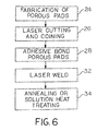
- a porous pad or fiber metal pad 14 is formed or fabricated in known manner using a sintering or diffusion bonding process (block 24).
- the fiber metal pad is then laser cut into a shape which mates with supporting surface 16 of body 12 (block 26).
- the fiber metal pad may be formed as a continuous piece which extends from one supporting surface to another.
- the fiber metal pad may also be coined if desired (block 26).
- fiber metal pad 14 is attached to supporting surface 16 of body 12 using an adhesive (block 28). Alternatively, fiber metal pad 14 may be clamped against supporting surfaces 16, as indicated schematically by arrows 30 in Fig. 1.
- a laser beam is coupled between fiber metal pad 14 and body 12 at a plurality of locations 20 (block 32).
- the mixture of melted and subsequently cooled metal of fiber metal pad 14 and body 12 welds fiber metal pad 14 to body 12.
- the orthopaedic implant is then annealed or solution heat treated (block 34), and the previously applied adhesive removed.
- the laser beam is coupled between fiber metal pad 14 and body 12 at a plurality of locations.
- the plurality of weldment locations 20 may correspond to a predetermined pattern or a random pattern.
- Laser weldment locations 20 preferably have a spacing therebetween of approximately 0.040 and 0.150 inch, and more preferably a spacing of approximately 0.070 inch.
- Figs. 3-5 three different possible patterns of laser weldment locations are shown.
- Fig. 3 illustrates a plurality of weldment locations which define a substantially square pattern.
- Each laser weld location 20 has a diameter D (Fig. 2) of between 0.10 and 0.60 inch, and preferably approximately 0.40 inch.
- Dimensions between adjacent laser weld locations 20, indicated by reference number 36, are approximately 0.80 inch; and the dimension from corner to corner, indicated by reference number 38, is approximately 0.113 inch.
- Fig. 4 illustrates a plurality of weldment locations 20 defining a substantially square pattern with a centrally positioned welding location 20 therein.
- Each weldment location 20 preferably has a diameter D of approximately 0.40 inch.
- Dimensions 40 are approximately 0.031 inch; dimensions 42 are approximately 0.100 inch; dimension 44 is approximately 0.060 inch; and dimension 46 is approximately 0.141 inch.
- Fig. 5 illustrates a plurality of weldment locations 20 which define a substantially hexagonal pattern, including a centrally located weldment location 20.
- orthopaedic implant 10 is in the form of a femoral knee component.
- the method of the present invention may be used with other orthopaedic implants, such as a hip, shoulder, elbow or ankle implant, or a permanently implanted fixation rod.
- porous metal pad 14 is in the form of a fiber metal pad.
- porous metal pads such as a beaded pad or wire mesh may also be utilized with the method of the present invention.
Abstract
Description
- This is a continuation-in-part of U.S. Patent Application Serial No. 08/609,210, filed March 1, 1996, entitled "ORTHOPAEDIC IMPLANT AND METHOD OF MAKING SAME", which is a continuation of U.S. Patent Application Serial No. 08/228,774, filed April 18, 1994, entitled "ORTHOPAEDIC IMPLANT AND METHOD OF MAKING SAME", now U.S. Patent No. 5,504,300.
- The present invention relates to orthopaedic implants, and, more particularly, to orthopaedic implants having a porous metal pad attached thereto.
- Orthopaedic implants, such as knee or hip implants, may include one or more porous surfaces at the exterior thereof. The porous surfaces enhance implant fixation within the bone by allowing bony ingrowth therein or penetration of bone cement. The porous surface is typically in the form of a pad constructed of fiber metal, metal beads or a wire mesh. The fibers, beads or wires are typically interconnected with each other using a sintering or diffusion bonding process. The porous metal pad is cut to shape to fit a supporting surface formed on the orthopaedic implant body.
- One known method of attaching the porous metal pad to the implant body is to clamp the porous metal pad against the supporting surface of the implant body, and thereafter metallurgically bond the porous metal pad to the implant body using a diffusion bonding or sintering process. A problem with sintering the porous metal pad to the implant body is that this process is both time consuming and expensive from a manufacturing standpoint. For example, during sintering, the ramp up and cool down time for a sintering furnace is approximately 14 hours per cycle. If the porous metal pad is being connected, e.g., to the interior bone engaging surface of a femoral knee component, it may take a minimum of three cycles to complete the sintering operation. The complex geometric interior design of the femoral knee component may require that only one or two porous metal pads be attached to the femoral knee component during one cycle of the sintering process. The typical interior ofthe femoral knee component defines five distinct surfaces which require connection with a porous metal pad. Therefore, to completely bond the porous metal pad to the interior of the femoral knee component may require in excess of 42 hours of furnace time. Added to this is the time required to connect the clamping tool to the implant for holding the porous metal pad in contact with the supporting surface of the implant. It is thus apparent that providing a porous metal pad on an implant using a sintering process is relatively time consuming and expensive.
- It is also known to diffusion bond a fiber metal pad to a thin metal foil, which in turn is attached to an orthopaedic implant body using a laser welding process. For details of such an attachment process, reference is hereby made to U.S. Patent Application Serial No.08/609,210, entitled "ORTHOPAEDIC IMPLANT AND METHOD OF MAKING SAME," which is assigned to the assignee ofthe present invention and incorporated herein by reference. In general, a porous metal pad, such as a fiber metal pad, is diffusion bonded to a thin metal foil. The fiber metal pad and thin metal foil are each configured to be received within a recess formed in the orthopaedic implant body. The edges of the thin metal foil extend to the exterior ofthe recess formed in the orthopaedic implant body. A laser welder is used to weld the thin metal foil to the orthopaedic implant body, and thereby indirectly attach the fiber metal pad to the implant body.
- What is needed in the art is a method of attaching a porous metal pad to an orthopaedic implant body wherein the porous metal pad is attached to the implant body at locations other than the periphery of the porous metal pad.
- What is further needed in the art is a method of attaching a porous metal pad to an implant body which is faster than a sintering process.
- The present invention provides a method of attaching a porous metal pad to a body of an orthopaedic implant by coupling a laser beam between the porous metal pad and the body at a plurality of predetermined locations.
- The invention comprises, in one form thereof, a method of making an orthopaedic implant. An orthopaedic implant body is formed which has a supporting surface. A porous metal pad is formed to fit the supporting surface of the body. The porous metal pad is clamped and/or adhesively bonded to the supporting surface. A laser beam is coupled between the porous metal pad and the body at a plurality of locations, so as to form a coalescence of metal between the porous metal pad and the body.
- An advantage of the present invention is that the porous metal pad is attached to the orthopaedic implant body without using the relatively slow process of diffusion bonding or sintering.
- The above-mentioned and other features and advantages of this invention, and the manner of attaining them, will become more apparent and the invention will be better understood by reference to the following description of embodiments of the invention taken in conjunction with the accompanying drawings, wherein:
- Fig. 1 is a perspective view of an embodiment of a femoral knee component manufactured using the method of the present invention;
- Fig. 2 is an enlarged, fragmentary view showing interconnection between a porous metal pad and a body of an orthopaedic implant using the method of the present invention;
- Figs. 3-5 illustrate different embodiments of patterns at which the porous metal pad is laser welded to the implant body; and
- Fig. 6 is a flowchart illustrating an embodiment ofthe method of the present invention.
- Corresponding reference characters indicate corresponding parts throughout the several views. The exemplifications set out herein illustrate one preferred embodiment of the invention, in one form, and such exemplifications are not to be construed as limiting the scope of the invention in any manner.
- Referring now to the drawings, and more particularly to Figs. 1 and 2, there is shown an embodiment of an orthopaedic implant manufactured using the method of the present invention. In the embodiment shown, the orthopaedic implant is in the form of a
femoral knee component 10, including anorthopaedic implant body 12 and aporous metal pad 14. -
Body 12 includes a plurality of adjoining, generally planar supporting surfaces for supporting and attachment withporous metal pad 14, one of which is shown and referenced 16 in Fig. 2.Body 12 is formed from a material such as cobalt-chromium alloy, titanium alloy or stainless steel alloy. -
Porous metal pad 14 is placed against supportingsurface 16 ofbody 12, and attached thereto in a manner as will be described hereinafter.Porous metal pad 14, in the embodiment shown, is in the form of afiber metal pad 14 having a plurality ofmetal fibers 18 which are interconnected together in a known manner, such as by using a sintering or diffusion bonding process.Fiber metal pad 14 is preferably formed from a material such as cobalt-chromium alloy, titanium alloy or stainless steel alloy. -
Fiber metal pad 14 is attached tobody 12 by coupling a laser beam (not shown) betweenfiber metal pad 14 andbody 12, so as to form a coalescence of metal betweenfiber metal pad 14 andbody 12. The process of "coupling" using a laser means that enough energy is transferred into the material to melt the material. An example of a laser which may be utilized with the present invention is a YAG industrial laser manufactured by Lumonics Corporation, Livonia, Michigan, USA, although many other types of commercially available lasers can also be used with the method of the present invention. More particularly, the laser beam is coupled betweenfiber metal pad 14 andbody 12 at a plurality of locations indicated generally byreference numbers 20. As the laser is coupled betweenfiber metal pad 14 andbody 12, a portion offiber metals 18 andbody 12 melt to define a weld bead which interconnectsfiber metal pad 14 andbody 12 upon cooling. The weld bead may be in the form of a substantiallycylindrical layer 22 which extends throughfiber metal pad 14 and intobody 12.Cylindrical layer 22 has a diameter which corresponds to a diameter of the laser beam. In the embodiment shown in the drawings,cylindrical layer 22 has an outside diameter "D" of between approximately 0.020 and 0.050 inch and preferably approximately 0.30 inch. - Although the weld bead produced by the coalescing of material between
fiber metal pad 14 andbody 12 is shown as a substantiallycylindrical layer 22 in Fig. 2, it is also to be understood that the weld bead may be in the form of a cone, solid bead or other shape. The shape of the weld bead is primarily dependent upon the density ofmetal fibers 18 which the laser beam contacts. - The laser utilized with the present invention is adjusted so that the power and beam diameter correspond to the particular type of
porous metal pad 14 which is used. For example, a cobalt-chromium-molybdenumfiber metal pad 14 may be placed in a light box in such a way as to allow light passing through the pores of thefiber metal pad 14 to be detected by a video camera. Digitized images of the pores in the fiber metal pad may be captured with a computer assisted image analysis system. The size distribution of the through pores in the fiber metal pad may be used to estimate a minimum laser beam diameter which is required for the production of quality weldments. The laser beam diameter may be adjusted, e.g., by changing the angle of the reflective mirror in the laser. A laser beam diameter of between approximately 0.015 and 0.030 inch has been found effective to produce a weld diameter of between approximately 0.020 and 0.050 inch. - The phrase "laser beam welding", or other derivative spellings thereof, as used in this application, is intended to mean welding using a high energy source, such as laser beam welding, electron beam welding, plasma welding, etc.
- Referring now to Fig. 6, there is shown a flow chart illustrating an embodiment of the method of the present invention. First, a porous pad or
fiber metal pad 14 is formed or fabricated in known manner using a sintering or diffusion bonding process (block 24). The fiber metal pad is then laser cut into a shape which mates with supportingsurface 16 of body 12 (block 26). The fiber metal pad may be formed as a continuous piece which extends from one supporting surface to another. The fiber metal pad may also be coined if desired (block 26). Thereafter,fiber metal pad 14 is attached to supportingsurface 16 ofbody 12 using an adhesive (block 28). Alternatively,fiber metal pad 14 may be clamped against supportingsurfaces 16, as indicated schematically byarrows 30 in Fig. 1. Afterfiber metal pad 14 is adhesively bonded or clamped tobody 12, a laser beam is coupled betweenfiber metal pad 14 andbody 12 at a plurality of locations 20 (block 32). The mixture of melted and subsequently cooled metal offiber metal pad 14 andbody 12 weldsfiber metal pad 14 tobody 12. The orthopaedic implant is then annealed or solution heat treated (block 34), and the previously applied adhesive removed. - As indicated above, the laser beam is coupled between
fiber metal pad 14 andbody 12 at a plurality of locations. The plurality ofweldment locations 20 may correspond to a predetermined pattern or a random pattern.Laser weldment locations 20 preferably have a spacing therebetween of approximately 0.040 and 0.150 inch, and more preferably a spacing of approximately 0.070 inch. Referring to Figs. 3-5, three different possible patterns of laser weldment locations are shown. Fig. 3 illustrates a plurality of weldment locations which define a substantially square pattern. Eachlaser weld location 20 has a diameter D (Fig. 2) of between 0.10 and 0.60 inch, and preferably approximately 0.40 inch. Dimensions between adjacentlaser weld locations 20, indicated byreference number 36, are approximately 0.80 inch; and the dimension from corner to corner, indicated byreference number 38, is approximately 0.113 inch. - Fig. 4 illustrates a plurality of
weldment locations 20 defining a substantially square pattern with a centrally positionedwelding location 20 therein. Eachweldment location 20 preferably has a diameter D of approximately 0.40 inch.Dimensions 40 are approximately 0.031 inch;dimensions 42 are approximately 0.100 inch;dimension 44 is approximately 0.060 inch; anddimension 46 is approximately 0.141 inch. - Fig. 5 illustrates a plurality of
weldment locations 20 which define a substantially hexagonal pattern, including a centrally locatedweldment location 20. - In the embodiment shown,
orthopaedic implant 10 is in the form of a femoral knee component. However, it is also to be understood that the method of the present invention may be used with other orthopaedic implants, such as a hip, shoulder, elbow or ankle implant, or a permanently implanted fixation rod. - Moreover, in the embodiment shown,
porous metal pad 14 is in the form of a fiber metal pad. However, it is also to be understood that other types of porous metal pads such as a beaded pad or wire mesh may also be utilized with the method of the present invention. - While this invention has been described as having a preferred design, the present invention can be further modified within the spirit and scope of this disclosure. This application is therefore intended to cover any variations, uses, or adaptations of the invention using its general principles. Further, this application is intended to cover such departures from the present disclosure as come within known or customary practice in the art to which this invention pertains and which fall within the limits of the appended claims.
Claims (27)
Applications Claiming Priority (2)
| Application Number | Priority Date | Filing Date | Title |
|---|---|---|---|
| US08/652,193 US5773789A (en) | 1994-04-18 | 1996-05-23 | Method of making an orthopaedic implant having a porous metal pad |
| US652193 | 1996-05-23 |
Publications (2)
| Publication Number | Publication Date |
|---|---|
| EP0808616A2 true EP0808616A2 (en) | 1997-11-26 |
| EP0808616A3 EP0808616A3 (en) | 1998-11-25 |
Family
ID=24615878
Family Applications (1)
| Application Number | Title | Priority Date | Filing Date |
|---|---|---|---|
| EP97201493A Withdrawn EP0808616A3 (en) | 1996-05-23 | 1997-05-16 | Method of making an orthopaedic implant having a porous metal pad |
Country Status (4)
| Country | Link |
|---|---|
| US (1) | US5773789A (en) |
| EP (1) | EP0808616A3 (en) |
| JP (1) | JP3887065B2 (en) |
| CA (1) | CA2204960C (en) |
Families Citing this family (22)
| Publication number | Priority date | Publication date | Assignee | Title |
|---|---|---|---|---|
| US6049054A (en) * | 1994-04-18 | 2000-04-11 | Bristol-Myers Squibb Company | Method of making an orthopaedic implant having a porous metal pad |
| US6132674A (en) | 1995-10-12 | 2000-10-17 | Bristol-Myers Squibb Company | Method of making an orthopaedic implant having a porous surface |
| US6740186B2 (en) * | 2002-02-20 | 2004-05-25 | Zimmer Technology, Inc. | Method of making an orthopeadic implant having a porous metal surface |
| US6945448B2 (en) * | 2002-06-18 | 2005-09-20 | Zimmer Technology, Inc. | Method for attaching a porous metal layer to a metal substrate |
| US7918382B2 (en) | 2002-06-18 | 2011-04-05 | Zimmer Technology, Inc. | Method for attaching a porous metal layer to a metal substrate |
| US6839906B2 (en) * | 2002-08-29 | 2005-01-11 | Jerome Gold | High strength impact resistant knee protector |
| CA2448592C (en) | 2002-11-08 | 2011-01-11 | Howmedica Osteonics Corp. | Laser-produced porous surface |
| US20060147332A1 (en) * | 2004-12-30 | 2006-07-06 | Howmedica Osteonics Corp. | Laser-produced porous structure |
| JP4909992B2 (en) * | 2005-09-08 | 2012-04-04 | インキュメッド・リミテッド・ライアビリティ・カンパニー | Method for bonding a titanium-based mesh to a titanium-based substrate |
| US8728387B2 (en) * | 2005-12-06 | 2014-05-20 | Howmedica Osteonics Corp. | Laser-produced porous surface |
| CA2572095C (en) * | 2005-12-30 | 2009-12-08 | Howmedica Osteonics Corp. | Laser-produced implants |
| US7722735B2 (en) * | 2006-04-06 | 2010-05-25 | C3 Materials Corp. | Microstructure applique and method for making same |
| US8147861B2 (en) | 2006-08-15 | 2012-04-03 | Howmedica Osteonics Corp. | Antimicrobial implant |
| WO2008026316A1 (en) * | 2006-08-31 | 2008-03-06 | Japan Science And Technology Agency | Composite artificial bone |
| US8177849B2 (en) * | 2007-05-07 | 2012-05-15 | Zimmer, Inc. | Methods and apparatuses for attaching tissue to orthopaedic implants |
| WO2009014718A1 (en) | 2007-07-24 | 2009-01-29 | Porex Corporation | Porous laser sintered articles |
| US8727203B2 (en) | 2010-09-16 | 2014-05-20 | Howmedica Osteonics Corp. | Methods for manufacturing porous orthopaedic implants |
| US9364896B2 (en) | 2012-02-07 | 2016-06-14 | Medical Modeling Inc. | Fabrication of hybrid solid-porous medical implantable devices with electron beam melting technology |
| US9180010B2 (en) | 2012-04-06 | 2015-11-10 | Howmedica Osteonics Corp. | Surface modified unit cell lattice structures for optimized secure freeform fabrication |
| US9135374B2 (en) | 2012-04-06 | 2015-09-15 | Howmedica Osteonics Corp. | Surface modified unit cell lattice structures for optimized secure freeform fabrication |
| ITMI20132154A1 (en) * | 2013-12-20 | 2015-06-21 | Adler Ortho S R L | FEMORAL COMPONENT FOR KNEE PROSTHESIS. |
| US11298747B2 (en) | 2017-05-18 | 2022-04-12 | Howmedica Osteonics Corp. | High fatigue strength porous structure |
Citations (10)
| Publication number | Priority date | Publication date | Assignee | Title |
|---|---|---|---|---|
| GB2059267A (en) * | 1979-09-28 | 1981-04-23 | Leuven Res & Dev Vzw | Compound material for prosthetic devices |
| US4835357A (en) * | 1988-06-20 | 1989-05-30 | Williams International Corporation | Sheet metal laser welding |
| EP0330606A1 (en) * | 1988-02-26 | 1989-08-30 | GebràDer Sulzer Aktiengesellschaft | Bone implant |
| US4976738A (en) * | 1985-01-09 | 1990-12-11 | Sulzer Brothers Limited | Porous metal overlay for an implant surface |
| EP0406013A2 (en) * | 1989-06-30 | 1991-01-02 | Ethicon, Inc. | Improved dental inserts for treatment of periodontal disease |
| US5027998A (en) * | 1987-01-16 | 1991-07-02 | Dynamet, Inc. | Clamping mechanism for making porous metal coated implant |
| US5198308A (en) * | 1990-12-21 | 1993-03-30 | Zimmer, Inc. | Titanium porous surface bonded to a cobalt-based alloy substrate in an orthopaedic implant device |
| EP0623687A2 (en) * | 1993-04-06 | 1994-11-09 | Bristol-Myers Squibb Company | Porous coated implant and method of making same |
| GB2281865A (en) * | 1993-09-16 | 1995-03-22 | Cordis Corp | Endoprosthesis having multiple welded junctions |
| EP0678285A2 (en) * | 1994-04-18 | 1995-10-25 | Bristol-Myers Squibb Company | Orthopaedic implant and method of making same |
Family Cites Families (21)
| Publication number | Priority date | Publication date | Assignee | Title |
|---|---|---|---|---|
| US3605123A (en) * | 1969-04-29 | 1971-09-20 | Melpar Inc | Bone implant |
| CA962806A (en) * | 1970-06-04 | 1975-02-18 | Ontario Research Foundation | Surgical prosthetic device |
| GB8318483D0 (en) * | 1983-07-08 | 1983-08-10 | Zimmer Deloro Surgical Ltd | Skeletal implants |
| US4536894A (en) * | 1983-08-04 | 1985-08-27 | Galante Jorge O | Hip prosthesis with flared porous bony ingrowth pads |
| US5030233A (en) * | 1984-10-17 | 1991-07-09 | Paul Ducheyne | Porous flexible metal fiber material for surgical implantation |
| CA1264674A (en) * | 1984-10-17 | 1990-01-23 | Paul Ducheyne | Porous flexible metal fiber material for surgical implantation |
| CH665554A5 (en) * | 1985-02-07 | 1988-05-31 | Sulzer Ag | BONE IMPLANT. |
| US4660755A (en) * | 1985-09-09 | 1987-04-28 | Zimmer, Inc. | Method for constructing a surgical implant |
| US4636219A (en) * | 1985-12-05 | 1987-01-13 | Techmedica, Inc. | Prosthesis device fabrication |
| CH668903A5 (en) * | 1986-02-18 | 1989-02-15 | Sulzer Ag | SHAFT FOR A HIP JOINT PROSTHESIS. |
| IT1214566B (en) * | 1986-12-02 | 1990-01-18 | Cremascoli Spa G | FEMORAL STEM HIP PROSTHESIS, FOR HUMAN HIP PROSTHETIC REPLACEMENT. |
| US5013324A (en) * | 1987-08-24 | 1991-05-07 | Zimmer, Inc. | Prosthetic implant with wrapped porous surface |
| US5139528A (en) * | 1988-02-26 | 1992-08-18 | Sulzer Brothers Limited | Method of securing a mesh to a metal substrate for a bone implant |
| US5080674A (en) * | 1988-09-08 | 1992-01-14 | Zimmer, Inc. | Attachment mechanism for securing an additional portion to an implant |
| US5057108A (en) * | 1990-01-12 | 1991-10-15 | Zimmer, Inc. | Method of surface finishing orthopedic implant devices |
| US5108432A (en) * | 1990-06-24 | 1992-04-28 | Pfizer Hospital Products Group, Inc. | Porous fixation surface |
| US5242706A (en) * | 1991-07-31 | 1993-09-07 | The United States Of America As Represented By The Secretary Of The Navy | Laser-deposited biocompatible films and methods and apparatuses for producing same |
| EP0526682B1 (en) * | 1991-08-07 | 1997-03-05 | Oscobal Ag | Endoprosthesis with a metal wire mesh |
| US5236457A (en) * | 1992-02-27 | 1993-08-17 | Zimmer, Inc. | Method of making an implant having a metallic porous surface |
| US5245155A (en) * | 1992-03-06 | 1993-09-14 | General Electric Company | Single point powder feed nozzle for use in laser welding |
| US5387243A (en) * | 1992-11-23 | 1995-02-07 | Zimmer, Inc. | Method for converting a cementable implant to a press fit implant |
-
1996
- 1996-05-23 US US08/652,193 patent/US5773789A/en not_active Expired - Lifetime
-
1997
- 1997-05-09 CA CA002204960A patent/CA2204960C/en not_active Expired - Lifetime
- 1997-05-16 EP EP97201493A patent/EP0808616A3/en not_active Withdrawn
- 1997-05-23 JP JP13366497A patent/JP3887065B2/en not_active Expired - Lifetime
Patent Citations (10)
| Publication number | Priority date | Publication date | Assignee | Title |
|---|---|---|---|---|
| GB2059267A (en) * | 1979-09-28 | 1981-04-23 | Leuven Res & Dev Vzw | Compound material for prosthetic devices |
| US4976738A (en) * | 1985-01-09 | 1990-12-11 | Sulzer Brothers Limited | Porous metal overlay for an implant surface |
| US5027998A (en) * | 1987-01-16 | 1991-07-02 | Dynamet, Inc. | Clamping mechanism for making porous metal coated implant |
| EP0330606A1 (en) * | 1988-02-26 | 1989-08-30 | GebràDer Sulzer Aktiengesellschaft | Bone implant |
| US4835357A (en) * | 1988-06-20 | 1989-05-30 | Williams International Corporation | Sheet metal laser welding |
| EP0406013A2 (en) * | 1989-06-30 | 1991-01-02 | Ethicon, Inc. | Improved dental inserts for treatment of periodontal disease |
| US5198308A (en) * | 1990-12-21 | 1993-03-30 | Zimmer, Inc. | Titanium porous surface bonded to a cobalt-based alloy substrate in an orthopaedic implant device |
| EP0623687A2 (en) * | 1993-04-06 | 1994-11-09 | Bristol-Myers Squibb Company | Porous coated implant and method of making same |
| GB2281865A (en) * | 1993-09-16 | 1995-03-22 | Cordis Corp | Endoprosthesis having multiple welded junctions |
| EP0678285A2 (en) * | 1994-04-18 | 1995-10-25 | Bristol-Myers Squibb Company | Orthopaedic implant and method of making same |
Also Published As
| Publication number | Publication date |
|---|---|
| CA2204960C (en) | 2005-08-23 |
| JPH1043216A (en) | 1998-02-17 |
| CA2204960A1 (en) | 1997-11-23 |
| US5773789A (en) | 1998-06-30 |
| EP0808616A3 (en) | 1998-11-25 |
| JP3887065B2 (en) | 2007-02-28 |
Similar Documents
| Publication | Publication Date | Title |
|---|---|---|
| US6049054A (en) | Method of making an orthopaedic implant having a porous metal pad | |
| US5973222A (en) | Orthopedic implant having a porous metal pad | |
| US5773789A (en) | Method of making an orthopaedic implant having a porous metal pad | |
| US5443510A (en) | Porous coated implant and method of making same | |
| EP0678285B1 (en) | Method of making an orthopaedic implant | |
| EP0225838B1 (en) | Bone prosthesis device | |
| US4969904A (en) | Bone implant | |
| US4829152A (en) | Method of resistance welding a porous body to a substrate | |
| EP0934139B1 (en) | Improved welding method | |
| JP5800774B2 (en) | Method for fixing strand ends and resulting apparatus | |
| US3905777A (en) | Composite and porous metallic members which can be used for bone prosthesis | |
| EP3169278B1 (en) | Resistance welding a porous metal layer to a metal substrate utilizing an intermediate element | |
| EP1708645A2 (en) | Medical devices and methods of making the same | |
| NZ280547A (en) | Expandable metal stent comprising a plurality of cut, interconnected cylindrical elements | |
| EP1524096A3 (en) | Resin mold and method for manufacturing the same | |
| WO2012068492A1 (en) | Resistance welding a porous metal layer to a metal substrate | |
| JP3115456B2 (en) | Laser welding method for galvanized steel sheet | |
| US5139528A (en) | Method of securing a mesh to a metal substrate for a bone implant | |
| EP0960682A2 (en) | Process of cladding by welding | |
| US20060237407A1 (en) | Medical devices having laser brazed joints | |
| JP2008290129A (en) | Method of welding metallic member | |
| EP1288992A3 (en) | Electrode, manufacturing method thereof, and metal vapor discharge lamp | |
| US20090316418A1 (en) | Component With a Weld Projection Having a Projection and Lamp Housing Part Comprising a Component with a Weld Projection | |
| EP0598450A1 (en) | Prosthetic implant and method of making same | |
| EP0478769A4 (en) | Porous metal surface and method of production |
Legal Events
| Date | Code | Title | Description |
|---|---|---|---|
| PUAI | Public reference made under article 153(3) epc to a published international application that has entered the european phase |
Free format text: ORIGINAL CODE: 0009012 |
|
| AK | Designated contracting states |
Kind code of ref document: A2 Designated state(s): DE ES FR GB IT |
|
| PUAL | Search report despatched |
Free format text: ORIGINAL CODE: 0009013 |
|
| AK | Designated contracting states |
Kind code of ref document: A3 Designated state(s): DE ES FR GB IT |
|
| 17P | Request for examination filed |
Effective date: 19990525 |
|
| 17Q | First examination report despatched |
Effective date: 20011122 |
|
| STAA | Information on the status of an ep patent application or granted ep patent |
Free format text: STATUS: THE APPLICATION IS DEEMED TO BE WITHDRAWN |
|
| 18D | Application deemed to be withdrawn |
Effective date: 20030213 |