EP0808619A2 - Elbow joint endroprosthesis - Google Patents
Elbow joint endroprosthesis Download PDFInfo
- Publication number
- EP0808619A2 EP0808619A2 EP97107605A EP97107605A EP0808619A2 EP 0808619 A2 EP0808619 A2 EP 0808619A2 EP 97107605 A EP97107605 A EP 97107605A EP 97107605 A EP97107605 A EP 97107605A EP 0808619 A2 EP0808619 A2 EP 0808619A2
- Authority
- EP
- European Patent Office
- Prior art keywords
- elbow joint
- joint endoprosthesis
- endoprosthesis according
- radius
- sliding body
- Prior art date
- Legal status (The legal status is an assumption and is not a legal conclusion. Google has not performed a legal analysis and makes no representation as to the accuracy of the status listed.)
- Granted
Links
Images


Classifications
-
- A—HUMAN NECESSITIES
- A61—MEDICAL OR VETERINARY SCIENCE; HYGIENE
- A61L—METHODS OR APPARATUS FOR STERILISING MATERIALS OR OBJECTS IN GENERAL; DISINFECTION, STERILISATION OR DEODORISATION OF AIR; CHEMICAL ASPECTS OF BANDAGES, DRESSINGS, ABSORBENT PADS OR SURGICAL ARTICLES; MATERIALS FOR BANDAGES, DRESSINGS, ABSORBENT PADS OR SURGICAL ARTICLES
- A61L27/00—Materials for grafts or prostheses or for coating grafts or prostheses
- A61L27/02—Inorganic materials
- A61L27/04—Metals or alloys
- A61L27/045—Cobalt or cobalt alloys
-
- A—HUMAN NECESSITIES
- A61—MEDICAL OR VETERINARY SCIENCE; HYGIENE
- A61F—FILTERS IMPLANTABLE INTO BLOOD VESSELS; PROSTHESES; DEVICES PROVIDING PATENCY TO, OR PREVENTING COLLAPSING OF, TUBULAR STRUCTURES OF THE BODY, e.g. STENTS; ORTHOPAEDIC, NURSING OR CONTRACEPTIVE DEVICES; FOMENTATION; TREATMENT OR PROTECTION OF EYES OR EARS; BANDAGES, DRESSINGS OR ABSORBENT PADS; FIRST-AID KITS
- A61F2/00—Filters implantable into blood vessels; Prostheses, i.e. artificial substitutes or replacements for parts of the body; Appliances for connecting them with the body; Devices providing patency to, or preventing collapsing of, tubular structures of the body, e.g. stents
- A61F2/02—Prostheses implantable into the body
- A61F2/30—Joints
- A61F2/38—Joints for elbows or knees
- A61F2/3804—Joints for elbows or knees for elbows
-
- A—HUMAN NECESSITIES
- A61—MEDICAL OR VETERINARY SCIENCE; HYGIENE
- A61L—METHODS OR APPARATUS FOR STERILISING MATERIALS OR OBJECTS IN GENERAL; DISINFECTION, STERILISATION OR DEODORISATION OF AIR; CHEMICAL ASPECTS OF BANDAGES, DRESSINGS, ABSORBENT PADS OR SURGICAL ARTICLES; MATERIALS FOR BANDAGES, DRESSINGS, ABSORBENT PADS OR SURGICAL ARTICLES
- A61L27/00—Materials for grafts or prostheses or for coating grafts or prostheses
- A61L27/14—Macromolecular materials
- A61L27/16—Macromolecular materials obtained by reactions only involving carbon-to-carbon unsaturated bonds
-
- A—HUMAN NECESSITIES
- A61—MEDICAL OR VETERINARY SCIENCE; HYGIENE
- A61F—FILTERS IMPLANTABLE INTO BLOOD VESSELS; PROSTHESES; DEVICES PROVIDING PATENCY TO, OR PREVENTING COLLAPSING OF, TUBULAR STRUCTURES OF THE BODY, e.g. STENTS; ORTHOPAEDIC, NURSING OR CONTRACEPTIVE DEVICES; FOMENTATION; TREATMENT OR PROTECTION OF EYES OR EARS; BANDAGES, DRESSINGS OR ABSORBENT PADS; FIRST-AID KITS
- A61F2/00—Filters implantable into blood vessels; Prostheses, i.e. artificial substitutes or replacements for parts of the body; Appliances for connecting them with the body; Devices providing patency to, or preventing collapsing of, tubular structures of the body, e.g. stents
- A61F2/02—Prostheses implantable into the body
- A61F2/30—Joints
- A61F2002/30001—Additional features of subject-matter classified in A61F2/28, A61F2/30 and subgroups thereof
- A61F2002/30108—Shapes
- A61F2002/3011—Cross-sections or two-dimensional shapes
- A61F2002/30112—Rounded shapes, e.g. with rounded corners
-
- A—HUMAN NECESSITIES
- A61—MEDICAL OR VETERINARY SCIENCE; HYGIENE
- A61F—FILTERS IMPLANTABLE INTO BLOOD VESSELS; PROSTHESES; DEVICES PROVIDING PATENCY TO, OR PREVENTING COLLAPSING OF, TUBULAR STRUCTURES OF THE BODY, e.g. STENTS; ORTHOPAEDIC, NURSING OR CONTRACEPTIVE DEVICES; FOMENTATION; TREATMENT OR PROTECTION OF EYES OR EARS; BANDAGES, DRESSINGS OR ABSORBENT PADS; FIRST-AID KITS
- A61F2/00—Filters implantable into blood vessels; Prostheses, i.e. artificial substitutes or replacements for parts of the body; Appliances for connecting them with the body; Devices providing patency to, or preventing collapsing of, tubular structures of the body, e.g. stents
- A61F2/02—Prostheses implantable into the body
- A61F2/30—Joints
- A61F2002/30001—Additional features of subject-matter classified in A61F2/28, A61F2/30 and subgroups thereof
- A61F2002/30316—The prosthesis having different structural features at different locations within the same prosthesis; Connections between prosthetic parts; Special structural features of bone or joint prostheses not otherwise provided for
- A61F2002/30329—Connections or couplings between prosthetic parts, e.g. between modular parts; Connecting elements
- A61F2002/30331—Connections or couplings between prosthetic parts, e.g. between modular parts; Connecting elements made by longitudinally pushing a protrusion into a complementarily-shaped recess, e.g. held by friction fit
- A61F2002/30354—Cylindrically-shaped protrusion and recess, e.g. cylinder of circular basis
- A61F2002/30355—Cylinder of elliptical or oval basis
-
- A—HUMAN NECESSITIES
- A61—MEDICAL OR VETERINARY SCIENCE; HYGIENE
- A61F—FILTERS IMPLANTABLE INTO BLOOD VESSELS; PROSTHESES; DEVICES PROVIDING PATENCY TO, OR PREVENTING COLLAPSING OF, TUBULAR STRUCTURES OF THE BODY, e.g. STENTS; ORTHOPAEDIC, NURSING OR CONTRACEPTIVE DEVICES; FOMENTATION; TREATMENT OR PROTECTION OF EYES OR EARS; BANDAGES, DRESSINGS OR ABSORBENT PADS; FIRST-AID KITS
- A61F2/00—Filters implantable into blood vessels; Prostheses, i.e. artificial substitutes or replacements for parts of the body; Appliances for connecting them with the body; Devices providing patency to, or preventing collapsing of, tubular structures of the body, e.g. stents
- A61F2/02—Prostheses implantable into the body
- A61F2/30—Joints
- A61F2002/30001—Additional features of subject-matter classified in A61F2/28, A61F2/30 and subgroups thereof
- A61F2002/30316—The prosthesis having different structural features at different locations within the same prosthesis; Connections between prosthetic parts; Special structural features of bone or joint prostheses not otherwise provided for
- A61F2002/30329—Connections or couplings between prosthetic parts, e.g. between modular parts; Connecting elements
- A61F2002/30331—Connections or couplings between prosthetic parts, e.g. between modular parts; Connecting elements made by longitudinally pushing a protrusion into a complementarily-shaped recess, e.g. held by friction fit
- A61F2002/30362—Connections or couplings between prosthetic parts, e.g. between modular parts; Connecting elements made by longitudinally pushing a protrusion into a complementarily-shaped recess, e.g. held by friction fit with possibility of relative movement between the protrusion and the recess
- A61F2002/30369—Limited lateral translation of the protrusion within a larger recess
-
- A—HUMAN NECESSITIES
- A61—MEDICAL OR VETERINARY SCIENCE; HYGIENE
- A61F—FILTERS IMPLANTABLE INTO BLOOD VESSELS; PROSTHESES; DEVICES PROVIDING PATENCY TO, OR PREVENTING COLLAPSING OF, TUBULAR STRUCTURES OF THE BODY, e.g. STENTS; ORTHOPAEDIC, NURSING OR CONTRACEPTIVE DEVICES; FOMENTATION; TREATMENT OR PROTECTION OF EYES OR EARS; BANDAGES, DRESSINGS OR ABSORBENT PADS; FIRST-AID KITS
- A61F2/00—Filters implantable into blood vessels; Prostheses, i.e. artificial substitutes or replacements for parts of the body; Appliances for connecting them with the body; Devices providing patency to, or preventing collapsing of, tubular structures of the body, e.g. stents
- A61F2/02—Prostheses implantable into the body
- A61F2/30—Joints
- A61F2002/30001—Additional features of subject-matter classified in A61F2/28, A61F2/30 and subgroups thereof
- A61F2002/30316—The prosthesis having different structural features at different locations within the same prosthesis; Connections between prosthetic parts; Special structural features of bone or joint prostheses not otherwise provided for
- A61F2002/30329—Connections or couplings between prosthetic parts, e.g. between modular parts; Connecting elements
- A61F2002/30383—Connections or couplings between prosthetic parts, e.g. between modular parts; Connecting elements made by laterally inserting a protrusion, e.g. a rib into a complementarily-shaped groove
- A61F2002/3039—Connections or couplings between prosthetic parts, e.g. between modular parts; Connecting elements made by laterally inserting a protrusion, e.g. a rib into a complementarily-shaped groove with possibility of relative movement of the rib within the groove
- A61F2002/30398—Sliding
- A61F2002/304—Sliding with additional means for limiting said sliding
-
- A—HUMAN NECESSITIES
- A61—MEDICAL OR VETERINARY SCIENCE; HYGIENE
- A61F—FILTERS IMPLANTABLE INTO BLOOD VESSELS; PROSTHESES; DEVICES PROVIDING PATENCY TO, OR PREVENTING COLLAPSING OF, TUBULAR STRUCTURES OF THE BODY, e.g. STENTS; ORTHOPAEDIC, NURSING OR CONTRACEPTIVE DEVICES; FOMENTATION; TREATMENT OR PROTECTION OF EYES OR EARS; BANDAGES, DRESSINGS OR ABSORBENT PADS; FIRST-AID KITS
- A61F2/00—Filters implantable into blood vessels; Prostheses, i.e. artificial substitutes or replacements for parts of the body; Appliances for connecting them with the body; Devices providing patency to, or preventing collapsing of, tubular structures of the body, e.g. stents
- A61F2/02—Prostheses implantable into the body
- A61F2/30—Joints
- A61F2002/30001—Additional features of subject-matter classified in A61F2/28, A61F2/30 and subgroups thereof
- A61F2002/30316—The prosthesis having different structural features at different locations within the same prosthesis; Connections between prosthetic parts; Special structural features of bone or joint prostheses not otherwise provided for
- A61F2002/30329—Connections or couplings between prosthetic parts, e.g. between modular parts; Connecting elements
- A61F2002/30476—Connections or couplings between prosthetic parts, e.g. between modular parts; Connecting elements locked by an additional locking mechanism
- A61F2002/305—Snap connection
-
- A—HUMAN NECESSITIES
- A61—MEDICAL OR VETERINARY SCIENCE; HYGIENE
- A61F—FILTERS IMPLANTABLE INTO BLOOD VESSELS; PROSTHESES; DEVICES PROVIDING PATENCY TO, OR PREVENTING COLLAPSING OF, TUBULAR STRUCTURES OF THE BODY, e.g. STENTS; ORTHOPAEDIC, NURSING OR CONTRACEPTIVE DEVICES; FOMENTATION; TREATMENT OR PROTECTION OF EYES OR EARS; BANDAGES, DRESSINGS OR ABSORBENT PADS; FIRST-AID KITS
- A61F2/00—Filters implantable into blood vessels; Prostheses, i.e. artificial substitutes or replacements for parts of the body; Appliances for connecting them with the body; Devices providing patency to, or preventing collapsing of, tubular structures of the body, e.g. stents
- A61F2/02—Prostheses implantable into the body
- A61F2/30—Joints
- A61F2002/30001—Additional features of subject-matter classified in A61F2/28, A61F2/30 and subgroups thereof
- A61F2002/30316—The prosthesis having different structural features at different locations within the same prosthesis; Connections between prosthetic parts; Special structural features of bone or joint prostheses not otherwise provided for
- A61F2002/30535—Special structural features of bone or joint prostheses not otherwise provided for
- A61F2002/30574—Special structural features of bone or joint prostheses not otherwise provided for with an integral complete or partial collar or flange
-
- A—HUMAN NECESSITIES
- A61—MEDICAL OR VETERINARY SCIENCE; HYGIENE
- A61F—FILTERS IMPLANTABLE INTO BLOOD VESSELS; PROSTHESES; DEVICES PROVIDING PATENCY TO, OR PREVENTING COLLAPSING OF, TUBULAR STRUCTURES OF THE BODY, e.g. STENTS; ORTHOPAEDIC, NURSING OR CONTRACEPTIVE DEVICES; FOMENTATION; TREATMENT OR PROTECTION OF EYES OR EARS; BANDAGES, DRESSINGS OR ABSORBENT PADS; FIRST-AID KITS
- A61F2/00—Filters implantable into blood vessels; Prostheses, i.e. artificial substitutes or replacements for parts of the body; Appliances for connecting them with the body; Devices providing patency to, or preventing collapsing of, tubular structures of the body, e.g. stents
- A61F2/02—Prostheses implantable into the body
- A61F2/30—Joints
- A61F2002/30001—Additional features of subject-matter classified in A61F2/28, A61F2/30 and subgroups thereof
- A61F2002/30621—Features concerning the anatomical functioning or articulation of the prosthetic joint
- A61F2002/30624—Hinged joint, e.g. with transverse axle restricting the movement
-
- A—HUMAN NECESSITIES
- A61—MEDICAL OR VETERINARY SCIENCE; HYGIENE
- A61F—FILTERS IMPLANTABLE INTO BLOOD VESSELS; PROSTHESES; DEVICES PROVIDING PATENCY TO, OR PREVENTING COLLAPSING OF, TUBULAR STRUCTURES OF THE BODY, e.g. STENTS; ORTHOPAEDIC, NURSING OR CONTRACEPTIVE DEVICES; FOMENTATION; TREATMENT OR PROTECTION OF EYES OR EARS; BANDAGES, DRESSINGS OR ABSORBENT PADS; FIRST-AID KITS
- A61F2/00—Filters implantable into blood vessels; Prostheses, i.e. artificial substitutes or replacements for parts of the body; Appliances for connecting them with the body; Devices providing patency to, or preventing collapsing of, tubular structures of the body, e.g. stents
- A61F2/02—Prostheses implantable into the body
- A61F2/30—Joints
- A61F2002/30001—Additional features of subject-matter classified in A61F2/28, A61F2/30 and subgroups thereof
- A61F2002/30621—Features concerning the anatomical functioning or articulation of the prosthetic joint
- A61F2002/30649—Ball-and-socket joints
- A61F2002/30662—Ball-and-socket joints with rotation-limiting means
-
- A—HUMAN NECESSITIES
- A61—MEDICAL OR VETERINARY SCIENCE; HYGIENE
- A61F—FILTERS IMPLANTABLE INTO BLOOD VESSELS; PROSTHESES; DEVICES PROVIDING PATENCY TO, OR PREVENTING COLLAPSING OF, TUBULAR STRUCTURES OF THE BODY, e.g. STENTS; ORTHOPAEDIC, NURSING OR CONTRACEPTIVE DEVICES; FOMENTATION; TREATMENT OR PROTECTION OF EYES OR EARS; BANDAGES, DRESSINGS OR ABSORBENT PADS; FIRST-AID KITS
- A61F2/00—Filters implantable into blood vessels; Prostheses, i.e. artificial substitutes or replacements for parts of the body; Appliances for connecting them with the body; Devices providing patency to, or preventing collapsing of, tubular structures of the body, e.g. stents
- A61F2/02—Prostheses implantable into the body
- A61F2/30—Joints
- A61F2/38—Joints for elbows or knees
- A61F2/3804—Joints for elbows or knees for elbows
- A61F2002/3827—Radial components
-
- A—HUMAN NECESSITIES
- A61—MEDICAL OR VETERINARY SCIENCE; HYGIENE
- A61F—FILTERS IMPLANTABLE INTO BLOOD VESSELS; PROSTHESES; DEVICES PROVIDING PATENCY TO, OR PREVENTING COLLAPSING OF, TUBULAR STRUCTURES OF THE BODY, e.g. STENTS; ORTHOPAEDIC, NURSING OR CONTRACEPTIVE DEVICES; FOMENTATION; TREATMENT OR PROTECTION OF EYES OR EARS; BANDAGES, DRESSINGS OR ABSORBENT PADS; FIRST-AID KITS
- A61F2/00—Filters implantable into blood vessels; Prostheses, i.e. artificial substitutes or replacements for parts of the body; Appliances for connecting them with the body; Devices providing patency to, or preventing collapsing of, tubular structures of the body, e.g. stents
- A61F2/02—Prostheses implantable into the body
- A61F2/30—Joints
- A61F2/38—Joints for elbows or knees
- A61F2/3804—Joints for elbows or knees for elbows
- A61F2002/3831—Ulnar components
-
- A—HUMAN NECESSITIES
- A61—MEDICAL OR VETERINARY SCIENCE; HYGIENE
- A61F—FILTERS IMPLANTABLE INTO BLOOD VESSELS; PROSTHESES; DEVICES PROVIDING PATENCY TO, OR PREVENTING COLLAPSING OF, TUBULAR STRUCTURES OF THE BODY, e.g. STENTS; ORTHOPAEDIC, NURSING OR CONTRACEPTIVE DEVICES; FOMENTATION; TREATMENT OR PROTECTION OF EYES OR EARS; BANDAGES, DRESSINGS OR ABSORBENT PADS; FIRST-AID KITS
- A61F2220/00—Fixations or connections for prostheses classified in groups A61F2/00 - A61F2/26 or A61F2/82 or A61F9/00 or A61F11/00 or subgroups thereof
- A61F2220/0025—Connections or couplings between prosthetic parts, e.g. between modular parts; Connecting elements
- A61F2220/0033—Connections or couplings between prosthetic parts, e.g. between modular parts; Connecting elements made by longitudinally pushing a protrusion into a complementary-shaped recess, e.g. held by friction fit
-
- A—HUMAN NECESSITIES
- A61—MEDICAL OR VETERINARY SCIENCE; HYGIENE
- A61F—FILTERS IMPLANTABLE INTO BLOOD VESSELS; PROSTHESES; DEVICES PROVIDING PATENCY TO, OR PREVENTING COLLAPSING OF, TUBULAR STRUCTURES OF THE BODY, e.g. STENTS; ORTHOPAEDIC, NURSING OR CONTRACEPTIVE DEVICES; FOMENTATION; TREATMENT OR PROTECTION OF EYES OR EARS; BANDAGES, DRESSINGS OR ABSORBENT PADS; FIRST-AID KITS
- A61F2230/00—Geometry of prostheses classified in groups A61F2/00 - A61F2/26 or A61F2/82 or A61F9/00 or A61F11/00 or subgroups thereof
- A61F2230/0002—Two-dimensional shapes, e.g. cross-sections
- A61F2230/0004—Rounded shapes, e.g. with rounded corners
-
- A—HUMAN NECESSITIES
- A61—MEDICAL OR VETERINARY SCIENCE; HYGIENE
- A61F—FILTERS IMPLANTABLE INTO BLOOD VESSELS; PROSTHESES; DEVICES PROVIDING PATENCY TO, OR PREVENTING COLLAPSING OF, TUBULAR STRUCTURES OF THE BODY, e.g. STENTS; ORTHOPAEDIC, NURSING OR CONTRACEPTIVE DEVICES; FOMENTATION; TREATMENT OR PROTECTION OF EYES OR EARS; BANDAGES, DRESSINGS OR ABSORBENT PADS; FIRST-AID KITS
- A61F2310/00—Prostheses classified in A61F2/28 or A61F2/30 - A61F2/44 being constructed from or coated with a particular material
- A61F2310/00005—The prosthesis being constructed from a particular material
- A61F2310/00011—Metals or alloys
- A61F2310/00029—Cobalt-based alloys, e.g. Co-Cr alloys or Vitallium
Definitions
- the invention relates to an elbow joint endoprosthesis with a humerus part, an ulna part and a radius part, in which the ulna part is guided in a pivot bearing in the region of the humerus part and the radius part is pivotably and displaceably held in a pan in the region of the ulna part.
- the invention is based on the object in the case of an elbow joint endoprosthesis of the type mentioned at the beginning Art to improve the articulation between the radius part and the ulna part.
- the radius part is pivotally mounted in a sliding body displaceable in the pan.
- the provision of two separate articulation surfaces according to the invention results, namely a partially spherical sliding surface for pivoting movements between the radius head and the sliding body on the one hand and a substantially flat sliding surface for transverse movements between the sliding body and the pan, on the other hand, better introduction of the pivoting movements between the radius head and the ulna part, without having to do without the transverse mobility of the radius head within the pan.
- the sliding body can be better held in the pan by the muscle and ligament apparatus than a radius head which can move freely in the pan, so that the probability of dislocation in the region of the bearing of the radius head decreases under extreme loads.
- the enlargement of the articulation surfaces as a result of the arrangement according to the invention also reduces the surface pressures between the surfaces sliding on one another and thus the wear on the prosthesis component made of the softer plastic material.
- a preferred embodiment of the invention provides that the sliding body is movable perpendicular to a central axis of the pan with two degrees of freedom, so that it can move in the pan both in the direction of an ulna shaft of the ulna part and transversely to this direction.
- This is preferably achieved by the fact that the flat body lying with its flat top against a correspondingly flat bottom of the pan has lateral dimensions which are smaller than the corresponding inner dimensions of the pan, so that between a circumferential inner wall of the pan delimiting the bottom and a lateral circumferential surface of the sliding body a play of at least 1 mm or preferably a little more is present on all sides if the slider, in its rest position, engages in the middle of the pan with the forearm not twisted.
- the sliding body and the inner wall of the pan are preferably rotationally symmetrical with respect to their respective central axes, these being expediently aligned with one another when the sliding body is arranged centrally in the pan.
- the inner wall can expediently also be in the form of an ellipse.
- Crucial in the design of the inner wall is the possibility that the sliding body with its limits is guided on the inner wall of the pan so that the sliding body cannot get stuck in the pan.
- the inner wall of the pan is formed with continuously merging sections, each of which is provided for a flat contact of the sliding body.
- the assignment of the sliding body to the socket is expediently dependent on the respective anatomical conditions of a patient to be treated with the prosthesis and a respective tilting position of the radius part.
- the position of the sliding body with respect to the pan also depends on these factors when it is in its rest position with the forearm not twisted. Even in this rest position, the sliding body can be located outside the center of the pan.
- the sliding body has a partially spherical recess which is adapted to a spherical shape of the radius head and into which the radius head engages essentially without play, so that the outer surface of the radius head and the inner surface of the recess rest against one another and slide on one another, whereby they form the articulation surface for the pivoting movement of the radius head in relation to the ulna part.
- the partially spherical inner surface of the recess is slightly larger than the surface of a hemisphere.
- the sliding body expediently consists of a Body-friendly plastic material, preferably made of high density polyethylene (HDPE).
- HDPE high density polyethylene
- This material has sufficient elasticity that makes it possible to snap the radius head into the recess by elastically expanding the wall of the recess around an outlet opening for a slim neck of the radius part adjoining the radius head by axial pressure on the radius part until the Radius head enters the recess.
- the deformed wall area then returns to its starting position.
- the pan is preferably formed on the underside of a boom which is substantially perpendicular to an ulna shaft of the ulna part and to the pivoting plane of the pivot bearing and which is expediently connected in one piece to the ulna part, so that the boom and thus the pan together with the ulna part opposite the Humeral part are pivotable.
- the ulna part and the extension arm preferably consist of a body-compatible metallic implant material, preferably of CoCrMo, so that it is in connection with the sliding body made of HDPE in the area of the flat articulation surface between the sliding body and the bottom of the Cup, as well as in the area of the partially spherical articulation surface between the radius head and the sliding body, there is a wear-reducing material pairing CoCrMo / HDPE.
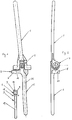
- the elbow joint endoprosthesis shown in the drawing consists essentially of a humerus part 1, an ulna part 2 pivotably mounted in a pivot bearing 4 of the humerus part 1 and a radius part 3, the spherical radius head 7 of which is inserted into a partially spherical recess 9 of a sliding body 5, which in turn is inserted is mounted in a pan 6 on the underside of a boom 8 projecting laterally beyond the ulna part 2.
- the sliding body 5 made of high-density polyethylene (HDPE) has a substantially flat upper side 10, which lies flat against a downwardly facing flat bottom 11 of the pan 6, a cylindrical surface perpendicular to the upper side 10 Circumferential surface 12, as well as an underside 13 facing the radius part 3, towards which the recess 9 serving to receive the radius head 7 opens.
- a peripheral edge 14 between the peripheral surface 12 and the upper side 8 is rounded, its radius of curvature corresponding to the radius of curvature of a rounded transition 15 between the bottom 11 of the pan 6 and an inner wall 16 of the pan 6 delimiting the bottom 11 in the lateral direction.
- the diameter of the recess 9 corresponds to that of the radius head 7, so that the partially spherical inner surface of the recess 9 bears against the spherical surface of the radius head 7 and slides thereon.
- the radius head 7 is in one piece with an adjacent slimmer cylindrical neck 17, a disc-shaped collar 18 arranged below the neck 17 with a circular cross section and a radius shaft 19 adjacent to the collar 18 with a diameter corresponding to the diameter of the neck 17 formed from CoCrMo, so that the articulation surface for the pivoting movement, ie the partially spherical inner surface of the recess 9 and the spherical surface of the radius head 7, which abut and slide against one another, is formed by the low-wear material pairing HDPE / CoCrMo.
- the inner part-spherical surface of the recess 9 is slightly larger than a hemisphere, i.e. their center angle ⁇ in a sectional plane through the central axis 20 of the radius part 3 is greater than 180 degrees, so that the radius head 7 inserted into the recess 9 in said sectional plane is enclosed on a larger part of its circumference by the sliding body 5 and is held in the recess 9 .
- a wall 21 of the sliding body 5 surrounding the recess 9 is elastically expanded in the region of an outlet opening 22 for the neck 17 of the radius part 3 so that the radius head 7 can be snapped into the recess 9, i.e. with its largest diameter passes through the outlet opening 22.
- the outlet opening 22 is tapered inwards conically, so that the wall 21 widens in this area as a result of wedge forces when the radius head 7 of the radius part 3 has its upper side in from the outside in the outlet opening 22 is inserted and the radial part 3 is then subjected to an axial compressive force.
- the deformed wall 21 of the sliding body 5 returns to its starting position as a result of the elastic restoring force and holds the radius head 7 firmly in the recess 9.
- the cylindrical inner wall 16 of the socket 6, which is rotationally symmetrical with respect to its central axis 23, has a diameter which is somewhat larger than the outer diameter of the cylindrical peripheral surface 12 of the sliding body 5, so that with a central arrangement of the radius head 7 in the socket 6 and with aligned central axes 20 , 23, corresponding to a rest position of the radius part 3 with the forearm not twisted, there is greater play on all sides between the inner wall 16 of the socket 6 and the peripheral surface 12 of the sliding body 5.
- the outer diameter of the circumferential surface 12 is 10 mm, so that the play, ie the width of a circumferential gap between the sliding body 5 and the pan 6 is 1.5 mm everywhere in the rest position.
- the sliding body 5 can move parallel to the bottom 11 of the pan 6 with two degrees of freedom when the forearm is rotated about its longitudinal axis.
- the sliding body 5 in the socket 6 adjusts itself to the anatomical conditions found and the tilting position of the radius part.
- the sliding body With appropriate implantation of the elbow joint, the sliding body can be in the rest position with the forearm not twisted in the middle of the socket 6.
- the pan 6 can also have a design that deviates from the rotational symmetry, for example it can have an elliptical edge. It is crucial, however, that the sliding body 5 can lean against the inner wall 16 without jamming in the pan 6.
- the ratio between the depth of the pan 6 which is open at the bottom and the height of the sliding body 5 is between approximately 1: 2 and 2: 3, so that the sliding body 5 partly projects downwards over a flat lower edge 24 of the pan 6.
- the depth of the pan 6 can be approximately 5 to 7 mm and is therefore sufficiently large to hold the sliding body 5 in the pan 6 with the support of the muscle and ligament apparatus which is guided past the neck 17.
- the arm 8 provided with the pan 6 is formed essentially perpendicular to an ulna shaft 25 of the ulna part 2 and to the pivoting plane of the pivot bearing 4 at the upper end of the ulna part 2, projecting laterally beyond the ulna part 2 in the direction of the outside of the elbow joint.
- the boom 8 has a flattened upper side 27 with rounded edges and adjoining lateral boundary surfaces on three sides, which are essentially perpendicular to the upper side 27.
- the Ulna part 2 and the boom 8 connected to it consist of CoCrMo, so that on the articulation surface for the Transverse displacement, which are formed by the sliding surfaces of the pan 6 or the sliding body 5, ie by the flat pan bottom 11 and the top 10 of the sliding body 5, is also the low-wear material combination CoCrMo / HDPE.
- elbow joint endoprosthesis i.e. the pivot bearing and the humerus part have a design as described in DE OS 39 40 728, the disclosure of which is hereby incorporated as part of the present application with regard to the rest of the design of the prosthesis, in particular also to the dimensions and positional relationships of its components .
- the collar 18 of the radius part 3 lies with its underside from above on a cut surface at the upper end of the separated radius 30, while the radius shaft 19 is anchored in the bone channel 31 of the radius 30 (FIG. 4).
- the intersection of the radius 30 is arranged so that the distance between it and the bottom 11 of the pan 6 is equal to the distance between the underside of the collar 18 and the top 10 of the sliding body 5 locked on the radius head 7.
- the humerus part 1 is inserted into the humerus 32, the lower end of which consists of cancellous bone 33 has previously been milled out to accommodate the pivot bearing 4, while the ulna shaft 25 is anchored in the bone channel 35 of the ulna 36.
Abstract
Description
Die Erfindung betrifft eine Ellbogengelenk-Endoprothese mit einem Humerusteil, einem Ulnateil und einem Radiusteil, bei der das Ulnateil im Bereich des Humerusteils in einem Schwenklager geführt und das Radiusteil im Bereich des Ulnateils in einer Pfanne verschwenkbar und verschiebbar gehalten wird.The invention relates to an elbow joint endoprosthesis with a humerus part, an ulna part and a radius part, in which the ulna part is guided in a pivot bearing in the region of the humerus part and the radius part is pivotably and displaceably held in a pan in the region of the ulna part.
Aus der DE-OS 39 40 728 der Anmelderin ist bereits eine Ellbogengelenk-Endoprothese dieser Art bekannt, bei der ein Radiuskopf des Radiusteils mit seitlichem Spiel und verschwenkbar unmittelbar in einer Pfanne gelagert ist, die auf der Unterseite eines am Ulnateil angeformten Auslegers oder Querstegs ausgebildet ist. Dadurch wird bewirkt, daß einerseits das Radiusteil beim Beugen und Strek-ken des Unterarms zusammen mit dem Ulnateil um die Schwenkachse des Schwenklagers verschwenkt wird und andererseits Relativbewegungen des Radiusteils gegenüber dem Ulnateil möglich sind, beispielsweise während eines Verdrehens des Unterarms um seine Längsachse, um zu verhindern, daß das Radiusteil dabei einer Torsions- oder Biegebelastung unterworfen wird, die zu einem Lockern seines Schaftes führen können.From DE-OS 39 40 728 of the applicant, an elbow joint endoprosthesis of this type is already known, in which a radius head of the radius part with lateral play and is pivotably mounted directly in a pan, which is formed on the underside of a bracket or crosspiece formed on the ulna part is. This has the effect that, on the one hand, the radius part is pivoted together with the ulna part around the pivot axis of the pivot bearing when the forearm is flexed and stretched, and, on the other hand, relative movements of the radius part with respect to the ulna part are possible, for example during a rotation of the forearm about its longitudinal axis in order to prevent the radius part from being subjected to torsional or bending stress which can lead to a loosening of its shaft.
Zwar hat sich diese Konstruktion grundsätzlich gut bewährt, da sie die Realisierung von Bewegungsabläufen ermöglicht, die den natürlichen Verhältnissen im Ellbogengelenk weitestgehend entsprechen. Andererseits hat sich bei Versuchen jedoch gezeigt, daß die Bewegungen des Radiusteils gegenüber dem Ulnateil weiter optimiert werden können, insbesondere im Hinblick auf eine bessere Einführung der Schwenkbewegungen des Radiuskopfes ohne einen Verzicht auf die Querbeweglichkeit des Radiuskopfes in der Pfanne.This construction has basically proven itself well, since it enables the realization of motion sequences that largely correspond to the natural conditions in the elbow joint. On the other hand, it has been shown in experiments that the movements of the radius part relative to the Ulna part can be further optimized, in particular with a view to better introduction of the pivoting movements of the radius head without sacrificing the transverse mobility of the radius head in the pan.
Ausgehend hiervon liegt der Erfindung die Aufgabe zugrunde, bei einer Ellbogengelenk-Endoprothese der eingangs genannten Art die Artikulation zwischen dem Radiusteil und dem Ulnateil zu verbessern.Proceeding from this, the invention is based on the object in the case of an elbow joint endoprosthesis of the type mentioned at the beginning Art to improve the articulation between the radius part and the ulna part.
Diese Aufgabe wird erfindungsgemäß dadurch gelöst, daß das Radiusteil in einem in der Pfanne verschiebbaren Gleitkörper verschwenkbar gelagert ist. Im Vergleich zu dem bekannten, in der Pfanne frei beweglich gelagerten Radiuskopf, der in der Pfanne selbst sowohl verschwenkbar als auch verschiebbar ist, ergibt sich durch die erfindungsgemäße Bereitstellung zweier getrennter Artikulationsflächen, nämlich einer teilsphärischen Gleitfläche für Schwenkbewegungen zwischen dem Radiuskopf und dem Gleitkörper einerseits und einer im wesentlichen ebenen Gleitfläche für Querbewegungen zwischen dem Gleitkörper und der Pfanne andererseits eine bessere Einführung der Schwenkbewegungen zwischen dem Radiuskopf und dem Ulnateil, ohne daß auf die Querbeweglichkeit des Radiuskopfes innerhalb der Pfanne verzichtet werden muß. Weiter kann der Gleitkörper vom Muskel- und Bänderapparat besser in der Pfanne festgehalten werden als ein in der Pfanne frei beweglicher Radiuskopf, so daß die Wahrscheinlichkeit einer Luxation im Bereich der Lagerung des Radiuskopfes bei extremen Beanspruchungen sinkt. Durch die Vergrößerung der Artikulationsflächen infolge der erfindungsgemäßen Anordnung werden zudem die Flächenpressungen zwischen den aufeinander gleitenden Oberflächen und damit der Verschleiß der aus dem weicheren Kunststoffmaterial bestehenden Prothesenkomponente reduziert.This object is achieved in that the radius part is pivotally mounted in a sliding body displaceable in the pan. In comparison to the known radius head, which is freely movable in the pan and which is both pivotable and displaceable in the pan itself, the provision of two separate articulation surfaces according to the invention results, namely a partially spherical sliding surface for pivoting movements between the radius head and the sliding body on the one hand and a substantially flat sliding surface for transverse movements between the sliding body and the pan, on the other hand, better introduction of the pivoting movements between the radius head and the ulna part, without having to do without the transverse mobility of the radius head within the pan. Furthermore, the sliding body can be better held in the pan by the muscle and ligament apparatus than a radius head which can move freely in the pan, so that the probability of dislocation in the region of the bearing of the radius head decreases under extreme loads. The enlargement of the articulation surfaces as a result of the arrangement according to the invention also reduces the surface pressures between the surfaces sliding on one another and thus the wear on the prosthesis component made of the softer plastic material.
Eine bevorzugte Ausgestaltung der Erfindung sieht vor, daß der Gleitkörper senkrecht zu einer Mittelachse der Pfanne mit zwei Freiheitsgraden beweglich ist, so daß er sich in der Pfanne sowohl in Richtung eines Ulnaschaftes des Ulnateils als auch quer zu dieser Richtung verschieben kann. Dies wird vorzugsweise dadurch erreicht, daß der mit seiner ebenen Oberseite gegen einen entsprechend eben ausgebildeten Boden der Pfanne anliegende Gleitkörper seitliche Abmessungen aufweist, die kleiner als die entsprechenden inneren Abmessungen der Pfanne sind, so daß zwischen einer den Boden begrenzenden umlaufenden Innenwand der Pfanne und einer seitlichen Umfangsfläche des Gleitkörpers allseitig ein Spiel von mindestens 1 mm oder vorzugsweise etwas mehr vorhanden ist, wenn der Gleitkörper in seiner Ruhelage bei unverdrehtem Unterarm mittig in die Pfanne eingreift. Der Gleitkörper und die Innenwand der Pfanne sind vorzugsweise zu ihren jeweiligen Mittelachsen rotationssymmetrisch, wobei diese bei einer mittigen Anordnung des Gleitkörpers in der Pfanne zweckmäßig miteinander fluchten. Es ist jedoch auch möglich, asymmetrische Ausbildungen insbesondere für die Innenwand der Pfanne zu wählen. So kann zweckmäßigerweise die Innenwandung auch in Form eine Ellipse ausgebildet sein. Entscheidend bei der Ausbildung der Innenwand ist die Möglichkeit, daß der Gleitkörper mit seinen Begrenzungen so an der Innenwand der Pfanne geführt wird, daß sich der Gleitkörper in der Pfanne nicht festklemmen kann. Zu diesem Zwecke ist die Innenwand der Pfanne mit stetig ineinander übergehenden Abschnitten ausgebildet, von denen jeder für eine flächige Anlage des Gleitkörpers vorgesehen ist.A preferred embodiment of the invention provides that the sliding body is movable perpendicular to a central axis of the pan with two degrees of freedom, so that it can move in the pan both in the direction of an ulna shaft of the ulna part and transversely to this direction. This is preferably achieved by the fact that the flat body lying with its flat top against a correspondingly flat bottom of the pan has lateral dimensions which are smaller than the corresponding inner dimensions of the pan, so that between a circumferential inner wall of the pan delimiting the bottom and a lateral circumferential surface of the sliding body a play of at least 1 mm or preferably a little more is present on all sides if the slider, in its rest position, engages in the middle of the pan with the forearm not twisted. The sliding body and the inner wall of the pan are preferably rotationally symmetrical with respect to their respective central axes, these being expediently aligned with one another when the sliding body is arranged centrally in the pan. However, it is also possible to choose asymmetrical designs, in particular for the inner wall of the pan. For example, the inner wall can expediently also be in the form of an ellipse. Crucial in the design of the inner wall is the possibility that the sliding body with its limits is guided on the inner wall of the pan so that the sliding body cannot get stuck in the pan. For this purpose, the inner wall of the pan is formed with continuously merging sections, each of which is provided for a flat contact of the sliding body.
Die Zuordnung des Gleitkörpers zur Pfanne ist zweckmäßigerweise abhängig von den jeweiligen anatomischen Gegebenheiten eines mit der Prothese zu versorgenden Patienten und einer jeweiligen Kipplage des Radiusteils. Von diesen Faktoren hängt auch ab, in welcher Lage sich der Gleitkörper bezüglich der Pfanne befindet, wenn er in seiner Ruhelage bei unverdrehtem Unterarm ist. Auch in dieser Ruhelage kann der Gleitkörper sich außerhalb der Pfannenmitte befinden.The assignment of the sliding body to the socket is expediently dependent on the respective anatomical conditions of a patient to be treated with the prosthesis and a respective tilting position of the radius part. The position of the sliding body with respect to the pan also depends on these factors when it is in its rest position with the forearm not twisted. Even in this rest position, the sliding body can be located outside the center of the pan.
Gemäß einer weiteren bevorzugten Ausgestaltung der Erfindung weist der Gleitkörper eine an eine kugelförmige Gestalt des Radiuskopfes angepaßte teilsphärische Ausnehmung auf, in welche der Radiuskopf im wesentlichen spielfrei eingreift, so daß die äußere Oberfläche des Radiuskopfes und die innere Oberfläche der Ausnehmung gegeneinander anliegen und aufeinander gleiten, wobei sie die Artikulationsfläche für die Schwenkbewegung des Radiuskopfes gegenüber dem Ulnateil bilden. Eine weitere bevorzugte Ausgestaltung der Erfindung sieht vor, daß die teilsphärische innere Oberfläche der Ausnehmung etwas größer als die Oberfläche einer Halbkugel ist. Dadurch wird der Radiuskopf im Gleitkörper festgehalten und eine axiale Bewegung zwischen dem Gleitkörper und dem Radiuskopf verhindert. Der Gleitkörper besteht zweckmäßig aus einem körperverträglichen Kunststoffmaterial, vorzugsweise aus Polyethylen hoher Dichte (HDPE). Dieses Material weist eine ausreichende Elastizität auf, die es ermöglicht, den Radiuskopf in der Ausnehmung einzurasten, indem die Wand der Ausnehmung um eine Austrittsöffnung für einen an den Radiuskopf angrenzenden schlanken Hals des Radiusteils herum durch axialen Druck auf das Radiusteil elastisch aufgeweitet wird, bis der Radiuskopf in die Ausnehmung eintritt. Infolge der elastischen Rückstellkraft nimmt der verformte Wandbereich anschließend wieder seine Ausgangslage ein.According to a further preferred embodiment of the invention, the sliding body has a partially spherical recess which is adapted to a spherical shape of the radius head and into which the radius head engages essentially without play, so that the outer surface of the radius head and the inner surface of the recess rest against one another and slide on one another, whereby they form the articulation surface for the pivoting movement of the radius head in relation to the ulna part. Another preferred embodiment of the invention provides that the partially spherical inner surface of the recess is slightly larger than the surface of a hemisphere. As a result, the radius head is held in the sliding body and axial movement between the sliding body and the radius head is prevented. The sliding body expediently consists of a Body-friendly plastic material, preferably made of high density polyethylene (HDPE). This material has sufficient elasticity that makes it possible to snap the radius head into the recess by elastically expanding the wall of the recess around an outlet opening for a slim neck of the radius part adjoining the radius head by axial pressure on the radius part until the Radius head enters the recess. As a result of the elastic restoring force, the deformed wall area then returns to its starting position.
Die Pfanne ist vorzugsweise an der Unterseite eines Auslegers ausgebildet, der zu einem Ulnaschaft des Ulnateils und zur Schwenkebene des Schwenklagers im wesentlichen senkrecht ist und der zweckmäßig einstückig mit dem Ulnateil verbunden ist, so daß der Ausleger und damit die Pfanne gemeinsam mit dem Ulnateil gegenüber dem Humerusteil verschwenkbar sind. Das Ulnateil und der Ausleger bestehen vorzugsweise ebenso wie das Humerusteil und das Radiusteil mit dem Radiuskopf aus einem körperverträglichen metallischen Implantatmaterial, vorzugsweise aus CoCrMo, so daß es in Verbindung mit dem aus HDPE bestehenden Gleitkörper im Bereich der ebenen Artikulationsfläche zwischen dem Gleitkörper und dem Boden der Pfanne ebenso wie im Bereich der teilsphärischen Artikulationsfläche zwischen dem Radiuskopf und dem Gleitkörper zu einer verschleißmindernden Materialpaarung CoCrMo/HDPE kommt.The pan is preferably formed on the underside of a boom which is substantially perpendicular to an ulna shaft of the ulna part and to the pivoting plane of the pivot bearing and which is expediently connected in one piece to the ulna part, so that the boom and thus the pan together with the ulna part opposite the Humeral part are pivotable. Like the humerus part and the radius part with the radius head, the ulna part and the extension arm preferably consist of a body-compatible metallic implant material, preferably of CoCrMo, so that it is in connection with the sliding body made of HDPE in the area of the flat articulation surface between the sliding body and the bottom of the Cup, as well as in the area of the partially spherical articulation surface between the radius head and the sliding body, there is a wear-reducing material pairing CoCrMo / HDPE.
Im folgenden wird die Erfindung anhand eines in der Zeichnung dargestellten Ausführungsbeispiels näher erläutert. Es zeigen:
- Fig. 1:
- eine teilweise auseinandergezogene Vorderseitenansicht einer erfindungsgemäßen Ellbogengelenk-Endoprothese;
- Fig. 2:
- eine Seitenansicht des Humerusteils und des Ulnateils der Ellbogengelenk-Endoprothese aus Fig. 1;
- Fig. 3:
- einen Längsschnitt durch den in die Pfanne des Ulnateils eingesetzten Gleitkörper und den im Gleitkörper eingerasteten Radiuskopf;
- Fig. 4:
- eine teilweise geschnittene vereinfachte Vorderseitenansicht der im Knochen implantierten Ellbogengelenk-Endoprothese.
- Fig. 1:
- a partially exploded front view of an elbow joint endoprosthesis according to the invention;
- Fig. 2:
- a side view of the humerus part and the ulna part of the elbow joint endoprosthesis from Fig. 1;
- Fig. 3:
- a longitudinal section through the sliding body inserted into the pan of the Ulna part and the radius head engaged in the sliding body;
- Fig. 4:
- a partially sectioned simplified front view of the elbow joint endoprosthesis implanted in the bone.
Die in der Zeichnung dargestellte Ellbogengelenk-Endoprothese besteht im wesentlichen aus einem Humerusteil 1, einem in einem Schwenklager 4 des Humerusteils 1 schwenkbar gelagerten Ulnateil 2 sowie einem Radiusteil 3, dessen kugeliger Radiuskopf 7 in eine teilsphärische Ausnehmung 9 eines Gleitkörpers 5 eingesetzt ist, der wiederum in einer Pfanne 6 auf der Unterseite eines seitlich über das Ulnateil 2 überstehenden Auslegers 8 querverschiebbar gelagert ist.The elbow joint endoprosthesis shown in the drawing consists essentially of a
Wie am besten aus Fig. 3 ersichtlich ist, besitzt der aus Polyethylen hoher Dichte (HDPE) bestehende Gleitkörper 5 eine im wesentlichen ebene Oberseite 10, die flächig gegen einen nach unten weisenden ebenen Boden 11 der Pfanne 6 anliegt, eine zur Oberseite 10 senkrechte zylindrische Umfangsfläche 12, sowie eine dem Radiusteil 3 zugewandte Unterseite 13, zu der hin sich die zur Aufnahme des Radiuskopfes 7 dienende Ausnehmung 9 öffnet. Ein zwischen der Umfangsfläche 12 und der Oberseite 8 umlaufender Rand 14 ist abgerundet, wobei sein Krümmungsradius dem Krümmungsradius eines gerundeten Übergangs 15 zwischen dem Boden 11 der Pfanne 6 und einer den Boden 11 in seitlicher Richtung begrenzenden Innenwand 16 der Pfanne 6 entspricht.As can best be seen from FIG. 3, the
Der Durchmesser der Ausnehmung 9 entspricht demjenigen des Radiuskopfes 7, so daß die teilsphärische innere Oberfläche der Ausnehmung 9 gegen die Kugeloberfläche des Radiuskopfes 7 anliegt und auf dieser gleitet. Der Radiuskopf 7 ist zusammen mit einem daran angrenzenden schlankeren zylindrischen Hals 17, einem unterhalb des Halses 17 angeordneten scheibenförmigen Kragen 18 mit kreisförmigem Querschnitt und einem an den Kragen 18 angrenzenden Radiusschaft 19 mit einem dem Durchmesser des Halses 17 entsprechenden Durchmesser einstückig aus CoCrMo ausgebildet, so daß die Artikulationsfläche für die Schwenkbewegung, d.h. die teilsphärische innere Oberfläche der Ausnehmung 9 und die Kugeloberfläche des Radiuskopfes 7, die gegeneinander anliegen und aufeinander gleiten, durch die verschleißarme Materialpaarung HDPE/CoCrMo gebildet wird.The diameter of the recess 9 corresponds to that of the
Die innere teilsphärische Oberfläche der Ausnehmung 9 ist etwas größer als eine Halbkugel, d.h. ihr Mittelpunktswinkel α in einer Schnittebene durch die Mittelachse 20 des Radiusteils 3 ist größer als 180 Grad, so daß der in die Ausnehmung 9 eingesetzte Radiuskopf 7 in der besagten Schnittebene auf einem größeren Teil seines Umfangs vom Gleitkörper 5 umschlossen und in der Ausnehmung 9 festgehalten wird. Zum Einsetzen des Radiuskopfes 7 in die Ausnehmung 9 wird eine die Ausnehmung 9 umgebende Wand 21 des Gleitkörpers 5 im Bereich einer Austrittsöffnung 22 für den Hals 17 des Radiusteils 3 so weit elastisch aufgeweitet, daß sich der Radiuskopf 7 in der Ausnehmung 9 einrasten läßt, d.h. mit seinem größten Durchmesser durch die Austrittsöffnung 22 hindurchtritt. Um das Einführen des Radiuskopfes 7 in die Ausnehmung 9 zu erleichtern, ist die Austrittsöffnung 22 nach innen zu konisch verjüngt, so daß sich die Wand 21 in diesem Bereich infolge von Keilkräften aufweitet, wenn der Radiuskopf 7 des Radiusteils 3 mit seiner Oberseite von außen in die Austrittsöffnung 22 eingeführt und das Radiusteil 3 dann mit einer axialen Druckkraft beaufschlagt wird. Nach dem Einrasten des Radiuskopfes 7 kehrt die verformte Wand 21 des Gleitkörpers 5 infolge der elastischen Rückstellkraft in ihre Ausgangslage zurück und hält den Radiuskopf 7 in der Ausnehmung 9 fest.The inner part-spherical surface of the recess 9 is slightly larger than a hemisphere, i.e. their center angle α in a sectional plane through the
Die bezüglich ihrer Mittelachse 23 rotationssymmetrische zylindrische Innenwand 16 der Pfanne 6 weist einen Durchmesser auf, der etwas größer als der Außendurchmesser der zylindrischen Umfangsfläche 12 des Gleitkörpers 5 ist, so daß bei einer mittigen Anordnung des Radiuskopfes 7 in der Pfanne 6 und bei fluchtenden Mittelachsen 20,23, entsprechend einer Ruhelage des Radiusteils 3 bei unverdrehtem Unterarm, allseitig ein größeres Spiel zwischen der Innenwand 16 der Pfanne 6 und der Umfangsfläche 12 des Gleitkörpers 5 vorhanden ist. Zum Beispiel kann bei einem Innendurchmesser der Pfanne 6 von 13 mm der Außendurchmesser der Umfangsfläche 12 10 mm betragen, so daß das Spiel, d.h. die Breite eines Umfangsspaltes zwischen dem Gleitkörper 5 und der Pfanne 6 in der Ruhelage überall 1,5 mm beträgt. Aufgrund des Spiels kann sich der Gleitkörper 5 parallel zum Boden 11 der Pfanne 6 mit zwei Freiheitsgraden verschieben, wenn der Unterarm um seine Längsachse verdreht wird. Dabei stellt sich der Gleitkörper 5 in der Pfanne 6 den vorgefundenen anatomischen Verhältnissen und der Kipplage des Radiusteils entsprechend ein. Bei entsprechender Implantation des Ellbogengelenkes kann sich der Gleitkörper in seiner Ruhelage bei unverdrehtem Unterarm mittig zur Pfanne 6 einstellen. Die Pfanne 6 kann auch eine von der Rotationssymmetrie abweichende Gestaltung besitzen, beispielsweise kann sie einen elliptischen Rand aufweisen. Entscheidend ist jedoch, daß sich der Gleitkörper 5 an die Innenwand 16 anlehnen kann, ohne sich in der Pfanne 6 zu verklemmen.The cylindrical
Das Verhältnis zwischen der Tiefe der nach unten offenen Pfanne 6 und der Höhe des Gleitkörpers 5 liegt zwischen etwa 1:2 und 2:3, so daß der Gleitkörper 5 zum Teil nach unten über einen ebenen unteren Rand 24 der Pfanne 6 übersteht. Bei einer Höhe des Gleitkörpers 5 von etwa 9 mm kann die Tiefe der Pfanne 6 etwa 5 bis 7 mm betragen und ist damit ausreichend groß, um den Gleitkörper 5 mit Unterstützung des am Hals 17 vorbeigeführten Muskel- und Bänderapparates in der Pfanne 6 zu halten.The ratio between the depth of the pan 6 which is open at the bottom and the height of the
Der mit der Pfanne 6 versehene Ausleger 8 ist im wesentlichen senkrecht zu einem Ulnaschaft 25 des Ulnateils 2 und zu der Schwenkebene des Schwenklagers 4 am oberen Ende des Ulnateils 2 angeformt, wobei er in Richtung der Außenseite des Ellbogengelenks seitlich über das Ulnateil 2 übersteht. Der Ausleger 8 weist eine abgeflachte Oberseite 27 mit gerundeten Kanten und auf drei Seiten daran anschließende seitliche Begrenzungsflächen auf, die im wesentlichen senkrecht zur Oberseite 27 sind.The
Das Ulnateil 2 und der mit diesem verbundene Ausleger 8 bestehen aus CoCrMo, so daß an der Artikulationsfläche für die Querverschiebung, die von den aufeinander gleitenden Oberflächen der Pfanne 6 bzw. des Gleitkörpers 5, d.h. vom ebenen Pfannenboden 11 und der Oberseite 10 des Gleitkörpers 5 gebildet werden, ebenfalls die verschleißarme Materialpaarung CoCrMo/HDPE vorliegt.The
Die anderen Teile der Ellbogengelenk-Endoprothese, d.h. das Schwenklager und das Humerusteil weisen eine Ausbildung auf, wie in der DE OS 39 40 728 beschrieben, deren Offenbarung im Hinblick auf die übrige Ausgestaltung der Prothese, insbesondere auch auf die Abmessungen und Lagebeziehungen von deren Komponenten hiermit als Teil der vorliegenden Anmeldung aufgenommen werden soll.The other parts of the elbow joint endoprosthesis, i.e. the pivot bearing and the humerus part have a design as described in DE OS 39 40 728, the disclosure of which is hereby incorporated as part of the present application with regard to the rest of the design of the prosthesis, in particular also to the dimensions and positional relationships of its components .
Nach einer Implantation der Ellbogengelenk-Endoprothese liegt der Kragen 18 des Radiusteils 3 mit seiner Unterseite von oben her auf einer Schnittfläche am oberen Ende des abgetrennten Radius 30 auf, während der Radiusschaft 19 im Knochenkanal 31 des Radius 30 verankert ist (Fig. 4). Die Schnittfläche des Radius 30 wird dabei so angeordnet, daß der Abstand zwischen dieser und dem Boden 11 der Pfanne 6 gleich dem Abstand zwischen der Unterseite des Kragens 18 und der Oberseite 10 des auf dem Radiuskopf 7 eingerasteten Gleitkörpers 5 ist.After an implantation of the elbow joint endoprosthesis, the
Das Humerusteil 1 ist im Humerus 32 eingesetzt, dessen aus Spongiosaknochen 33 bestehendes unteres Ende zuvor ausgefräst wurde, um das Schwenklager 4 aufzunehmen, während der Ulnaschaft 25 im Knochenkanal 35 der Ulna 36 verankert ist.The
Claims (29)
Applications Claiming Priority (2)
| Application Number | Priority Date | Filing Date | Title |
|---|---|---|---|
| DE19620525A DE19620525A1 (en) | 1996-05-22 | 1996-05-22 | Elbow joint endoprosthesis |
| DE19620525 | 1996-05-22 |
Publications (3)
| Publication Number | Publication Date |
|---|---|
| EP0808619A2 true EP0808619A2 (en) | 1997-11-26 |
| EP0808619A3 EP0808619A3 (en) | 1998-07-01 |
| EP0808619B1 EP0808619B1 (en) | 2003-09-10 |
Family
ID=7794963
Family Applications (1)
| Application Number | Title | Priority Date | Filing Date |
|---|---|---|---|
| EP97107605A Expired - Lifetime EP0808619B1 (en) | 1996-05-22 | 1997-05-09 | Elbow joint endroprosthesis |
Country Status (11)
| Country | Link |
|---|---|
| US (1) | US5782923A (en) |
| EP (1) | EP0808619B1 (en) |
| JP (1) | JP3862358B2 (en) |
| CN (1) | CN1121847C (en) |
| BG (1) | BG62552B1 (en) |
| CZ (1) | CZ290212B6 (en) |
| DE (2) | DE19620525A1 (en) |
| ES (1) | ES2206627T3 (en) |
| HU (1) | HU219516B (en) |
| RU (1) | RU2123825C1 (en) |
| TW (1) | TW320559B (en) |
Families Citing this family (54)
| Publication number | Priority date | Publication date | Assignee | Title |
|---|---|---|---|---|
| US6117175A (en) * | 1994-08-22 | 2000-09-12 | Bosredon; Jean | Spherical knee joint prosthesis |
| FR2758455B1 (en) * | 1997-01-23 | 1999-08-06 | Tornier Sa | TOTAL ELBOW PROSTHESIS |
| AT405014B (en) * | 1997-07-18 | 1999-04-26 | Implantech Medizintechnik Ges | JOINT PROSTHESIS IMPLANT |
| US6162253A (en) * | 1997-12-31 | 2000-12-19 | Iowa State University Research Foundation, Inc. | Total elbow arthroplasty system |
| US6494913B1 (en) | 1998-03-17 | 2002-12-17 | Acumed, Inc. | Shoulder prosthesis |
| US6217616B1 (en) | 1998-09-09 | 2001-04-17 | Ascension Orthopedics, Inc. | Elbow prosthesis |
| US6306171B1 (en) | 1998-12-09 | 2001-10-23 | Iowa State University Research Foundation, Inc. | Total elbow arthroplasty system |
| GB9921374D0 (en) | 1999-09-10 | 1999-11-10 | Univ Sheffield | An elbow prosthesis |
| EP1120090A1 (en) * | 2000-01-17 | 2001-08-01 | P.J. Wolgen | Distraction device for maxillofacial surgery |
| FR2805151B1 (en) * | 2000-02-21 | 2003-08-15 | Cremascolli Ortho S A | TRAPEZO-METACARPIEN PROSTHESIS WITH IMPROVED MOBILITY |
| SE516039C3 (en) * | 2000-03-23 | 2002-01-09 | Philippe Kopylov Ab | Sound substitute for the distal radioulnar joint |
| US10231839B2 (en) * | 2000-07-18 | 2019-03-19 | Encore Medical, L.P. | Elbow prosthesis |
| US8932362B2 (en) | 2000-07-18 | 2015-01-13 | Biomet Manufacturing, Llc | Elbow prosthesis |
| US8998995B2 (en) | 2000-07-18 | 2015-04-07 | Biomet Manufacturing, Llc | Elbow prosthesis |
| US9561110B2 (en) | 2000-07-18 | 2017-02-07 | Encore Medical, L.P. | Elbow prosthesis |
| US7247170B2 (en) | 2000-07-18 | 2007-07-24 | Biomet Manufacturing Corp. | Elbow prosthesis |
| US6709459B1 (en) * | 2000-08-31 | 2004-03-23 | Mayo Foundation For Medical Education And Research | Radial implant system |
| US9155626B2 (en) | 2012-09-10 | 2015-10-13 | Acumed Llc | Radial head prosthesis with floating articular member |
| US20040148033A1 (en) * | 2003-01-24 | 2004-07-29 | Schroeder David Wayne | Wear surface for metal-on-metal articulation |
| US7520947B2 (en) * | 2003-05-23 | 2009-04-21 | Ati Properties, Inc. | Cobalt alloys, methods of making cobalt alloys, and implants and articles of manufacture made therefrom |
| US20050049710A1 (en) * | 2003-08-28 | 2005-03-03 | O'driscoll Shawn W. | Prosthesis for partial replacement of an articulating surface on bone |
| ES2622873T3 (en) * | 2004-03-11 | 2017-07-07 | Acumed Llc | Bone replacement systems |
| US7740661B2 (en) * | 2004-08-23 | 2010-06-22 | Integra Lifesciences Corporation | Radial head implant apparatuses and methods |
| US7160329B2 (en) * | 2004-12-01 | 2007-01-09 | Mayo Foundation For Medical Research And Education | Radial-capitellar implant |
| EP1685811A1 (en) * | 2005-01-26 | 2006-08-02 | Cervitech, Inc. | Cervical intervertebral prostheses |
| US20060224243A1 (en) * | 2005-03-31 | 2006-10-05 | Zimmer Technology, Inc. | Elbow prosthesis |
| US8012214B2 (en) | 2005-09-27 | 2011-09-06 | Randall Lane Acker | Joint prosthesis |
| US8034113B2 (en) * | 2005-09-27 | 2011-10-11 | Randall Lane Acker | Joint prosthesis and method of implanting same |
| FR2893247B1 (en) * | 2005-11-17 | 2008-08-29 | Bioprofile Sa | IMPLANT, PARTICULARLY PARTIAL IMPLANT OF THE HEAD OF CUBITUS |
| US7708781B2 (en) * | 2005-12-22 | 2010-05-04 | Aptis Medical, Llc | Lateral elbow prosthesis—proximal radioulnar joint |
| US8048162B2 (en) * | 2005-12-22 | 2011-11-01 | Aptis Medical, Llc | Lateral elbow prosthesis—proximal radioulnar joint |
| WO2007109752A2 (en) * | 2006-03-22 | 2007-09-27 | Ascension Orthopedics, Inc. | Prosthetic implant and assembly method |
| JP2009542325A (en) * | 2006-06-28 | 2009-12-03 | メイヨ フオンデーシヨン フオー メデイカル エジユケーシヨン アンド リサーチ | Artificial elbow joint |
| WO2008026135A1 (en) * | 2006-08-28 | 2008-03-06 | Malan De Villiers | Lower arm arthroplasty |
| EP2114311A2 (en) * | 2007-02-10 | 2009-11-11 | Small Bone Innovations, Inc. | Radial head implant and related instrument |
| US9034050B2 (en) | 2009-09-18 | 2015-05-19 | Biomet Manufacturing, Llc | Elbow prosthesis |
| US20110230972A1 (en) * | 2009-09-18 | 2011-09-22 | Biomet Manufacturing Corp. | Elbow resurfacing prosthesis |
| US8647388B2 (en) | 2010-08-27 | 2014-02-11 | Bluefish Orthopedics, Llc | Elbow prosthesis and method for use |
| US8465549B2 (en) | 2011-02-16 | 2013-06-18 | Rodney Ian Walter Richardson | Acetabular cup with rotatable bearing |
| US8398718B2 (en) | 2011-02-16 | 2013-03-19 | Rodney Ian Walter Richardson | Acetabular cup with rotatable bearing member |
| US8840673B2 (en) * | 2011-09-21 | 2014-09-23 | Linares Medical Devices, Llc | Implantable elbow joint assembly with spherical inter-support |
| US11213400B2 (en) | 2012-05-07 | 2022-01-04 | Encore Medical, L.P. | Elbow prosthesis |
| CN103165008B (en) * | 2013-01-29 | 2015-07-15 | 营口巨成教学科技开发有限公司 | Lower arm skeleton motion simulation structure |
| US9039779B2 (en) | 2013-03-13 | 2015-05-26 | Biomet Manufacturing, Llc | Adjustable lateral articulating condyle |
| US9289304B1 (en) | 2013-03-28 | 2016-03-22 | Robert A. Kaufmann | Prosthesis for partial and total joint replacement |
| US10299932B2 (en) * | 2014-10-21 | 2019-05-28 | Tecres S.P.A. | Elbow prosthesis |
| US9763792B2 (en) | 2015-10-01 | 2017-09-19 | Acumed Llc | Radial head prosthesis with rotate-to-lock interface |
| JP7220669B2 (en) | 2017-04-04 | 2023-02-10 | ハウメディカ・オスティオニクス・コーポレーション | elbow joint prosthesis |
| CN107647945B (en) * | 2017-10-16 | 2023-08-01 | 北京爱康宜诚医疗器材有限公司 | Elbow joint prosthesis |
| US10828147B1 (en) | 2018-01-21 | 2020-11-10 | Robert A. Kaufmann | Ligament retention device |
| AU2019354606B2 (en) | 2018-10-03 | 2021-08-19 | Howmedica Osteonics Corp. | Elbow joint prostheses |
| CN109745154A (en) * | 2019-02-25 | 2019-05-14 | 唐欣 | A kind of medical artificial proximal radioulnar joint prosthese |
| CN110192935A (en) * | 2019-05-10 | 2019-09-03 | 北京市春立正达医疗器械股份有限公司 | Elbow joint prosthese |
| CN115844597B (en) * | 2023-02-27 | 2023-07-14 | 北京积水潭医院 | Elbow joint prosthesis |
Citations (3)
| Publication number | Priority date | Publication date | Assignee | Title |
|---|---|---|---|---|
| DE3940728A1 (en) * | 1989-12-09 | 1991-06-13 | Gmt Medizinische Technik Gmbh | ELBOW JOINT ENDOPROTHESIS |
| US5133762A (en) * | 1990-04-26 | 1992-07-28 | Branemark Per Ingvar | System for restructuring wrist joints |
| DE4331282A1 (en) * | 1993-09-15 | 1995-03-16 | Hahn Michael | Joint endoprosthesis |
Family Cites Families (5)
| Publication number | Priority date | Publication date | Assignee | Title |
|---|---|---|---|---|
| US4129902A (en) * | 1977-07-11 | 1978-12-19 | Harmon Stanley D | Elbow prosthesis |
| DE2811331A1 (en) * | 1978-03-16 | 1979-09-27 | Schuett & Grundei Sanitaet | ELBOW JOINT IN THE FORM OF A FULL ENDO-PROSTHESIS |
| US4259752A (en) * | 1980-01-04 | 1981-04-07 | Julio Taleisnik | Endoprosthetic wrist joint |
| US4307473A (en) * | 1980-02-11 | 1981-12-29 | Weber Edward R | Prosthetic wrist joint |
| DE4141757C1 (en) * | 1991-12-18 | 1993-07-15 | Eska Medical Gmbh & Co, 2400 Luebeck, De |
-
1996
- 1996-05-22 DE DE19620525A patent/DE19620525A1/en not_active Withdrawn
-
1997
- 1997-05-05 BG BG101459A patent/BG62552B1/en unknown
- 1997-05-09 EP EP97107605A patent/EP0808619B1/en not_active Expired - Lifetime
- 1997-05-09 DE DE59710710T patent/DE59710710D1/en not_active Expired - Lifetime
- 1997-05-09 ES ES97107605T patent/ES2206627T3/en not_active Expired - Lifetime
- 1997-05-20 CZ CZ19971541A patent/CZ290212B6/en not_active IP Right Cessation
- 1997-05-20 JP JP13000797A patent/JP3862358B2/en not_active Expired - Lifetime
- 1997-05-21 CN CN97113104A patent/CN1121847C/en not_active Expired - Lifetime
- 1997-05-21 HU HU9700924A patent/HU219516B/en unknown
- 1997-05-21 RU RU97108092A patent/RU2123825C1/en active
- 1997-05-21 US US08/859,734 patent/US5782923A/en not_active Expired - Lifetime
- 1997-05-22 TW TW086106863A patent/TW320559B/en not_active IP Right Cessation
Patent Citations (3)
| Publication number | Priority date | Publication date | Assignee | Title |
|---|---|---|---|---|
| DE3940728A1 (en) * | 1989-12-09 | 1991-06-13 | Gmt Medizinische Technik Gmbh | ELBOW JOINT ENDOPROTHESIS |
| US5133762A (en) * | 1990-04-26 | 1992-07-28 | Branemark Per Ingvar | System for restructuring wrist joints |
| DE4331282A1 (en) * | 1993-09-15 | 1995-03-16 | Hahn Michael | Joint endoprosthesis |
Also Published As
| Publication number | Publication date |
|---|---|
| EP0808619B1 (en) | 2003-09-10 |
| HUP9700924A3 (en) | 1998-05-28 |
| ES2206627T3 (en) | 2004-05-16 |
| HUP9700924A2 (en) | 1998-01-28 |
| RU2123825C1 (en) | 1998-12-27 |
| EP0808619A3 (en) | 1998-07-01 |
| DE19620525A1 (en) | 1997-11-27 |
| HU9700924D0 (en) | 1997-07-28 |
| CN1177469A (en) | 1998-04-01 |
| CZ154197A3 (en) | 1997-12-17 |
| BG101459A (en) | 1998-02-27 |
| TW320559B (en) | 1997-11-21 |
| CZ290212B6 (en) | 2002-06-12 |
| HU219516B (en) | 2001-04-28 |
| DE59710710D1 (en) | 2003-10-16 |
| JP3862358B2 (en) | 2006-12-27 |
| US5782923A (en) | 1998-07-21 |
| BG62552B1 (en) | 2000-02-29 |
| JPH1043220A (en) | 1998-02-17 |
| CN1121847C (en) | 2003-09-24 |
Similar Documents
| Publication | Publication Date | Title |
|---|---|---|
| EP0808619B1 (en) | Elbow joint endroprosthesis | |
| EP0590241B1 (en) | Artificial shoulder joint | |
| DE4414426C1 (en) | Joint prosthesis e.g. for finger joint | |
| EP1572037B1 (en) | Intervertebral implant with tiltable joint parts | |
| DE69916064T2 (en) | JOINT PROSTHESIS, IN PARTICULAR FINGER JOINT PROSTHESIS | |
| EP0988002B1 (en) | Endoprosthesis for a joint, in particular a finger, toe or wrist joint | |
| DE10339170B4 (en) | Intervertebral implant | |
| EP1827319B1 (en) | Artificial joint element and gripping tool equipped with the same | |
| EP2259754B1 (en) | Knee endoprosthesis | |
| DE2424537A1 (en) | WRIST ENDOPROSTHESIS | |
| DE2638134A1 (en) | FINGER JOINT IMPLANT | |
| CH640131A5 (en) | Complete intervertebral prosthesis | |
| DE2726379A1 (en) | WRIST PROSTHESIS | |
| DE2527864B2 (en) | Joint endoprosthesis for a wrist | |
| DE2625744A1 (en) | ELBOW PROSTHESIS | |
| DE29924979U1 (en) | Insertion device for an intervertebral implant | |
| EP0808617B1 (en) | Saddle prosthesis | |
| DE202009006906U1 (en) | Facet joint implant | |
| DE3917285A1 (en) | Shoulder prosthesis - has condyle and acetabulum made of specified material | |
| WO2006099886A1 (en) | Kit for producing a great toe metatarsophalangeal joint | |
| DE102009021134A1 (en) | Facet joint implant | |
| DE3535158A1 (en) | SADDLE PROSTHESIS | |
| DE19701778C2 (en) | Joint socket for a hip joint endoprosthesis | |
| DE4331282A1 (en) | Joint endoprosthesis | |
| DE2814752A1 (en) | ENDOPROSTHETIC JOINT |
Legal Events
| Date | Code | Title | Description |
|---|---|---|---|
| PUAI | Public reference made under article 153(3) epc to a published international application that has entered the european phase |
Free format text: ORIGINAL CODE: 0009012 |
|
| AK | Designated contracting states |
Kind code of ref document: A2 Designated state(s): BE CH DE ES FR GB IT LI NL SE |
|
| PUAL | Search report despatched |
Free format text: ORIGINAL CODE: 0009013 |
|
| AK | Designated contracting states |
Kind code of ref document: A3 Designated state(s): BE CH DE ES FR GB IT LI NL SE |
|
| 17P | Request for examination filed |
Effective date: 19980910 |
|
| 17Q | First examination report despatched |
Effective date: 20010528 |
|
| RAP1 | Party data changed (applicant data changed or rights of an application transferred) |
Owner name: WALDEMAR LINK (GMBH & CO.) |
|
| GRAH | Despatch of communication of intention to grant a patent |
Free format text: ORIGINAL CODE: EPIDOS IGRA |
|
| GRAH | Despatch of communication of intention to grant a patent |
Free format text: ORIGINAL CODE: EPIDOS IGRA |
|
| GRAA | (expected) grant |
Free format text: ORIGINAL CODE: 0009210 |
|
| AK | Designated contracting states |
Kind code of ref document: B1 Designated state(s): BE CH DE ES FR GB IT LI NL SE |
|
| PG25 | Lapsed in a contracting state [announced via postgrant information from national office to epo] |
Ref country code: NL Free format text: LAPSE BECAUSE OF FAILURE TO SUBMIT A TRANSLATION OF THE DESCRIPTION OR TO PAY THE FEE WITHIN THE PRESCRIBED TIME-LIMIT Effective date: 20030910 |
|
| REG | Reference to a national code |
Ref country code: GB Ref legal event code: FG4D Free format text: NOT ENGLISH |
|
| REG | Reference to a national code |
Ref country code: CH Ref legal event code: EP |
|
| REF | Corresponds to: |
Ref document number: 59710710 Country of ref document: DE Date of ref document: 20031016 Kind code of ref document: P |
|
| REG | Reference to a national code |
Ref country code: CH Ref legal event code: PFA Owner name: WALDEMAR LINK GMBH & CO. KG Free format text: WALDEMAR LINK (GMBH & CO.)#BARKHAUSENWEG 10#22339 HAMBURG (DE) -TRANSFER TO- WALDEMAR LINK GMBH & CO. KG#BARKHAUSENWEG 10#22339 HAMBURG (DE) Ref country code: CH Ref legal event code: NV Representative=s name: TROESCH SCHEIDEGGER WERNER AG |
|
| PG25 | Lapsed in a contracting state [announced via postgrant information from national office to epo] |
Ref country code: SE Free format text: LAPSE BECAUSE OF FAILURE TO SUBMIT A TRANSLATION OF THE DESCRIPTION OR TO PAY THE FEE WITHIN THE PRESCRIBED TIME-LIMIT Effective date: 20031210 |
|
| RAP2 | Party data changed (patent owner data changed or rights of a patent transferred) |
Owner name: WALDEMAR LINK GMBH & CO. KG |
|
| GBT | Gb: translation of ep patent filed (gb section 77(6)(a)/1977) |
Effective date: 20040106 |
|
| NLV1 | Nl: lapsed or annulled due to failure to fulfill the requirements of art. 29p and 29m of the patents act | ||
| REG | Reference to a national code |
Ref country code: ES Ref legal event code: FG2A Ref document number: 2206627 Country of ref document: ES Kind code of ref document: T3 |
|
| PG25 | Lapsed in a contracting state [announced via postgrant information from national office to epo] |
Ref country code: BE Free format text: LAPSE BECAUSE OF NON-PAYMENT OF DUE FEES Effective date: 20040531 |
|
| ET | Fr: translation filed | ||
| PLBE | No opposition filed within time limit |
Free format text: ORIGINAL CODE: 0009261 |
|
| STAA | Information on the status of an ep patent application or granted ep patent |
Free format text: STATUS: NO OPPOSITION FILED WITHIN TIME LIMIT |
|
| 26N | No opposition filed |
Effective date: 20040614 |
|
| BERE | Be: lapsed |
Owner name: *WALDEMAR LINK G.M.B.H. & CO. Effective date: 20040531 |
|
| REG | Reference to a national code |
Ref country code: FR Ref legal event code: PLFP Year of fee payment: 20 |
|
| PGFP | Annual fee paid to national office [announced via postgrant information from national office to epo] |
Ref country code: ES Payment date: 20160523 Year of fee payment: 20 Ref country code: CH Payment date: 20160526 Year of fee payment: 20 Ref country code: DE Payment date: 20160525 Year of fee payment: 20 Ref country code: GB Payment date: 20160523 Year of fee payment: 20 |
|
| PGFP | Annual fee paid to national office [announced via postgrant information from national office to epo] |
Ref country code: FR Payment date: 20160523 Year of fee payment: 20 Ref country code: IT Payment date: 20160524 Year of fee payment: 20 |
|
| REG | Reference to a national code |
Ref country code: DE Ref legal event code: R071 Ref document number: 59710710 Country of ref document: DE |
|
| REG | Reference to a national code |
Ref country code: CH Ref legal event code: PL |
|
| REG | Reference to a national code |
Ref country code: GB Ref legal event code: PE20 Expiry date: 20170508 |
|
| PG25 | Lapsed in a contracting state [announced via postgrant information from national office to epo] |
Ref country code: GB Free format text: LAPSE BECAUSE OF EXPIRATION OF PROTECTION Effective date: 20170508 |
|
| REG | Reference to a national code |
Ref country code: ES Ref legal event code: FD2A Effective date: 20170825 |
|
| PG25 | Lapsed in a contracting state [announced via postgrant information from national office to epo] |
Ref country code: ES Free format text: LAPSE BECAUSE OF EXPIRATION OF PROTECTION Effective date: 20170510 |