EP0810438A2 - Microvolume liquid handling system - Google Patents
Microvolume liquid handling system Download PDFInfo
- Publication number
- EP0810438A2 EP0810438A2 EP97108726A EP97108726A EP0810438A2 EP 0810438 A2 EP0810438 A2 EP 0810438A2 EP 97108726 A EP97108726 A EP 97108726A EP 97108726 A EP97108726 A EP 97108726A EP 0810438 A2 EP0810438 A2 EP 0810438A2
- Authority
- EP
- European Patent Office
- Prior art keywords
- liquid
- microdispenser
- microvolume
- handling system
- pressure
- Prior art date
- Legal status (The legal status is an assumption and is not a legal conclusion. Google has not performed a legal analysis and makes no representation as to the accuracy of the status listed.)
- Granted
Links
Images


Classifications
-
- G—PHYSICS
- G01—MEASURING; TESTING
- G01N—INVESTIGATING OR ANALYSING MATERIALS BY DETERMINING THEIR CHEMICAL OR PHYSICAL PROPERTIES
- G01N35/00—Automatic analysis not limited to methods or materials provided for in any single one of groups G01N1/00 - G01N33/00; Handling materials therefor
- G01N35/10—Devices for transferring samples or any liquids to, in, or from, the analysis apparatus, e.g. suction devices, injection devices
- G01N35/1065—Multiple transfer devices
-
- B—PERFORMING OPERATIONS; TRANSPORTING
- B01—PHYSICAL OR CHEMICAL PROCESSES OR APPARATUS IN GENERAL
- B01L—CHEMICAL OR PHYSICAL LABORATORY APPARATUS FOR GENERAL USE
- B01L3/00—Containers or dishes for laboratory use, e.g. laboratory glassware; Droppers
- B01L3/02—Burettes; Pipettes
- B01L3/0241—Drop counters; Drop formers
- B01L3/0268—Drop counters; Drop formers using pulse dispensing or spraying, eg. inkjet type, piezo actuated ejection of droplets from capillaries
-
- G—PHYSICS
- G01—MEASURING; TESTING
- G01F—MEASURING VOLUME, VOLUME FLOW, MASS FLOW OR LIQUID LEVEL; METERING BY VOLUME
- G01F1/00—Measuring the volume flow or mass flow of fluid or fluent solid material wherein the fluid passes through a meter in a continuous flow
- G01F1/05—Measuring the volume flow or mass flow of fluid or fluent solid material wherein the fluid passes through a meter in a continuous flow by using mechanical effects
- G01F1/34—Measuring the volume flow or mass flow of fluid or fluent solid material wherein the fluid passes through a meter in a continuous flow by using mechanical effects by measuring pressure or differential pressure
- G01F1/48—Measuring the volume flow or mass flow of fluid or fluent solid material wherein the fluid passes through a meter in a continuous flow by using mechanical effects by measuring pressure or differential pressure the pressure or differential pressure being created by a capillary element
-
- G—PHYSICS
- G01—MEASURING; TESTING
- G01F—MEASURING VOLUME, VOLUME FLOW, MASS FLOW OR LIQUID LEVEL; METERING BY VOLUME
- G01F3/00—Measuring the volume flow of fluids or fluent solid material wherein the fluid passes through the meter in successive and more or less isolated quantities, the meter being driven by the flow
-
- B—PERFORMING OPERATIONS; TRANSPORTING
- B01—PHYSICAL OR CHEMICAL PROCESSES OR APPARATUS IN GENERAL
- B01J—CHEMICAL OR PHYSICAL PROCESSES, e.g. CATALYSIS OR COLLOID CHEMISTRY; THEIR RELEVANT APPARATUS
- B01J2219/00—Chemical, physical or physico-chemical processes in general; Their relevant apparatus
- B01J2219/00274—Sequential or parallel reactions; Apparatus and devices for combinatorial chemistry or for making arrays; Chemical library technology
- B01J2219/00277—Apparatus
- B01J2219/00351—Means for dispensing and evacuation of reagents
- B01J2219/00378—Piezo-electric or ink jet dispensers
-
- C—CHEMISTRY; METALLURGY
- C40—COMBINATORIAL TECHNOLOGY
- C40B—COMBINATORIAL CHEMISTRY; LIBRARIES, e.g. CHEMICAL LIBRARIES
- C40B60/00—Apparatus specially adapted for use in combinatorial chemistry or with libraries
- C40B60/14—Apparatus specially adapted for use in combinatorial chemistry or with libraries for creating libraries
-
- G—PHYSICS
- G01—MEASURING; TESTING
- G01N—INVESTIGATING OR ANALYSING MATERIALS BY DETERMINING THEIR CHEMICAL OR PHYSICAL PROPERTIES
- G01N35/00—Automatic analysis not limited to methods or materials provided for in any single one of groups G01N1/00 - G01N33/00; Handling materials therefor
- G01N2035/00178—Special arrangements of analysers
- G01N2035/00237—Handling microquantities of analyte, e.g. microvalves, capillary networks
-
- G—PHYSICS
- G01—MEASURING; TESTING
- G01N—INVESTIGATING OR ANALYSING MATERIALS BY DETERMINING THEIR CHEMICAL OR PHYSICAL PROPERTIES
- G01N35/00—Automatic analysis not limited to methods or materials provided for in any single one of groups G01N1/00 - G01N33/00; Handling materials therefor
- G01N35/10—Devices for transferring samples or any liquids to, in, or from, the analysis apparatus, e.g. suction devices, injection devices
- G01N35/1009—Characterised by arrangements for controlling the aspiration or dispense of liquids
- G01N35/1016—Control of the volume dispensed or introduced
- G01N2035/1018—Detecting inhomogeneities, e.g. foam, bubbles, clots
-
- G—PHYSICS
- G01—MEASURING; TESTING
- G01N—INVESTIGATING OR ANALYSING MATERIALS BY DETERMINING THEIR CHEMICAL OR PHYSICAL PROPERTIES
- G01N35/00—Automatic analysis not limited to methods or materials provided for in any single one of groups G01N1/00 - G01N33/00; Handling materials therefor
- G01N35/10—Devices for transferring samples or any liquids to, in, or from, the analysis apparatus, e.g. suction devices, injection devices
- G01N2035/1027—General features of the devices
- G01N2035/1034—Transferring microquantities of liquid
- G01N2035/1039—Micropipettes, e.g. microcapillary tubes
-
- G—PHYSICS
- G01—MEASURING; TESTING
- G01N—INVESTIGATING OR ANALYSING MATERIALS BY DETERMINING THEIR CHEMICAL OR PHYSICAL PROPERTIES
- G01N35/00—Automatic analysis not limited to methods or materials provided for in any single one of groups G01N1/00 - G01N33/00; Handling materials therefor
- G01N35/10—Devices for transferring samples or any liquids to, in, or from, the analysis apparatus, e.g. suction devices, injection devices
- G01N2035/1027—General features of the devices
- G01N2035/1034—Transferring microquantities of liquid
- G01N2035/1041—Ink-jet like dispensers
Definitions
- the present invention relates to an apparatus and process for controlling, dispensing and measuring small quantities of fluid. More specifically, the present invention senses pressure changes to ascertain and confirm fluid volume dispensed and proper system functioning.
- Another aspect of this problem is the need to accommodate accurately dispensing smaller and smaller amounts of transfer liquid. Especially in the utilization and test of biological materials, it is desirable to reduce the amount of transfer liquid dispensed in order to save costs or more efficiently use a small amount of material available. It is often both desirable and difficult to accurately dispense microvolumes of transfer liquid containing biological materials. Knowing the amount of transfer liquid dispensed in every ejection of transfer liquid would be advantageous to an automated system.
- microvolume dispenser Failure of a microvolume dispenser to properly dispense transfer liquid can also be caused by other factors, such as air or other compressible gases being in the dispensing unit. It would be desirable to detect and indicate when a microvolume dispenser is either not dispensing at all, or not dispensing the desired microvolume ("misfiring").
- transfer liquid In order to achieve an automated microvolume dispensing system it would be desirable to ensure in realtime that the transfer liquid is within some given range of relevant system parameters in order to rapidly and accurately dispense transfer liquid droplets of substantially uniform size. For example, it is desirable to ensure that the transfer liquid is accurately deposited at its target surface. Because industry requires rapid dispensing of microvolume amounts of transfer liquid, it is also desirable to be able to ascertain transfer liquid volume dispensed, and to be able to detect and recover from dispensing problems in realtime.
- a microvolume liquid handling system which includes a positive displacement pump operated by a stepper motor, a piezoresistive pressure sensor, and an electrically controlled microdispenser that utilizes a piezoelectric transducer bonded to a glass capillary.
- the microdispenser is capable of rapidly and accurately dispensing subnanoliter (“nl") sized droplets by forcibly ejecting the droplets from a small nozzle, this is known as drop-on-demand .
- the first embodiment is more preferred when four or fewer microdispensers are each coupled to a single positive displacement pump and pressure sensor.
- a second preferred embodiment of the microvolume liquid handling system which is more preferred when the number of microdispensers employed is equal to or greater than eight, also realizes the foregoing objectives.
- the second preferred embodiment is similar to the first preferred embodiment, except that the positive displacement pump (which includes a valve as described below), the stepper motor, and the piezoresistive pressure sensor are replaced with a pressure control system for supplying system fluid and controlling system fluid pressure, a plurality of flow sensors for detecting fluid flow as well as pressure in the system fluid present in connecting tubing coupled to each microdispenser, and plurality of microfabricated valves, each microfabricated valve coupling each microdispenser to a system reservoir in the pressure control system.
- the microdispensers in both first and second preferred embodiments are mounted onto a 3-axis robotic system that is used to position the microdispensers at specific locations required to execute the desired liquid transfer protocol.
- the present invention includes a system liquid and a transfer liquid in the dispensing system separated by a known volume of air ("air gap") which facilitates measuring small changes in pressure in the system liquid that correlate to the volume of transfer liquid dispensed.
- the transfer liquid contains the substances being dispensed, while in one preferred embodiment the system liquid is deionized water.
- the transfer liquid will return to its prior position inside the microdispenser because of capillary forces, and the air gap's specific volume will be increased corresponding to the amount of transfer liquid dispensed. This has the effect of decreasing pressure in the system liquid line which is measured with a highly sensitive piezoresistive pressure sensor.
- the pressure sensor transmits an electric signal to control circuitry which converts the electric signal into a digital form and generates an indication of the corresponding volume of transfer liquid dispensed.
- An advantage of the present invention is its insensitivity to the viscosity of the transfer liquid. This is because the pressure change in the system liquid corresponds to the microvolume dispensed, without being dependent on the dispensed fluid viscosity.
- the present invention possesses unique capabilities in microvolume liquid handling. This system is capable of automatically sensing liquid surfaces, aspirating liquid to be transferred, and then dispensing small quantities of liquid with high accuracy, speed and precision. The dispensing is accomplished without the dispenser contacting the destination vessel or contents.
- a feature of the present invention is the capability to positively verify the microvolume of liquid that has been dispensed during realtime operation.
- Another aspect of the present invention prevents or minimizes clogging by activating the piezoelectric transducer at ultrasonic frequencies resonant with the microdispenser.
- the piezoelectric transducer is also activated at the same resonant ultrasonic frequencies when the capillary is being cleaned.
- the resonant vibrations of the capillary during cleaning result in a cleaner glass capillary interior than previously achieved. Because the same structure is used to prevent clogging, break up existing clogs and clean the microdispenser, greater efficiencies are achieved than previously possible.
- Still another aspect of the present invention enables the microdispensers to be positioned with a high degree of accuracy with regard to wells of a microtitre plate. Visible or infrared light is transmitted through a transparent bottom half of a microtitre plate containing wells organized in rows and columns. Light does not pass through the opaque top half of the microtitre plate.
- a particular microdispenser is moved from a position above the opaque top half of the microtitre plate to a position above the transparent bottom half of the microtitre plate, light passes through the glass capillary in the microdispenser where it is detected by a photodetector in optical contact with the glass capillary.
- the photodetector generates electronic signals corresponding to the amount of light received.
- the signals from the photodetector are coupled to a computer which uses the signals to help locate and verify the position of the microdispenser.
- the microvolume liquid handling system 10 includes a positive displacement pump 12, a pressure sensor 14 and a microdispenser 16.
- Tubing 18 connects the positive displacement pump 12 to the pressure sensor 14 and the pressure sensor 14 to the microdispenser 16.
- the positive displacement pump 12 moves a system liquid 20 through the pressure sensor 14 and the microdispenser 16.
- an air gap 22 of known volume then an amount of transfer liquid 24, are drawn into the microdispenser 16 in a manner described below.
- the transfer liquid 24 contains one or more biologically or chemically active substances of interest.
- the microdispenser 16 expels (or synonymously, "shoots") sub-nanoliter size individual droplets 26 which are very reproducible.
- the expelled droplets 26 of transfer liquid 24 are on the order of 0.45 nanoliters per droplet 26 in one preferred embodiment, but they can be as small as 5 picoliters. For example, if one desires to expel a total of 9 nanoliters of transfer liquid 24, then the microdispenser 16 will be directed to expel 20 droplets 26.
- Droplet 26 size can be varied by varying the magnitude and duration of the electrical signal applied to the microdispenser 16. Other factors affecting droplet size include: the size of the nozzle opening at the bottom of the microdispenser, the pressure at the microdispenser inlet, and properties of the transfer liquid.
- the positive displacement pump 12 is a XL 3000 Modular Digital Pump manufactured by Cavro Scientific Instruments, Inc., 242 Humboldt Court, Sunnyvale, California 94089.
- the positive displacement pump 12 includes stepper motor 28 and stepper motor 29, and a syringe 30.
- the syringe 30 includes a borosilicate glass tube 32 and a plunger 34 which is mechanically coupled through a series of gears and a belt (not shown) to the stepper motor 28.
- Stepper motor 28 motion causes the plunger 34 to move up or down by a specified number of discrete steps inside the glass tube 32.
- the plunger 34 forms a fluidtight seal with the glass tube 32.
- syringe 30 has a usable capacity of 250 microliters which is the amount of system liquid 20 the plunger 34 can displace in one full stroke.
- the stepper motor 28 is capable of making 3,000 or 12,000 discrete steps per plunger 34 full stroke. In one preferred embodiment the stepper motor 28 is directed to make 12,000 steps per full plunger 34 stroke with each step displacing approximately 20.83 nanoliters of system liquid 20. In one preferred embodiment the system liquid 20 utilized is deionized water.
- Digitally encoded commands cause the stepper motor 28 within the positive displacement pump 12 to aspirate discrete volumes of liquid into the microdispenser 16, wash the microdispenser 16 between liquid transfers, and to control the pressure in the system liquid 20 line for microvolume liquid handling system 10 operation.
- the positive displacement pump 12 is also used to prime the system 10 with system liquid 20 and to dispense higher volumes of liquid through the microdispenser 16, allowing dilute solutions to be made.
- the positive displacement pump 12 can also work directly with transfer liquid 24. Thus, if desired, transfer liquid 24 can be used as system liquid 20 throughout the microvolume liquid handling system 10.
- the control logic 42 first directs a 3-axis robotic system 58 through electrical wire 56 to position the microdispenser 16 over a wash station contained on the robotic system 58.
- the microvolume liquid handling system 10 includes, and is mounted on, a 3-axis robotic system is a MultiPROBE CR10100, manufactured by Packard Instrument Company, Downers Grove, Illinois.
- the positive displacement pump 12 includes a valve 38 for connecting a system liquid reservoir 40 to the syringe 30.
- An initialization control signal is transmitted through the electrical cable 36 to the pump 12 by control logic 42 which causes the valve 38 to rotate connecting the syringe 30 with the system fluid reservoir 40.
- the control signal also causes the stepper motor 28 to move the plunger 34 to its maximum extent up (Position 1 in FIG. 2) into the borosilicate glass tube 32.
- the next command from the control logic 42 causes the stepper motor 28 to move the plunger 34 to its maximum extent down (Position 2 in FIG. 2) inside the tube 32, to extract system liquid 20 from the system reservoir 40.
- Another command from the control logic 42 directs the valve 38 to rotate again, causing the syringe 30 to be connected with the tubing 18 connected to the pressure sensor 14.
- the tubing 18 employed in the microvolume liquid handling system 10 is Natural Color Teflon Tubing made by Zeus Industrial Products, Inc., Raritan, New Jersey, with an inner diameter of 0.059 inches and an outer diameter of 0.098 inches.
- the next command from the control logic 42 to the positive displacement pump 12 causes the system liquid 20 inside of the syringe 30 to be pushed into the microvolume liquid handling system 10 towards the pressure sensor 14. Because the microvolume liquid handling system 10 typically requires about 4 milliliters of system fluid to be primed, the sequence of steps described above must be repeated about 16 times in order to completely prime the microvolume liquid handling system 10.
- the control logic 42 receives signals from the pressure sensor 14 through an electrical line 46.
- the signals are converted from an analog form into a digital form by an A/D (analog to digital) converter 44 and used by the control logic 42 for processing and analysis.
- the A/D conversion is a PC-LPM-16 Multifunction I/O Board manufactured by National Instruments Corporation, Austin, Texas.
- the control logic 42 receives signals from the pressure transducer 14, and sends command signals to the pump 12, microdispenser electronics 51, and the 3-axis robotic system 58.
- Within the control logic 42 are the encoded algorithms that sequence the hardware (robotic system 58, pump 12, and microdispenser electronics 51) for specified liquid transfer protocols as described herein.
- Also within the control logic 42 are the encoded algorithms that process the measured pressure signals to: verify and quantify microdispenses, perform diagnostics on the state of the microvolume liquid handling system, and automatically perform a calibration of the microdispenser for any selected transfer liquid 24.
- the pressure sensor 14 senses fluctuations in pressure associated with priming the microvolume liquid handling system 10, aspirating transfer liquid 24 with pump 12, dispensing droplets 26 with microdispenser 16, and washing of microdispenser 16 using pump 12.
- the pressure sensor 14 is a piezoresistive pressure sensor part number 26PCDFG6G, from Microswitch, Inc., a Division of Honeywell, Inc., 11 West Spring Street, Freeport, Illinois 61032.
- electrical circuitry to amplify the analog pressure signal from the pressure sensor.
- the pressure sensor 14 converts pressure into electrical signals which are driven to the A/D converter 44 and then used by the control logic 42. For example, when the microvolume liquid handling system 10 is being primed, the pressure sensor 14 will send electrical signals which will be analyzed by the control logic 42 to determine whether they indicate any problems within the system such as partial or complete blockage in the microdispenser 16.
- the control logic 42 sends a signal through electrical wire 56 which instructs the robotic system 58 to position the microdispenser 16 in air over the transfer liquid 24.
- the control logic 42 instructs stepper motor 28 to move the plunger 34 down, aspirating a discrete quantity of air (air gap), e.g., 50 microliters in volume into the microdispenser 16.
- the control logic 42 then instructs the robotic system 58 to move the microdispenser 16 down until it makes contact with the surface of the transfer liquid 24 (not shown) is made.
- Contact of the microdispenser 16 with the surface of the transfer liquid 24 is determined by a capacitive liquid level sense system (U.S Patent Number 5,365,783).
- the microdispenser is connected by electrical wire 55 to the liquid level sense electronics 54. When the liquid level sense electronics 54 detects microdispenser 16 contact with transfer liquid 24 surface, a signal is sent to the robotic system 58 through electrical wire 53 to stop downward motion.
- the control logic 42 next instructs the pump 12 to move the plunger 34 down in order to aspirate transfer liquid 24 into the microdispenser 16.
- the pressure signal is monitored by control logic 42 during the aspiration to ensure that the transfer liquid 24 is being successfully drawn into the microdispenser 16. If a problem is detected, such as an abnormal drop in pressure due to partial or total blockage of the microdispenser, the control logic 24 will send a stop movement command to the pump 12. The control logic 24 will then proceed with an encoded recovery algorithm. Note that transfer liquid 24 can be drawn into the microvolume liquid handling system 10 up to the pressure sensor 14 without threat of contaminating the pressure sensor 14. Additional tubing can be added to increase transfer liquid 24 capacity. Once the transfer liquid 24 has been aspirated into the microdispenser 16, the control logic 42 instructs the robotic system 58 to reposition the microdispenser 16 above the chosen target, e.g., a microtitre plate.
- microdispenser 16 is the MD-K-130 Microdispenser Head manufactured by Microdrop, GmbH, Muhlenweg 143, D-22844 Norderstedt, Germany.
- the microdispenser 16 consists of a piezoceramic tube 60 bonded to a glass capillary 62.
- the piezoceramic tube has an inner electrode 66 and an outer electrode 68 for receiving analog voltage pulses which cause the piezoceramic tube to constrict.
- the control logic 42 directs the microdispenserelectronics 51 by electrical wire 50 to send analog voltage pulses to the piezoelectric transducer 60 by electrical wire 52.
- the microdispenserelectronics 51 is the MD-E-201 Drive Electronics manufactured by Microdrop, GmbH, Muhlenweg 143, D-22844 Norderstedt, Germany.
- the microdispenser electronics 51 control the magnitude and duration of the analog voltage pulses, and also the frequency at which the pulses are sent to the microdispenser 16.
- Each voltage pulse causes a constriction of the piezoelectric transducer 60, which in turn deforms the glass capillary 62.
- the deformation of the glass capillary 62 produces a pressure wave that propagates through the transfer liquid 24 to the microdispenser nozzle 63 where one droplet 26 of transfer liquid 24 is emitted under very high acceleration.
- the size of these droplets 26 has been shown to be very reproducible.
- the high acceleration of the transfer liquid 24 minimizes or eliminates problems caused by transfer liquid 24 surface tension and viscosity, allowing extremely small droplets 26 to be expelled from the nozzle, e.g., as small as 5 picoliter droplets 26 have been demonstrated.
- Use of the microdispenser 16 to propel droplets 26 out of the nozzle also avoids problems encountered in a liquid transfer technique called touchoff.
- touchoff technique a droplet 26 is held at the end of the nozzle and is deposited onto a target surface by bringing that droplet 26 into contact with the target surface while it is still hanging off of the microdispenser 16.
- the present invention avoids the problems of the contact process because the droplets 26 are expelled out of the microdispenser 16 at a velocity of several meters per second.
- the total desired volume is dispensed by the present invention by specifying the number of droplets 26 to be expelled. Because thousands of droplets 26 can be emitted per second from the microdispenser 16, the desired microvolume of transfer liquid 24 can rapidly be dispensed.
- the lower section of the glass capillary 62, between the piezoelectric transducer 60 and the nozzle 63, is plated with a conductive material, either platinum or gold. This provides an electrically conductive path between the microdispenser 16 and the liquid level sense electronics 54.
- the glass capillary 62 has an overall length of 73 millimeters, and the nozzle 63 has an internal diameter of 75 micrometers.
- the control logic 42 determines from the pressure change measured by the pressure sensor 14, the volume of transfer liquid 24 that was dispensed.
- the drop in pressure it is preferable that the drop in pressure not exceed approximately 30 to 40 millibars below ambient pressure, depending on the properties of the transfer liquid 24. If the amount of transfer liquid 24 dispensed is sufficient to drop the pressure more than 30 to 40 millibars, the pressure difference across the microdispenser 16, i.e., between the ambient pressure acting on the nozzle 63 and the pressure at the capillary inlet 63, will be sufficient to force the transfer liquid 24 up into the tubing 18.
- the change in system liquid 20 pressure is used to determine that the desired amount of transfer liquid 24 was dispensed.
- a second verification of the amount of transfer liquid 24 that was dispensed is made by the control logic 42 monitoring the system liquid 20 line pressure while directing the pump 12 to advance the syringe plunger 34 upwards towards Position 1.
- the syringe plunger 34 is advanced until the system liquid 20 line pressure returns to the initial (pre-dispense) value.
- the control logic 42 tracking the displaced volume the plunger 34 moves (20.83 nanoliters per stepper motor 28 step)
- a second confirmation of dispensed volume is made, adding robustness to the system.
- the system liquid 20 line pressure is now at the correct value for the next microdispenser 16 dispense, if a multi-dispense sequence has been specified.
- control logic 24 causes the robotic system 58 to position the microdispenser 16 over the wash station.
- the control logic 24 then directs pump 12 and robotic system 58 in a wash sequence that disposes of any transfer liquid 24 left in the microdispenser 16, and washes the internal surface of glass capillary 62 and the external surface in the nozzle 63 area that was exposed to transfer liquid 24.
- the wash fluid can either be system liquid 20 or any other liquid placed onto the deck of the robotic system 58.
- the wash sequence is designed to minimize cross-contamination of subsequent transfer liquids 24 with transfer liquids processed prior. Toward this end, it is also possible to enable an ultrasonic wash of the microdispenser 16.
- control logic 42 directing the microdispenser electronics 51 to send electrical pulses to the microdispenser at a frequency in the ultrasonic range, e.g., 12 - 15 kilohertz (the preferred resonant frequency is believed to be approximately 12 kilohertz), that coincides with a resonant frequency of the microdispenser 16 - transfer liquid 24 system.
- Activating the piezoelectric transducer 60 at ultrasonic frequencies resonant with the glass capillary 62 of the microdispenser 16 causes the interior surfaces of the glass capillary 62 to vibrate vigorously.
- system liquid 20 or a special cleaning and/or neutralizing fluid is used to flush out the microdispenser 16 while the piezoelectric transducer 60 is activated at resonant frequencies.
- Cleaning with resonant ultrasonic excitation has the effect of far more efficiently dislodging and eliminating matter adhering to the microdispenser 16. For example, it has been shown in a number of test cases that ultrasonic excitation caused a 200% to 500% improvement (depending on the contaminant) in the reduction of residual matter left in the microdispenser 16 as compared to cleaning without ultrasonic excitation.
- Resonant ultrasonic excitation of the microdispenser 16 also is used to prevent, minimize or alleviate clogging of the nozzle of the microdispenser.
- transfer liquid when transfer liquid is being aspirated into the microdispenser 16 it must pass through the relatively narrow nozzle 63 in the glass capillary 62. Matter in the transfer liquid 24 often comes into contact with the nozzle s 63 surfaces permitting the matter to adhere to the nozzle 63, depending on the nature of the contact.
- one widely used matter added to the transfer liquid 24 is polystyrene spheres. These spheres typically range from 1 ⁇ M to over 30 ⁇ M and may be uncoated or coated with magnetic ferrites, antigens or other materials.
- the microvolume liquid handling system 10 can continue operation without resort to extraordinary cleaning procedures and the delays associated with those procedures. In short, system downtime is reduced, thereby making the microvolume liquid handling system 10 more efficient.
- control of the microdispenser 16 was effected by sending a specific number of electrical pulses from the microdispenser electronics 51, each producing an emitted droplet 26 of transfer liquid 24. It is also within the scope of the invention to control the microdispenser 16 by monitoring the pressure sensor 14 signal in realtime, and continuing to send electrical pulses to the microdispenser 16 until a desired change in pressure is reached. In this mode of operation, the PC-LPM-16 Multifunction I/O Board that contains the A/D converter 44 is instructed by control logic 42 to send electrical pulses to the microdispenserelectronics 51.
- Each pulse sent by the Multifunction I/O Board results in one electrical pulse that is sent by the microdispenser electronics 51 to the microdispenser 16, emitting one droplet 26 of transfer liquid 24.
- the control logic 42 monitors the pressure sensor 14 signal as the microdispenser 16 dispense is in progress, and once the desired change is pressure has been attained, the control logic 42 directs the Multifunction I/O Board to stop sending electrical pulses.
- This mode of operation is employed if a "misfiring" of microdispenser 16 has been detected by control logic 42.
- the microvolume liquid handling system 10 to automatically determine (calibrate) the size of the emitted droplets 26 for transfer liquids 24 of varying properties.
- emitted droplet 26 size is affected by the properties of the transfer liquid 24. Therefore, it is desirable to be able to automatically determine emitted droplet 26 size so that the user need only specify the total transfer volume, and the system 10 will internally determine the number of emitted droplets 26 required to satisfy the user request.
- control logic 42 instructs microdispenser electronics 51 to send a specific number of electrical pulses, e.g., 1000, to the microdispenser 16.
- the resulting drop in pressure sensor 14 signal is used by control logic 42 to determine the volume of transfer liquid 24 that was dispensed. This dispensed volume determination is verified by the control logic 42 tracking the volume displaced by the movement of the plunger 34 to restore the system liquid 20 line pressure to the pre-dispense value.
- FIG. 1 depicts a single microdispenser 16, pressure sensor 14, and pump 12. It is within the spirit and scope of this invention to include embodiments of microvolume liquid handling systems that have a multiplicity (e.g., 4,8,96) of microdispensers 16, pressure sensors 14, and pumps 12. It is also within the spirit and scope of this invention to include embodiments of microvolume liquid handling systems that have a multiplicity of microdispensers 16, pressure sensors 14, valves 38, and one or more pumps 12.
- a multiplicity e.g. 4,8,96
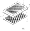
- FIGS. 5, 6 and 7, one application for drop-on-demand microvolume fluid dispensing is to deposit precise amounts of transfer liquid 24 into an array of wells in a microtitre plate 110, which is described in U.S. Patent No. 5,457,527, hereby incorporated by reference.
- the microtitre plate 110 is formed from two molded plastic plates 111 and 112.
- the upper plate 111 forms the side walls 113 of the multiple wells of the microtitre plate, and in the illustrative example, the wells are arranged in an 8x12 matrix, although matrices with other dimensions also work with the present invention.
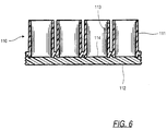
- the bottom plate 112 forms the bottom walls 114 of the matrix web, and is attached to the lower surface of to the lower surface of the upper plate by fusing the two plates together.
- the upper plate 111 is formed from an opaque polymeric material so that light cannot be transmitted therethrough.
- the lower plate 112 is formed of a transparent polymeric material so that it forms a transparent bottom wall 114 for each sample well. This permits viewing of sample material through the bottom wall 114, and also permits light emissions to be measured through the bottom wall.
- the transparent bottom walls 114 may also be used to expose the sample to light from an external excitation source, while leaving the tops of the wells unobstructed for maximum detection area.
- microvolume fluid dispensing system 10 can precisely dispense extremely small quantities of fluid, it is possible to utilize microtitre arrays 110 of correspondingly reduced dimensions.
- the difficulty of positioning the nozzle 63 directly over each well increases as the well diameter approaches the one millimeter range. In the case of a well diameter of one millimeter, it is desirable to position the nozzle 63 within 150 micrometers ( ⁇ M ) of the center of the well to permit accurate droplet shooting.
- the present invention utilizes a transparent bottom portion 112 of the microtitre plate array 110, which allows visible and infrared light to pass through the bottom of the microtitre array 110 into the well formed by the opaque side walls 113 of the microtitre plate array 111 and the transparent bottom walls 114 of the transparent bottom array 112.
- infrared light is passed through the transparent bottom section 112 of the microtitre plate array 110 onto the glass capillary 62 of the microdispenser 16.
- the light received at the microdispenser 16 is passed through the glass capillary 62 to an appropriate infrared detector (not shown) mounted on the glass capillary 62.
- the infrared light source in combination with the narrow well structure, provides a narrow beam of infrared light directed upward through each well, but not through an opaque material between the wells.
- the positioning robot uses these cues to reach and verify the position of the microdispenser.
- visible light is used in place of infrared light as described above.
- any visible wavelength of light can be used if the wells are devoid of liquid, or have clear liquids and a matching detector is used in place of the infrared detector.
- a greenish light at 300 nM can be passed through the microtitre plate 110 to the turbid liquid.
- a cryptate compound added to the liquid present in the well fluoresces in response to excitation by the greenish light.
- a detector that detects those red wavelengths is used in place of the infrared detector.
- the second preferred embodiment is more preferred than the first preferred embodiment when the number of microdispensers 212 employed is equal to or greater than eight because the second embodiment becomes more cost effective as the number of microdispensers 212 is increased.
- the first preferred embodiment is more preferred than the second preferred embodiment because the first embodiment becomes more cost effective when small numbers of microdispensers 212 are employed.
- the tradeoff occurs because in the second preferred embodiment a system liquid reservoir 214 is used to supply system liquid 20 to all the microdispensers 212, thus eliminating the separate pump and pressure sensor for each microdispenser 212 in the first preferred embodiment.
- first and second preferred embodiments are otherwise identical in structure and operation except as described herein. The precise number of microdispensers employed is a function of the user s dispensing requirements.
- the system liquid reservoir 214 receives system liquid 20, typically deionized water, through an intake tube 216 which contains a cap (not separately shown).
- the cap on the intake tube 216 is removed to enable the sealed system liquid reservoir 214 to receive system liquid 20 when the cap is off and seals the system liquid reservoir 214 shut when the cap is on so that the system liquid reservoir 214 can be maintained at a desired pressure.
- Pressure in the system liquid reservoir 214 is maintained by a pressure control system 218, through pressure control tubing 220.
- the pressure control system 218 includes an electrically controlled pump capable of accurately increasing or decreasing pressure in the system liquid reservoir 214.
- a pressure sensor 222 mounted on the system liquid reservoir 214 senses pressure in the system liquid reservoir 214 and transmits an electrical signal indicative of that pressure to a system controller 224 through electrical conductor 226.
- the system controller 224 contains a digital signal processor board and other electronics(not shown) which enable monitoring of various electrical signals, execution of control software code, and control of the microvolume liquid handling system 210.
- the system controller 224 electrically controls the pressure control system 218 through an electrical conductor 228 to adjust the pressure of the system liquid 20, and correspondingly, the pressure of the transfer liquid 24.
- a pressure relief valve 230 is mounted on the system liquid reservoir 214.
- the pressure relief valve 230 releases pressure from the system liquid reservoir 214 when the pressure exceeds a predetermined safety threshold.
- the pressure relief valve 230 can also be opened by the system controller 224 which is connected to the pressure relief valve 230 by a wire 232.
- the system controller 224 directs the pressure control system 218 to maintain one of three different pressure levels in the system reservoir 214 with regard to ambient atmospheric pressure.
- Each of the three pressure levels correspond to a different phase of operation of the microvolume liquid handling system 210.
- the three different pressure levels are a positive pressure, a high negative pressure and a low negative pressure.
- the positive pressure level Prior to dispensing, the positive pressure level is used for cleaning in order to flush the microdispenser free of any foreign matter in combination with resonant ultrasonic excitation of the microdispensers 212 in the manner described above.
- the high negative pressure level roughly 200 millibars less than the ambient atmospheric pressure, is used to aspirate transfer liquid 24 into the microdispensers 212.
- the low negative pressure level roughly -15 millibars, is used to supply back pressure to the transfer liquid 24 in the microdispensers 212 such that as droplets are dispensed, no additional transfer liquid 24 leaves the microdispensers 212.
- System liquid 20 in the system reservoir 214 is coupled to the microdispensers 212 through a distribution tube 234 that splits into a plurality of sections 236 as shown in FIG. 7, one section 236 is connected to each microdispenser 212.
- Attached to each of the distribution tube sections 236 are microvalves 242 and flow sensors 244.
- the microvalves 242 are micro-electromechanical machines ( MEMS ) that have the primary advantage of being sufficiently small so as to fit easily into the microvolume liquid handling system 210.
- the microvalves 242 are extremely precise valves used to control the movement of system liquid 20 and correspondingly, the amount of transfer liquid 24 that is dispensed.
- the system controller 224 sends electrical signals through an electrical connection 246 to control the microvalves 242.
- a flow sensor 244 is attached to each distribution tube section 236 to determine the amount of liquid that is being aspirated into each microdispenser associated with that flow sensor 244.
- the flow sensor 244 detects flow of system liquid 20 into or out of each microdispenser 212.
- the flow sensors 244 are each connected to the system controller 224 through an electrical conductor 248.
- the electrical conductor 248 carries electrical signals from each flow sensor 244 indicating not only the amount of liquid flow, but also the pressure in the distribution tube 234.
- the flow sensors 244 are also MEMS that have the primary advantage of being sufficiently small so as to fit easily into the microvolume liquid handling system 210, for example the flow sensors 244 described in IEEE Proceedings, MEMS 1995, publication number 0-7803-2503-6, entitled, A Differential Pressure Liquid Flow Sensor For Flow Regulation and Dosing Systems, by M. Boillat et al., hereby incorporated by reference.
- the robot 238 moves the microdispensers 212 to the next set of wells for further dispensing. Precise coordination of the robot s 238 movement is accomplished as described above with reference to the use of light passed through the bottom microtitre plate 112.
Abstract
Description
- The present invention relates to an apparatus and process for controlling, dispensing and measuring small quantities of fluid. More specifically, the present invention senses pressure changes to ascertain and confirm fluid volume dispensed and proper system functioning.
- Advances in industries employing chemical and biological processes have created a need for the ability to accurately and automatically dispense small quantities of fluids containing chemically or biologically active substances for commercial or experimental use. Accuracy and precision in the amount of fluid dispensed is important both from the standpoint of causing a desired reaction and minimizing the amount of materials used.
- Equipment for dispensing microvolumes of liquid have been demonstrated with technologies such as those developed for ink jet applications. However, ink jet equipment has the advantage of operating with a particular ink (or set of inks) of known and essentially fixed viscosity and other physical properties. Thus, because the properties of the ink being used are known and fixed, automatic ink jet equipment can be designed for the particular ink specified. Direct use of ink jet technology with fluids containing a particular chemical and biological substance of interest ("transfer liquid") is more problematic. Such transfer liquids have varying viscosity and other physical properties that make accurate microvolume dispensing difficult. Automatic microvolume liquid handling systems should be capable of handling fluids of varying viscosity and other properties to accommodate the wide range of substances they must dispense. Another aspect of this problem is the need to accommodate accurately dispensing smaller and smaller amounts of transfer liquid. Especially in the utilization and test of biological materials, it is desirable to reduce the amount of transfer liquid dispensed in order to save costs or more efficiently use a small amount of material available. It is often both desirable and difficult to accurately dispense microvolumes of transfer liquid containing biological materials. Knowing the amount of transfer liquid dispensed in every ejection of transfer liquid would be advantageous to an automated system.
- Another difficulty with dispensing microvolumes of transfer liquid arises due to the small orifices, e.g., 20-80 micrometers in diameter, employed to expel a transfer liquid. These small orifice sizes are susceptible to clogging. Heavy use of the nozzle promotes undesirable clogging by materials in the fluid being dispensed. Further exacerbating the clogging problem are the properties of the substances sometimes used in the transfer liquid. Clogging of transfer liquid substances at the orifice they are expelled from, or in other parts of the dispenser, can halt dispensing operations or make them far less precise. Therefore, it would be desirable to prevent or minimize clogging, be able to detect when such conditions are occurring, and to be able to automatically recover from these conditions. Failure of a microvolume dispenser to properly dispense transfer liquid can also be caused by other factors, such as air or other compressible gases being in the dispensing unit. It would be desirable to detect and indicate when a microvolume dispenser is either not dispensing at all, or not dispensing the desired microvolume ("misfiring").
- Over time it may be necessary to aspirate a variety of different fluid mixtures or solutions into the microvolume dispenser in order to dispense those fluids. Because each fluid may contaminate the microvolume dispenser with regard to a later-used fluid it is desirable to thoroughly clean a microdispenser when fluids are changed. Even when fluids are not changed, cleaning is necessary to prevent buildup of materials inside the microvolume dispenser. Unfortunately, using a pump alone to flush out the microvolume dispenser is not always 100% effective. Therefore, it would be desirable to be able to easily and thoroughly clean the microvolume dispenser from time to time.
- In order to achieve an automated microvolume dispensing system it would be desirable to ensure in realtime that the transfer liquid is within some given range of relevant system parameters in order to rapidly and accurately dispense transfer liquid droplets of substantially uniform size. For example, it is desirable to ensure that the transfer liquid is accurately deposited at its target surface. Because industry requires rapid dispensing of microvolume amounts of transfer liquid, it is also desirable to be able to ascertain transfer liquid volume dispensed, and to be able to detect and recover from dispensing problems in realtime.
- It is a primary object of the present invention to provide a microvolume liquid handling system which is capable of accurately verifying microvolume amounts of transfer liquid dispensed by sensing a corresponding change in pressure in the microvolume liquid handling system.
- It is also an object of the present invention to provide a microvolume liquid handling system which can accurately measure an amount of dispensed liquid regardless of transfer liquid properties such as viscosity.
- It is another object of the present invention to provide a microvolume liquid handling system which can transfer microvolume quantities of fluids containing chemically or biologically active substances.
- It is a further object of the present invention to provide a microvolume liquid handling system that prevents or minimizes clogging.
- It is still another object of the present invention to provide a microvolume liquid handling system which senses pressure changes associated with clogging and misfiring to indicate such improper operation.
- It is yet another object of the present invention to provide a microvolume liquid handling system which can verify that the transfer liquid is maintained within a given range of negative pressure (with respect to ambient atmospheric pressure) in order to accurately dispense microvolume amounts of transfer liquid and optimize the operation of the microdispenser.
- Other objects and advantages of the present invention will be apparent from the following detailed description.
- Accordingly, the foregoing objectives are realized in a first preferred embodiment by providing a microvolume liquid handling system which includes a positive displacement pump operated by a stepper motor, a piezoresistive pressure sensor, and an electrically controlled microdispenser that utilizes a piezoelectric transducer bonded to a glass capillary. The microdispenser is capable of rapidly and accurately dispensing subnanoliter ("nl") sized droplets by forcibly ejecting the droplets from a small nozzle, this is known asdrop-on-demand
 . The first embodiment is more preferred when four or fewer microdispensers are each coupled to a single positive displacement pump and pressure sensor.
- A second preferred embodiment of the microvolume liquid handling system, which is more preferred when the number of microdispensers employed is equal to or greater than eight, also realizes the foregoing objectives. The second preferred embodiment is similar to the first preferred embodiment, except that the positive displacement pump (which includes a valve as described below), the stepper motor, and the piezoresistive pressure sensor are replaced with a pressure control system for supplying system fluid and controlling system fluid pressure, a plurality of flow sensors for detecting fluid flow as well as pressure in the system fluid present in connecting tubing coupled to each microdispenser, and plurality of microfabricated valves, each microfabricated valve coupling each microdispenser to a system reservoir in the pressure control system.
- To provide the functionality of an automated liquid handling system, the microdispensers in both first and second preferred embodiments are mounted onto a 3-axis robotic system that is used to position the microdispensers at specific locations required to execute the desired liquid transfer protocol.
- The present invention includes a system liquid and a transfer liquid in the dispensing system separated by a known volume of air ("air gap") which facilitates measuring small changes in pressure in the system liquid that correlate to the volume of transfer liquid dispensed. The transfer liquid contains the substances being dispensed, while in one preferred embodiment the system liquid is deionized water. Each time a droplet in the microvolume dispensing range is dispensed, the transfer liquid will return to its prior position inside the microdispenser because of capillary forces, and the air gap's specific volume will be increased corresponding to the amount of transfer liquid dispensed. This has the effect of decreasing pressure in the system liquid line which is measured with a highly sensitive piezoresistive pressure sensor. The pressure sensor transmits an electric signal to control circuitry which converts the electric signal into a digital form and generates an indication of the corresponding volume of transfer liquid dispensed. An advantage of the present invention is its insensitivity to the viscosity of the transfer liquid. This is because the pressure change in the system liquid corresponds to the microvolume dispensed, without being dependent on the dispensed fluid viscosity. The present invention possesses unique capabilities in microvolume liquid handling. This system is capable of automatically sensing liquid surfaces, aspirating liquid to be transferred, and then dispensing small quantities of liquid with high accuracy, speed and precision. The dispensing is accomplished without the dispenser contacting the destination vessel or contents. A feature of the present invention is the capability to positively verify the microvolume of liquid that has been dispensed during realtime operation.
- Another aspect of the present invention prevents or minimizes clogging by activating the piezoelectric transducer at ultrasonic frequencies resonant with the microdispenser. By vibrating the microdispenser at its resonant ultrasonic frequency during aspiration of transfer liquid into the glass capillary, clogging is prevented or minimized. The piezoelectric transducer is also activated at the same resonant ultrasonic frequencies when the capillary is being cleaned. The resonant vibrations of the capillary during cleaning result in a cleaner glass capillary interior than previously achieved. Because the same structure is used to prevent clogging, break up existing clogs and clean the microdispenser, greater efficiencies are achieved than previously possible.
- Still another aspect of the present invention enables the microdispensers to be positioned with a high degree of accuracy with regard to wells of a microtitre plate. Visible or infrared light is transmitted through a transparent bottom half of a microtitre plate containing wells organized in rows and columns. Light does not pass through the opaque top half of the microtitre plate. When a particular microdispenser is moved from a position above the opaque top half of the microtitre plate to a position above the transparent bottom half of the microtitre plate, light passes through the glass capillary in the microdispenser where it is detected by a photodetector in optical contact with the glass capillary. The photodetector generates electronic signals corresponding to the amount of light received. The signals from the photodetector are coupled to a computer which uses the signals to help locate and verify the position of the microdispenser.
-
- FIG. 1 is a block diagram of the a microvolume liquid handling system illustrating the first embodiment of the present invention;
- FIG. 2 is a schematic of a positive displacement pump illustrating an aspect of the first embodiment of the present invention;
- FIG. 3 is side plan view of a microdispenser including a piezoelectric transducer;
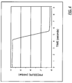
- FIG. 4 is a graph depicting the system line pressure during a microdispenser dispense illustrating operation of the present invention;
- FIG. 5 is an exploded perspective view of two halves of a microtitre plate prior to being joined, as used with the present invention;
- FIG. 6 is a sectional side plan view showing the two halves of the microtitre plate after having been joined in accordance with the present invention; and
- FIG. 7 is a block diagram of the a microvolume liquid handling system illustrating the second embodiment of the present invention;
- While the invention is susceptible to various modifications and alternative forms, specific embodiments thereof have been shown by way of example in the drawings and will herein be described in detail. It should be understood, however, that it is not intended to limit the invention to the particular forms disclosed. On the contrary, the intention is to cover all modifications, equivalents, and alternatives falling within the spirit and scope of the invention as defined by the appended claims.
- Turning now to the drawings and referring first to FIG. 1, a first embodiment of microvolume
liquid handling system 10 is illustrated. The microvolumeliquid handling system 10 includes apositive displacement pump 12, apressure sensor 14 and amicrodispenser 16.Tubing 18 connects thepositive displacement pump 12 to thepressure sensor 14 and thepressure sensor 14 to themicrodispenser 16. Thepositive displacement pump 12 moves a system liquid 20 through thepressure sensor 14 and themicrodispenser 16. After thesystem 10 is loaded with system liquid 20, anair gap 22 of known volume, then an amount oftransfer liquid 24, are drawn into themicrodispenser 16 in a manner described below. Thetransfer liquid 24 contains one or more biologically or chemically active substances of interest. In one preferred embodiment themicrodispenser 16 expels (or synonymously, "shoots") sub-nanoliter sizeindividual droplets 26 which are very reproducible. The expelleddroplets 26 oftransfer liquid 24 are on the order of 0.45 nanoliters perdroplet 26 in one preferred embodiment, but they can be as small as 5 picoliters. For example, if one desires to expel a total of 9 nanoliters oftransfer liquid 24, then themicrodispenser 16 will be directed to expel 20droplets 26.Droplet 26 size can be varied by varying the magnitude and duration of the electrical signal applied to themicrodispenser 16. Other factors affecting droplet size include: the size of the nozzle opening at the bottom of the microdispenser, the pressure at the microdispenser inlet, and properties of the transfer liquid. - Referring now to FIGS. 1 and 2, in one preferred embodiment the
positive displacement pump 12 is a XL 3000 Modular Digital Pump manufactured by Cavro Scientific Instruments, Inc., 242 Humboldt Court, Sunnyvale, California 94089. Thepositive displacement pump 12 includesstepper motor 28 and stepper motor 29, and asyringe 30. Thesyringe 30 includes aborosilicate glass tube 32 and aplunger 34 which is mechanically coupled through a series of gears and a belt (not shown) to thestepper motor 28.Stepper motor 28 motion causes theplunger 34 to move up or down by a specified number of discrete steps inside theglass tube 32. Theplunger 34 forms a fluidtight seal with theglass tube 32. In onepreferred embodiment syringe 30 has a usable capacity of 250 microliters which is the amount of system liquid 20 theplunger 34 can displace in one full stroke. Depending on the selected mode of operation, thestepper motor 28 is capable of making 3,000 or 12,000 discrete steps perplunger 34 full stroke. In one preferred embodiment thestepper motor 28 is directed to make 12,000 steps perfull plunger 34 stroke with each step displacing approximately 20.83 nanoliters ofsystem liquid 20. In one preferred embodiment the system liquid 20 utilized is deionized water. - Digitally encoded commands cause the
stepper motor 28 within thepositive displacement pump 12 to aspirate discrete volumes of liquid into themicrodispenser 16, wash themicrodispenser 16 between liquid transfers, and to control the pressure in the system liquid 20 line for microvolumeliquid handling system 10 operation. Thepositive displacement pump 12 is also used to prime thesystem 10 with system liquid 20 and to dispense higher volumes of liquid through themicrodispenser 16, allowing dilute solutions to be made. Thepositive displacement pump 12 can also work directly withtransfer liquid 24. Thus, if desired, transfer liquid 24 can be used assystem liquid 20 throughout the microvolumeliquid handling system 10. - To prime the microvolume
liquid handling system 10, thecontrol logic 42 first directs a 3-axisrobotic system 58 throughelectrical wire 56 to position themicrodispenser 16 over a wash station contained on therobotic system 58. In one preferred embodiment the microvolumeliquid handling system 10 includes, and is mounted on, a 3-axis robotic system is a MultiPROBE CR10100, manufactured by Packard Instrument Company, Downers Grove, Illinois. Thepositive displacement pump 12 includes avalve 38 for connecting asystem liquid reservoir 40 to thesyringe 30. An initialization control signal is transmitted through theelectrical cable 36 to thepump 12 bycontrol logic 42 which causes thevalve 38 to rotate connecting thesyringe 30 with thesystem fluid reservoir 40. The control signal also causes thestepper motor 28 to move theplunger 34 to its maximum extent up (Position 1 in FIG. 2) into theborosilicate glass tube 32. The next command from thecontrol logic 42 causes thestepper motor 28 to move theplunger 34 to its maximum extent down (Position 2 in FIG. 2) inside thetube 32, to extract system liquid 20 from thesystem reservoir 40. Another command from thecontrol logic 42 directs thevalve 38 to rotate again, causing thesyringe 30 to be connected with thetubing 18 connected to thepressure sensor 14. In one preferred embodiment thetubing 18 employed in the microvolumeliquid handling system 10 is Natural Color Teflon Tubing made by Zeus Industrial Products, Inc., Raritan, New Jersey, with an inner diameter of 0.059 inches and an outer diameter of 0.098 inches. The next command from thecontrol logic 42 to thepositive displacement pump 12 causes thesystem liquid 20 inside of thesyringe 30 to be pushed into the microvolumeliquid handling system 10 towards thepressure sensor 14. Because the microvolumeliquid handling system 10 typically requires about 4 milliliters of system fluid to be primed, the sequence of steps described above must be repeated about 16 times in order to completely prime the microvolumeliquid handling system 10. - The
control logic 42 receives signals from thepressure sensor 14 through anelectrical line 46. The signals are converted from an analog form into a digital form by an A/D (analog to digital)converter 44 and used by thecontrol logic 42 for processing and analysis. In one preferred embodiment the A/D conversion is a PC-LPM-16 Multifunction I/O Board manufactured by National Instruments Corporation, Austin, Texas. At various points in the liquid transfer process described herein, thecontrol logic 42 receives signals from thepressure transducer 14, and sends command signals to thepump 12,microdispenser electronics 51, and the 3-axisrobotic system 58. Within thecontrol logic 42 are the encoded algorithms that sequence the hardware (robotic system 58, pump 12, and microdispenser electronics 51) for specified liquid transfer protocols as described herein. Also within thecontrol logic 42 are the encoded algorithms that process the measured pressure signals to: verify and quantify microdispenses, perform diagnostics on the state of the microvolume liquid handling system, and automatically perform a calibration of the microdispenser for any selectedtransfer liquid 24. - The
pressure sensor 14 senses fluctuations in pressure associated with priming the microvolumeliquid handling system 10, aspiratingtransfer liquid 24 withpump 12, dispensingdroplets 26 withmicrodispenser 16, and washing ofmicrodispenser 16 usingpump 12. In one preferred embodiment thepressure sensor 14 is a piezoresistive pressure sensor part number 26PCDFG6G, from Microswitch, Inc., a Division of Honeywell, Inc., 11 West Spring Street, Freeport, Illinois 61032. Also included with thepressure sensor 14 in the block diagram in Figure 1 is electrical circuitry to amplify the analog pressure signal from the pressure sensor. Thepressure sensor 14 converts pressure into electrical signals which are driven to the A/D converter 44 and then used by thecontrol logic 42. For example, when the microvolumeliquid handling system 10 is being primed, thepressure sensor 14 will send electrical signals which will be analyzed by thecontrol logic 42 to determine whether they indicate any problems within the system such as partial or complete blockage in themicrodispenser 16. - Once the microvolume
liquid handling system 10 is primed, thecontrol logic 42 sends a signal throughelectrical wire 56 which instructs therobotic system 58 to position themicrodispenser 16 in air over thetransfer liquid 24. Thecontrol logic 42 instructsstepper motor 28 to move theplunger 34 down, aspirating a discrete quantity of air (air gap), e.g., 50 microliters in volume into themicrodispenser 16. Thecontrol logic 42 then instructs therobotic system 58 to move themicrodispenser 16 down until it makes contact with the surface of the transfer liquid 24 (not shown) is made. Contact of themicrodispenser 16 with the surface of thetransfer liquid 24 is determined by a capacitive liquid level sense system (U.S Patent Number 5,365,783). The microdispenser is connected byelectrical wire 55 to the liquidlevel sense electronics 54. When the liquidlevel sense electronics 54 detectsmicrodispenser 16 contact withtransfer liquid 24 surface, a signal is sent to therobotic system 58 throughelectrical wire 53 to stop downward motion. - The
control logic 42 next instructs thepump 12 to move theplunger 34 down in order to aspiratetransfer liquid 24 into themicrodispenser 16. The pressure signal is monitored bycontrol logic 42 during the aspiration to ensure that thetransfer liquid 24 is being successfully drawn into themicrodispenser 16. If a problem is detected, such as an abnormal drop in pressure due to partial or total blockage of the microdispenser, thecontrol logic 24 will send a stop movement command to thepump 12. Thecontrol logic 24 will then proceed with an encoded recovery algorithm. Note thattransfer liquid 24 can be drawn into the microvolumeliquid handling system 10 up to thepressure sensor 14 without threat of contaminating thepressure sensor 14. Additional tubing can be added to increasetransfer liquid 24 capacity. Once thetransfer liquid 24 has been aspirated into themicrodispenser 16, thecontrol logic 42 instructs therobotic system 58 to reposition themicrodispenser 16 above the chosen target, e.g., a microtitre plate. - In one preferred embodiment the
microdispenser 16 is the MD-K-130 Microdispenser Head manufactured by Microdrop, GmbH, Muhlenweg 143, D-22844 Norderstedt, Germany. - As illustrated in FIG. 3, the
microdispenser 16 consists of apiezoceramic tube 60 bonded to aglass capillary 62. The piezoceramic tube has aninner electrode 66 and anouter electrode 68 for receiving analog voltage pulses which cause the piezoceramic tube to constrict. Once theglass capillary 62 has been filled withtransfer liquid 24, thecontrol logic 42 directs themicrodispenserelectronics 51 byelectrical wire 50 to send analog voltage pulses to thepiezoelectric transducer 60 byelectrical wire 52. In one preferred embodiment themicrodispenserelectronics 51 is the MD-E-201 Drive Electronics manufactured by Microdrop, GmbH, Muhlenweg 143, D-22844 Norderstedt, Germany. Themicrodispenser electronics 51 control the magnitude and duration of the analog voltage pulses, and also the frequency at which the pulses are sent to themicrodispenser 16. Each voltage pulse causes a constriction of thepiezoelectric transducer 60, which in turn deforms theglass capillary 62. The deformation of theglass capillary 62 produces a pressure wave that propagates through thetransfer liquid 24 to themicrodispenser nozzle 63 where onedroplet 26 oftransfer liquid 24 is emitted under very high acceleration. The size of thesedroplets 26 has been shown to be very reproducible. The high acceleration of thetransfer liquid 24 minimizes or eliminates problems caused bytransfer liquid 24 surface tension and viscosity, allowing extremelysmall droplets 26 to be expelled from the nozzle, e.g., as small as 5picoliter droplets 26 have been demonstrated. Use of themicrodispenser 16 to propeldroplets 26 out of the nozzle also avoids problems encountered in a liquid transfer technique called touchoff. In the touchoff technique, adroplet 26 is held at the end of the nozzle and is deposited onto a target surface by bringing thatdroplet 26 into contact with the target surface while it is still hanging off of themicrodispenser 16. Such a contact process is made difficult by the surface tension, viscosity and wetting properties of themicrodispenser 16 and the target surface which lead to unacceptable volume deviations. The present invention avoids the problems of the contact process because thedroplets 26 are expelled out of themicrodispenser 16 at a velocity of several meters per second. The total desired volume is dispensed by the present invention by specifying the number ofdroplets 26 to be expelled. Because thousands ofdroplets 26 can be emitted per second from themicrodispenser 16, the desired microvolume oftransfer liquid 24 can rapidly be dispensed. - In one preferred embodiment, the lower section of the
glass capillary 62, between thepiezoelectric transducer 60 and thenozzle 63, is plated with a conductive material, either platinum or gold. This provides an electrically conductive path between the microdispenser 16 and the liquidlevel sense electronics 54. In one preferred embodiment theglass capillary 62 has an overall length of 73 millimeters, and thenozzle 63 has an internal diameter of 75 micrometers. - To dispense microvolume quantities of
transfer liquid 24, analog voltage pulses are sent to themicrodispenser 16, emittingdroplets 26 of liquid. Capillary forces acting on thetransfer liquid 24 replace the volume oftransfer liquid 24 emitted from themicrodispenser 16 with liquid from thetubing 18. However, since the transfer liquid-air gap-system liquid column terminates at a closed end in thepositive displacement pump 12, there is a corresponding drop in the system liquid 20 line pressure as theair gap 22 is expanded. This is illustrated in Figure 4 which depicts the pressure profile measured during a microdispense of 500 nanoliters. Important to the present invention, the magnitude of the pressure drop is a function of the size of theair gap 22 and the volume of the liquid dispensed. - With an
air gap 22 of known volume, the pressure change as detected by thepressure sensor 14 relates to the volume dispensed. Thus, thecontrol logic 42 determines from the pressure change measured by thepressure sensor 14, the volume oftransfer liquid 24 that was dispensed. In one preferred embodiment of the present invention it is preferable that the drop in pressure not exceed approximately 30 to 40 millibars below ambient pressure, depending on the properties of thetransfer liquid 24. If the amount oftransfer liquid 24 dispensed is sufficient to drop the pressure more than 30 to 40 millibars, the pressure difference across themicrodispenser 16, i.e., between the ambient pressure acting on thenozzle 63 and the pressure at thecapillary inlet 63, will be sufficient to force thetransfer liquid 24 up into thetubing 18. This will preclude further dispensing. There is a maximum amount oftransfer liquid 24 that can be dispensed before thecontrol logic 42 is required to command thepump 12 to advance theplunger 34 to compensate for the pressure drop. This maximum volume is determined by the desired dispense volume and the size of theair gap 22. Conversely, the size of theair gap 22 can be selected based on the desired dispense volume so as not to produce a pressure drop exceeding 30 to 40 millibars below ambient pressure. It is also within the scope of the present invention to advance theplunger 34 while themicrodispenser 16 is dispensing, thereby rebuilding system liquid 20 line pressure, so that themicrodispenser 16 can operate continuously. - The change in system liquid 20 pressure is used to determine that the desired amount of
transfer liquid 24 was dispensed. A second verification of the amount oftransfer liquid 24 that was dispensed is made by thecontrol logic 42 monitoring the system liquid 20 line pressure while directing thepump 12 to advance thesyringe plunger 34 upwards towardsPosition 1. Thesyringe plunger 34 is advanced until the system liquid 20 line pressure returns to the initial (pre-dispense) value. By thecontrol logic 42 tracking the displaced volume theplunger 34 moves (20.83 nanoliters perstepper motor 28 step), a second confirmation of dispensed volume is made, adding robustness to the system. The system liquid 20 line pressure is now at the correct value for thenext microdispenser 16 dispense, if a multi-dispense sequence has been specified. - Once the
transfer liquid 24 dispensing has been completed, thecontrol logic 24 causes therobotic system 58 to position themicrodispenser 16 over the wash station. Thecontrol logic 24 then directs pump 12 androbotic system 58 in a wash sequence that disposes of anytransfer liquid 24 left in themicrodispenser 16, and washes the internal surface ofglass capillary 62 and the external surface in thenozzle 63 area that was exposed to transferliquid 24. The wash fluid can either be system liquid 20 or any other liquid placed onto the deck of therobotic system 58. The wash sequence is designed to minimize cross-contamination ofsubsequent transfer liquids 24 with transfer liquids processed prior. Toward this end, it is also possible to enable an ultrasonic wash of themicrodispenser 16. This is accomplished by thecontrol logic 42 directing themicrodispenser electronics 51 to send electrical pulses to the microdispenser at a frequency in the ultrasonic range, e.g., 12 - 15 kilohertz (the preferred resonant frequency is believed to be approximately 12 kilohertz), that coincides with a resonant frequency of the microdispenser 16 -transfer liquid 24 system. Activating thepiezoelectric transducer 60 at ultrasonic frequencies resonant with theglass capillary 62 of themicrodispenser 16 causes the interior surfaces of theglass capillary 62 to vibrate vigorously. In both the first and second embodiments, system liquid 20 or a special cleaning and/or neutralizing fluid is used to flush out themicrodispenser 16 while thepiezoelectric transducer 60 is activated at resonant frequencies. Cleaning with resonant ultrasonic excitation has the effect of far more efficiently dislodging and eliminating matter adhering to themicrodispenser 16. For example, it has been shown in a number of test cases that ultrasonic excitation caused a 200% to 500% improvement (depending on the contaminant) in the reduction of residual matter left in themicrodispenser 16 as compared to cleaning without ultrasonic excitation. - Resonant ultrasonic excitation of the
microdispenser 16 also is used to prevent, minimize or alleviate clogging of the nozzle of the microdispenser. For example, when transfer liquid is being aspirated into themicrodispenser 16 it must pass through the relativelynarrow nozzle 63 in theglass capillary 62. Matter in thetransfer liquid 24 often comes into contact with the nozzles 63 surfaces permitting the matter to adhere to thenozzle 63, depending on the nature of the contact. In biochemical applications, one widely used matter added to thetransfer liquid 24 is polystyrene spheres. These spheres typically range from 1 µM to over 30 µM and may be uncoated or coated with magnetic ferrites, antigens or other materials. The relatively large size of the polystyrene spheres with regard tonozzle 63 diameter, in combination with their sometimes sticky coatings, can cause the spheres to adhere to thenozzle 63. It has been discovered that if thepiezoelectric transducer 60 is excited at the ultrasonic resonant frequency of themicrodispenser 16 while themicrodispenser 16 is being loaded (i.e.transfer liquid 24 is being aspirated in to the microdispenser 16) that clogging is prevented or less likely to occur. Thus, ultrasonic excitation of themicrodispenser 16 works to prevent or diminish clogging of thenozzle 63 by materials in thetransfer liquid 24. - Anytime a
transfer liquid 24 containing dissolved or suspended materials passes through thenozzle 63 there is a possibility of clogging. Accordingly, not only is clogging a problem during aspiration oftransfer liquid 24 into themicrodispenser 16 as described above, but it is also a problem when transfer liquid is dispensed from themicrodispenser 16. It has been discovered that periodic resonant ultrasonic excitation of themicrodispenser 16 between droplet dispensing by the piezoelectric transducer can reduce buildup of materials adhering to thenozzle 63 and thus prevent clogging in some instances. Even if substantial clogging does occur, resonant ultrasonic excitation of themicrodispenser 16 by thepiezoelectric transducer 60 will substantially clear the clogging materials from thenozzle 63. The key advantage here is that by preventing or eliminating clogging of thenozzle 63, the microvolumeliquid handling system 10 can continue operation without resort to extraordinary cleaning procedures and the delays associated with those procedures. In short, system downtime is reduced, thereby making the microvolumeliquid handling system 10 more efficient. - In the above description of the invention, the control of the
microdispenser 16 was effected by sending a specific number of electrical pulses from themicrodispenser electronics 51, each producing an emitteddroplet 26 oftransfer liquid 24. It is also within the scope of the invention to control themicrodispenser 16 by monitoring thepressure sensor 14 signal in realtime, and continuing to send electrical pulses to themicrodispenser 16 until a desired change in pressure is reached. In this mode of operation, the PC-LPM-16 Multifunction I/O Board that contains the A/D converter 44 is instructed bycontrol logic 42 to send electrical pulses to themicrodispenserelectronics 51. Each pulse sent by the Multifunction I/O Board results in one electrical pulse that is sent by themicrodispenser electronics 51 to themicrodispenser 16, emitting onedroplet 26 oftransfer liquid 24. Thecontrol logic 42 monitors thepressure sensor 14 signal as themicrodispenser 16 dispense is in progress, and once the desired change is pressure has been attained, thecontrol logic 42 directs the Multifunction I/O Board to stop sending electrical pulses. - This mode of operation is employed if a "misfiring" of
microdispenser 16 has been detected bycontrol logic 42. - It is also within the scope of the invention for the microvolume
liquid handling system 10 to automatically determine (calibrate) the size of the emitteddroplets 26 fortransfer liquids 24 of varying properties. As heretofore mentioned, emitteddroplet 26 size is affected by the properties of thetransfer liquid 24. Therefore, it is desirable to be able to automatically determine emitteddroplet 26 size so that the user need only specify the total transfer volume, and thesystem 10 will internally determine the number of emitteddroplets 26 required to satisfy the user request. In the encoded autocalibration algorithm, once thesystem 10 is primed, anair gap 22 and transfer liquid 24 aspirated, thecontrol logic 42 instructsmicrodispenser electronics 51 to send a specific number of electrical pulses, e.g., 1000, to themicrodispenser 16. The resulting drop inpressure sensor 14 signal is used bycontrol logic 42 to determine the volume oftransfer liquid 24 that was dispensed. This dispensed volume determination is verified by thecontrol logic 42 tracking the volume displaced by the movement of theplunger 34 to restore the system liquid 20 line pressure to the pre-dispense value. - The microvolume
liquid handling system 10 illustrated is FIG. 1 depicts asingle microdispenser 16,pressure sensor 14, and pump 12. It is within the spirit and scope of this invention to include embodiments of microvolume liquid handling systems that have a multiplicity (e.g., 4,8,96) ofmicrodispensers 16,pressure sensors 14, and pumps 12. It is also within the spirit and scope of this invention to include embodiments of microvolume liquid handling systems that have a multiplicity ofmicrodispensers 16,pressure sensors 14,valves 38, and one or more pumps 12. - Turning now to FIGS. 5, 6 and 7, one application for drop-on-demand microvolume fluid dispensing is to deposit precise amounts of
transfer liquid 24 into an array of wells in amicrotitre plate 110, which is described in U.S. Patent No. 5,457,527, hereby incorporated by reference. Themicrotitre plate 110 is formed from two moldedplastic plates upper plate 111 forms theside walls 113 of the multiple wells of the microtitre plate, and in the illustrative example, the wells are arranged in an 8x12 matrix, although matrices with other dimensions also work with the present invention. Thebottom plate 112 forms thebottom walls 114 of the matrix web, and is attached to the lower surface of to the lower surface of the upper plate by fusing the two plates together. Theupper plate 111 is formed from an opaque polymeric material so that light cannot be transmitted therethrough. In contrast to theupper plate 111, thelower plate 112 is formed of a transparent polymeric material so that it forms atransparent bottom wall 114 for each sample well. This permits viewing of sample material through thebottom wall 114, and also permits light emissions to be measured through the bottom wall. The transparentbottom walls 114 may also be used to expose the sample to light from an external excitation source, while leaving the tops of the wells unobstructed for maximum detection area. - In part because the present microvolume
fluid dispensing system 10 can precisely dispense extremely small quantities of fluid, it is possible to utilizemicrotitre arrays 110 of correspondingly reduced dimensions. The difficulty of positioning thenozzle 63 directly over each well increases as the well diameter approaches the one millimeter range. In the case of a well diameter of one millimeter, it is desirable to position thenozzle 63 within 150 micrometers (µM ) of the center of the well to permit accurate droplet shooting. The present invention utilizes a
transparent bottom portion 112 of themicrotitre plate array 110, which allows visible and infrared light to pass through the bottom of themicrotitre array 110 into the well formed by theopaque side walls 113 of themicrotitre plate array 111 and the transparentbottom walls 114 of the transparentbottom array 112. In one embodiment infrared light is passed through thetransparent bottom section 112 of themicrotitre plate array 110 onto theglass capillary 62 of themicrodispenser 16. The light received at themicrodispenser 16 is passed through theglass capillary 62 to an appropriate infrared detector (not shown) mounted on theglass capillary 62. The infrared light source, in combination with the narrow well structure, provides a narrow beam of infrared light directed upward through each well, but not through an opaque material between the wells. As the microdispenser is moved from one well to another it encounters a relatively dark zone indicating the dispenser is between wells, followed by a relatively bright zone indicating the edge of the next well is directly below. The positioning robot then uses these cues to reach and verify the position of the microdispenser. - In another preferred embodiment, visible light is used in place of infrared light as described above. For example, any visible wavelength of light can be used if the wells are devoid of liquid, or have clear liquids and a matching detector is used in place of the infrared detector. In the case where a turbid or cloudy liquid is present in the wells, a greenish light at 300 nM can be passed through the
microtitre plate 110 to the turbid liquid. A cryptate compound added to the liquid present in the well fluoresces in response to excitation by the greenish light. Cryptate fluoresces at approximately 620 and 650 nM, corresponding to red light. A detector that detects those red wavelengths is used in place of the infrared detector. - Turning now to FIG. 7, the second preferred embodiment of the microvolume
liquid handling system 210 is shown. The second preferred embodiment is more preferred than the first preferred embodiment when the number ofmicrodispensers 212 employed is equal to or greater than eight because the second embodiment becomes more cost effective as the number ofmicrodispensers 212 is increased. When the number ofmicrodispensers 212 employed is equal to or less than four, the first preferred embodiment is more preferred than the second preferred embodiment because the first embodiment becomes more cost effective when small numbers ofmicrodispensers 212 are employed. The tradeoff occurs because in the second preferred embodiment a systemliquid reservoir 214 is used to supplysystem liquid 20 to all themicrodispensers 212, thus eliminating the separate pump and pressure sensor for each microdispenser 212 in the first preferred embodiment. However, because the systemliquid reservoir 214 is more expensive to implement, it is more cost effective to employ the first embodiment when four or fewer microdispensers are employed. Note that first and second preferred embodiments are otherwise identical in structure and operation except as described herein. The precise number of microdispensers employed is a function of the users dispensing requirements. - With regard to the second preferred embodiment, the system
liquid reservoir 214 receivessystem liquid 20, typically deionized water, through anintake tube 216 which contains a cap (not separately shown). The cap on theintake tube 216 is removed to enable the sealed systemliquid reservoir 214 to receive system liquid 20 when the cap is off and seals the systemliquid reservoir 214 shut when the cap is on so that the systemliquid reservoir 214 can be maintained at a desired pressure. Pressure in the systemliquid reservoir 214 is maintained by apressure control system 218, throughpressure control tubing 220. Thepressure control system 218 includes an electrically controlled pump capable of accurately increasing or decreasing pressure in the systemliquid reservoir 214. Apressure sensor 222 mounted on the systemliquid reservoir 214 senses pressure in the systemliquid reservoir 214 and transmits an electrical signal indicative of that pressure to asystem controller 224 throughelectrical conductor 226. Thesystem controller 224 contains a digital signal processor board and other electronics(not shown) which enable monitoring of various electrical signals, execution of control software code, and control of the microvolumeliquid handling system 210. Thesystem controller 224 electrically controls thepressure control system 218 through anelectrical conductor 228 to adjust the pressure of thesystem liquid 20, and correspondingly, the pressure of thetransfer liquid 24. Apressure relief valve 230 is mounted on the systemliquid reservoir 214. Thepressure relief valve 230 releases pressure from the systemliquid reservoir 214 when the pressure exceeds a predetermined safety threshold. In one embodiment, thepressure relief valve 230 can also be opened by thesystem controller 224 which is connected to thepressure relief valve 230 by awire 232. - During operations, the
system controller 224 directs thepressure control system 218 to maintain one of three different pressure levels in thesystem reservoir 214 with regard to ambient atmospheric pressure. Each of the three pressure levels correspond to a different phase of operation of the microvolumeliquid handling system 210. The three different pressure levels are a positive pressure, a high negative pressure and a low negative pressure. Prior to dispensing, the positive pressure level is used for cleaning in order to flush the microdispenser free of any foreign matter in combination with resonant ultrasonic excitation of themicrodispensers 212 in the manner described above. After themicrodispensers 212 are relatively clean, the high negative pressure level, roughly 200 millibars less than the ambient atmospheric pressure, is used to aspiratetransfer liquid 24 into themicrodispensers 212. Once thetransfer liquid 24 has been aspirated into themicrodispensers 212, the low negative pressure level, roughly -15 millibars, is used to supply back pressure to thetransfer liquid 24 in themicrodispensers 212 such that as droplets are dispensed, noadditional transfer liquid 24 leaves themicrodispensers 212. -
System liquid 20 in thesystem reservoir 214 is coupled to themicrodispensers 212 through adistribution tube 234 that splits into a plurality ofsections 236 as shown in FIG. 7, onesection 236 is connected to eachmicrodispenser 212. Attached to each of thedistribution tube sections 236 aremicrovalves 242 and flowsensors 244. Themicrovalves 242 are micro-electromechanical machines (MEMS) that have the primary advantage of being sufficiently small so as to fit easily into the microvolumeliquid handling system 210. Themicrovalves 242 are extremely precise valves used to control the movement of system liquid 20 and correspondingly, the amount oftransfer liquid 24 that is dispensed. Thesystem controller 224 sends electrical signals through anelectrical connection 246 to control themicrovalves 242. Aflow sensor 244 is attached to eachdistribution tube section 236 to determine the amount of liquid that is being aspirated into each microdispenser associated with thatflow sensor 244. Theflow sensor 244 detects flow of system liquid 20 into or out of eachmicrodispenser 212. Theflow sensors 244 are each connected to thesystem controller 224 through anelectrical conductor 248. Theelectrical conductor 248 carries electrical signals from eachflow sensor 244 indicating not only the amount of liquid flow, but also the pressure in thedistribution tube 234. Theflow sensors 244 are also MEMS that have the primary advantage of being sufficiently small so as to fit easily into the microvolumeliquid handling system 210, for example theflow sensors 244 described in IEEE Proceedings, MEMS 1995, publication number 0-7803-2503-6, entitled, A Differential Pressure Liquid Flow Sensor For Flow Regulation and Dosing Systems, by M. Boillat et al., hereby incorporated by reference. - The
distribution tube 234, which is physically connected to themicrodispensers 212, is attached to a threeaxis robot 238, as in the first preferred embodiment, which correspondingly relocates themicrodispensers 212 to positions abovedifferent microtitre plate 110 wells. After the desired number of droplets has been dispensed into each well, therobot 238 moves themicrodispensers 212 to the next set of wells for further dispensing. Precise coordination of the robots 238 movement is accomplished as described above with reference to the use of light passed through thebottom microtitre plate 112.
Claims (18)
- A microvolume liquid handling system for dispensing small quantities of liquids, comprising:a pump for pumping a liquid;a microdispenser for dispensing microvolumes of said liquid;a pressure sensor for converting pressure changes in said into a signal; tubing for connecting said pump to said pressure sensor and said pressure sensor to said microdispenser; andcontrol logic for converting the signal into an indication of liquid volume dispensed.
- The microvolume liquid handling system of claim 1 wherein said liquid is divided into a first part and a second part separated by a compressible area.
- The microvolume liquid handling system of claim 1 wherein said microdispenser produces discrete, substantially reproducibly sized droplets that are less than one nanoliter in volume.
- The microvolume liquid handling system of claim 1 wherein said pump further comprises a valve for coupling said pressure sensor to a syringe, said syringe capable of pumping said first liquid into said pressure sensor and said microdispenser.
- The microvolume liquid handling system of claim 1 wherein said indication of liquid volume dispensed is used to control liquid dispensing from said microdispenser.
- The microvolume liquid handling system of claim 1 wherein said microdispenser further comprises a microdispenser with a nozzle for emitting droplets of said liquid.
- The microvolume liquid handling system of claim 1 wherein said pressure sensor contains a piezoresistive element capable of converting pressure into an electrical signal.
- The microvolume liquid handling systems of claim 1 wherein said means for dispensing further comprise a capillary and a piezoelectric transducer in substantially radial contact with a portion of said capillary.
- The microvolume liquid handling system of claim 1 wherein said microdispenser is mounted on a robotic system capable of moving said microdispenser.
- The microvolume liquid handling system of claim 9 wherein said robotic system is a three-axis system.
- The microvolume liquid handling system of claim 1, further comprising:a microtitre plate having an array of wells disposed therein, said wells have a bottom portion transparent light, said bottom portion forming bottom walls of said wells, and a top portion opaque to light, said top portion having gaps that form side walls of the wells;a light source for emitting light adjacent to said bottom portion of said microtitre plate such that said light is transmitted through said transparent bottom portion and through said gaps in said top portion of said microtitre plate;a light sensor for sensing said light passing through said wells of said microtitre plate and producing a corresponding light signal when said light is sensed; andwherein said control logic is electrically coupled to said light sensor for receiving said light signal, said control logic being electrically coupled to a robot, and said control logic directing said robot to position said microdispenser to a desired position above said top portion of said microtitre plate in responsive to said light signal to dispense one or more droplets into one of said wells.
- The microwave liquid handling system of claim 1, wherein said pump further comprises:a system liquid reservoir containing said liquid coupled to said pump; andwherein said pump is capable of increasing or decreasing pressure of said liquid in said system reservoir.
- A process for preventing contamination of a microvolume liquid handling system, said microvolume liquid handling system including a pump for pumping a liquid, a microdispenser for dispensing microvolumes of said liquid, a pressure sensor for converting pressure changes said liquid into a signal, tubing for connecting said pump to said pressure sensor and said pressure sensor to said microdispenser, and control logic for converting the signal into an indication of liquid volume dispensed, said microdispenser having a capillary portion for dispensing droplets and a constricting portion for constricting said capillary portion, comprising the steps of:activating said constricting portion at a high frequency sufficient to dislodge foreign material adhering to interior surfaces of said capillary portion, said foreign material being dislodged into a liquid in said capillary portion.
- The process for preventing contamination of a microvolume liquid handling system of claim 13, wherein said high frequency is approximately a resonant frequency of said microdispenser.
- The process for preventing contamination of a microvolume liquid handling system of claim 13, further comprising the steps of:bringing said nozzle and a source said liquid containing foreign matter into operational contact;aspirating said liquid through said nozzle into said capillary portion of said microdispenser; andwherein said activating step occurs at a frequency approximately resonant with said microdispenser.
- The process for preventing contamination of a microvolume liquid handling system of claim 13, further comprising:a system liquid reservoir containing a system liquid coupled to said pump; andwherein said pump is capable of increasing or decreasing pressure of said system liquid in said system liquid.
- The process for preventing contamination of a microvolume liquid handling system of claim 13,
wherein said frequency is approximately a resonant ultrasonic frequency of said microdispenser. - The process for preventing contamination of a microvolume liquid handling system of claim 13, further comprising the steps of:moving said microdispenser adjacent to a microtitre plate having an array of wells disposed therein, said wells have a bottom portion transparent to light, said bottom portion forming bottom walls of said wells, and a top portion opaque to light, said top portion having gaps that form side walls of the wells;emitting a light from a light source to said bottom portion of said microtitre plate such that said light is transmitted through said transparent bottom portion and through said gaps in said top portion of said microtitre plate;controlling said movement of said microdispenser with an system controller, said system controller being electrically coupled to said light sensor for receiving said light signal, said system controller being electrically coupled to said robot, and said system controller directing said robot to position said microdispenser at a desired position above said top portion of said microtitre plate in response to said light signal to dispense one or more droplets from said nozzle of said microdispenser into one of said wells.
Applications Claiming Priority (4)
| Application Number | Priority Date | Filing Date | Title |
|---|---|---|---|
| US65645596A | 1996-05-31 | 1996-05-31 | |
| US656455 | 1996-05-31 | ||
| US4186197P | 1997-04-08 | 1997-04-08 | |
| US41861P | 1997-04-08 |
Publications (3)
| Publication Number | Publication Date |
|---|---|
| EP0810438A2 true EP0810438A2 (en) | 1997-12-03 |
| EP0810438A3 EP0810438A3 (en) | 1998-09-30 |
| EP0810438B1 EP0810438B1 (en) | 2004-02-04 |
Family
ID=26718622
Family Applications (1)
| Application Number | Title | Priority Date | Filing Date |
|---|---|---|---|
| EP97108726A Expired - Lifetime EP0810438B1 (en) | 1996-05-31 | 1997-05-30 | Microvolume liquid handling system |
Country Status (4)
| Country | Link |
|---|---|
| EP (1) | EP0810438B1 (en) |
| JP (2) | JP4095135B2 (en) |
| AT (1) | ATE259068T1 (en) |
| DE (1) | DE69727422T2 (en) |
Cited By (37)
| Publication number | Priority date | Publication date | Assignee | Title |
|---|---|---|---|---|
| WO1999030170A1 (en) * | 1997-12-05 | 1999-06-17 | Bayer Corporation | Method of verifying aspirated volume in automatic diagnostic system |
| WO1999030168A1 (en) * | 1997-12-05 | 1999-06-17 | MAX-PLANCK-Gesellschaft zur Förderung der Wissenschaften e.V. | Device and method for electrically triggered micro drop delivery |
| WO1999040444A1 (en) * | 1998-02-06 | 1999-08-12 | Bio-Magnetics Ltd. | A device and system for transfer of material |
| FR2776389A1 (en) * | 1998-03-20 | 1999-09-24 | Fondation Jean Dausset Ceph | Automated apparatus, useful for preparation of a large number of reaction samples in nano-volumes |
| WO1999051977A1 (en) * | 1998-04-06 | 1999-10-14 | MAX-PLANCK-Gesellschaft zur Förderung der Wissenschaften e.V. | Device and method for collecting samples in polymer support materials |
| WO2000033087A1 (en) * | 1998-12-03 | 2000-06-08 | Bayer Corporation | Method and apparatus for aspirating and dispensing sample fluids |
| EP1007973A2 (en) * | 1997-04-08 | 2000-06-14 | Packard Instrument Company, Inc. | Microvolume liquid handling system |
| WO2000033961A1 (en) * | 1998-12-10 | 2000-06-15 | Aurora Biosciences Corporation | Fluid dispenser and dispensing methods |
| US6121049A (en) * | 1997-12-05 | 2000-09-19 | Bayer Corporation | Method of verifying aspirated volume in automatic diagnostic system |
| EP1044072A1 (en) * | 1998-01-09 | 2000-10-18 | Cartesian Technology Inc. | Method and apparatus for high-speed dot array dispensing |
| EP1072313A2 (en) * | 1999-07-24 | 2001-01-31 | Max-Planck-Gesellschaft zur Förderung der Wissenschaften e.V. | Method and device for pipetting liquids |
| WO2001023092A1 (en) * | 1999-09-28 | 2001-04-05 | Giesing, Michael | Device and method for absorbing and releasing minute amounts of liquid |
| US6280148B1 (en) | 1997-02-19 | 2001-08-28 | Hahn-Schickard-Gesellschaft Fur Angewandte Forschung | Microdosing device and method for operating same |
| EP1160573A2 (en) * | 2000-05-31 | 2001-12-05 | Infineon Technologies AG | Microtitre plate and coupled multiple pipettor |
| EP1181100A1 (en) * | 1999-05-03 | 2002-02-27 | LJL Biosystems, Inc. | Integrated sample-processing system |
| EP1231957A1 (en) * | 1999-09-14 | 2002-08-21 | Pharmacopeia Inc. | Flow control elements for use in liquid dispensers |
| WO2002070999A2 (en) * | 2001-02-02 | 2002-09-12 | Packard Instrument Company, Inc. | Method and apparatus for dispensing micridoplets |
| WO2003103827A1 (en) * | 2002-06-11 | 2003-12-18 | Basf Aktiengesellschaft | Reactor system for carrying out chemical reactions in parallel, in particular polymerisation reactions |
| EP1424130A2 (en) * | 2002-11-26 | 2004-06-02 | CyBio AG | Multichannel dispenser with automatic calibration |
| US6838051B2 (en) | 1999-05-03 | 2005-01-04 | Ljl Biosystems, Inc. | Integrated sample-processing system |
| US6902703B2 (en) | 1999-05-03 | 2005-06-07 | Ljl Biosystems, Inc. | Integrated sample-processing system |
| US7135146B2 (en) | 2000-10-11 | 2006-11-14 | Innovadyne Technologies, Inc. | Universal non-contact dispense peripheral apparatus and method for a primary liquid handling device |
| US7169616B2 (en) | 2002-01-25 | 2007-01-30 | Innovadyne Technologies, Inc. | Method of purging trapped gas from a system fluid contained in an actuation valve |
| DE102005060862B3 (en) * | 2005-12-20 | 2007-06-28 | Stratec Biomedical Systems Ag | Assessing dosing performance of pipette connected to metering pump comprises determining pressure-time plot and comparing it with target plot of pump speed or power |
| US7470547B2 (en) | 2003-07-31 | 2008-12-30 | Biodot, Inc. | Methods and systems for dispensing sub-microfluidic drops |
| US7497995B2 (en) | 2000-10-11 | 2009-03-03 | Innovadyne Technologies, Inc. | Hybrid valve apparatus and method for fluid handling |
| EP2295987A1 (en) * | 2008-07-02 | 2011-03-16 | Beckman Coulter, Inc. | Dispensing device |
| CN102470367A (en) * | 2009-10-29 | 2012-05-23 | 浦项工科大学校产学协力团 | Liquid droplet ejection apparatus |
| CN102757006A (en) * | 2011-07-18 | 2012-10-31 | 英特莱波公司 | Method and device for solution weight and continuous distribution |
| US8920752B2 (en) | 2007-01-19 | 2014-12-30 | Biodot, Inc. | Systems and methods for high speed array printing and hybridization |
| US9068566B2 (en) | 2011-01-21 | 2015-06-30 | Biodot, Inc. | Piezoelectric dispenser with a longitudinal transducer and replaceable capillary tube |
| EP2802848A4 (en) * | 2012-01-11 | 2015-11-04 | Siemens Healthcare Diagnostics | Liquid transfer systems and methods of calibration thereof |
| US9696328B2 (en) | 2002-05-17 | 2017-07-04 | Becton, Dickinson And Company | Automated system for isolating, amplifying and detecting a target nucleic acid sequence |
| WO2017125499A1 (en) * | 2016-01-22 | 2017-07-27 | Elvesys | System for measuring the flow rate of a liquid and use of same |
| CN109420216A (en) * | 2017-08-31 | 2019-03-05 | 贝克顿·迪金森公司 | Reservoir with low volume sensor |
| CN112174080A (en) * | 2019-04-26 | 2021-01-05 | 费斯托股份两合公司 | Dosing unit and method for dosing liquids |
| EP2914950B1 (en) * | 2012-11-01 | 2023-01-04 | Leica Biosystems Melbourne Pty Ltd | An automated slide treatment apparatus |
Families Citing this family (22)
| Publication number | Priority date | Publication date | Assignee | Title |
|---|---|---|---|---|
| US6203759B1 (en) | 1996-05-31 | 2001-03-20 | Packard Instrument Company | Microvolume liquid handling system |
| US6537817B1 (en) | 1993-05-31 | 2003-03-25 | Packard Instrument Company | Piezoelectric-drop-on-demand technology |
| US6521187B1 (en) * | 1996-05-31 | 2003-02-18 | Packard Instrument Company | Dispensing liquid drops onto porous brittle substrates |
| DE10017105A1 (en) * | 2000-04-06 | 2001-10-11 | Basf Ag | Method and device for producing biopolymer fields |
| CH695544A5 (en) * | 2000-11-17 | 2006-06-30 | Tecan Trading Ag | Apparatus for dispensing or aspirating / dispensing liquid samples. |
| JP2003254983A (en) * | 2002-03-05 | 2003-09-10 | Sakae:Kk | Level detection apparatus and automatic analyzer using the same |
| US6932502B2 (en) * | 2002-05-01 | 2005-08-23 | Hewlett-Packard Development Company, L.P. | Mixing apparatus |
| JP4077256B2 (en) * | 2002-07-09 | 2008-04-16 | 株式会社マイクロジェット | Discharge device and injection device |
| US7727752B2 (en) | 2003-07-29 | 2010-06-01 | Life Technologies Corporation | Kinase and phosphatase assays |
| TWI422801B (en) * | 2005-05-19 | 2014-01-11 | Universal Bio Research Co Ltd | Method of detecting dispensed quantity and liquid draw monitoring type dispensing device |
| JP2007315949A (en) * | 2006-05-26 | 2007-12-06 | Toshiba Corp | Automatic analyzer |
| US8015939B2 (en) | 2006-06-30 | 2011-09-13 | Asml Netherlands B.V. | Imprintable medium dispenser |
| JP4957957B2 (en) * | 2006-11-15 | 2012-06-20 | 横河電機株式会社 | Liquid supply device |
| US9304141B2 (en) | 2007-04-18 | 2016-04-05 | Becton, Dickinson And Company | Method and apparatus for determing dispense volume |
| DE102008016513B4 (en) * | 2008-03-31 | 2012-12-20 | Bartels Mikrotechnik Gmbh | Device and method for exact dosing of liquids |
| DE102009050782B4 (en) | 2008-10-29 | 2020-06-10 | Korea Institute Of Machinery & Materials | Hollow, actuator-driven droplet dispenser |
| KR101093686B1 (en) * | 2008-10-29 | 2011-12-15 | 한국기계연구원 | Hollow Type Actuator Driven Droplet Dispensing Apparatus |
| EP2213364A1 (en) * | 2009-01-30 | 2010-08-04 | Albert-Ludwigs-Universität Freiburg | Phase guide patterns for liquid manipulation |
| JP5034016B2 (en) * | 2009-01-30 | 2012-09-26 | 矢部川電気工業株式会社 | Fluid transfer device, fluid transfer method, program, and recording medium |
| JP5453375B2 (en) * | 2011-11-07 | 2014-03-26 | 株式会社東芝 | Automatic analyzer |
| JP2013061356A (en) * | 2013-01-08 | 2013-04-04 | Toshiba Corp | Automatic analyzer |
| JP7055878B2 (en) * | 2017-12-19 | 2022-04-18 | シーメンス・ヘルスケア・ダイアグノスティックス・インコーポレイテッド | Probe device, assembly, and method for suctioning and dispensing liquids |
Citations (7)
| Publication number | Priority date | Publication date | Assignee | Title |
|---|---|---|---|---|
| EP0169071A2 (en) * | 1984-07-19 | 1986-01-22 | EASTMAN KODAK COMPANY (a New Jersey corporation) | Apparatus and method for detecting liquid penetration by a container used for aspirating and dispensing the liquid |
| EP0268237A2 (en) * | 1986-11-17 | 1988-05-25 | Abbott Laboratories | Apparatus and process for reagent fluid dispensing and printing |
| US4777832A (en) * | 1985-11-18 | 1988-10-18 | Chemila S R L | Liquid level sensor, used in an automatic station for preparing immunologic dosages |
| JPH01234144A (en) * | 1988-03-15 | 1989-09-19 | Nagao Saito | Ultrasonic machining vibrator |
| EP0438136A2 (en) * | 1990-01-18 | 1991-07-24 | Mochida Pharmaceutical Co., Ltd. | Automated dispensing and diluting system |
| EP0508531A2 (en) * | 1991-04-10 | 1992-10-14 | Johnson & Johnson Clinical Diagnostics, Inc. | Liquid dispensing using container bottom sensing |
| EP0545284A1 (en) * | 1991-11-29 | 1993-06-09 | Canon Kabushiki Kaisha | Sample measuring device and sample measuring system |
Family Cites Families (10)
| Publication number | Priority date | Publication date | Assignee | Title |
|---|---|---|---|---|
| JPS60107744U (en) * | 1983-12-26 | 1985-07-22 | オリンパス光学工業株式会社 | Dispensing machine |
| JPS60145345U (en) * | 1984-03-07 | 1985-09-26 | 株式会社島津製作所 | liquid sample syringe |
| SE448031B (en) * | 1985-06-18 | 1987-01-12 | Scomas Ab | PROCEDURE AND APPARATUS FOR INDICATING THE DETECTION OF PIPETTE POSITIONS AT A TEST PLATE |
| JPS6315121A (en) * | 1986-07-07 | 1988-01-22 | Tosoh Corp | Liquid quantitative take-out apparatus |
| CA1302979C (en) * | 1986-10-24 | 1992-06-09 | Richard W. Hanaway | Multiple pipette sampler |
| JP3246752B2 (en) * | 1991-02-13 | 2002-01-15 | オリンパス光学工業株式会社 | Dispensing nozzle cleaning device |
| JPH07213926A (en) * | 1994-02-03 | 1995-08-15 | Hitachi Koki Co Ltd | Pipette |
| JPH07243949A (en) * | 1994-03-03 | 1995-09-19 | Olympus Optical Co Ltd | Dispensing nozzle washing device for medical analyzer |
| JPH07287021A (en) * | 1994-04-19 | 1995-10-31 | Hitachi Ltd | Automatic distribution apparatus |
| JP3532626B2 (en) * | 1994-10-07 | 2004-05-31 | アロカ株式会社 | Stirring nozzle device |
-
1997
- 1997-05-30 EP EP97108726A patent/EP0810438B1/en not_active Expired - Lifetime
- 1997-05-30 AT AT97108726T patent/ATE259068T1/en not_active IP Right Cessation
- 1997-05-30 DE DE69727422T patent/DE69727422T2/en not_active Expired - Lifetime
- 1997-06-02 JP JP14392197A patent/JP4095135B2/en not_active Expired - Lifetime
-
2007
- 2007-11-28 JP JP2007307569A patent/JP4783776B2/en not_active Expired - Lifetime
Patent Citations (7)
| Publication number | Priority date | Publication date | Assignee | Title |
|---|---|---|---|---|
| EP0169071A2 (en) * | 1984-07-19 | 1986-01-22 | EASTMAN KODAK COMPANY (a New Jersey corporation) | Apparatus and method for detecting liquid penetration by a container used for aspirating and dispensing the liquid |
| US4777832A (en) * | 1985-11-18 | 1988-10-18 | Chemila S R L | Liquid level sensor, used in an automatic station for preparing immunologic dosages |
| EP0268237A2 (en) * | 1986-11-17 | 1988-05-25 | Abbott Laboratories | Apparatus and process for reagent fluid dispensing and printing |
| JPH01234144A (en) * | 1988-03-15 | 1989-09-19 | Nagao Saito | Ultrasonic machining vibrator |
| EP0438136A2 (en) * | 1990-01-18 | 1991-07-24 | Mochida Pharmaceutical Co., Ltd. | Automated dispensing and diluting system |
| EP0508531A2 (en) * | 1991-04-10 | 1992-10-14 | Johnson & Johnson Clinical Diagnostics, Inc. | Liquid dispensing using container bottom sensing |
| EP0545284A1 (en) * | 1991-11-29 | 1993-06-09 | Canon Kabushiki Kaisha | Sample measuring device and sample measuring system |
Non-Patent Citations (1)
| Title |
|---|
| PATENT ABSTRACTS OF JAPAN vol. 013, no. 560 (M-906), 13 December 1989 (1989-12-13) & JP 01 234144 A (NAGAO SAITO;OTHERS: 01), 19 September 1989 (1989-09-19) * |
Cited By (68)
| Publication number | Priority date | Publication date | Assignee | Title |
|---|---|---|---|---|
| US6158269A (en) * | 1995-07-13 | 2000-12-12 | Bayer Corporation | Method and apparatus for aspirating and dispensing sample fluids |
| US6280148B1 (en) | 1997-02-19 | 2001-08-28 | Hahn-Schickard-Gesellschaft Fur Angewandte Forschung | Microdosing device and method for operating same |
| EP1007973A2 (en) * | 1997-04-08 | 2000-06-14 | Packard Instrument Company, Inc. | Microvolume liquid handling system |
| EP1007973B1 (en) * | 1997-04-08 | 2004-12-01 | Packard Instrument Company, Inc. | Microvolume liquid handling system |
| US6121049A (en) * | 1997-12-05 | 2000-09-19 | Bayer Corporation | Method of verifying aspirated volume in automatic diagnostic system |
| WO1999030170A1 (en) * | 1997-12-05 | 1999-06-17 | Bayer Corporation | Method of verifying aspirated volume in automatic diagnostic system |
| US6060320A (en) * | 1997-12-05 | 2000-05-09 | Bayer Corporation | Method of verifying aspirated volume in automatic diagnostic system |
| US6599479B1 (en) | 1997-12-05 | 2003-07-29 | Max-Planck-Gesellschaft Zur Forderung Der Wissenschaften E.V. | Device and procedure for the electrically triggered microdrop release with a dispensing head |
| EP1508808A3 (en) * | 1997-12-05 | 2005-08-03 | Max-Planck-Gesellschaft zur Förderung der Wissenschaften e.V. | Method and Apparatus for electrically actuated dispensing of microdrops |
| WO1999030168A1 (en) * | 1997-12-05 | 1999-06-17 | MAX-PLANCK-Gesellschaft zur Förderung der Wissenschaften e.V. | Device and method for electrically triggered micro drop delivery |
| EP1508808A2 (en) | 1997-12-05 | 2005-02-23 | Max-Planck-Gesellschaft zur Förderung der Wissenschaften e.V. | Method and Apparatus for electrically actuated dispensing of microdrops |
| EP1044072A1 (en) * | 1998-01-09 | 2000-10-18 | Cartesian Technology Inc. | Method and apparatus for high-speed dot array dispensing |
| EP1044072A4 (en) * | 1998-01-09 | 2002-11-27 | Cartesian Technology Inc | Method and apparatus for high-speed dot array dispensing |
| WO1999040444A1 (en) * | 1998-02-06 | 1999-08-12 | Bio-Magnetics Ltd. | A device and system for transfer of material |
| US6409925B1 (en) | 1998-02-06 | 2002-06-25 | Bio-Magnetics Ltd. | Device and system for transfer of material |
| FR2776389A1 (en) * | 1998-03-20 | 1999-09-24 | Fondation Jean Dausset Ceph | Automated apparatus, useful for preparation of a large number of reaction samples in nano-volumes |
| WO1999049320A1 (en) * | 1998-03-20 | 1999-09-30 | Fondation Jean Dausset-Ceph | Automatic device for producing samples for use in chemical or biological reactions in liquid medium |
| US6893611B1 (en) | 1998-03-20 | 2005-05-17 | Fondation Jean Dausset-Ceph | Automatic device for dispensing samples in liquid medium for use in chemical or biological reactions |
| US6991714B1 (en) | 1998-04-06 | 2006-01-31 | Max-Planck-Gesellschaft Zur Foederung Der Wissenschaften E.V. | Apparatus and method for taking samples from polymer support material |
| WO1999051977A1 (en) * | 1998-04-06 | 1999-10-14 | MAX-PLANCK-Gesellschaft zur Förderung der Wissenschaften e.V. | Device and method for collecting samples in polymer support materials |
| WO2000033087A1 (en) * | 1998-12-03 | 2000-06-08 | Bayer Corporation | Method and apparatus for aspirating and dispensing sample fluids |
| US6296811B1 (en) | 1998-12-10 | 2001-10-02 | Aurora Biosciences Corporation | Fluid dispenser and dispensing methods |
| WO2000033961A1 (en) * | 1998-12-10 | 2000-06-15 | Aurora Biosciences Corporation | Fluid dispenser and dispensing methods |
| EP1181100A1 (en) * | 1999-05-03 | 2002-02-27 | LJL Biosystems, Inc. | Integrated sample-processing system |
| EP1181100A4 (en) * | 1999-05-03 | 2002-09-25 | Ljl Biosystems Inc | Integrated sample-processing system |
| US6902703B2 (en) | 1999-05-03 | 2005-06-07 | Ljl Biosystems, Inc. | Integrated sample-processing system |
| US6838051B2 (en) | 1999-05-03 | 2005-01-04 | Ljl Biosystems, Inc. | Integrated sample-processing system |
| EP1072313A3 (en) * | 1999-07-24 | 2002-09-11 | Max-Planck-Gesellschaft zur Förderung der Wissenschaften e.V. | Method and device for pipetting liquids |
| EP1072313A2 (en) * | 1999-07-24 | 2001-01-31 | Max-Planck-Gesellschaft zur Förderung der Wissenschaften e.V. | Method and device for pipetting liquids |
| EP1231957A4 (en) * | 1999-09-14 | 2003-08-20 | Pharmacopeia Inc | Flow control elements for use in liquid dispensers |
| EP1231957A1 (en) * | 1999-09-14 | 2002-08-21 | Pharmacopeia Inc. | Flow control elements for use in liquid dispensers |
| WO2001023092A1 (en) * | 1999-09-28 | 2001-04-05 | Giesing, Michael | Device and method for absorbing and releasing minute amounts of liquid |
| US7163660B2 (en) | 2000-05-31 | 2007-01-16 | Infineon Technologies Ag | Arrangement for taking up liquid analytes |
| EP1160573A2 (en) * | 2000-05-31 | 2001-12-05 | Infineon Technologies AG | Microtitre plate and coupled multiple pipettor |
| EP1160573A3 (en) * | 2000-05-31 | 2004-02-25 | Infineon Technologies AG | Microtitre plate and coupled multiple pipettor |
| US7497995B2 (en) | 2000-10-11 | 2009-03-03 | Innovadyne Technologies, Inc. | Hybrid valve apparatus and method for fluid handling |
| US7135146B2 (en) | 2000-10-11 | 2006-11-14 | Innovadyne Technologies, Inc. | Universal non-contact dispense peripheral apparatus and method for a primary liquid handling device |
| WO2002070999A3 (en) * | 2001-02-02 | 2003-02-13 | Packard Instrument Co Inc | Method and apparatus for dispensing micridoplets |
| WO2002070999A2 (en) * | 2001-02-02 | 2002-09-12 | Packard Instrument Company, Inc. | Method and apparatus for dispensing micridoplets |
| US7169616B2 (en) | 2002-01-25 | 2007-01-30 | Innovadyne Technologies, Inc. | Method of purging trapped gas from a system fluid contained in an actuation valve |
| US9696328B2 (en) | 2002-05-17 | 2017-07-04 | Becton, Dickinson And Company | Automated system for isolating, amplifying and detecting a target nucleic acid sequence |
| WO2003103827A1 (en) * | 2002-06-11 | 2003-12-18 | Basf Aktiengesellschaft | Reactor system for carrying out chemical reactions in parallel, in particular polymerisation reactions |
| EP1424129A3 (en) * | 2002-11-26 | 2005-09-07 | CyBio AG | Method and device for the automatic adjustment of multichannel dispensers |
| US7553452B2 (en) | 2002-11-26 | 2009-06-30 | Cybio Ag | Procedure for channel adjustment of a multi-channel metering apparatus |
| EP1424129A2 (en) * | 2002-11-26 | 2004-06-02 | CyBio AG | Method and device for the automatic adjustment of multichannel dispensers |
| US7379832B2 (en) | 2002-11-26 | 2008-05-27 | Cybio Ag | Multi-channel metering apparatus with automatic calibration |
| EP1424130A3 (en) * | 2002-11-26 | 2005-09-07 | CyBio AG | Multichannel dispenser with automatic calibration |
| EP1424130A2 (en) * | 2002-11-26 | 2004-06-02 | CyBio AG | Multichannel dispenser with automatic calibration |
| US7470547B2 (en) | 2003-07-31 | 2008-12-30 | Biodot, Inc. | Methods and systems for dispensing sub-microfluidic drops |
| DE102005060862B3 (en) * | 2005-12-20 | 2007-06-28 | Stratec Biomedical Systems Ag | Assessing dosing performance of pipette connected to metering pump comprises determining pressure-time plot and comparing it with target plot of pump speed or power |
| US7694591B2 (en) | 2005-12-20 | 2010-04-13 | Stratec Biomedical Systems Ag | Method and apparatus for evaluating a dosing operation |
| US8920752B2 (en) | 2007-01-19 | 2014-12-30 | Biodot, Inc. | Systems and methods for high speed array printing and hybridization |
| EP2295987A1 (en) * | 2008-07-02 | 2011-03-16 | Beckman Coulter, Inc. | Dispensing device |
| EP2295987A4 (en) * | 2008-07-02 | 2013-03-06 | Beckman Coulter Inc | Dispensing device |
| US8449840B2 (en) | 2008-07-02 | 2013-05-28 | Beckman Coulter, Inc. | Dispensing device |
| CN102470367A (en) * | 2009-10-29 | 2012-05-23 | 浦项工科大学校产学协力团 | Liquid droplet ejection apparatus |
| US9068566B2 (en) | 2011-01-21 | 2015-06-30 | Biodot, Inc. | Piezoelectric dispenser with a longitudinal transducer and replaceable capillary tube |
| GB2493060A (en) * | 2011-07-18 | 2013-01-23 | Interlab | Method and device for the gravimetric and in-series distribution of solution |
| CN102757006A (en) * | 2011-07-18 | 2012-10-31 | 英特莱波公司 | Method and device for solution weight and continuous distribution |
| EP2802848A4 (en) * | 2012-01-11 | 2015-11-04 | Siemens Healthcare Diagnostics | Liquid transfer systems and methods of calibration thereof |
| US9874471B2 (en) | 2012-01-11 | 2018-01-23 | Siemens Healthcare Diagnostics Inc. | Liquid transfer systems and methods of calibration thereof by performing air aspirations |
| EP2914950B1 (en) * | 2012-11-01 | 2023-01-04 | Leica Biosystems Melbourne Pty Ltd | An automated slide treatment apparatus |
| WO2017125499A1 (en) * | 2016-01-22 | 2017-07-27 | Elvesys | System for measuring the flow rate of a liquid and use of same |
| FR3047067A1 (en) * | 2016-01-22 | 2017-07-28 | Elvesys | SYSTEM FOR MEASURING LIQUID FLOW AND USE THEREOF |
| US10677622B2 (en) | 2016-01-22 | 2020-06-09 | Elvesys | System for measuring flow of a liquid in a microfluidic circuit by determining gas and liquid pressures |
| CN109420216A (en) * | 2017-08-31 | 2019-03-05 | 贝克顿·迪金森公司 | Reservoir with low volume sensor |
| CN112174080A (en) * | 2019-04-26 | 2021-01-05 | 费斯托股份两合公司 | Dosing unit and method for dosing liquids |
| CN112174080B (en) * | 2019-04-26 | 2023-07-14 | 费斯托股份两合公司 | Metering unit and method for metering a liquid |
Also Published As
| Publication number | Publication date |
|---|---|
| JPH10114394A (en) | 1998-05-06 |
| DE69727422T2 (en) | 2004-07-01 |
| EP0810438B1 (en) | 2004-02-04 |
| ATE259068T1 (en) | 2004-02-15 |
| JP2008145434A (en) | 2008-06-26 |
| JP4095135B2 (en) | 2008-06-04 |
| EP0810438A3 (en) | 1998-09-30 |
| JP4783776B2 (en) | 2011-09-28 |
| DE69727422D1 (en) | 2004-03-11 |
Similar Documents
| Publication | Publication Date | Title |
|---|---|---|
| EP0810438B1 (en) | Microvolume liquid handling system | |
| US6592825B2 (en) | Microvolume liquid handling system | |
| US5927547A (en) | System for dispensing microvolume quantities of liquids | |
| US6521187B1 (en) | Dispensing liquid drops onto porous brittle substrates | |
| US6537817B1 (en) | Piezoelectric-drop-on-demand technology | |
| EP1007973B1 (en) | Microvolume liquid handling system | |
| US6232129B1 (en) | Piezoelectric pipetting device | |
| US6983636B2 (en) | Apparatus and method for assessing the liquid flow performances through a small dispensing orifice | |
| US20070020763A1 (en) | Method, device, and computer program product for classifying a liquid | |
| EP1237665B1 (en) | Piezoelectric-drop-on-demand technology and cleaning of capillaries | |
| EP1356252B1 (en) | Method and apparatus for dispensing microdroplets | |
| JP2001132646A (en) | Diaphragm pump | |
| EP1512975A2 (en) | Microvolume liquid handling system | |
| JP2002181839A (en) | Liquid dispenser and micro-array production device | |
| JP2002162404A (en) | Liquid dispenser |
Legal Events
| Date | Code | Title | Description |
|---|---|---|---|
| PUAI | Public reference made under article 153(3) epc to a published international application that has entered the european phase |
Free format text: ORIGINAL CODE: 0009012 |
|
| AK | Designated contracting states |
Kind code of ref document: A2 Designated state(s): AT BE CH DE DK ES FI FR GB GR IE IT LI LU MC NL PT SE |
|
| PUAL | Search report despatched |
Free format text: ORIGINAL CODE: 0009013 |
|
| AK | Designated contracting states |
Kind code of ref document: A3 Designated state(s): AT BE CH DE DK ES FI FR GB GR IE IT LI LU MC NL PT SE |
|
| 17P | Request for examination filed |
Effective date: 19990303 |
|
| AKX | Designation fees paid |
Free format text: AT BE CH DE DK ES FI FR GB GR IE IT LI LU MC NL PT SE |
|
| 17Q | First examination report despatched |
Effective date: 20010605 |
|
| GRAP | Despatch of communication of intention to grant a patent |
Free format text: ORIGINAL CODE: EPIDOSNIGR1 |
|
| GRAS | Grant fee paid |
Free format text: ORIGINAL CODE: EPIDOSNIGR3 |
|
| GRAA | (expected) grant |
Free format text: ORIGINAL CODE: 0009210 |
|
| AK | Designated contracting states |
Kind code of ref document: B1 Designated state(s): AT BE CH DE DK ES FI FR GB GR IE IT LI LU MC NL PT SE |
|
| PG25 | Lapsed in a contracting state [announced via postgrant information from national office to epo] |
Ref country code: NL Free format text: LAPSE BECAUSE OF FAILURE TO SUBMIT A TRANSLATION OF THE DESCRIPTION OR TO PAY THE FEE WITHIN THE PRESCRIBED TIME-LIMIT Effective date: 20040204 Ref country code: LI Free format text: LAPSE BECAUSE OF FAILURE TO SUBMIT A TRANSLATION OF THE DESCRIPTION OR TO PAY THE FEE WITHIN THE PRESCRIBED TIME-LIMIT Effective date: 20040204 Ref country code: IT Free format text: LAPSE BECAUSE OF FAILURE TO SUBMIT A TRANSLATION OF THE DESCRIPTION OR TO PAY THE FEE WITHIN THE PRESCRIBED TIME-LIMIT;WARNING: LAPSES OF ITALIAN PATENTS WITH EFFECTIVE DATE BEFORE 2007 MAY HAVE OCCURRED AT ANY TIME BEFORE 2007. THE CORRECT EFFECTIVE DATE MAY BE DIFFERENT FROM THE ONE RECORDED. Effective date: 20040204 Ref country code: FI Free format text: LAPSE BECAUSE OF FAILURE TO SUBMIT A TRANSLATION OF THE DESCRIPTION OR TO PAY THE FEE WITHIN THE PRESCRIBED TIME-LIMIT Effective date: 20040204 Ref country code: CH Free format text: LAPSE BECAUSE OF FAILURE TO SUBMIT A TRANSLATION OF THE DESCRIPTION OR TO PAY THE FEE WITHIN THE PRESCRIBED TIME-LIMIT Effective date: 20040204 Ref country code: BE Free format text: LAPSE BECAUSE OF FAILURE TO SUBMIT A TRANSLATION OF THE DESCRIPTION OR TO PAY THE FEE WITHIN THE PRESCRIBED TIME-LIMIT Effective date: 20040204 Ref country code: AT Free format text: LAPSE BECAUSE OF FAILURE TO SUBMIT A TRANSLATION OF THE DESCRIPTION OR TO PAY THE FEE WITHIN THE PRESCRIBED TIME-LIMIT Effective date: 20040204 |
|
| REG | Reference to a national code |
Ref country code: GB Ref legal event code: FG4D |
|
| REG | Reference to a national code |
Ref country code: CH Ref legal event code: EP |
|
| REG | Reference to a national code |
Ref country code: IE Ref legal event code: FG4D |
|
| REF | Corresponds to: |
Ref document number: 69727422 Country of ref document: DE Date of ref document: 20040311 Kind code of ref document: P |
|
| PG25 | Lapsed in a contracting state [announced via postgrant information from national office to epo] |
Ref country code: SE Free format text: LAPSE BECAUSE OF FAILURE TO SUBMIT A TRANSLATION OF THE DESCRIPTION OR TO PAY THE FEE WITHIN THE PRESCRIBED TIME-LIMIT Effective date: 20040504 Ref country code: GR Free format text: LAPSE BECAUSE OF FAILURE TO SUBMIT A TRANSLATION OF THE DESCRIPTION OR TO PAY THE FEE WITHIN THE PRESCRIBED TIME-LIMIT Effective date: 20040504 Ref country code: DK Free format text: LAPSE BECAUSE OF FAILURE TO SUBMIT A TRANSLATION OF THE DESCRIPTION OR TO PAY THE FEE WITHIN THE PRESCRIBED TIME-LIMIT Effective date: 20040504 |
|
| PG25 | Lapsed in a contracting state [announced via postgrant information from national office to epo] |
Ref country code: ES Free format text: LAPSE BECAUSE OF FAILURE TO SUBMIT A TRANSLATION OF THE DESCRIPTION OR TO PAY THE FEE WITHIN THE PRESCRIBED TIME-LIMIT Effective date: 20040515 |
|
| PG25 | Lapsed in a contracting state [announced via postgrant information from national office to epo] |
Ref country code: LU Free format text: LAPSE BECAUSE OF NON-PAYMENT OF DUE FEES Effective date: 20040530 |
|
| PG25 | Lapsed in a contracting state [announced via postgrant information from national office to epo] |
Ref country code: MC Free format text: LAPSE BECAUSE OF NON-PAYMENT OF DUE FEES Effective date: 20040531 Ref country code: IE Free format text: LAPSE BECAUSE OF NON-PAYMENT OF DUE FEES Effective date: 20040531 |
|
| NLV1 | Nl: lapsed or annulled due to failure to fulfill the requirements of art. 29p and 29m of the patents act | ||
| REG | Reference to a national code |
Ref country code: CH Ref legal event code: PL |
|
| ET | Fr: translation filed | ||
| PLBE | No opposition filed within time limit |
Free format text: ORIGINAL CODE: 0009261 |
|
| STAA | Information on the status of an ep patent application or granted ep patent |
Free format text: STATUS: NO OPPOSITION FILED WITHIN TIME LIMIT |
|
| 26N | No opposition filed |
Effective date: 20041105 |
|
| REG | Reference to a national code |
Ref country code: IE Ref legal event code: MM4A |
|
| PG25 | Lapsed in a contracting state [announced via postgrant information from national office to epo] |
Ref country code: PT Free format text: LAPSE BECAUSE OF NON-PAYMENT OF DUE FEES Effective date: 20040704 |
|
| REG | Reference to a national code |
Ref country code: FR Ref legal event code: PLFP Year of fee payment: 19 |
|
| PGFP | Annual fee paid to national office [announced via postgrant information from national office to epo] |
Ref country code: DE Payment date: 20150528 Year of fee payment: 19 Ref country code: GB Payment date: 20150527 Year of fee payment: 19 |
|
| PGFP | Annual fee paid to national office [announced via postgrant information from national office to epo] |
Ref country code: FR Payment date: 20150519 Year of fee payment: 19 |
|
| REG | Reference to a national code |
Ref country code: DE Ref legal event code: R119 Ref document number: 69727422 Country of ref document: DE |
|
| GBPC | Gb: european patent ceased through non-payment of renewal fee |
Effective date: 20160530 |
|
| REG | Reference to a national code |
Ref country code: FR Ref legal event code: ST Effective date: 20170131 |
|
| PG25 | Lapsed in a contracting state [announced via postgrant information from national office to epo] |
Ref country code: FR Free format text: LAPSE BECAUSE OF NON-PAYMENT OF DUE FEES Effective date: 20160531 Ref country code: DE Free format text: LAPSE BECAUSE OF NON-PAYMENT OF DUE FEES Effective date: 20161201 |
|
| PG25 | Lapsed in a contracting state [announced via postgrant information from national office to epo] |
Ref country code: GB Free format text: LAPSE BECAUSE OF NON-PAYMENT OF DUE FEES Effective date: 20160530 |