EP0812087A2 - Method for allocating data in a data communication system - Google Patents
Method for allocating data in a data communication system Download PDFInfo
- Publication number
- EP0812087A2 EP0812087A2 EP97108579A EP97108579A EP0812087A2 EP 0812087 A2 EP0812087 A2 EP 0812087A2 EP 97108579 A EP97108579 A EP 97108579A EP 97108579 A EP97108579 A EP 97108579A EP 0812087 A2 EP0812087 A2 EP 0812087A2
- Authority
- EP
- European Patent Office
- Prior art keywords
- bin
- margin
- bit
- signal
- noise
- Prior art date
- Legal status (The legal status is an assumption and is not a legal conclusion. Google has not performed a legal analysis and makes no representation as to the accuracy of the status listed.)
- Withdrawn
Links
Images


Classifications
-
- H—ELECTRICITY
- H04—ELECTRIC COMMUNICATION TECHNIQUE
- H04L—TRANSMISSION OF DIGITAL INFORMATION, e.g. TELEGRAPHIC COMMUNICATION
- H04L5/00—Arrangements affording multiple use of the transmission path
- H04L5/0001—Arrangements for dividing the transmission path
- H04L5/0003—Two-dimensional division
- H04L5/0005—Time-frequency
- H04L5/0007—Time-frequency the frequencies being orthogonal, e.g. OFDM(A), DMT
-
- H—ELECTRICITY
- H04—ELECTRIC COMMUNICATION TECHNIQUE
- H04L—TRANSMISSION OF DIGITAL INFORMATION, e.g. TELEGRAPHIC COMMUNICATION
- H04L5/00—Arrangements affording multiple use of the transmission path
- H04L5/003—Arrangements for allocating sub-channels of the transmission path
- H04L5/0044—Arrangements for allocating sub-channels of the transmission path allocation of payload
- H04L5/0046—Determination of how many bits are transmitted on different sub-channels
-
- H—ELECTRICITY
- H04—ELECTRIC COMMUNICATION TECHNIQUE
- H04L—TRANSMISSION OF DIGITAL INFORMATION, e.g. TELEGRAPHIC COMMUNICATION
- H04L5/00—Arrangements affording multiple use of the transmission path
- H04L5/003—Arrangements for allocating sub-channels of the transmission path
- H04L5/0058—Allocation criteria
- H04L5/006—Quality of the received signal, e.g. BER, SNR, water filling
Abstract
Description
- A related application entitled "Method For Fine Gains Adjustment In An ADSL Communications System", by Levin, and having Attorney Docket Number SC90011A, is filed concurrently herewith, and assigned to the assignee hereof.
- This invention relates generally to communications, and more particularly, to a method for allocating data in a data communications system.
- In order to make high data rate interactive services such as video conferencing and internet access available to more residential and small business customers, high-speed data communication paths are required. Although fiber optic cable is the preferred transmission media for such high data rate services, it is not readily available in existing communications networks, and the expense of installing fiber optic cable is prohibitive. Current telephone wiring connections, which consist of copper twisted-pair media, was not designed to support the data rates, or bandwidth, required for interactive services such as video on demand or even high speed internet connections. Asymmetric Digital Subscriber Lines (ADSL) technology has been developed to increase the effective bandwidth of existing twisted-pair connections, allowing interactive services to be provided without requiring the installation of new fiber optic cable.
- Discrete Multi-Tone (DMT) is a multicarrier technique that divides the available bandwidth of twisted-pair connections into many subchannels, or bins. The DMT technique has been adopted by the ANSI T1E1.4 (ADSL) committee for use in ADSL systems. In ADSL, DMT is used to generate 250 separate 4.3125kHz subchannels from 26kHz to 1.1MHz for downstream transmission to the end user, and 26 subchannels from 26kHz to 138kHz for upstream transmission by the end user. The transmission capability of the individual bins are evaluated for each connection, and data is allocated to the subchannels according to their transmission capabilities (the number of bits each bin can support). Bins that are not capable of supporting data transmission are not used, whereas the bit-carrying capacity of bins that can support transmission is maximized. Thus, by using DMT in an ADSL system, the transmission capability of each twisted-pair connection is maximized over the fixed bandwidth.
- Once the transmission capability of a connection has been established, the data transfer process begins by encoding the data. Data in an ADSL system is encoded as a frequency-domain vector set and grouped in frames, where a frame represents a time-slice of the data to be transmitted. A frame of data is constructed by allocating bits based on performance of the individual bins.
- Prior to sending real data, the ADSL system needs to be initialized by specifying how many bits each bin will contain. Prior art methods of initializing included using an equation. By using an equation approach, the result in initialization is subject to suboptimal bit-error-rate (BER) performance. Therefore, a method not relying on assumptions of the prior art is needed.
- Because allocation of fractional bits is not possible, it is likely that there will be different amounts of excess or deficit signal-to-noise ratios SNR, called margin. Differences in margin lead to different BER's for each bin. These differences in BER's effect overall system performance. While the SNRs can be equalized for each bin by increasing or decreasing the transmit power associated with each bin, this is done at the expense of the analog front end which needs to be designed for a specific power requirement. Therefore, a method is needed for equalizing the margins, and therefore the BER, to obtain optimal system performance, while the total aggregate transmit power remains constant.
- During the transmission of real data, its likely that conditions of the transmission channel will change from those during initialization. Variations in frequency dependent noise and temperature affect the individual bin BER's to different degrees. Therefore, the need exists to maintain the BER performance of the system during transmission.
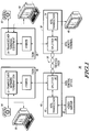
- FIG. 1 illustrates, in block diagram form, an asymmetric digital subscriber line (ADSL) system with accordance with the present invention.
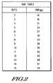
- FIG. 2 illustrates, in tabulator form, example reference signal-to-noise ratios in accordance with the present invention.
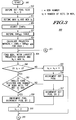
- FIG. 3 and FIG. 4 illustrate, in flow diagram form, a method for bit allocation in the system of FIG. 1 in accordance with the present invention.
- FIG. 5 illustrates, in flow diagram form, a method for bit allocation in the system of FIG. 1 in accordance with the present invention.
- FIG. 6 illustrates, in flow diagram form, a method for bit re-allocation in the system of FIG. 1 in accordance with the present invention.
- FIG. 7 illustrates, in flow diagram form, a method for fine gains adjustment in the system of FIG. 1 in accordance with the present invention.
- Generally, the present invention provides a method for allocating bits in the bins of an ADSL communications system, and equalizing the BER of the bins without substantially increasing aggregate transmit power. In particular, the bits are allocated by determining a projected margin. The projected margin is calculated for each bin by subtracting a reference SNR value from an estimated bin SNR. The reference SNR value is predetermined by theoretical calculation or by empirical data and stored in a look-up table. Bits are then allocated to the bin having the maximum projected margin. This provides the best BER without changing the transmit power.
- The BER is further improved by iteratively equalizing the individual bin BERs. This is accomplished by applying a fine gains adjustment to the transmit power. Specifically, the BER of the bins is equalized by calculating an adjustment gain and subtracting the adjustment gain from the bin currently having the maximum margin, and adding the same adjustment gain to the bin currently having the minimum margin. The iterations continue until all of the bin margins are within a predetermined threshold. This changes the individual bin transmit power levels without substantially changing the aggregate transmit power level. Also, the BER is substantially equalized, without causing the individual transmit power levels from exceeding a predetermined range, such as the range required by ANSI T1E1.4.
- FIG. 1 illustrates, in block diagram form, a
communication system 30 according to the present invention.Communication system 30 allows simultaneous transmission of ISDN and ADSL over the same telephone line, and includes ADSLcentral office 40, ADSLremote terminal 32, ISDNtransceiver 38, and ISDNtransceiver 46. ADSLremote terminal 32 includesADSL transceiver 34 andsplitter 36. Coupled to ADSLremote terminal 32 may be a communications device, such astelevision receiver 48.Twisted pair 18 couples the ADSLremote terminal 32 to the ADSLcentral office 40. Coupled to ADSLcentral office 40 may be a communications device, such asvideo server 58. - ADSL
central office 40 includesADSL transceiver 42 andsplitter 44.Splitter 44couples ADSL transceiver 42 to twistedpair 18, and splits received ISDN and ADSL signals to the appropriate corresponding receiver. Likewise, splitter 44 couples transmitted signals from both the ISDN transmitter and the ADSL transmitter to twistedpair 18.Splitter 44 includes band pass filter circuits for isolating the received ADSL signals from the ISDN signals, and circuits for combining the ADSL signals with the ISDN signals for transmission over the twisted pair. Splitter 36 functions in the same manner assplitter 44, and splits or combines ADSL and ISDN signals as necessary. - Communications devices, such as
telephone 52 orcomputer terminal 50 may be coupled to ISDNtransceiver 38. Likewise, coupled toISDN transceiver 46 may becomputer terminal 56 and/ortelephone 54. In operation,communication system 30 allows simultaneous transmission and reception of ISDN and ADSL signals ontwisted pair 18.ADSL transceiver 34 transmits an upstream ADSL signal acrosstwisted pair 18 to ADSLcentral office 40.ADSL transceiver 42 receives the upstream data signal fromADSL transceiver 34.ADSL transceiver 34 shifts or modifies the upstream ADSL signal up to a higher frequency band than that used by an ISDN network. The modified upstream ADSL signal can be transmitted along twistedpair 18 simultaneously with the ISDN signal. An ADSL receiver ofADSL transceiver 42 of thecentral office 40 band pass filters the ISDN signal and returns the modified upstream ADSL signal back to its original spectral band where it is converted to digital output data for use by a DSP. The downstream ADSL from ADSLcentral office 40 is modified so that it does not use the frequency band occupied by the ISDN signal. This modification is accomplished by changing the cut off frequency of the high pass filter of the downstream transmitter ofADSL transceiver 42 and of the high pass filter of the downstream receiver ofADSL transceiver 34. - FIG. 2 illustrates a signal-to-noise ratio (SNR) table in accordance with the present invention. The BITS column represents the number of bits that are allocated to a bin. In the embodiment illustrated in FIG. 2, only 2 bits through 15 bits can be allocated to a bin. The SNRREF column contains the signal-to-noise reference value, which represents a predetermined signal-to-noise value associated with each number of bits. The SNRREF values of FIG. 2 are used later in the discussion of FIGs. 3 - 7.
- FIG. 3 and FIG. 4 represent, in flow diagram form, a
method 300. Themethod 300 comprises oval transition blocks 301 through 303, rectangular step blocks 310 through 327, diamond shaped decision blocks 350 through 353, and circular change of flow blocks 370 through 373. In addition, the reference "i" refers to one of a plurality of bins, while the nomenclature "bi" references the number of bits allocated to a specific bin i. - In accordance with one embodiment of the invention, the
method 300 begins atstep 301. Next, atstep 310, a bit pool size is defined, and all bi values are set equal to 0. The bit pool size initially contains the number of data bits which need to be sent in a given ADSL frame, and represents the number of bits that need to be allocated to the plurality of bins. The bit pool value will change, as themethod 300 progresses. Setting all bi values equal to 0 indicates that no bits have been allocated to any bin, and that a new frame is being constructed. Next, at step 311 a maximum and minimum number of bits which can be transmitted from any bin in a given frame is defined. For example, it may be desirable to limit the number of bits a given bin can send to eight. Likewise, it may be desirable to limit the minimum number of bits which a bin can send. For example, the ADSL standard does not allow a bin to send only one bit, nor more than 15. - Next at
step 326 the initial SNR's, (ISNR) for the bins which were previously calculated during initialization are adjusted. If a bin is not to be used, the ISNR for that bin can be set to zero. If a bin is to be used, but not to its full capacity, the ISNR should be limited to a predetermined value. This allows the system to prohibit or limit transmissions at frequencies that may be simultaneously used by some other system. - At
step 327 the SNRREF table is defined. The SNRREF for a given number of bits is the required SNR value which achieves a desired bit error rate, where the bit error rate is a measure of system performance. Initially, there is a base table that is specific to a selected BER, such as described in FIGURE 2. In a system such as ADSL, error correction coding can be used to increase system performance. The increase in performance can be characterized by a coding gain. If error correction coding is used, a coding gain table can be subtracted from the base table, generating the SNRREF table to be used during allocation. Raising the values of the table allows for an allocation with extra margin to counteract transmission channel degradation. - Next, at a
step 312, a projected SNR margin is calculated. In one embodiment of the invention the projected SNR margin is calculated by taking the initial SNR for each bin and subtracting off the signal-to-noise reference value, SNRREF for a projected number of bits. - If a bin already has N bits allocated, and the projected number of bits is N+P, the SNRREF value to be used is the one for N+P bits. In this embodiment, the minimum number of bits that a bin can contain is 2. Therefore, before any bits are allocated, the projected margin is based on having 2 bits allocated. The projected margin would be a bin's initial SNR, (ISNR) minus the SNRREF value for 2 bits. If using the table in FIGURE 2, the resulting projected margin would be ISNR - 14. If a bin currently has a total of 6 bits allocated to it, the next projected number of allocated bits would be 7 bits, for a projection increase of 1. Therefore, a bin having 6 bits currently allocated would have a projected signal-to-noise margin of ISNRi - 30. The initial SNR for each individual bin is assumed to have been previously determined. Next, at
step 314, the bin with the largest projected signal-to-noise margin that contains fewer than the maximum number of bits allowed is identified. This is the best bin in this embodiment. - Choosing the bin with the largest projected margin allows for optimal bit error rate and system performance. For example, if a first bin had a projected margin of 30, a second bin had a projected signal-to-noise margin of 5, the first bin would be chosen because its projected signal-to-noise margin value, after it is allocated more data, will allow for the lowest overall system bit error rate. If a given bin has 15 bits allocated, where 15 is the maximum number of bits allowed, no more bits can be allocated, and that bin will not be chosen regardless of its projected margin. As discussed above, it is understood that a maximum value besides 15 could be chosen, and that other criteria could be input by the user to limit selection of a bin.
- Next, at
step 350, a determination is made whether the number of bits allocated to the selected bin is equal to 0. If the number of allocated bits is not equal to 0, indicating that bits are already allocated to the bin, themethod 300 proceeds to step 315. If this is the first time bits have been allocated to this bin,method 300 proceeds to step 351. Atstep 351, a determination is made whether some allocation dependent overhead bits are required, such as required by a trellis encoder. If no overhead bits are needed, flow proceeds to step 317. In the event overhead bits are required, flow proceeds to step 318. - At
step 318, the bit pool is decremented. This decrementing of the bit pool represents the fact that the bit pool is effectively decremented by two because two bits have been allocated to this bin, and the bit pool was also incremented by one to indicate an overhead bit added which is required by the trellis encoder. It is understood that different values may be added to the bit pool. The combination of the decrementing by two and incrementing by one givesstep 318 which is a single decrement to the bit pool for this embodiment. Atstep 317, the bit pool is decremented by two, which reflects that the fact that a total of two bits have been allocated to the selected bin. Flow fromsteps step 319. - At
step 319, the bits are allocated by setting the number of bits allocated to the bin equal to 2. Next, at change offlow step 370, a flow is indicated to change to the top of thesecond portion flow 300 on FIG. 4. Next, at change of direction flow A 372, flow continues atstep 320. - At
step 320, the projected margin is recalculated for the selected bin. For example, if the best bin received data for the flat time and now contains two allocated bits, the new projected margin would be the initial SNR of the selected bin less the SNRREF for its next possible allocation value of bits, in this case 3 bits, as determined from the table of FIG. 2. Next, atstep 352, a determination is made whether or not the bit pool is greater than 0. In the event that the bit pool is greater than 0 flow continues atstep 325. - At
step 325, any needed adjustments are made pertaining to changes in desired data rate, additional overhead bits, or changes in allocation criterion. - Flow continues at step 314 (FIG. 3) where a portion of the
method 300 will be repeated until the bit pool is less than or equal to 0. In another embodiment, thestep 325 could be performed only initially followingstep 311. If the bit pool is not greater than 0, flow continues atstep 353. - At step 353 a determination is made whether or not the bit pool is equal to 0. If the bit pool is equal to 0, flow proceeds to step 302 and the
method 300 ends. In the event the bit pool is not equal to 0, (i.e., the bit pool is less than 0), flow continues atstep 321. For example, if upon returning to step 314 there were a single bit remaining to be allocated, and a bin were chosen which had no previously allocated bits, that bin would have to be allocated a total of two bits, even though only one bit remains Therefore, it is possible to have a bit pool value of less than 0. Atstep 321, the current margin for all bins is calculated. The current margin for each bin, as opposed to the projected margin, is the initial signal-to-noise less the signal-to-noise reference for the bits allocated to each bin from the table of FIG. 2. Next atstep 322 the bin with the smallest current margin is selected that also has more than two bits allocated to it. Next atstep 323, one bit is de-allocated from this bin. For example, if a bin has four bits allocated to it and has the smallest current margin its number of allocated bits would be reduced from four to three. Next at astep 324, any final adjustments are made. One situation where a final adjustment would need to be made would be in the event a bit needs to be de-allocated, but all the bins contain exactly two bits. In this situation, no single bit can be de-allocated from any bin. Therefore, it would be necessary to combine two bins together so that it had a total allocated bit number of 4 from which a single bit could be de-allocated. Other type of anomalies may occur and would be taken care of instep 324. Next atstep 303 themethod 300 ends. - FIG. 5 represents, in flow diagram form, a
method 500. Themethod 500 comprises oval transition blocks 501 and 502, and rectangular step blocks 510 through 512. - In FIG. 5,
flow 500 provides a modification to theflow 300 in accordance with the present invention. Atstep 501 theflow 500 starts. Next, atstep 510, the bin with the next largest projected margin is determined. This is the next best bin. Next, atstep 511, the amount of data that the best bin can be allocated is determined. The best bin will be allocated enough data so that it will have a new projected margin worse than that of the next best bin. This can be determined by subtracting the projected margin of the next best bin from the projected margin of the best bin to get a projected margin difference. Based on the projected margin difference, the number of bits that can be allocated to the best bin can be determined by the table in FIG. 2. For example, assuming the best bin and next best bin are empty, if the best bin has a projected margin of 40, and the next best bin has a projected margin of 15, the projected difference is 25. Referring to the table in FIG. 2, six bits would be chosen to be allocated to the best bin. Six bits are chosen because that is the smallest number of bits with a signal-to-noise reference greater than or equal to the projected difference. If the best bin has bits already allocated, the six bits would represent the total number of bits that the bin should have allocated. Theflow 500 could be inserted betweensteps - FIG. 6 represents, in flow diagram form, a
method 600. Themethod 600 comprises oval transition blocks 601 and 602, rectangular step blocks 610 through 617, and diamond shapeddecision block 650. This flow describes the method of determining if an allocation adaptation is necessary, and if so, what adaptation should occur. - At
step 601 theflow 600 starts, and assumes a frame with bits already allocated has been identified. Next, atstep 610, a threshold is defined. The threshold is used to determine if an adaptation should occur. Next, atstep 617, the projected signal-to-noise margin is calculated in a similar manner to that of step 312 (FIG. 3). Next, atstep 611, the current signal-to-noise margin is calculated in a similar manner to step 321 (FIG. 3). Next, atstep 612, the N best bins are selected. N is an integer value and is user defined. In one embodiment of the present invention, the N best bins are those bins having the largest projected signal-to-noise margin. Next, atstep 613, the M worst bins are selected. M is an integer value and is user defined. The M worst bins are those bins having the smallest current signal-to-noise margin. Next, atstep 614, the signal-to-noise difference between the best of the N best bins and the worst of the M worst bins is calculated. Next, atstep 650, a determination is made whether the signal-to-noise difference is greater than the margin threshold. If yes, flow proceeds to step 615; if no, flow ends by proceeding to step 602. Atstep 615, data is swapped from the M worst bins to the N best bins making sure not to violate a minimum or maximum bit value. In one embodiment, a single bit would be swapped. Next, atstep 616, the projected and current SNRs are recalculated. A portion of theflow 600 repeats by returning to step 612. - FIG. 7 illustrates, in flow diagram form, a
method 700 for providing fine gains adjustment in accordance with an embodiment of the present invention.Method 700 includes rectangular boxes having reference numbers 710 - 718 and 719 - 722 representing steps for performing the fine gains adjustment, and a diamond shaped box havingreference number 750 representing a decision step ofmethod 700. - At
step 710, a maximum gain is defined by a user ofcommunications system 30. The maximum gain is defined as a maximum amount that the gain of a bin can be adjusted. For example, ANSI T1E1.4 requires that the maximum gain not be greater than approximately 1.5 decibels (dB). Atstep 711, a margin is calculated for each bin that has at least one bit allocated to it. This margin is determined by subtracting the reference signal-to-noise ratio value (SNRREF) for each bin, as identified in the table of FIG. 2, from the initial signal-to-noise ratio (SNR) value for that bin. Atstep 712, the available bin with the largest margin is identified. A bin is available if the gain of the bin has been adjusted down by less than the maximum gain defined instep 710. Atstep 713, the available bin with the smallest margin is selected. As discussed above, a bin would be unavailable for selection if it had already been gained up by the maximum gain defined atstep 710. - At
step 714 an average of the maximum margin and the minimum margin is calculated. For example if the maximum margin is 8 dB and the minimum margin is 4 dB, the average would be 6 dB. Next, atstep 715, an intermediate gain is calculated. The intermediate gain is determined in the illustrated embodiment by subtracting the minimum margin from the average calculated instep 714. - At
step 716, a minimum tweak value is determined by subtracting the gain of the bin with the minimum margin from the maximum gain defined instep 710. The minimum tweak value is the amount in which the gain of the bin with the minimum margin can be adjusted up. Next, atstep 717, the maximum tweak value is defined as the maximum gain defined atstep 710, plus the gain of the bin having the maximum margin. The maximum tweak is the amount in which the gain of the bin with the maximum margin can be adjusted down. - Next, at
step 718, an adjustment gain (ADJ) is determined by taking the smallest of the intermediate gain calculated atstep 715, the minimum tweak determined atstep 716, or the maximum tweak fromstep 717. This assures that the gain of each of the bins is not adjusted beyond the maximum gain fromstep 710. Also, when gain is added to a bin, a corresponding amount of gain is subtracted from another bin, thus ensuring that the aggregate transmit power levels do not substantially change. - At
decision step 750, a determination is made whether or not the adjustment gain is below a predetermined threshold. The threshold is a predetermined value below which no further fine gains adjustments are needed. If the adjustment value is less than the threshold, the YES path is taken to ENDstep 702. If the adjustment value is not less than the threshold, the NO path is taken to step 719. In an ideal system, the threshold may be equal to zero. - At
step 719, the gain corresponding to the maximum margin is decreased by the adjustment value. Atstep 720, the gain corresponding to the minimum margin is increased by the adjustment value. Atstep 721, the maximum margin is decreased by the adjustment value. Atstep 722, the minimum margin is increased by the adjustment value. Fromstep 722, the flow diagram returns to step 712, and steps 712 - 722 are repeated until the adjustment gain is less than the threshold. Because the gain of one bin is not adjusted up without another the gain of another bin being adjusted down by a corresponding amount, an aggregate change in margin for all of the bins is substantially zero. - The previous methods may also be characterized by:
- defining an initial signal-to-noise value for each of the plurality of bins (326);
- defining a reference signal-to-noise value, wherein the reference signal-to-noise value is an amount of signal-to-noise needed to allocate a given amount of data at a given bit error rate (327);
- defining a pool having an at least one bit of unallocated data (310);
- calculating a projected signal-to-noise margin for each of the plurality of bins based on the initial signal-to-noise value and the reference signal-to-noise value (312);
- selecting a best bin from the plurality of bins based on the projected signal-to-noise margin, wherein the best bin has a largest projected signal-to-noise margin (314);
- allocating a portion of the pool to the best bin (315, 319);
- decrementing the pool based on the portion (316, 317); and
- repeating the steps of calculating, selecting, allocating, and decrementing until the pool has no more at least one bit of unallocated data.
- Another way of characterizing previous methods includes
- defining an initial signal-to-noise value for each of the plurality of bins (326);
- defining a reference signal-to-noise value (327);
- calculating a projected signal-to-noise margin for each of the plurality of bins based on the initial signal-to-noise value and the reference signal-to-noise value (312);
- selecting a best bin and a next best bin from the plurality of bins based on the projected signal-to-noise margin (510);
- determining a minimum amount of data to allocate to the best bin, wherein the minimum amount of data causes the best bin to have a new projected signal-to-noise margin worse than that of the next best bin (511); and
- allocating the minimum amount of data to the best bin (512).
- Yet another characterization of the previous method includes:
- defining a margin threshold (610);
- defining an initial signal-to-noise value for each of the plurality of bins;
- defining a reference signal-to-noise value for each possible amount of data;
- calculating a current signal-to-noise margin for an each of the plurality of bins based on the initial signal-to-noise value and the reference signal-to-noise value for each of the plurality of bins;
- calculating a projected signal-to-noise margin for each of the plurality of bins based on the initial signal-to-noise value and the reference signal-to-noise value (617);
- selecting N best bins from the plurality of bins based on the projected signal-to-noise margin, wherein the N best bins have a best bin having a best projected signal-to-noise margin (612);
- selecting M worst bins from the plurality of bins based on the current signal-to-noise margin, wherein the M worst bins have a worst bin having a worst current signal-to-noise margin (613);
- calculating a signal-to-noise difference based on the best bin and the worst bin (614);
- swapping a portion of data from the M worst bins to the N best bins if a threshold value is greater than the margin threshold, wherein the step of swapping creates modified bins;
- recalculating the projected signal-to-noise margin and the current signal-to-noise margin for the modified bins (615); and
- repeating the steps of selecting N, selecting M, calculating, swapping, and recalculating while the threshold value is greater than the margin threshold.
- While the invention has been described in the context of a preferred embodiment, it will be apparent to those skilled in the art that the present invention may be modified in numerous ways and may assume many embodiments other than that specifically set out and described above. For example, the present invention is implemented in software. However, in other embodiments, the invention may be implemented in hardware, software, or a combination of hardware and software. Accordingly, it is intended by the appended claims to cover all modifications of the invention which fall within the true spirit and scope of the invention.
Claims (10)
- A method of allocating data in a data communication system (30) having a plurality of bins for sending data, the data communication system comprising:defining an initial signal-to-noise value for each of the plurality of bins (326);defining a reference signal-to-noise value(327);calculating a projected signal-to-noise margin for each of the plurality of bins based on the initial signal-to-noise value and the reference signal-to-noise value (312);selecting a best bin from the plurality of bins based on the projected signal-to-noise margin (314); andallocating a portion of the data to the best bin (315, 319).
- The method of claim 1, wherein the step of calculating a projected signal-to-noise margin is determined by subtracting the reference signal-to-noise value from the initial signal-to-noise value (312).
- The method of claim 2, wherein the reference signal-to-noise value is an amount of signal-to-noise needed for an allocated amount of data at a given bit error rate.
- The method of claim 1 further comprising the steps of:recalculating the projected signal-to-noise margin for the best bin (320); andrepeating the steps of, selecting (314), allocating (315, 319), and recalculating (320).
- The method of claim 4, wherein:the data comprises a bit pool having at least one bit of data (310); andthe step of allocating bits includes allocating at least one bit of the bit pool to the best bin (315, 319).
- The method of claim 5, further comprising the step of:removing at least one bit from the bit pool (316, 317).
- The method of claim 6, further comprising the step of:removing at least one bit from the bit pool during a transmission.
- The method of claim 5, further comprising the step of:adding at least one bit to the bit pool.
- The method of claim 8, further comprising the step of:adding the at least one bit to the bit pool during a transmission.
- The method of claim 1, further comprising the step of:calculating new reference signal-to-noise values.
Applications Claiming Priority (2)
| Application Number | Priority Date | Filing Date | Title |
|---|---|---|---|
| US08/660,380 US5852633A (en) | 1996-06-07 | 1996-06-07 | Method for allocating data in a data communication system |
| US660380 | 1996-06-07 |
Publications (2)
| Publication Number | Publication Date |
|---|---|
| EP0812087A2 true EP0812087A2 (en) | 1997-12-10 |
| EP0812087A3 EP0812087A3 (en) | 1999-10-20 |
Family
ID=24649309
Family Applications (1)
| Application Number | Title | Priority Date | Filing Date |
|---|---|---|---|
| EP97108579A Withdrawn EP0812087A3 (en) | 1996-06-07 | 1997-05-28 | Method for allocating data in a data communication system |
Country Status (3)
| Country | Link |
|---|---|
| US (1) | US5852633A (en) |
| EP (1) | EP0812087A3 (en) |
| JP (1) | JP4315478B2 (en) |
Cited By (24)
| Publication number | Priority date | Publication date | Assignee | Title |
|---|---|---|---|---|
| WO1998057472A1 (en) * | 1997-06-12 | 1998-12-17 | Aware, Inc. | Adaptive bit allocation for variable bandwidth multicarrier communication |
| WO1999020027A2 (en) * | 1997-10-10 | 1999-04-22 | Aware, Inc. | Splitterless multicarrier modem |
| EP0918422A2 (en) * | 1997-11-24 | 1999-05-26 | Motorola, Inc. | Method for reallocating data in a discrete multi-tone communication system |
| WO1999053679A1 (en) * | 1998-04-08 | 1999-10-21 | Fujitsu Limited | Transmission method for subscriber line |
| WO1999056452A1 (en) * | 1998-04-24 | 1999-11-04 | Mitsubishi Denki Kabushiki Kaisha | Data communication apparatus |
| WO1999057877A1 (en) * | 1998-05-06 | 1999-11-11 | Mitsubishi Denki Kabushiki Kaisha | System and method for discrete multitone communication |
| WO2000031940A1 (en) * | 1998-11-25 | 2000-06-02 | Aware, Inc. | Bit allocation among carriers in multicarrier communications |
| WO2000039977A1 (en) * | 1998-12-23 | 2000-07-06 | Broadcom Corporation | Method for optimisation of dsl communications |
| WO2000051303A1 (en) * | 1999-02-23 | 2000-08-31 | Aware, Inc. | Apparatus and method of tone allocation in digital subscriber line systems |
| US6266348B1 (en) | 1997-10-10 | 2001-07-24 | Aware, Inc. | Splitterless multicarrier modem |
| WO2002076074A2 (en) * | 2001-03-16 | 2002-09-26 | Siemens Aktiengesellschaft | Method for improving transmission quality between telecommunication devices |
| US6498808B1 (en) | 1999-03-12 | 2002-12-24 | Aware, Inc. | Seamless rate adaptive multicarrier modulation system and protocols |
| US6522666B1 (en) | 1998-06-26 | 2003-02-18 | Aware, Inc. | Multicarrier communication with variable overhead rate |
| US6748016B1 (en) | 1999-07-16 | 2004-06-08 | Aware, Inc. | System and method for transmitting messages between transceivers using electromagnetically coupled signals |
| US6775320B1 (en) | 1999-03-12 | 2004-08-10 | Aware, Inc. | Method and a multi-carrier transceiver supporting dynamic switching between active application sets |
| US6778595B1 (en) | 1999-10-29 | 2004-08-17 | Fujitsu Limited | ADSL modem |
| EP1453267A2 (en) * | 1998-11-25 | 2004-09-01 | Aware, Inc. | Bit allocation among carriers in multicarrier communications |
| US6798735B1 (en) | 1996-06-12 | 2004-09-28 | Aware, Inc. | Adaptive allocation for variable bandwidth multicarrier communication |
| US6870888B1 (en) | 1998-11-25 | 2005-03-22 | Aware, Inc. | Bit allocation among carriers in multicarrier communications |
| US6980601B2 (en) | 2000-11-17 | 2005-12-27 | Broadcom Corporation | Rate adaptation and parameter optimization for multi-band single carrier transmission |
| US7860175B2 (en) | 1999-03-12 | 2010-12-28 | Tzannes Marcos C | Method for seamlessly changing power modes in an ADSL system |
| EP2267963A3 (en) * | 2000-04-18 | 2011-03-09 | Aware, Inc. | Multicarrier system with a plurality of SNR margins |
| US8031619B2 (en) | 1997-10-10 | 2011-10-04 | Daphimo Co., B.V., LLC | Splitterless multicarrier modem |
| EP2784969A1 (en) * | 2013-03-28 | 2014-10-01 | British Telecommunications public limited company | Communications network |
Families Citing this family (37)
| Publication number | Priority date | Publication date | Assignee | Title |
|---|---|---|---|---|
| US5852655A (en) | 1996-03-29 | 1998-12-22 | Cisco Systems, Inc. | Communication server apparatus having distributed switching and method |
| US6385203B2 (en) * | 1996-03-29 | 2002-05-07 | Cisco Technology, Inc. | Communication server apparatus and method |
| US6160843A (en) * | 1996-03-29 | 2000-12-12 | Cisco Technology, Inc. | Communication server apparatus providing XDSL services and method |
| US6044107A (en) * | 1996-05-09 | 2000-03-28 | Texas Instruments Incorporated | Method for interoperability of a T1E1.4 compliant ADSL modem and a simpler modem |
| US6163599A (en) | 1997-03-20 | 2000-12-19 | Cisco Technology, Inc. | Communication server apparatus and method |
| US6647058B1 (en) * | 1997-06-23 | 2003-11-11 | Paradyne Corporation | Performance customization system and process for optimizing XDSL performance |
| US6005893A (en) * | 1997-09-23 | 1999-12-21 | Telefonaktiebolaget Lm Ericsson | Reduced complexity bit allocation to subchannels in a multi-carrier, high speed data transmission system |
| US6130882A (en) * | 1997-09-25 | 2000-10-10 | Motorola, Inc. | Method and apparatus for configuring a communication system |
| US6459678B1 (en) | 1997-12-05 | 2002-10-01 | Globespan Semiconductor, Inc. | System and method for providing near optimal bit loading in a discrete multi-tone modulation system |
| US6128348A (en) * | 1997-12-16 | 2000-10-03 | Integrated Telecom Express | Method for configuring data and energy parameters in a multi-channel communications system |
| US6094459A (en) * | 1997-12-16 | 2000-07-25 | Integrated Telecom Express | Circuit for configuring data and energy parameters in a multi-channel communications system |
| US6075821A (en) * | 1997-12-16 | 2000-06-13 | Integrated Telecom Express | Method of configuring and dynamically adapting data and energy parameters in a multi-channel communications system |
| US6084917A (en) | 1997-12-16 | 2000-07-04 | Integrated Telecom Express | Circuit for configuring and dynamically adapting data and energy parameters in a multi-channel communications system |
| US6084906A (en) * | 1997-12-17 | 2000-07-04 | Integrated Telecom Express | ADSL transceiver implemented with associated bit and energy loading integrated circuit |
| US7512149B2 (en) * | 2003-04-23 | 2009-03-31 | At & T Intellectual Property Ii, L.P. | Bit and power allocation scheme for full-duplex transmission with echo cancellation in multicarrier-based modems |
| JP3191802B2 (en) * | 1999-06-17 | 2001-07-23 | 三菱電機株式会社 | Communication device and communication method |
| EP1079578A3 (en) * | 1999-08-23 | 2001-11-07 | Motorola, Inc. | Data allocation in multicarrier systems |
| US6625777B1 (en) | 1999-10-19 | 2003-09-23 | Motorola, Inc. | Method of identifying an improved configuration for a communication system using coding gain and an apparatus therefor |
| US8363744B2 (en) | 2001-06-10 | 2013-01-29 | Aloft Media, Llc | Method and system for robust, secure, and high-efficiency voice and packet transmission over ad-hoc, mesh, and MIMO communication networks |
| US7103096B2 (en) | 2000-10-12 | 2006-09-05 | 3Com Corporation | Performance evaluation of multicarrier channels with forward error correction and automatic retransmission request |
| US7110467B2 (en) * | 2000-10-12 | 2006-09-19 | 3Com Corporation | Performance evaluation of a G.dmt-compliant digital subscriber line system |
| US6732323B1 (en) | 2000-10-12 | 2004-05-04 | 3Com Corporation | Method of selecting initialization parameters for multi-channel data communication with forward error correction |
| US7131038B2 (en) * | 2000-10-12 | 2006-10-31 | 3Com Corporation | Performance evaluation of multicarrier channels |
| US6973122B1 (en) * | 2001-01-26 | 2005-12-06 | At&T Corp. | Power allocation scheme for DMT-based modems employing simplex transmission |
| US7133419B1 (en) * | 2001-05-04 | 2006-11-07 | Conexant, Inc. | System and method for reducing power consumption by spectral shaping of signals |
| AU2002308688A1 (en) * | 2001-05-10 | 2002-11-18 | Verma Amit | Fast exchange during initialization in multicarrier communication systems |
| US6718493B1 (en) | 2001-05-17 | 2004-04-06 | 3Com Corporation | Method and apparatus for selection of ARQ parameters and estimation of improved communications |
| US7263130B1 (en) | 2001-05-25 | 2007-08-28 | 3Com Corporation | Method and apparatus for evaluating error control parameters of self-similar constellations |
| JP3607643B2 (en) * | 2001-07-13 | 2005-01-05 | 松下電器産業株式会社 | Multicarrier transmission apparatus, multicarrier reception apparatus, and multicarrier radio communication method |
| US20030097623A1 (en) * | 2001-10-24 | 2003-05-22 | Javad Razavilar | Method and apparatus for performance optimization and adaptive bit loading for wireless modems with convolutional coder, FEC, CRC and ARQ |
| KR100456693B1 (en) * | 2002-03-28 | 2004-11-10 | 삼성전자주식회사 | Method for minimizing setupt time by the optimization of bit allocation on multi-canannel communication system |
| US7151803B1 (en) | 2002-04-01 | 2006-12-19 | At&T Corp. | Multiuser allocation method for maximizing transmission capacity |
| US7145956B2 (en) * | 2002-06-27 | 2006-12-05 | Smart Link Ltd. | Method for achieving a target bit rate in a multi-carrier data communication system |
| JP4732193B2 (en) * | 2006-03-01 | 2011-07-27 | 住友電工ネットワークス株式会社 | COMMUNICATION DEVICE, COMMUNICATION SYSTEM, AND COMMUNICATION METHOD |
| US8611439B2 (en) * | 2007-06-28 | 2013-12-17 | Edgewater Computer Systems, Inc. | System and method to optimize multicarrier communication |
| US8705598B2 (en) * | 2011-12-15 | 2014-04-22 | Tektronix, Inc. | Signal-sensitive data compression |
| CN108111249B (en) * | 2016-11-24 | 2021-03-30 | 富士通株式会社 | Method and device for bit number distribution and power distribution of subcarriers and electronic equipment |
Citations (3)
| Publication number | Priority date | Publication date | Assignee | Title |
|---|---|---|---|---|
| US4679227A (en) * | 1985-05-20 | 1987-07-07 | Telebit Corporation | Ensemble modem structure for imperfect transmission media |
| WO1995028773A1 (en) * | 1994-04-14 | 1995-10-26 | Amati Communications Corporation | Improved adsl compatible discrete multi-tone apparatus |
| US5479447A (en) * | 1993-05-03 | 1995-12-26 | The Board Of Trustees Of The Leland Stanford, Junior University | Method and apparatus for adaptive, variable bandwidth, high-speed data transmission of a multicarrier signal over digital subscriber lines |
Family Cites Families (9)
| Publication number | Priority date | Publication date | Assignee | Title |
|---|---|---|---|---|
| US4328581A (en) * | 1980-06-20 | 1982-05-04 | Rockwell International Corporation | Adaptive HF communication system |
| US4833706A (en) * | 1985-05-20 | 1989-05-23 | Telebit Corporation | Ensemble modem structure for imperfect transmission media |
| US5548819A (en) * | 1991-12-02 | 1996-08-20 | Spectraplex, Inc. | Method and apparatus for communication of information |
| US5309503A (en) * | 1991-12-06 | 1994-05-03 | Motorola, Inc. | Dynamic channel assignment in a communication system |
| JP2518156B2 (en) * | 1993-07-19 | 1996-07-24 | 日本電気株式会社 | Channel allocation method for wireless communication system |
| US5596604A (en) * | 1993-08-17 | 1997-01-21 | Amati Communications Corporation | Multicarrier modulation transmission system with variable delay |
| US5400322A (en) * | 1993-08-20 | 1995-03-21 | Amati Communications Corp. | Updating of bit allocations in a multicarrier modulation transmission system |
| US5598435A (en) * | 1993-12-23 | 1997-01-28 | British Telecommunications Public Limited Company | Digital modulation using QAM with multiple signal point constellations not equal to a power of two |
| JP2661533B2 (en) * | 1993-12-27 | 1997-10-08 | 日本電気株式会社 | Channel allocation method for mobile communication system |
-
1996
- 1996-06-07 US US08/660,380 patent/US5852633A/en not_active Expired - Lifetime
-
1997
- 1997-05-28 EP EP97108579A patent/EP0812087A3/en not_active Withdrawn
- 1997-06-02 JP JP15921597A patent/JP4315478B2/en not_active Expired - Lifetime
Patent Citations (3)
| Publication number | Priority date | Publication date | Assignee | Title |
|---|---|---|---|---|
| US4679227A (en) * | 1985-05-20 | 1987-07-07 | Telebit Corporation | Ensemble modem structure for imperfect transmission media |
| US5479447A (en) * | 1993-05-03 | 1995-12-26 | The Board Of Trustees Of The Leland Stanford, Junior University | Method and apparatus for adaptive, variable bandwidth, high-speed data transmission of a multicarrier signal over digital subscriber lines |
| WO1995028773A1 (en) * | 1994-04-14 | 1995-10-26 | Amati Communications Corporation | Improved adsl compatible discrete multi-tone apparatus |
Non-Patent Citations (1)
| Title |
|---|
| BINGHAM J A C: "MULTICARRIER MODULATION FOR DATA TRANSMISSION: AN IDEA WHOSE TIME HAS COME" IEEE COMMUNICATIONS MAGAZINE, vol. 28, no. 5, 1 May 1990 (1990-05-01), pages 5-8, 11 - 14, XP000132491 New York, USA ISSN: 0163-6804 * |
Cited By (66)
| Publication number | Priority date | Publication date | Assignee | Title |
|---|---|---|---|---|
| US6798735B1 (en) | 1996-06-12 | 2004-09-28 | Aware, Inc. | Adaptive allocation for variable bandwidth multicarrier communication |
| US8369275B2 (en) | 1996-06-12 | 2013-02-05 | Daphimo Co. B.V., Llc | Adaptive allocation for variable bandwidth multicarrier communication |
| US8767698B2 (en) | 1996-06-12 | 2014-07-01 | Intellectual Ventures Ii Llc | Adaptive allocation for variable bandwidth multicarrier communication |
| US7817532B2 (en) | 1996-06-12 | 2010-10-19 | Marcos Tzannes | Adaptive allocation for variable bandwidth multicarrier communication |
| WO1998057472A1 (en) * | 1997-06-12 | 1998-12-17 | Aware, Inc. | Adaptive bit allocation for variable bandwidth multicarrier communication |
| US6266348B1 (en) | 1997-10-10 | 2001-07-24 | Aware, Inc. | Splitterless multicarrier modem |
| WO1999020027A3 (en) * | 1997-10-10 | 1999-08-05 | Aware Inc | Splitterless multicarrier modem |
| AU763810B2 (en) * | 1997-10-10 | 2003-07-31 | Daphimo Co. B.V., Llc | Splitterless multicarrier modem |
| US8717928B2 (en) | 1997-10-10 | 2014-05-06 | Intellectual Ventures Ii Llc | Splitterless multicarrier modem |
| WO1999020027A2 (en) * | 1997-10-10 | 1999-04-22 | Aware, Inc. | Splitterless multicarrier modem |
| US8031619B2 (en) | 1997-10-10 | 2011-10-04 | Daphimo Co., B.V., LLC | Splitterless multicarrier modem |
| US8400940B2 (en) | 1997-10-10 | 2013-03-19 | Daphimo Co., B.V., LLC | Splitterless multicarrier modem |
| US6549520B1 (en) | 1997-10-10 | 2003-04-15 | Aware, Inc. | Method and apparatus for varying power levels in a multicarrier modem |
| AU763810C (en) * | 1997-10-10 | 2004-07-15 | Daphimo Co. B.V., Llc | Splitterless multicarrier modem |
| AU744756B2 (en) * | 1997-10-10 | 2002-03-07 | Daphimo Co. B.V., Llc | Splitterless multicarrier modem |
| US6122247A (en) * | 1997-11-24 | 2000-09-19 | Motorola Inc. | Method for reallocating data in a discrete multi-tone communication system |
| EP0918422A2 (en) * | 1997-11-24 | 1999-05-26 | Motorola, Inc. | Method for reallocating data in a discrete multi-tone communication system |
| EP0918422A3 (en) * | 1997-11-24 | 1999-10-20 | Motorola, Inc. | Method for reallocating data in a discrete multi-tone communication system |
| WO1999053679A1 (en) * | 1998-04-08 | 1999-10-21 | Fujitsu Limited | Transmission method for subscriber line |
| WO1999056452A1 (en) * | 1998-04-24 | 1999-11-04 | Mitsubishi Denki Kabushiki Kaisha | Data communication apparatus |
| US6522731B2 (en) | 1998-04-24 | 2003-02-18 | Mitsubishi Denki Kabushiki Kaisha | Data communication apparatus |
| WO1999057877A1 (en) * | 1998-05-06 | 1999-11-11 | Mitsubishi Denki Kabushiki Kaisha | System and method for discrete multitone communication |
| US6522666B1 (en) | 1998-06-26 | 2003-02-18 | Aware, Inc. | Multicarrier communication with variable overhead rate |
| US8718179B2 (en) | 1998-06-26 | 2014-05-06 | Intellectual Ventures Ii Llc | Multicarrier communication with variable overhead rate |
| WO2000031940A1 (en) * | 1998-11-25 | 2000-06-02 | Aware, Inc. | Bit allocation among carriers in multicarrier communications |
| AU754597B2 (en) * | 1998-11-25 | 2002-11-21 | Tq Delta, Llc | Bit allocation among carriers in multicarrier communications |
| US8218664B2 (en) | 1998-11-25 | 2012-07-10 | Daphimo Co. B.V., Llc | Bit allocation among carriers in multicarrier communications |
| EP1453267A2 (en) * | 1998-11-25 | 2004-09-01 | Aware, Inc. | Bit allocation among carriers in multicarrier communications |
| US6870888B1 (en) | 1998-11-25 | 2005-03-22 | Aware, Inc. | Bit allocation among carriers in multicarrier communications |
| US7801225B2 (en) | 1998-11-25 | 2010-09-21 | Shapiro Jerome M | Bit allocation among carriers in multicarrier communications |
| US6310909B1 (en) | 1998-12-23 | 2001-10-30 | Broadcom Corporation | DSL rate adaptation |
| WO2000039977A1 (en) * | 1998-12-23 | 2000-07-06 | Broadcom Corporation | Method for optimisation of dsl communications |
| US7609757B2 (en) | 1998-12-23 | 2009-10-27 | Broadcom Corporation | DSL rate adaptation |
| US6904082B2 (en) | 1998-12-23 | 2005-06-07 | Broadcom Corporation | DSL rate adaptation |
| WO2000051303A1 (en) * | 1999-02-23 | 2000-08-31 | Aware, Inc. | Apparatus and method of tone allocation in digital subscriber line systems |
| US6498808B1 (en) | 1999-03-12 | 2002-12-24 | Aware, Inc. | Seamless rate adaptive multicarrier modulation system and protocols |
| US8340200B2 (en) | 1999-03-12 | 2012-12-25 | Daphimo Co. B.V., Llc | Method for seamlessly changing power modes in an ADSL system |
| US7649928B2 (en) | 1999-03-12 | 2010-01-19 | Tzannes Marcos C | Method for synchronizing seamless rate adaptation |
| US9369404B2 (en) | 1999-03-12 | 2016-06-14 | Intellectual Ventures Ii Llc | Method and multi-carrier transceiver with stored application profiles for supporting multiple applications |
| US7813419B2 (en) | 1999-03-12 | 2010-10-12 | Tzannes Marcos C | Method and multi-carrier transceiver with stored application profiles for supporting multiple applications |
| US7813418B2 (en) | 1999-03-12 | 2010-10-12 | Tzannes Marcos C | Method and a multi-carrier transceiver supporting dynamic switching between active application sets |
| US6778596B1 (en) | 1999-03-12 | 2004-08-17 | Aware, Inc. | Method and multi-carrier transceiver with stored application profiles for supporting multiple applications |
| US7860175B2 (en) | 1999-03-12 | 2010-12-28 | Tzannes Marcos C | Method for seamlessly changing power modes in an ADSL system |
| US8934555B2 (en) | 1999-03-12 | 2015-01-13 | Intellectual Ventures Ii Llc | Method and multi-carrier transceiver with stored application profiles for supporting multiple applications |
| US6667991B1 (en) | 1999-03-12 | 2003-12-23 | Aware, Inc. | Method for synchronizing seamless rate adaptation |
| US8045603B2 (en) | 1999-03-12 | 2011-10-25 | Daphimo Co. B.V., Llc | Method and a multi-carrier transceiver supporting dynamic switching between active application sets |
| US8045601B2 (en) | 1999-03-12 | 2011-10-25 | Daphimo Co. B.V., Llc | Method for synchronizing seamless rate adaptation |
| US6775320B1 (en) | 1999-03-12 | 2004-08-10 | Aware, Inc. | Method and a multi-carrier transceiver supporting dynamic switching between active application sets |
| US8718163B2 (en) | 1999-03-12 | 2014-05-06 | Intellectual Ventures Ii Llc | Method for seamlessly changing power modes in an ADSL system |
| US8340162B2 (en) | 1999-03-12 | 2012-12-25 | Daphimo Co. B.V., Llc | Method for synchronizing seamless rate adaptation |
| US8351491B2 (en) | 1999-03-12 | 2013-01-08 | Daphimo Co. B.V., Llc | Method and multi-carrier transceiver with stored application profiles for supporting multiple applications |
| US6567473B1 (en) | 1999-03-12 | 2003-05-20 | Aware, Inc. | Method for seamlessly changing power modes in a ADSL system |
| US6748016B1 (en) | 1999-07-16 | 2004-06-08 | Aware, Inc. | System and method for transmitting messages between transceivers using electromagnetically coupled signals |
| US6778595B1 (en) | 1999-10-29 | 2004-08-17 | Fujitsu Limited | ADSL modem |
| EP2267963A3 (en) * | 2000-04-18 | 2011-03-09 | Aware, Inc. | Multicarrier system with a plurality of SNR margins |
| US8625660B2 (en) | 2000-04-18 | 2014-01-07 | Tq Delta, Llc | Systems and methods for a multicarrier modulation system with a variable margin |
| US8374226B2 (en) | 2000-04-18 | 2013-02-12 | Tq Delta, Llc | Systems and methods for a multicarrier modulation system with a variable margin |
| US8937988B2 (en) | 2000-04-18 | 2015-01-20 | Tq Delta, Llc | Systems and methods for a multicarrier modulation system with a variable margin |
| US9154354B2 (en) | 2000-04-18 | 2015-10-06 | Tq Delta, Llc | Systems and methods for a multicarrier modulation system with a variable margin |
| US9893921B2 (en) | 2000-04-18 | 2018-02-13 | Tq Delta, Llc | Systems and methods for a multicarrier modulation system with a variable margin |
| US10708104B2 (en) | 2000-04-18 | 2020-07-07 | Tq Delta, Llc | Systems and methods for a multicarrier modulation system with a variable margin |
| US7512186B2 (en) | 2000-11-17 | 2009-03-31 | Broadcom Corporation | Rate adaptation and parameter optimization for multi-band single carrier transmission |
| US6980601B2 (en) | 2000-11-17 | 2005-12-27 | Broadcom Corporation | Rate adaptation and parameter optimization for multi-band single carrier transmission |
| WO2002076074A3 (en) * | 2001-03-16 | 2003-05-08 | Siemens Ag | Method for improving transmission quality between telecommunication devices |
| WO2002076074A2 (en) * | 2001-03-16 | 2002-09-26 | Siemens Aktiengesellschaft | Method for improving transmission quality between telecommunication devices |
| EP2784969A1 (en) * | 2013-03-28 | 2014-10-01 | British Telecommunications public limited company | Communications network |
Also Published As
| Publication number | Publication date |
|---|---|
| EP0812087A3 (en) | 1999-10-20 |
| US5852633A (en) | 1998-12-22 |
| JP4315478B2 (en) | 2009-08-19 |
| JPH10155031A (en) | 1998-06-09 |
Similar Documents
| Publication | Publication Date | Title |
|---|---|---|
| US5822374A (en) | Method for fine gains adjustment in an ADSL communications system | |
| US5852633A (en) | Method for allocating data in a data communication system | |
| KR100564862B1 (en) | Transmitting apparatus and method thereof, recovering apparatus and method thereof, receiving apparatus, and transceiver | |
| EP0755601B1 (en) | Improved adsl compatible discrete multi-tone apparatus | |
| US6480475B1 (en) | Method and system for accomodating a wide range of user data rates in a multicarrier data transmission system | |
| US6084917A (en) | Circuit for configuring and dynamically adapting data and energy parameters in a multi-channel communications system | |
| US6122247A (en) | Method for reallocating data in a discrete multi-tone communication system | |
| US6075821A (en) | Method of configuring and dynamically adapting data and energy parameters in a multi-channel communications system | |
| EP1296494B1 (en) | Channel power allocation in a multi-frequency data transmission | |
| US7830855B2 (en) | Method and apparatus for data allocation in an overlap-enabled communication system | |
| US6128349A (en) | Method and apparatus for superframe bit allocation | |
| US6259746B1 (en) | Method for allocating data and power in a discrete multi-tone communication system | |
| US6801570B2 (en) | Intelligent rate option determination method applied to ADSL transceiver | |
| US6084906A (en) | ADSL transceiver implemented with associated bit and energy loading integrated circuit | |
| US6094459A (en) | Circuit for configuring data and energy parameters in a multi-channel communications system | |
| US20030108095A1 (en) | System and method for reducing noise induced by digital subscriber line (DSL) systems into services that are concurrently deployed on a communication line | |
| US8630249B2 (en) | Allocation of signal-to-noise ratio margin in multi-carrier systems | |
| US6275522B1 (en) | Method for allocating data and power in a discrete, multi-tone communication system | |
| JP2002538669A (en) | Apparatus and method for tone allocation in digital subscriber line system | |
| US7362798B1 (en) | Method for transmitting data to be transmitted using a subscriber modem | |
| EP1037426A1 (en) | Data allocation in multicarrier commumication systems |
Legal Events
| Date | Code | Title | Description |
|---|---|---|---|
| PUAI | Public reference made under article 153(3) epc to a published international application that has entered the european phase |
Free format text: ORIGINAL CODE: 0009012 |
|
| AK | Designated contracting states |
Kind code of ref document: A2 Designated state(s): DE FR GB IT |
|
| PUAL | Search report despatched |
Free format text: ORIGINAL CODE: 0009013 |
|
| AK | Designated contracting states |
Kind code of ref document: A3 Designated state(s): DE FR GB IT |
|
| 17P | Request for examination filed |
Effective date: 20000420 |
|
| RAP1 | Party data changed (applicant data changed or rights of an application transferred) |
Owner name: FREESCALE SEMICONDUCTOR, INC. |
|
| 17Q | First examination report despatched |
Effective date: 20060803 |
|
| RAP1 | Party data changed (applicant data changed or rights of an application transferred) |
Owner name: ZENITH INVESTMENTS, LLC |
|
| RAP1 | Party data changed (applicant data changed or rights of an application transferred) |
Owner name: APPLE INC. |
|
| STAA | Information on the status of an ep patent application or granted ep patent |
Free format text: STATUS: THE APPLICATION IS DEEMED TO BE WITHDRAWN |
|
| 18D | Application deemed to be withdrawn |
Effective date: 20170725 |
|
| RIC1 | Information provided on ipc code assigned before grant |
Ipc: H04L 27/26 20060101AFI19970922BHEP |