EP0812575A2 - RF ablation catheter and manufacturing process - Google Patents
RF ablation catheter and manufacturing process Download PDFInfo
- Publication number
- EP0812575A2 EP0812575A2 EP97109491A EP97109491A EP0812575A2 EP 0812575 A2 EP0812575 A2 EP 0812575A2 EP 97109491 A EP97109491 A EP 97109491A EP 97109491 A EP97109491 A EP 97109491A EP 0812575 A2 EP0812575 A2 EP 0812575A2
- Authority
- EP
- European Patent Office
- Prior art keywords
- fibers
- layer
- catheter
- stranded
- catheter according
- Prior art date
- Legal status (The legal status is an assumption and is not a legal conclusion. Google has not performed a legal analysis and makes no representation as to the accuracy of the status listed.)
- Granted
Links
Images


Classifications
-
- A—HUMAN NECESSITIES
- A61—MEDICAL OR VETERINARY SCIENCE; HYGIENE
- A61N—ELECTROTHERAPY; MAGNETOTHERAPY; RADIATION THERAPY; ULTRASOUND THERAPY
- A61N1/00—Electrotherapy; Circuits therefor
- A61N1/02—Details
- A61N1/04—Electrodes
- A61N1/05—Electrodes for implantation or insertion into the body, e.g. heart electrode
- A61N1/056—Transvascular endocardial electrode systems
-
- A—HUMAN NECESSITIES
- A61—MEDICAL OR VETERINARY SCIENCE; HYGIENE
- A61B—DIAGNOSIS; SURGERY; IDENTIFICATION
- A61B18/00—Surgical instruments, devices or methods for transferring non-mechanical forms of energy to or from the body
- A61B18/04—Surgical instruments, devices or methods for transferring non-mechanical forms of energy to or from the body by heating
- A61B18/12—Surgical instruments, devices or methods for transferring non-mechanical forms of energy to or from the body by heating by passing a current through the tissue to be heated, e.g. high-frequency current
- A61B18/14—Probes or electrodes therefor
- A61B18/1492—Probes or electrodes therefor having a flexible, catheter-like structure, e.g. for heart ablation
-
- A—HUMAN NECESSITIES
- A61—MEDICAL OR VETERINARY SCIENCE; HYGIENE
- A61B—DIAGNOSIS; SURGERY; IDENTIFICATION
- A61B5/00—Measuring for diagnostic purposes; Identification of persons
- A61B5/24—Detecting, measuring or recording bioelectric or biomagnetic signals of the body or parts thereof
- A61B5/25—Bioelectric electrodes therefor
- A61B5/279—Bioelectric electrodes therefor specially adapted for particular uses
- A61B5/28—Bioelectric electrodes therefor specially adapted for particular uses for electrocardiography [ECG]
- A61B5/283—Invasive
- A61B5/287—Holders for multiple electrodes, e.g. electrode catheters for electrophysiological study [EPS]
Definitions
- the present invention pertains to catheters for delivering electrical energy to internal regions of a patient's body, and more particularly to an electrical energy delivering catheter with stranded electrically conductive wires.
- medical catheter is a reference to a very large class of known medical devices which share the general feature that they all tend to be tubular in shape and have a sufficiently small diameter such that they may be inserted into the patient's body through either a small incision or a small natural opening.
- a more specific, yet still somewhat broad, class of catheters has one or more electrodes such that electrical energy may be transferred between the external end of the catheter and internal regions of a patient's body. Such energy transfer can be for either therapeutic or diagnostic functions, or a combination of both.
- electrical catheters are known for mapping out the electrical activity of a patient's heart in order to provide data to assist a doctor in making a diagnosis.
- Electrical catheters are also used as therapeutic instruments to ablate tissue in specific regions of the body, such as heart tissue.
- Ablative catheters are known which employ a radio frequency electrical power source.
- Electrical catheters are also known for use in artificially pacing the heart and in defibrillation.
- the specific number of electrodes employed, the size of the electrodes, and the relative spacing and location of the electrodes on the electrical catheter depend on the particular application.
- Another type of catheter a fiber optic catheter, is known to provide stranded optical fibers thus yielding increased flexure characteristics, an even distribution of bending stresses in the fibers, and a smaller overall diameter for the catheter. (See Wardle et al., U.S. Patent No. 5,415,653).
- stranding optical fibers such that they define non-overlapping helical paths around a core provides desirable torque transfer properties for rotations of the optical catheter in one direction about its central axis. It is further known that by stranding a plurality of layers of optical fibers such that the direction of stranding is reversed for each successive layer added to the optical catheter provides an optical catheter with good torque transfer properties for rotations in both directions around the central axis of the catheter and good tactile qualities.
- One application of stranded optical fibers is to form a laser sheath using optical fibers which conduct pulsed ultraviolet light to the tip of the device such that the light cuts tissue.
- excimer lasers are used as light sources.
- Excimer lasers have the disadvantage of being large, heavy, expensive, and consequently they are often not available. This has led to including two electrodes at the tip of a plastic sheath so as to cut tissue by bipolar electro-cautery.
- a typical application requires threading a pacing lead, which is attached to the patient's heart, through a central lumen of the electro-cautery catheter such that the pacing lead can be removed.
- a disadvantage of such a device is that it requires the sheath to be maneuvered over the lead such that it advances in a spiral motion so that it cuts scar tissue around the entire circumference of the lead as the sheath advances.
- Still another object of the present invention is to provide a catheter for delivering electrical energy to an internal region of a patient's body through a tip for cutting tissue so that the electrical energy for cutting tissue is distributed approximately symmetrically around the circumference of the cutting tip.
- Another object of the present invention is to provide a flexible and easily maneuverable catheter for delivering electrical energy to an internal region of a patient's body through a tip for cutting tissue.
- a layer of stranded fibers is comprised of a plurality of fibers which extend substantially between both ends of the catheter along non-overlapping paths, preferably in spiral or helical paths. Since the fibers do not overlap, they can be closely or maximally packed together in a layer which approximates a cylindrical shell conductor.
- Such a layer of stranded fibers provides a conducting conduit between both ends of the catheter and provides an outer surface to make electrical contact.
- the limit for the largest surface contact region for a given catheter is equal to the entire outer surface of the electrically conductive surface layer.
- the catheter is typically covered with an outer electrically insulative layer which is mechanically stripped to expose the desired electrical contact regions.
- the invention has an advantage that the insulative layer is easy to mechanically strip without damaging the underlying layer of stranded fibers.
- the wires are stranded in non-overlapping helical paths around the core with a substantially uniform pitch.
- additional stranded and insulative layers are provided between the insulating core and the outer stranded layer to provide certain desirable mechanical and/or electrical properties.
- a preferred embodiment of the instant invention also comprises a first layer of stranded fibers over the central core, and a second layer of stranded fibers over the first layer of stranded fibers.
- the plurality of fibers in each layer of stranded fibers define non-overlapping helical paths with a substantially uniform pitch.
- Each successive layer of stranded fibers is wound around the underlying structure in a direction opposite to that of the preceding layer of stranded fibers.
- At least one layer of stranded fibers is made of metal wires which are connected to ground such that they provide a shield for electric fields.
- Other embodiments of the invention combine alternative combinations of stranded and insulating layers to achieve certain mechanical and electrical structures.
- the core defines a central lumen which is suitable for accommodating at least one wire or fiber. In other embodiments of the invention, the core defines a plurality of lumens.
- Optical fibers are included in an embodiment of the invention to carry optical sensor signals or therapeutic energy.
- certain polymer fibers are included to provide enhanced lubricity of the corresponding stranded layer.
- At least one layer of stranded fibers includes a plurality of electrically conductive fibers.
- the electrically conductive fibers are preferably exposed at one end of the catheter so as to provide a tip for cutting tissue by electro-cautery.
- the energy to perform the electro-cautery is applied in bipolar or multipolar modes between metal fibers in the device by a surgical electro-cautery power unit.
- the instant invention also encompasses a process for manufacturing an electrical energy delivering catheter by stranding at least one plurality of fibers over a flexible non-conductive core.
- the catheter of the present invention is designated generally by the reference numeral 10 in FIGURE 1.
- the catheter 10 is depicted with the central section broken away. Consequently, FIGURE 1 gives no indication of the length of the catheter 10 relative to its width.
- the length of the catheter 10 is selectable in accordance with the length of known catheters which are used for the same or similar applications.
- the catheter 10 defines a proximal end 12, a distal end 14, and an outer surface 16, with the outer surface being approximately cylindrical in shape within local regions along the length of the catheter 10.
- the outer surface 16 of the catheter 10 is defined by an outer electrically insulating surface layer 17 which fits snugly over an inner composite structure 18.
- polyurethane is a preferable material for the outer insulating layer 17.
- polyester ether ketone is a preferable material for the insulating layer 17 in ablative catheters.
- the outer surface layer 17, in this embodiment, is mechanically strippable at a selectable contact region 20 so as to expose the outer layer of the inner composite structure 18 over the selectable contact region 20.
- sensors 22 and 24 are attached to selectable locations along the catheter 10, and sensor 26 is attached to the distal end 14.
- FIGURE 2 is a side view of a section of the catheter 10a with partial cutaway sections which reveal the inner composite structure 18a.
- FIGURE 3 provides a cross-sectional view of the catheter 10a.
- the catheter 10a is generally comprised of a central flexible, electrically non-conductive core 28 disposed along the catheter axis 30.
- the core 28 is a solid electrical insulator, and in other embodiments the electrically insulative core 28 defines one or more hollow paths that extend between the proximal end 12 and the distal end 14 of the catheter 10a.
- the central non-conductive core 28 is flexible electrically insulative tubing 32 which defines a central lumen 33 that extends along the catheter axis 30.
- the core is made of polyurethane.
- the non-conductive core 28 has a layer of stranded fibers 34 on its outer surface.
- Stranding optical fibers in a fiberoptic catheter is taught by Wardle et al. in U.S. Patent No. 5,415,653 entitled "Optical Catheter with Stranded Fibers," and is hereby incorporated by reference in its entirety.
- the first layer of stranded fibers 34 is comprised of a plurality of fibers, one of which is designated by reference numeral 36 in FIGURE 3. Each fiber, such as fiber 36, in the layer of stranded fibers 34 extends substantially between the proximal end 12 and the distal end 14 of the catheter 10a, along non-overlapping, helical paths around the central non-conductive core 28.
- the stranded fibers 34 define helical paths with a substantially uniform first pitch angle for all fibers 34 at substantially all points along the helical paths when the catheter 10a subtends a straight line and is in an unstressed, relaxed state.
- each individual fiber such as fiber 36
- fiber 38 may have a different thickness from that of fiber 36, or fiber 38 may be of a different material from that of fiber 36.
- the layer of stranded fibers 34 is nowhere thicker than the thickness of the thickest fiber.
- the fibers 34 are 40 ⁇ 4 electrically conducting wires which are all of approximately equal thickness.
- the example depicted in FIGURE 3 shows individual adjacent fibers, such as fibers 38 and 40, as being contiguous.
- Other embodiments of this invention include selectable numbers of fibers within the layer of stranded fibers 34, and selectable separations between fibers.
- the number of fibers are chosen to be greater than 10, preferably 20 or more, and are often chosen in the range of 40, 50, or even greater.
- the fibers are preferably made from low resistance materials such as platinum, silver or titanium.
- the stranded fibers 34 are covered by insulating layer 17 described above.
- FIGURE 4 is a side view of a section of the catheter 10b with partial cutaway sections which reveal the inner composite structure 18b.
- FIGURE 5 provides a cross-sectional view of the catheter 10b.
- the catheter 10b is generally comprised of a central flexible, electrically non-conductive core 28 disposed along the catheter axis 30, as described above in reference to the first mentioned preferred embodiment.
- This embodiment has a first layer of stranded fibers 34 on the outer surface of the non-conductive core with a second layer of stranded fibers 42 immediately over the first layer of stranded fibers.
- each successive layer of fibers is stranded over the underlying layer in a direction opposite to that of the closest underlying stranded layer. Therefore, according to this preferred embodiment of the invention, the second layer of stranded fibers 42 is stranded over the first layer of stranded fibers 34 in a direction opposite to that of the first layer.
- the individual fibers of the second layer of stranded fibers 42, and any and all succeeding layers of stranded fibers, are selectable in material and thickness.
- the fibers of the first and second layers in this embodiment are preferably of materials with high tensile strength, such as stainless steel.
- the fibers of the second layer of stranded fibers 42 similarly extend between the proximal end 12 and the distal end 14 of the catheter 10b along non-overlapping helical paths around the first layer of stranded fibers 34.
- the second layer of stranded fibers 42 is also stranded such that the plurality of fibers define helical paths of a substantially uniform second pitch for all fibers 42 at substantially all points along the helical paths when the catheter 10b subtends a straight line and is in an unstressed, relaxed state. Since the second layer of stranded fibers 42 is stranded around the first layer of stranded fibers 34 in a direction opposite from that of the direction in which the first layer of stranded fibers 34 is stranded around the non-conductive core 28, the second pitch is opposite in sign to that of the first pitch.
- the magnitude of the second pitch is approximately equal to the magnitude of the first pitch, which is preferably 0.475 inches.
- the pitch of layers of stranded optical fibers can be selectively varied to achieve alternative mechanical properties of a fiberoptic catheter. A greater pitch allows one to strand a greater number of fibers at the expense of some flexibility and torquability. Conversely, a smaller pitch leads to greater flexibility, but a smaller number of fibers in the strand.
- the pitch is much greater than the thickness of the wire (at least 10 times greater, and more typically more than 40 times greater).
- the preferred embodiment depicted by the example of FIGURES 4 and 5 has a first electrically insulative layer 44 immediately covering the second layer of stranded fibers.
- Polyurethane is a suitable material for layer 44 for most uses, or polyester ether ketone for other uses.
- a third layer of fibers 46 is stranded over the outer surface defined by the first electrically insulative layer 44
- the third layer of stranded fibers 46 has 40 ⁇ 4 titanium wires, each of which extend substantially between the proximal end 12 and the distal end 14 of the catheter 10b, along non-overlapping helical paths with a third pitch which is substantially equal in magnitude, but opposite in sign to the second pitch.
- the third layer of stranded fibers 46 is covered by a second layer of electrically insulative material 17 which defines an outer surface 16.
- the second layer of electrically insulative material 17 must be capable of withstanding a DC voltage of 1500V applied in 20ms pulses.
- a layer 17 made of polyurethane with a thickness of at least 0.0035 inches is suitable for catheter 10b with an outer diameter of 0.077 ⁇ 0.002 inches.
- the outermost layer of stranded fibers has a large number of closely or maximally packed electrically conductive fibers.
- the fibers are arranged so as to approximate an electrically conductive cylindrical shell.
- the approximation to a cylindrical shell improves as the number of fibers increases.
- small numbers of fibers cannot provide a good approximation to a cylindrical shell, as one can appreciate by considering the extreme cases of only one, two, three or four fibers.
- the central lumen of the non-conductive core 28 is adapted to accommodate a plurality of fibers which, in one embodiment, extend between the proximal end 12 and the sensors 22, 24, and 26. More particularly, in a preferred embodiment, the central lumen of the non-conductive core 28 accommodates electrically conductive wires which extend from the proximal end 12 of the catheter 10b to connect to electrodes on the sensor 22, 24, and 26.
- the electrodes on sensor 26 are suitable for mapping the electrical activity of the heart by procedures which are well-known to one skilled in the art of modern electrophysiology.
- the catheter 10 is guided through a small incision in the body to the internal regions of interest.
- the flexible inner core 28, first layer of stranded fibers 34, second layer of stranded fibers 42, first insulating layer 44, third layer of stranded fibers 46, and outer surface layer 17 all act in cooperation to transmit torque between the proximal end 12 and the distal end 14 in a manner known in the art for stranded optical fibers.
- the electrically conductive fibers of the third (outermost) layer of stranded fibers 46 are electrically connected to a high voltage source, a radio frequency voltage source, signal detection and processing equipment, or other suitable electronic equipment.
- the contact region 20 provides a suitably large surface area for making electrical contact with the internal region of the body of interest.
- the contact region 20 is selectable in both size and location along the catheter 10 by stripping away the corresponding material from the electrically insulating surface layer 17.
- other embodiments of the instant invention have a plurality of contact regions, similar to contact region 20, which are also selectable in size and location. It is important to point out that, unlike prior art ring electrodes, the contact region 20 does not severely affect the flexibility of the catheter and does not present protruding obstacles.
- one may connect a high voltage source to the third layer of stranded fibers 46 to deliver defibrillation pulses to a patient's heart through the contact region 20.
- the outer insulating layer 17 and the first electrically insulative layer 44 ensure that the third layer of stranded fibers 46 is electrically isolated everywhere except at the proximal end 12 of the catheter 10, and at the contact region 20.
- the first layer of stranded fibers 34 and the second layer of stranded fibers 42 are electrically isolated from the central lumen by the electrically insulating core 28, and from the third layer of stranded fibers 46 by the first insulative layer 44.
- the first layer of stranded fibers 34 and the second layer of stranded fibers 42 have no electrical connections and thus provide primarily mechanical torque transfer properties.
- the first layer of stranded fibers 34 and the second layer of stranded fibers 42 are electrically connected to ground as indicated schematically in FIGURE 4 by the reference numeral 48.
- the layers 34 and 42 provide a second layer in which electrical energy can be transferred between the proximal end 12 and distal end 14 of the catheter 10, independently of the third layer of stranded fibers 46. Energy transfer along this second channel can be in the form of signals from sensors, for example, or for therapeutic purposes.
- fibers of different materials can be mixed with the electrically conductive fibers.
- fiber 50 in the third layer of stranded fibers 46, or fiber 40 of the first layer of stranded fibers could be an optical fiber suited for transferring optical signals between the distal end 14 and the proximal end 12 of the catheter 10. A greater number of such optical fibers could be used as necessary.
- the optical fibers could also be used to deliver therapeutic energy to a tissue site somewhere along the length, or at the distal end 14, of the catheter 10, in addition to the above described electrical energy transfer properties of the catheter 10.
- electrically insulative fibers can be mixed with the electrically conductive fibers.
- the fiber labeled with the reference numeral 50 may be an electrically conductive wire.
- the fiber 52 may be an insulative fiber, fiber 54 conductive, fiber 56 insulative, and so on around the third layer of fibers 46.
- This embodiment yields a plurality of separate electrically conductive channels, e.g., fiber 50 would be one channel, fiber 54 another channel, and so on.
- This embodiment of the instant invention is not limited to the one specific example described above. One could choose the numbers of electrically insulative and conductive fibers, and the specific configuration of those fibers, from among all of the possible permutations to suit the particular application.
- a fiber such as fiber 40 in the first layer of stranded fibers 34, and any number of other fibers in any of the stranded layers can be made from certain polymers so as to enhance the lubricity of the corresponding layer.
- first layer of fibers 34 is stranded over a central core 28, followed by a second layer of stranded fibers 42, a first layer of insulation 44, a third layer of stranded fibers 46, and finally an outer layer of insulation 17, does not limit the invention to that specific configuration.
- Other embodiments have various numbers of layers of stranded fibers configured with various numbers of intervening electrically insulative layers.
- the stranded fibers can be provided with an insulating or lubricious coating.
- the catheter of this invention provides a relatively large surface contact region for transferring electrical energy to an internal region of the body and it is also flexible at the contact region. There are no electrical connections between the contact regions and the wires that transfer the electrical energy to the contact regions, such as is the case with the prior art ring electrodes, thus, enhancing the reliability of the catheter. There are no complicated manufacturing techniques required to ensure that the contact region does not protrude beyond the diameter of the adjacent regions of the catheter, so as not to obstruct the motion of the catheter through narrow paths within the patient's body.
- the electrically conductive fibers can be closely packed together, so as to approximate a cylindrical sheet conductor.
- a plurality of wires which carry an electrical current to the surface contact region has a lower overall resistance than a single wire of the same material of the same thickness that carries the same amount of current to contact regions. Therefore, the stranded wires allow the current to be spread over a region which approximates a cylindrical shell of current. As one strands wires closer together, one more closely approximates the limit of an electrically conductive cylindrical shell. This is particularly true when the wires are stranded so closely together that they are in contact with the immediately adjacent fibers. In such a case, if the wires do not have insulating outer layers, current can then also flow between wires. This additional degree of freedom for the flow of electrical current leads to an additional decrease in the overall electrical resistance, thus, even more closely approximating a conducting ring while remaining flexible.
- this invention minimizes undesirable resistive heating effects while still providing a central lumen for other instruments and sensors, all while maintaining a compact, narrow cross-section.
- the catheter 10c has an outer insulating layer 17c, at least one layer of stranded fibers 34c comprising a plurality of electrically conductive wires, and a non-conductive core 28c which is preferably electrically insulative tubing 32c that defines a central lumen 33 (see FIGURE 6).
- the plurality of electrically conductive wires can have various configurations.
- the fibers are stranded in nonoverlapping helical paths in a manner as described in the first and second embodiments of this invention.
- all of the fibers of the layer of stranded fibers 34c are preferably electrically conductive wires that have electrically insulating outer layers, such as outer layer 58.
- the electrically conductive wires of the layer of stranded fibers 34c are preferably connected at the proximal end to a surgical electro-cautery power unit such that each fiber has a polarity opposite to that of the two adjacent wires.
- the surgical electro-cautery power unit may be selected from conventionally known power units to provide electrical pulses for cutting tissue.
- wire 62 has a polarity opposite to that of wires 60 and 64.
- wire 64 has a polarity opposite to that of wires 62 and 66, and so on around the entire periphery of the layer 34c of electrically conductive wires.
- electrically non-conductive fibers may be included within the layer of stranded fibers 34c. Such non-conductive fibers may be disposed between electrically conductive wires within the layer of stranded fibers 34c in numerous configurations. In such alternative embodiments, the electrically non-conductive fibers may be disposed between electrically conductive wires to form configurations in which the electrically conductive wires are distributed about the catheter axis 30 in symmetrical and in asymmetrical patterns.
- the electrically conductive fibers within the layer of stranded fibers 34c do not have electrically insulating surfaces. Instead, electrically insulating fibers, along with electrically insulating layers 17c and 32c, keep electrically conductive wires of one polarity electrically isolated from wires of the opposite polarity along the length of the catheter 10c.
- fibers 60, 64, and 68 in FIGURE 6 are electrically non-conductive
- fiber 62 is an electrically conductive wire attached to the power source at one polarity
- fiber 66 is an electrically conductive wire with the polarity opposite to that of wire 62. This pattern is repeated around the entire layer of stranded fibers 34c.
- FIGURE 6 is an end-on view of the catheter 10c which illustrates the exposed ends of the wires 60, 62, 64, etc. which form the cutting end according to the third preferred embodiment.
- the cutting end of the layer of stranded fibers 34c is brought into contact with tissue to be cut. Electrical energy is transmitted through wires 60, 62, 64, etc. from the electro-cautery power unit at the proximal end of the catheter 10c to the cutting end at the distal end of the catheter 10c. An electrical current thus flows through tissue in contact with the tip and between wires of opposite polarities, e.g., wires 60 and 62.
- the relatively high resistance, or impedance, of the tissue results in a rapid dissipation of energy in the tissue that is in contact with the tip.
- the rapid dissipation of energy in the tissue acts to a cut the tissue. Since all the fibers of the layer of stranded fibers 34c are electrically conductive wires, with electrically insulating surfaces, the cutting effect is approximately uniformly distributed around the cutting tip end of the layer of stranded fibers 34c.
- the catheter 10c is used for removing pacing leads for heart pacemakers which had previously been implanted in the patient's body.
- the surgeon slides the catheter 10c over the pacing lead such that the pacing lead extends along the central lumen 33. Since the cutting effect is approximately uniformly distributed around the cutting tip, the surgeon can advance the catheter 10c along the pacing lead in a substantially rectilinear motion without the need to rotate the catheter by large amounts about the catheter axis 30.
- some small angle "back and forth" rotations about the catheter axis 30 as the catheter 10c is advanced over the pacing lead can be advantageous in some cases.
- this embodiment of the invention permits the surgeon to advance the catheter along the pacing lead while cutting scar tissue around the entire circumference of the lead, thus obviating the need to advance the catheter in a spiral motion over the pacing lead.
- this embodiment of the invention was described for removing pacing leads, this embodiment of the invention is also useful for other types of surgery, such as removing tumors, biopsies, and other implant devices.
- the catheter 10d has a plurality of layers of stranded fibers.
- FIGURE 7 is an end-on view of the cutting tip at the distal end.
- the layer of stranded fibers 46d corresponds to the layer of stranded fibers 34c of the third embodiment, thus providing the cutting action.
- the layers of stranded fibers 34d and 42d correspond to the layers of stranded fibers 34 and 42 of the second embodiment. Consequently, the additional layers of stranded fibers 34d and 42d provide the mechanical advantages of good maneuverability for a catheter for electro-cautery.
- substantially all fibers in the layer of stranded fibers 46d are electrically conductive wires which are in electrical contact with each other.
- the layers of stranded fibers 34d and 42d are substantially all electrically conductive wires which are in electrical contact with the adjacent fibers.
- the layer 46d is connected at the proximal end to a surgical electro-cautery power unit at one polarity while the layers 34d and 42d are connected at the opposite polarity.
- the layer 44d is an electrically non-conductive layer which keeps layer 46d electrically isolated from layers 34d and 44d along the length of the catheter.
- the layers are stranded in nonoverlapping helical paths in the same manner as in the second embodiment.
- the distal end of the catheter is brought into contact with tissue.
- the tissue provides a conductive, but high resistance, or high impedance, path for electricity to flow between layer 46d and layers 34d and 42d at the distal end.
- the high resistance, or impedance, of the tissue in contact with the catheter 10d at its distal end results in a rapid absorption of energy by the tissue which acts to provide the cutting effect.
- Catheters according to the fourth embodiment of the invention may be used according to the same method of pacing lead removal as described with respect to the third embodiment.
- this embodiment of the invention is also useful for other types of surgery, such as removing tumors, biopsies, and other implant devices.
Abstract
Description
- The present invention pertains to catheters for delivering electrical energy to internal regions of a patient's body, and more particularly to an electrical energy delivering catheter with stranded electrically conductive wires.
- The term "medical catheter" is a reference to a very large class of known medical devices which share the general feature that they all tend to be tubular in shape and have a sufficiently small diameter such that they may be inserted into the patient's body through either a small incision or a small natural opening. A more specific, yet still somewhat broad, class of catheters has one or more electrodes such that electrical energy may be transferred between the external end of the catheter and internal regions of a patient's body. Such energy transfer can be for either therapeutic or diagnostic functions, or a combination of both. For example, such electrical catheters are known for mapping out the electrical activity of a patient's heart in order to provide data to assist a doctor in making a diagnosis. Electrical catheters are also used as therapeutic instruments to ablate tissue in specific regions of the body, such as heart tissue. Ablative catheters are known which employ a radio frequency electrical power source. Electrical catheters are also known for use in artificially pacing the heart and in defibrillation. The specific number of electrodes employed, the size of the electrodes, and the relative spacing and location of the electrodes on the electrical catheter depend on the particular application.
- Many applications require a relatively large surface contact region which serves as the electrical energy transfer electrode. In addition, most applications that require large electrical contact regions also require adequate flexibility such that the catheter can be maneuvered to the desired location, such as a specific region of the heart, and yet be stable and controllable enough to be kept in place.
- Prior art devices which simply utilize electrically conductive wires are unsatisfactory as electrodes. The configurations of electrical wires known in the art have smaller contact surfaces than are necessary, and, although such catheters are sufficiently flexible, they are extremely difficult to maintain in good contact with the specific tissue region.
- Other prior art devices utilize a thin layer of conductive paint as an electrode. Such devices have the advantages of providing large contact areas and being mechanically flexible. However, they have the disadvantages that the conductive paint tends to chip, peel, and separate from the connecting wire due to the flexing action of the catheter. Therefore, many prior art devices utilize metal rings for the contact region in order to minimize the problems inherent in catheters which use conductive paint. However, catheters with ring electrodes also have problems and limitations. Most fundamentally, the rings are not flexible, thus only small rings are used. These devices also have the problem that one must maintain a good electrical connection between a wire, which typically moves with respect to the ring electrode as the catheter flexes, and the ring electrode. In addition, elaborate production methods are used in order to ensure that the metal ring does not protrude beyond the surrounding surface of the catheter.
- Finally, still other prior art devices utilize electrically conductive wires which are braided in a cylindrical mesh which somewhat resembles the pattern of a fishing net. This type of prior art device has several disadvantages. The overlapping wires create spaces which prevent packing the wires closely together. The overlapping wires also create stresses and strains which can lead to breakage thus degrading the electrical and mechanical properties of the catheter. In addition, the overlapping wires create gaps which allow the overlying electrically insulative layer to adhere firmly to individual wires. This makes it difficult to mechanically strip away portions of the insulation without damaging the underlying wires.
- Another type of catheter, a fiber optic catheter, is known to provide stranded optical fibers thus yielding increased flexure characteristics, an even distribution of bending stresses in the fibers, and a smaller overall diameter for the catheter. (See Wardle et al., U.S. Patent No. 5,415,653).
- It is known in the art that stranding optical fibers such that they define non-overlapping helical paths around a core provides desirable torque transfer properties for rotations of the optical catheter in one direction about its central axis. It is further known that by stranding a plurality of layers of optical fibers such that the direction of stranding is reversed for each successive layer added to the optical catheter provides an optical catheter with good torque transfer properties for rotations in both directions around the central axis of the catheter and good tactile qualities.
- One application of stranded optical fibers is to form a laser sheath using optical fibers which conduct pulsed ultraviolet light to the tip of the device such that the light cuts tissue. Typically, excimer lasers are used as light sources. Excimer lasers have the disadvantage of being large, heavy, expensive, and consequently they are often not available. This has led to including two electrodes at the tip of a plastic sheath so as to cut tissue by bipolar electro-cautery. A typical application requires threading a pacing lead, which is attached to the patient's heart, through a central lumen of the electro-cautery catheter such that the pacing lead can be removed. A disadvantage of such a device is that it requires the sheath to be maneuvered over the lead such that it advances in a spiral motion so that it cuts scar tissue around the entire circumference of the lead as the sheath advances.
- Accordingly, it is an object of this invention to provide a catheter for delivering electrical energy to an internal region of a patient's body through a stable, controllable, and flexible electrical contact region which can be made suitably large.
- It is another object of this invention to provide a catheter for delivering electrical energy to an internal region of the patient's body which has no separate electrical connections to the electrical contact region, thus enhancing the reliability of the catheter.
- It is another object of this invention to provide a catheter for delivering electrical energy to an internal region of the patient's body through one or more selectable electrical contact regions, such that the size, location, and relative separations of the contact regions are easily and cheaply selectable.
- It is a further object of an embodiment of this invention to provide a catheter for electrical energy delivery to an internal region of the patient's body which has at least one electrical conduit of closely or maximally packed electrical wires which closely approximate an electrically conductive cylindrical shell.
- It is another object of this invention to provide a catheter for electrical energy delivery to an internal region of the patient's body which has good torque transfer, good maneuverability, and good tactile characteristics.
- It is yet another object of this invention to provide a catheter for electrical energy delivery to an internal region of the patient's body which incorporates a plurality of sensors while having good reliability and a good profile.
- Still another object of the present invention is to provide a catheter for delivering electrical energy to an internal region of a patient's body through a tip for cutting tissue so that the electrical energy for cutting tissue is distributed approximately symmetrically around the circumference of the cutting tip.
- Another object of the present invention is to provide a flexible and easily maneuverable catheter for delivering electrical energy to an internal region of a patient's body through a tip for cutting tissue.
- It is also an object of the present invention to provide a method of manufacturing each embodiment of electrical energy delivering catheters as described in the above objects of this invention.
- The above and related objects of the instant invention are realized by stranding electrically conductive fibers over a flexible core. A layer of stranded fibers is comprised of a plurality of fibers which extend substantially between both ends of the catheter along non-overlapping paths, preferably in spiral or helical paths. Since the fibers do not overlap, they can be closely or maximally packed together in a layer which approximates a cylindrical shell conductor. Such a layer of stranded fibers provides a conducting conduit between both ends of the catheter and provides an outer surface to make electrical contact. Thus, the limit for the largest surface contact region for a given catheter, according to an embodiment of this invention, is equal to the entire outer surface of the electrically conductive surface layer. Generally, one will utilize only a fraction of the surface of the stranded layer as an electrical contact region. Therefore, the catheter is typically covered with an outer electrically insulative layer which is mechanically stripped to expose the desired electrical contact regions. The invention has an advantage that the insulative layer is easy to mechanically strip without damaging the underlying layer of stranded fibers.
- This yields a flexible catheter for electrical energy delivery which has suitably large electrical contact regions and a low resistance electrical conduit which flows directly into the contact regions without the need for any electrical connections therebetween.
- Preferably, the wires are stranded in non-overlapping helical paths around the core with a substantially uniform pitch. In other embodiments of the instant invention, additional stranded and insulative layers are provided between the insulating core and the outer stranded layer to provide certain desirable mechanical and/or electrical properties.
- A preferred embodiment of the instant invention also comprises a first layer of stranded fibers over the central core, and a second layer of stranded fibers over the first layer of stranded fibers. The plurality of fibers in each layer of stranded fibers define non-overlapping helical paths with a substantially uniform pitch. Each successive layer of stranded fibers is wound around the underlying structure in a direction opposite to that of the preceding layer of stranded fibers.
- In another embodiment of the invention, at least one layer of stranded fibers is made of metal wires which are connected to ground such that they provide a shield for electric fields. Other embodiments of the invention combine alternative combinations of stranded and insulating layers to achieve certain mechanical and electrical structures.
- In a preferred embodiment of the invention, the core defines a central lumen which is suitable for accommodating at least one wire or fiber. In other embodiments of the invention, the core defines a plurality of lumens.
- In other embodiments of the invention, different types of fibers are mixed with electrically conductive fibers. Optical fibers are included in an embodiment of the invention to carry optical sensor signals or therapeutic energy. In another embodiment of this invention, certain polymer fibers are included to provide enhanced lubricity of the corresponding stranded layer.
- In another embodiment of the invention, at least one layer of stranded fibers includes a plurality of electrically conductive fibers. The electrically conductive fibers are preferably exposed at one end of the catheter so as to provide a tip for cutting tissue by electro-cautery. The energy to perform the electro-cautery is applied in bipolar or multipolar modes between metal fibers in the device by a surgical electro-cautery power unit.
- The instant invention also encompasses a process for manufacturing an electrical energy delivering catheter by stranding at least one plurality of fibers over a flexible non-conductive core.
-
- FIGURE 1 is a schematic view of a catheter for delivering electrical energy to a region of a patient's body according to the preferred embodiments of the invention;
- FIGURE 2 is a partial cutaway view which shows the inner composite structure of a first embodiment of the invention;
- FIGURE 3 is a cross-sectional view of the first embodiment taken on section line 3-3 in FIGURE 2;
- FIGURE 4 is a partial cutaway view which shows the inner composite structure of a second embodiment of the invention; and
- FIGURE 5 is a cross-sectional view of the second embodiment of the invention taken on section line 5-5 in FIGURE 4.
- FIGURE 6 is an end-on view of the distal end of the catheter of the invention according to a third preferred embodiment of the invention.
- FIGURE 7 is an end-on view of the distal end of the catheter of the invention according to a fourth preferred embodiment of the invention.
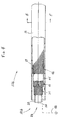
- The catheter of the present invention is designated generally by the
reference numeral 10 in FIGURE 1. Thecatheter 10 is depicted with the central section broken away. Consequently, FIGURE 1 gives no indication of the length of thecatheter 10 relative to its width. The length of thecatheter 10 is selectable in accordance with the length of known catheters which are used for the same or similar applications. Generally, thecatheter 10 defines aproximal end 12, adistal end 14, and anouter surface 16, with the outer surface being approximately cylindrical in shape within local regions along the length of thecatheter 10. - In a preferred embodiment, the
outer surface 16 of thecatheter 10 is defined by an outer electrically insulatingsurface layer 17 which fits snugly over an innercomposite structure 18. For most uses of this invention, polyurethane is a preferable material for the outer insulatinglayer 17. However, there are a large number of suitable materials that would be well known to those skilled in the art. For example, polyester ether ketone is a preferable material for the insulatinglayer 17 in ablative catheters. Theouter surface layer 17, in this embodiment, is mechanically strippable at aselectable contact region 20 so as to expose the outer layer of the innercomposite structure 18 over theselectable contact region 20. In the example illustrated in FIGURE 1,sensors catheter 10, andsensor 26 is attached to thedistal end 14. - One can best see the inner
composite structure 18a of a preferred embodiment in FIGURES 2 and 3. FIGURE 2 is a side view of a section of thecatheter 10a with partial cutaway sections which reveal the innercomposite structure 18a. FIGURE 3 provides a cross-sectional view of thecatheter 10a. Thecatheter 10a is generally comprised of a central flexible, electricallynon-conductive core 28 disposed along thecatheter axis 30. (The term "non-conductive" is used to refer to any material which is generally known to be an insulator, or to a fluid or gas-filled or vacuum space which also acts as an insulator.) In one embodiment of the invention, thecore 28 is a solid electrical insulator, and in other embodiments the electricallyinsulative core 28 defines one or more hollow paths that extend between theproximal end 12 and thedistal end 14 of thecatheter 10a. In a preferred embodiment, the centralnon-conductive core 28 is flexible electricallyinsulative tubing 32 which defines acentral lumen 33 that extends along thecatheter axis 30. In the preferred embodiment the core is made of polyurethane. - The
non-conductive core 28 has a layer of strandedfibers 34 on its outer surface. Stranding optical fibers in a fiberoptic catheter is taught by Wardle et al. in U.S. Patent No. 5,415,653 entitled "Optical Catheter with Stranded Fibers," and is hereby incorporated by reference in its entirety. The first layer of strandedfibers 34 is comprised of a plurality of fibers, one of which is designated byreference numeral 36 in FIGURE 3. Each fiber, such asfiber 36, in the layer of strandedfibers 34 extends substantially between theproximal end 12 and thedistal end 14 of thecatheter 10a, along non-overlapping, helical paths around the centralnon-conductive core 28. - The stranded
fibers 34 define helical paths with a substantially uniform first pitch angle for allfibers 34 at substantially all points along the helical paths when thecatheter 10a subtends a straight line and is in an unstressed, relaxed state. - Generally, each individual fiber, such as
fiber 36, has a selectable thickness and composition. For example,fiber 38 may have a different thickness from that offiber 36, orfiber 38 may be of a different material from that offiber 36. The layer of strandedfibers 34 is nowhere thicker than the thickness of the thickest fiber. In the example depicted in FIGURES 2 and 3, thefibers 34 are 40 ± 4 electrically conducting wires which are all of approximately equal thickness. The example depicted in FIGURE 3 shows individual adjacent fibers, such asfibers fibers 34, and selectable separations between fibers. The number of fibers are chosen to be greater than 10, preferably 20 or more, and are often chosen in the range of 40, 50, or even greater. In many uses, such as to deliver high voltage defibrillation pulses, the fibers are preferably made from low resistance materials such as platinum, silver or titanium. In this embodiment, the strandedfibers 34 are covered by insulatinglayer 17 described above. - One can best see the inner
composite structure 18b of another preferred embodiment in FIGURES 4 and 5. FIGURE 4 is a side view of a section of the catheter 10b with partial cutaway sections which reveal the innercomposite structure 18b. FIGURE 5 provides a cross-sectional view of the catheter 10b. The catheter 10b is generally comprised of a central flexible, electricallynon-conductive core 28 disposed along thecatheter axis 30, as described above in reference to the first mentioned preferred embodiment. - This embodiment has a first layer of stranded
fibers 34 on the outer surface of the non-conductive core with a second layer of strandedfibers 42 immediately over the first layer of stranded fibers. In this preferred embodiment of the invention, each successive layer of fibers is stranded over the underlying layer in a direction opposite to that of the closest underlying stranded layer. Therefore, according to this preferred embodiment of the invention, the second layer of strandedfibers 42 is stranded over the first layer of strandedfibers 34 in a direction opposite to that of the first layer. The individual fibers of the second layer of strandedfibers 42, and any and all succeeding layers of stranded fibers, are selectable in material and thickness. In a preferred embodiment of the instant invention, there are 38 ± 4 fibers in the first layer and 43 ± 4 fibers in the second layer which are all substantially of equal thickness. The fibers of the first and second layers in this embodiment are preferably of materials with high tensile strength, such as stainless steel. The fibers of the second layer of strandedfibers 42 similarly extend between theproximal end 12 and thedistal end 14 of the catheter 10b along non-overlapping helical paths around the first layer of strandedfibers 34. The second layer of strandedfibers 42 is also stranded such that the plurality of fibers define helical paths of a substantially uniform second pitch for allfibers 42 at substantially all points along the helical paths when the catheter 10b subtends a straight line and is in an unstressed, relaxed state. Since the second layer of strandedfibers 42 is stranded around the first layer of strandedfibers 34 in a direction opposite from that of the direction in which the first layer of strandedfibers 34 is stranded around thenon-conductive core 28, the second pitch is opposite in sign to that of the first pitch. - Furthermore, the magnitude of the second pitch is approximately equal to the magnitude of the first pitch, which is preferably 0.475 inches. The reader should note that it is known in the art that the pitch of layers of stranded optical fibers can be selectively varied to achieve alternative mechanical properties of a fiberoptic catheter. A greater pitch allows one to strand a greater number of fibers at the expense of some flexibility and torquability. Conversely, a smaller pitch leads to greater flexibility, but a smaller number of fibers in the strand. Similarly, in other embodiments of the instant invention, one can select different and nonuniform first and second pitches in order to obtain desired mechanical properties. Preferably, the pitch is much greater than the thickness of the wire (at least 10 times greater, and more typically more than 40 times greater).
- The preferred embodiment depicted by the example of FIGURES 4 and 5 has a first electrically
insulative layer 44 immediately covering the second layer of stranded fibers. Polyurethane is a suitable material forlayer 44 for most uses, or polyester ether ketone for other uses. A third layer offibers 46 is stranded over the outer surface defined by the first electricallyinsulative layer 44 In a preferred embodiment, the third layer of strandedfibers 46 has 40 ± 4 titanium wires, each of which extend substantially between theproximal end 12 and thedistal end 14 of the catheter 10b, along non-overlapping helical paths with a third pitch which is substantially equal in magnitude, but opposite in sign to the second pitch. The third layer of strandedfibers 46 is covered by a second layer of electricallyinsulative material 17 which defines anouter surface 16. When the present embodiment is used as a defibrillation catheter, the second layer of electricallyinsulative material 17 must be capable of withstanding a DC voltage of 1500V applied in 20ms pulses. Alayer 17 made of polyurethane with a thickness of at least 0.0035 inches is suitable for catheter 10b with an outer diameter of 0.077 ± 0.002 inches. - In the preferred embodiments of this invention the outermost layer of stranded fibers has a large number of closely or maximally packed electrically conductive fibers. The fibers are arranged so as to approximate an electrically conductive cylindrical shell. The approximation to a cylindrical shell improves as the number of fibers increases. Conversely, small numbers of fibers cannot provide a good approximation to a cylindrical shell, as one can appreciate by considering the extreme cases of only one, two, three or four fibers.
- The central lumen of the
non-conductive core 28 is adapted to accommodate a plurality of fibers which, in one embodiment, extend between theproximal end 12 and thesensors non-conductive core 28 accommodates electrically conductive wires which extend from theproximal end 12 of the catheter 10b to connect to electrodes on thesensor - The electrodes on
sensor 26 are suitable for mapping the electrical activity of the heart by procedures which are well-known to one skilled in the art of modern electrophysiology. - In practice, the
catheter 10 is guided through a small incision in the body to the internal regions of interest. The flexibleinner core 28, first layer of strandedfibers 34, second layer of strandedfibers 42, first insulatinglayer 44, third layer of strandedfibers 46, andouter surface layer 17 all act in cooperation to transmit torque between theproximal end 12 and thedistal end 14 in a manner known in the art for stranded optical fibers. Depending on the particular application, the electrically conductive fibers of the third (outermost) layer of strandedfibers 46 are electrically connected to a high voltage source, a radio frequency voltage source, signal detection and processing equipment, or other suitable electronic equipment. Thecontact region 20 provides a suitably large surface area for making electrical contact with the internal region of the body of interest. Thecontact region 20 is selectable in both size and location along thecatheter 10 by stripping away the corresponding material from the electrically insulatingsurface layer 17. In addition, other embodiments of the instant invention have a plurality of contact regions, similar to contactregion 20, which are also selectable in size and location. It is important to point out that, unlike prior art ring electrodes, thecontact region 20 does not severely affect the flexibility of the catheter and does not present protruding obstacles. As a specific example, one may connect a high voltage source to the third layer of strandedfibers 46 to deliver defibrillation pulses to a patient's heart through thecontact region 20. The outer insulatinglayer 17 and the first electricallyinsulative layer 44 ensure that the third layer of strandedfibers 46 is electrically isolated everywhere except at theproximal end 12 of thecatheter 10, and at thecontact region 20. - In a preferred embodiment of the instant invention, the first layer of stranded
fibers 34 and the second layer of strandedfibers 42 are electrically isolated from the central lumen by theelectrically insulating core 28, and from the third layer of strandedfibers 46 by thefirst insulative layer 44. In this embodiment, the first layer of strandedfibers 34 and the second layer of strandedfibers 42 have no electrical connections and thus provide primarily mechanical torque transfer properties. In another preferred embodiment, the first layer of strandedfibers 34 and the second layer of strandedfibers 42 are electrically connected to ground as indicated schematically in FIGURE 4 by the reference numeral 48. It can also be readily understood by one of ordinary skill in the art, based upon the teachings of this invention, that thelayers proximal end 12 anddistal end 14 of thecatheter 10, independently of the third layer of strandedfibers 46. Energy transfer along this second channel can be in the form of signals from sensors, for example, or for therapeutic purposes. - In other embodiments of the instant invention, fibers of different materials can be mixed with the electrically conductive fibers. For example, fiber 50 in the third layer of stranded
fibers 46, orfiber 40 of the first layer of stranded fibers could be an optical fiber suited for transferring optical signals between thedistal end 14 and theproximal end 12 of thecatheter 10. A greater number of such optical fibers could be used as necessary. The optical fibers could also be used to deliver therapeutic energy to a tissue site somewhere along the length, or at thedistal end 14, of thecatheter 10, in addition to the above described electrical energy transfer properties of thecatheter 10. - In another embodiment of the instant invention, electrically insulative fibers can be mixed with the electrically conductive fibers. For example, as one may best see in FIGURE 5, the fiber labeled with the reference numeral 50 may be an electrically conductive wire. The fiber 52 may be an insulative fiber,
fiber 54 conductive,fiber 56 insulative, and so on around the third layer offibers 46. This embodiment yields a plurality of separate electrically conductive channels, e.g., fiber 50 would be one channel,fiber 54 another channel, and so on. This embodiment of the instant invention is not limited to the one specific example described above. One could choose the numbers of electrically insulative and conductive fibers, and the specific configuration of those fibers, from among all of the possible permutations to suit the particular application. - In another embodiment of the instant invention, one may utilize a plurality of different fiber types in order to select specific mechanical properties, in addition to the electrical properties of the
catheter 10, to suit a particular application. For example, a fiber such asfiber 40 in the first layer of strandedfibers 34, and any number of other fibers in any of the stranded layers, can be made from certain polymers so as to enhance the lubricity of the corresponding layer. - The preferred embodiment described in detail above, in which a first layer of
fibers 34 is stranded over acentral core 28, followed by a second layer of strandedfibers 42, a first layer ofinsulation 44, a third layer of strandedfibers 46, and finally an outer layer ofinsulation 17, does not limit the invention to that specific configuration. Other embodiments have various numbers of layers of stranded fibers configured with various numbers of intervening electrically insulative layers. Alternatively, the stranded fibers can be provided with an insulating or lubricious coating. - As noted, there are numerous advantages of the catheter of this invention over other catheters for the delivery of electrical energy. The catheter of this invention provides a relatively large surface contact region for transferring electrical energy to an internal region of the body and it is also flexible at the contact region. There are no electrical connections between the contact regions and the wires that transfer the electrical energy to the contact regions, such as is the case with the prior art ring electrodes, thus, enhancing the reliability of the catheter. There are no complicated manufacturing techniques required to ensure that the contact region does not protrude beyond the diameter of the adjacent regions of the catheter, so as not to obstruct the motion of the catheter through narrow paths within the patient's body. The electrically conductive fibers can be closely packed together, so as to approximate a cylindrical sheet conductor.
- A plurality of wires which carry an electrical current to the surface contact region has a lower overall resistance than a single wire of the same material of the same thickness that carries the same amount of current to contact regions. Therefore, the stranded wires allow the current to be spread over a region which approximates a cylindrical shell of current. As one strands wires closer together, one more closely approximates the limit of an electrically conductive cylindrical shell. This is particularly true when the wires are stranded so closely together that they are in contact with the immediately adjacent fibers. In such a case, if the wires do not have insulating outer layers, current can then also flow between wires. This additional degree of freedom for the flow of electrical current leads to an additional decrease in the overall electrical resistance, thus, even more closely approximating a conducting ring while remaining flexible.
- Therefore, this invention minimizes undesirable resistive heating effects while still providing a central lumen for other instruments and sensors, all while maintaining a compact, narrow cross-section.
- In a third preferred embodiment of the instant invention, the
catheter 10c has an outer insulating layer 17c, at least one layer of strandedfibers 34c comprising a plurality of electrically conductive wires, and a non-conductive core 28c which is preferably electrically insulative tubing 32c that defines a central lumen 33 (see FIGURE 6). The plurality of electrically conductive wires can have various configurations. Preferably, the fibers are stranded in nonoverlapping helical paths in a manner as described in the first and second embodiments of this invention. - In this embodiment, all of the fibers of the layer of stranded
fibers 34c are preferably electrically conductive wires that have electrically insulating outer layers, such as outer layer 58. The electrically conductive wires of the layer of strandedfibers 34c are preferably connected at the proximal end to a surgical electro-cautery power unit such that each fiber has a polarity opposite to that of the two adjacent wires. The surgical electro-cautery power unit may be selected from conventionally known power units to provide electrical pulses for cutting tissue. For example,wire 62 has a polarity opposite to that ofwires 60 and 64. Similarly, wire 64 has a polarity opposite to that ofwires 62 and 66, and so on around the entire periphery of thelayer 34c of electrically conductive wires. - One skilled in the art would recognize that other arrangements of the wires of the
layer 34c are possible without departing from the scope or spirit of the invention. For example, electrically non-conductive fibers may be included within the layer of strandedfibers 34c. Such non-conductive fibers may be disposed between electrically conductive wires within the layer of strandedfibers 34c in numerous configurations. In such alternative embodiments, the electrically non-conductive fibers may be disposed between electrically conductive wires to form configurations in which the electrically conductive wires are distributed about thecatheter axis 30 in symmetrical and in asymmetrical patterns. - In another alternative embodiment, the electrically conductive fibers within the layer of stranded
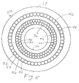
fibers 34c do not have electrically insulating surfaces. Instead, electrically insulating fibers, along with electrically insulating layers 17c and 32c, keep electrically conductive wires of one polarity electrically isolated from wires of the opposite polarity along the length of thecatheter 10c. For example,fibers fiber 62 is an electrically conductive wire attached to the power source at one polarity, and fiber 66 is an electrically conductive wire with the polarity opposite to that ofwire 62. This pattern is repeated around the entire layer of strandedfibers 34c. - FIGURE 6 is an end-on view of the
catheter 10c which illustrates the exposed ends of thewires - In practice, the cutting end of the layer of stranded
fibers 34c is brought into contact with tissue to be cut. Electrical energy is transmitted throughwires catheter 10c to the cutting end at the distal end of thecatheter 10c. An electrical current thus flows through tissue in contact with the tip and between wires of opposite polarities, e.g.,wires fibers 34c are electrically conductive wires, with electrically insulating surfaces, the cutting effect is approximately uniformly distributed around the cutting tip end of the layer of strandedfibers 34c. - In one method of application, the
catheter 10c is used for removing pacing leads for heart pacemakers which had previously been implanted in the patient's body. In such an application, the surgeon slides thecatheter 10c over the pacing lead such that the pacing lead extends along thecentral lumen 33. Since the cutting effect is approximately uniformly distributed around the cutting tip, the surgeon can advance thecatheter 10c along the pacing lead in a substantially rectilinear motion without the need to rotate the catheter by large amounts about thecatheter axis 30. However, one can anticipate that some small angle "back and forth" rotations about thecatheter axis 30 as thecatheter 10c is advanced over the pacing lead can be advantageous in some cases. Therefore, this permits the surgeon to advance the catheter along the pacing lead while cutting scar tissue around the entire circumference of the lead, thus obviating the need to advance the catheter in a spiral motion over the pacing lead. Although this embodiment of the invention was described for removing pacing leads, this embodiment of the invention is also useful for other types of surgery, such as removing tumors, biopsies, and other implant devices. - In the fourth embodiment of the invention, illustrated in FIGURE 7, the catheter 10d has a plurality of layers of stranded fibers. FIGURE 7 is an end-on view of the cutting tip at the distal end. In one example of this embodiment, the layer of stranded
fibers 46d corresponds to the layer of strandedfibers 34c of the third embodiment, thus providing the cutting action. The layers of strandedfibers 34d and 42d correspond to the layers of strandedfibers fibers 34d and 42d provide the mechanical advantages of good maneuverability for a catheter for electro-cautery. - In another example of the fourth preferred embodiment of the invention, substantially all fibers in the layer of stranded
fibers 46d are electrically conductive wires which are in electrical contact with each other. Similarly, the layers of strandedfibers 34d and 42d are substantially all electrically conductive wires which are in electrical contact with the adjacent fibers. Preferably, thelayer 46d is connected at the proximal end to a surgical electro-cautery power unit at one polarity while thelayers 34d and 42d are connected at the opposite polarity. Thelayer 44d is an electrically non-conductive layer which keepslayer 46d electrically isolated fromlayers 34d and 44d along the length of the catheter. Preferably, the layers are stranded in nonoverlapping helical paths in the same manner as in the second embodiment. - In operation, the distal end of the catheter is brought into contact with tissue. The tissue provides a conductive, but high resistance, or high impedance, path for electricity to flow between
layer 46d and layers 34d and 42d at the distal end. The high resistance, or impedance, of the tissue in contact with the catheter 10d at its distal end results in a rapid absorption of energy by the tissue which acts to provide the cutting effect. - Catheters according to the fourth embodiment of the invention may be used according to the same method of pacing lead removal as described with respect to the third embodiment. In addition, this embodiment of the invention is also useful for other types of surgery, such as removing tumors, biopsies, and other implant devices.
- One skilled in the art would recognize that alternative arrangements of pluralities of layers of stranded fibers and electrically non-conductive layers are within the scope and spirit of the instant invention. For example, there may be only two
layers non-conductive layer 44d. There may also be more than three layers of stranded fibers with more than one electrically non-conductive layer disposed between layers of stranded fibers. - Although the invention has been described with reference to specific embodiments, one should realize that these embodiments are illustrative of the application of the principles of the invention. One should recognize from the above description that there are a very large number of modifications and rearrangements of the above-illustrated embodiments which one may devise without departing from the spirit and scope of the invention.
Claims (59)
- A catheter comprising:a core having an axis extending between a proximal end and a distal end of said catheter; anda layer of stranded fibers stranded over said core,
wherein said layer of stranded fibers includes at least one electrically conductive fiber, said fibers being stranded between said proximal end and said distal end, permitting transfer of electrical energy between said proximal end and said distal end of said catheter along said electrically conductive fiber. - A catheter according to claim 1, further comprising a second layer of fibers stranded over said core,
wherein said second layer of stranded fibers is disposed between said first mentioned layer of stranded fibers and said core. - A catheter according to claim 2, further comprising an electrically non-conductive layer, said electrically non-conductive layer being disposed between said first mentioned layer of stranded fibers and said second layer of stranded fibers thereby preventing flow of electrical current between said first mentioned and said second layers of stranded fibers.
- A catheter according to claim 3, further comprising a third layer of stranded fibers stranded over said second layer of stranded fibers,
wherein said third layer of stranded fibers is disposed between said non-conductive layer and said second layer of stranded fibers, said second and third layers of stranded fibers thereby being suitable to provide structural support for said catheter. - A catheter according to claim 4, wherein:said second layer of stranded fibers extends from said proximal end to said distal end along non-overlapping helical paths such that each fiber of said second plurality of fibers has a first pitch at a first perpendicular projection of a point along said axis,said third layer of stranded fibers extends from said proximal end to said distal end along non-overlapping helical paths such that each fiber of said third plurality of fibers has a second pitch at a second perpendicular projection of said point along said axis, wherein said second pitch is substantially equal and opposite to said first pitch,said non-conductive layer is disposed immediately proximate to said third layer of stranded fibers, said third layer of stranded fibers is disposed immediately proximate to said second layer of stranded fibers, and said second layer of stranded fibers is disposed immediately proximate to said core, wherein said core, said second and third layers of stranded fibers, and said non-conductive layer act in cooperation to transmit torque along said axis of said catheter for rotations in both directions about said axis.
- A catheter according to claim 5, wherein substantially all fibers of said first mentioned layer of fibers are electrical conductors such that said first mentioned layer is substantially an electrically conductive layer suitable to transmit electrical energy along said axis of said catheter.
- A catheter according to claim 6, wherein said core defines a hollow path extending between said proximal end and said distal end such that said hollow path can accommodate at least one wire threaded therethrough.
- A catheter according to claim 6, wherein said core defines a plurality of hollow paths extending between said proximal end and said distal end.
- A catheter according to claim 5, further comprising a second electrically non-conductive layer disposed immediately proximate to said first mentioned layer of stranded fibers such that said first mentioned layer of stranded fibers is enclosed substantially within said second non-conductive layer,
said second non-conductive layer thereby preventing flow of electrical current between said first mentioned layer of stranded fibers and a body in contact with an outer surface of said second non-conductive layer. - A catheter according to claim 9, wherein said second non-conductive layer defines an exposed contact region allowing electrical contact to be made with said first mentioned layer of stranded fibers.
- A catheter according to claim 10, wherein said core defines a hollow path extending between said proximal end and said distal end such that said hollow path can accommodate at least one wire threaded therethrough.
- A catheter according to claim 10, wherein said core defines a plurality of hollow paths extending between said proximal end and said distal end.
- A catheter according to claim 11, wherein substantially all of said first mentioned layer of fibers are electrical conductors such that said contact region is suitable to transmit electrical energy between said catheter and a body in contact with said contact region.
- A catheter according to claim 4, wherein at least one of said second and third layers of stranded fibers includes a second electrically conductive fiber thereby providing a path to transmit electrical energy between said proximal and said distal ends of said catheter independently of said first mentioned layer of stranded fibers.
- A catheter according to claim 14, further comprising a grounding lead in electrical contact with said at least one second electrically conductive fiber so as to be suitable to shield electric fields.
- A catheter according to claim 1, wherein said core is an electrically non-conductive core.
- A catheter according to claim 1, wherein said core defines at least one lumen between said proximal end and said distal end of said catheter.
- A catheter according to claim 1, wherein said stranded fibers extend between said proximal end and said distal end of said catheter along non-overlapping helical paths such that said helical paths define a substantially uniform pitch.
- A catheter according to claim 1, whereinsaid fibers are all substantially equal in thickness,said layer has a maximum thickness equal to a thickness of one of said fibers, anda number of fibers in said layer is substantially equal to a maximum number of fibers of said thickness that can fit within said layer so as to approximate an electrically conductive cylindrical shell.
- A catheter according to claim 1, wherein said layer is comprised of a plurality of contiguous non-overlapping electrically conductive fibers.
- A catheter according to claim 1, further comprising an electrically non-conductive layer disposed immediately proximate to said layer of stranded fibers such that said layer of stranded fibers is enclosed substantially within said non-conductive layer,
said non-conductive layer thereby preventing flow of electrical current between said layer of stranded fibers and a body in contact with an outer surface of said non-conductive layer. - A catheter according to claim 21, wherein said non-conductive layer defines an exposed contact region allowing electrical contact to be made with said layer of stranded fibers.
- A catheter according to claim 1, wherein said electrically conductive fiber has a coating which is suitable to make said fiber lubricious.
- A catheter according to claim 1, wherein said electrically conductive fiber has an electrically insulative coating suitable to impede flow of electricity between said conductive fiber and adjacent fibers.
- A catheter according to claim 1, wherein said layer of fibers includes an optical fiber which is suited to transmit optical energy between said proximal end and said distal end of said catheter.
- A catheter according to claim 1, wherein said layer of fibers includes a polymer monofilament fiber which is suited to provide lubricity to said layer.
- A catheter according to claim 1, wherein said layer of fibers includes a plurality of electrically conductive fibers.
- A catheter according to claim 1, wherein said layer of fibers includes a plurality of electrically conductive fibers and a plurality of electrically insulative fibers, said plurality of electrically conductive fibers being disposed such that they are spaced apart by said plurality of electrically insulative fibers to form a plurality of electrically conductive paths within said layer of stranded fibers.
- A method of making a catheter for electrical energy delivery comprising the steps of:stranding a first plurality of fibers over a core such that said first plurality of fibers extends between a proximal end and a distal end of said catheter along non-overlapping helical paths, wherein said helical paths define a first rotation direction;stranding a second plurality of fibers over said first plurality of fibers such that said second plurality of fibers extends between a proximal end and a distal end of said catheter along non-overlapping helical paths, wherein said helical paths define a second rotation direction, and said second rotation direction is opposite to said first rotation direction;disposing an electrically non-conductive layer over said second plurality of fibers;stranding a third plurality of fibers over said first electrically nonconductive layer, wherein said third plurality of fibers includes an electrically conductive fiber.
- A method of making a catheter according to claim 29, further comprising the steps of:disposing a second electrically non-conductive layer over said third plurality of fibers; andstripping away a portion of said second non-conductive layer to form a contact region such that said third plurality of fibers can be contacted at said contact region.
- A method of making a catheter according to claim 29, wherein at least one fiber of said first and second plurality of fibers is an electrically conductive fiber capable of transmitting electrical energy between said proximal and said distal ends of said catheter, independently of said third plurality of fibers.
- A method of making a catheter according to claim 31, further comprising the step of connecting a grounding lead to said at least one electrically conductive fiber of said first and said second plurality of fibers so as to provide a shield for electric fields.
- A method of making a catheter for electrical energy delivery comprising the step of stranding a plurality of fibers between a proximal end and a distal end of said catheter over a core, wherein said plurality of fibers includes at least one electrically conductive fiber which is capable of transmitting electrical energy between said proximal and said distal ends of said catheter.
- A method of making a catheter according to claim 33, wherein said plurality of fibers includes at least one optical fiber which is capable of transmitting optical energy between said proximal and said distal ends of said catheter.
- A method of making a catheter according to claim 33, wherein said electrically conductive fiber has a coating suited to make said fiber lubricious.
- A method of making a catheter according to claim 33, wherein said electrically conductive fiber has an insulative coating suited to impede flow of electricity between said electrically conductive fiber and adjacent fibers.
- A method of making a catheter according to claim 33, wherein said plurality of fibers includes a polymer monofilament fiber suited to provide lubricity to said layer of stranded fibers.
- A method of making a catheter according to claim 33, wherein said core is an electrically non-conductive core.
- A method of making a catheter according to claim 33, wherein said core defines at least one lumen between said proximal end and said distal end of said catheter.
- A method of making a catheter according to claim 33, wherein said layer of stranded fibers extends between said proximal end and said distal end of said catheter along non-overlapping helical paths such that said helical paths define a substantially uniform pitch.
- A method of making a catheter according to claim 33, whereinsaid fibers are all substantially equal in thickness,said layer has a maximum thickness equal to a thickness of one of said fibers, anda number of fibers in said layer is substantially equal to a maximum number of fibers of said thickness that can fit within said layer thereby approximating an electrically conductive cylindrical shell.
- A method of making a catheter according to claim 33, wherein said layer is comprised of a plurality of contiguous non-overlapping conductive fibers.
- A method of making a catheter according to claim 33, further comprising the step of disposing an electrically non-conductive layer immediately proximate to said layer of stranded fibers such that said layer of stranded fibers is enclosed substantially within said non-conductive layer,
said non-conductive layer thereby preventing flow of electrical current between said first mentioned layer of stranded fibers and a body in contact with an outer surface of said non-conductive layer. - A method of making a catheter according to claim 43, further comprising the step of stripping said non-conductive layer to expose a contact region suitable to make electrical contact with said first mentioned layer of stranded fibers.
- A catheter comprising:a core having an axis extending between a proximal end and a distal end of said catheter;a layer of stranded fibers having a plurality of fibers that extend between said proximal end and said distal end of said catheter over said core; andan electrically non-conductive layer disposed over said layer of stranded fibers so as to prevent a flow of electrical current in a radial direction through said electrically non-conductive layer,
wherein said layer of stranded fibers includes a plurality of electrically conductive wires constructed and arranged to present an electro-cautery cutting end at said distal end of said catheter. - A catheter according to claim 45, wherein substantially all fibers of said layer of stranded fibers are electrically conductive wires with electrically insulating outer layers so as to electrically isolate each wire along a length of the catheter from the proximal end to said distal end, said electrically conductive wires are constructed and arranged to present an electro-cautery cutting end at said distal end of said catheter.
- A catheter according to claim 46, wherein said core defines a hollow path extending between said proximal end and said distal end of said catheter such that said hollow path can accommodate at least a pacing lead threaded therethrough.
- A catheter according to claim 47, wherein said fibers of said layer of stranded fibers extend from said proximal end to said distal end of said catheter along non-overlapping helical paths.
- A catheter according to claim 48, wherein each electrically conductive wire has a first electrical polarity which is opposite in polarity to a second electrical polarity of each adjacent electrical wire.
- A catheter according to claim 45, wherein said plurality of electrically conductive wires are constructed and arranged to form a plurality of electrically conductive paths which are electrically isolated from each other along a length of said catheter from said proximal end to said distal end, at least one of said plurality of conductive paths has a first electrical polarity which is opposite in polarity to a second electrical polarity of at least one of said plurality of conductive paths.
- A catheter according to claim 50, wherein said core defines a hollow path extending between said proximal end and said distal end such that said hollow path can accommodate at least a pacing lead threaded therethrough.
- A catheter according to claim 51, wherein said fibers of said layer of stranded fibers extends from said proximal end to said distal end along non-overlapping helical paths.
- A catheter according to claim 45, further comprising:a second layer of stranded fibers having a plurality of fibers that extend between said proximal end and said distal end of said catheter over said core, said second layer of stranded fibers is disposed between said first mentioned layer of stranded fibers and said core; anda second electrically non-conductive layer disposed between said first mentioned layer of stranded fibers and said second layer of stranded fibers thereby preventing flow of electrical current between said first mentioned and said second layers of stranded fibers.
- A catheter according to claim 53, wherein said second layer of stranded fibers includes a plurality of electrically conductive wires having a first electrical polarity which is opposite in polarity to a second electrical polarity of said plurality of electrically conductive wires of said first mentioned layer of stranded fibers, said first mentioned and said second layers of stranded fibers present an electro-cautery cutting end at said distal end of said catheter.
- A catheter according to claim 54, wherein substantially all fibers of said first mentioned layer of stranded fibers and said second layer of stranded fibers are electrically conductive wires.
- A catheter according to claim 55, wherein said core defines a hollow path extending between said proximal end and said distal end such that said hollow path can accommodate at least a pacing lead threaded therethrough.
- A catheter according to claim 56, whereinsaid fibers of said first mentioned layer of stranded fibers extend from said proximal end to said distal end of said catheter along non-overlapping helical paths defining a first rotation direction,said fibers of said second layer of stranded fibers extend from said proximal end to said distal end of said catheter along non-overlapping helical paths defining a second rotation direction that is approximately equal and opposite to said first rotation direction.
- A catheter according to claim 57, further comprising:a third layer of stranded fibers having a plurality of fibers that extend between said proximal end and said distal end of said catheter over said core,
wherein said third layer of stranded fibers is disposed between said second layer of stranded fibers and said core, andsaid fibers of said third layer of stranded fibers extend from said proximal end to said distal end of said catheter along non-overlapping helical paths defining a third rotation direction that is approximately equal and opposite to said second rotation direction so as to act in cooperation with said first mentioned and said second layers of stranded fibers to transmit torque along said axis of said catheter under rotations in both directions about said axis. - A method of pacing lead removal comprising the steps of:threading a free end of a pacing lead through a lumen of an electro-cautery catheter such that a cutting end of said electro-cautery catheter is in contact with tissue proximate to an attached end of said pacing lead; andadvancing said pacing lead in a substantially rectilinear motion along the pacing lead as said electro-cautery catheter cuts tissue proximate to said attached end of said pacing lead with only small-angle rotations of said electro-cautery catheter about said pacing lead.
Priority Applications (1)
| Application Number | Priority Date | Filing Date | Title |
|---|---|---|---|
| EP05010062A EP1598024A3 (en) | 1996-06-12 | 1997-06-11 | Catheter for delivery of electric energy and a process for manufacturing the same |
Applications Claiming Priority (2)
| Application Number | Priority Date | Filing Date | Title |
|---|---|---|---|
| US627799 | 1996-06-12 | ||
| US08/662,799 US5824026A (en) | 1996-06-12 | 1996-06-12 | Catheter for delivery of electric energy and a process for manufacturing same |
Related Child Applications (2)
| Application Number | Title | Priority Date | Filing Date |
|---|---|---|---|
| EP05010062A Division EP1598024A3 (en) | 1996-06-12 | 1997-06-11 | Catheter for delivery of electric energy and a process for manufacturing the same |
| EP05010062.7 Division-Into | 2005-05-09 |
Publications (3)
| Publication Number | Publication Date |
|---|---|
| EP0812575A2 true EP0812575A2 (en) | 1997-12-17 |
| EP0812575A3 EP0812575A3 (en) | 1998-04-15 |
| EP0812575B1 EP0812575B1 (en) | 2011-02-16 |
Family
ID=24659271
Family Applications (2)
| Application Number | Title | Priority Date | Filing Date |
|---|---|---|---|
| EP97109491A Expired - Lifetime EP0812575B1 (en) | 1996-06-12 | 1997-06-11 | RF ablation catheter and manufacturing process |
| EP05010062A Withdrawn EP1598024A3 (en) | 1996-06-12 | 1997-06-11 | Catheter for delivery of electric energy and a process for manufacturing the same |
Family Applications After (1)
| Application Number | Title | Priority Date | Filing Date |
|---|---|---|---|
| EP05010062A Withdrawn EP1598024A3 (en) | 1996-06-12 | 1997-06-11 | Catheter for delivery of electric energy and a process for manufacturing the same |
Country Status (3)
| Country | Link |
|---|---|
| US (2) | US5824026A (en) |
| EP (2) | EP0812575B1 (en) |
| DE (1) | DE69740122D1 (en) |
Cited By (1)
| Publication number | Priority date | Publication date | Assignee | Title |
|---|---|---|---|---|
| US6183469B1 (en) | 1997-08-27 | 2001-02-06 | Arthrocare Corporation | Electrosurgical systems and methods for the removal of pacemaker leads |
Families Citing this family (164)
| Publication number | Priority date | Publication date | Assignee | Title |
|---|---|---|---|---|
| US5683366A (en) | 1992-01-07 | 1997-11-04 | Arthrocare Corporation | System and method for electrosurgical tissue canalization |
| DK0886535T3 (en) | 1996-11-27 | 2006-11-27 | Cook Vascular Tm Inc | Radio frequency dilator cap |
| US6047700A (en) | 1998-03-30 | 2000-04-11 | Arthrocare Corporation | Systems and methods for electrosurgical removal of calcified deposits |
| US6238340B1 (en) * | 1998-05-19 | 2001-05-29 | Eckhard Alt | Composite materials for avoidance of unwanted radiation amplification |
| US8244370B2 (en) * | 2001-04-13 | 2012-08-14 | Greatbatch Ltd. | Band stop filter employing a capacitor and an inductor tank circuit to enhance MRI compatibility of active medical devices |
| US6216045B1 (en) | 1999-04-26 | 2001-04-10 | Advanced Neuromodulation Systems, Inc. | Implantable lead and method of manufacture |
| US6304784B1 (en) * | 1999-06-15 | 2001-10-16 | Arizona Board Of Regents, Acting For And On Behalf Of Arizona State University | Flexible probing device and methods for manufacturing the same |
| US7149585B2 (en) * | 2001-03-30 | 2006-12-12 | Micronet Medical, Inc. | Lead body and method of lead body construction |
| US7555349B2 (en) * | 2000-09-26 | 2009-06-30 | Advanced Neuromodulation Systems, Inc. | Lead body and method of lead body construction |
| US9295828B2 (en) | 2001-04-13 | 2016-03-29 | Greatbatch Ltd. | Self-resonant inductor wound portion of an implantable lead for enhanced MRI compatibility of active implantable medical devices |
| CA2482202C (en) | 2001-04-13 | 2012-07-03 | Surgi-Vision, Inc. | Systems and methods for magnetic-resonance-guided interventional procedures |
| DE60213457T2 (en) | 2001-12-03 | 2007-10-18 | Ekos Corp., Bothell | ULTRASONIC CATHETER FOR SMALL VESSELS |
| WO2003072165A2 (en) | 2002-02-28 | 2003-09-04 | Ekos Corporation | Ultrasound assembly for use with a catheter |
| US6978174B2 (en) | 2002-04-08 | 2005-12-20 | Ardian, Inc. | Methods and devices for renal nerve blocking |
| US8145317B2 (en) | 2002-04-08 | 2012-03-27 | Ardian, Inc. | Methods for renal neuromodulation |
| US7620451B2 (en) | 2005-12-29 | 2009-11-17 | Ardian, Inc. | Methods and apparatus for pulsed electric field neuromodulation via an intra-to-extravascular approach |
| US7162303B2 (en) | 2002-04-08 | 2007-01-09 | Ardian, Inc. | Renal nerve stimulation method and apparatus for treatment of patients |
| US8145316B2 (en) | 2002-04-08 | 2012-03-27 | Ardian, Inc. | Methods and apparatus for renal neuromodulation |
| US8150519B2 (en) | 2002-04-08 | 2012-04-03 | Ardian, Inc. | Methods and apparatus for bilateral renal neuromodulation |
| US7853333B2 (en) | 2002-04-08 | 2010-12-14 | Ardian, Inc. | Methods and apparatus for multi-vessel renal neuromodulation |
| US8131371B2 (en) | 2002-04-08 | 2012-03-06 | Ardian, Inc. | Methods and apparatus for monopolar renal neuromodulation |
| US8150520B2 (en) | 2002-04-08 | 2012-04-03 | Ardian, Inc. | Methods for catheter-based renal denervation |
| US7653438B2 (en) | 2002-04-08 | 2010-01-26 | Ardian, Inc. | Methods and apparatus for renal neuromodulation |
| US20040082859A1 (en) | 2002-07-01 | 2004-04-29 | Alan Schaer | Method and apparatus employing ultrasound energy to treat body sphincters |
| AU2002952146A0 (en) * | 2002-10-17 | 2002-10-31 | Cochlear Limited | Stretchable conducting lead |
| WO2004060448A2 (en) | 2003-01-03 | 2004-07-22 | Ekos Corporation | Ultrasonic catheter with axial energy field |
| US6920361B2 (en) * | 2003-02-14 | 2005-07-19 | Medtronic, Inc. | Reverse wound electrodes |
| EP1619995A2 (en) | 2003-04-22 | 2006-02-01 | Ekos Corporation | Ultrasound enhanced central venous catheter |
| US7087895B1 (en) * | 2003-06-07 | 2006-08-08 | Musc Foundation For Research Development | Electrospray ionization using pointed fibers |
| US20050027339A1 (en) * | 2003-07-29 | 2005-02-03 | Micronet Medical, Inc. | System and method for providing a medical lead body |
| US20050027340A1 (en) * | 2003-07-29 | 2005-02-03 | Micronet Medical, Inc. | System and method for providing a medical lead body having dual conductor layers |
| US20050027341A1 (en) * | 2003-07-29 | 2005-02-03 | Micronet Medical, Inc. | System and method for providing a medical lead body having conductors that are wound in opposite directions |
| US7229437B2 (en) * | 2003-09-22 | 2007-06-12 | St. Jude Medical, Atrial Fibrillation Division, Inc. | Medical device having integral traces and formed electrodes |
| US7234225B2 (en) * | 2003-09-22 | 2007-06-26 | St. Jude Medical, Atrial Fibrillation Division, Inc. | Method for manufacturing medical device having embedded traces and formed electrodes |
| US8147486B2 (en) | 2003-09-22 | 2012-04-03 | St. Jude Medical, Atrial Fibrillation Division, Inc. | Medical device with flexible printed circuit |
| US11819192B2 (en) | 2004-03-23 | 2023-11-21 | Boston Scientific Scimed, Inc. | In-vivo visualization system |
| ES2409160T3 (en) | 2004-03-23 | 2013-06-25 | Boston Scientific Limited | Live View System |
| US7922654B2 (en) | 2004-08-09 | 2011-04-12 | Boston Scientific Scimed, Inc. | Fiber optic imaging catheter |
| JP4460606B2 (en) * | 2004-09-17 | 2010-05-12 | ザ スペクトラネティックス コーポレイション | Apparatus and method for directional delivery of laser energy |
| US8545488B2 (en) * | 2004-09-17 | 2013-10-01 | The Spectranetics Corporation | Cardiovascular imaging system |
| US8628519B2 (en) | 2004-09-17 | 2014-01-14 | The Spectranetics Corporation | Rapid exchange bias laser catheter design |
| US20060089692A1 (en) * | 2004-10-21 | 2006-04-27 | Medtronic, Inc. | Implantable medical lead with stylet guide tube |
| US7761170B2 (en) * | 2004-10-21 | 2010-07-20 | Medtronic, Inc. | Implantable medical lead with axially oriented coiled wire conductors |
| US20060089696A1 (en) * | 2004-10-21 | 2006-04-27 | Medtronic, Inc. | Implantable medical lead with reinforced outer jacket |
| US7831311B2 (en) * | 2004-10-21 | 2010-11-09 | Medtronic, Inc. | Reduced axial stiffness implantable medical lead |
| US7519432B2 (en) * | 2004-10-21 | 2009-04-14 | Medtronic, Inc. | Implantable medical lead with helical reinforcement |
| WO2006052940A2 (en) | 2004-11-05 | 2006-05-18 | Asthmatx, Inc. | Medical device with procedure improvement features |
| US7949407B2 (en) | 2004-11-05 | 2011-05-24 | Asthmatx, Inc. | Energy delivery devices and methods |
| US20070093802A1 (en) * | 2005-10-21 | 2007-04-26 | Danek Christopher J | Energy delivery devices and methods |
| US20100312129A1 (en) | 2005-01-26 | 2010-12-09 | Schecter Stuart O | Cardiovascular haptic handle system |
| US20060167529A1 (en) | 2005-01-26 | 2006-07-27 | Schecter Stuart O | Method and algorithm for defining the pathologic state from a plurality of intrinsically and extrinsically derived signals |
| US20060178674A1 (en) * | 2005-02-08 | 2006-08-10 | Mcintyre John | Surgical apparatus having configurable portions |
| US7571010B2 (en) | 2005-05-06 | 2009-08-04 | Cardiac Pacemakers, Inc. | Cable electrode assembly for a lead terminal and method therefor |
| US9295833B2 (en) * | 2005-05-31 | 2016-03-29 | St. Jude Medical, AB | Implantable medical lead |
| US20060282112A1 (en) * | 2005-06-09 | 2006-12-14 | Stephen Griffin | Method and apparatus for enhanced electrolytic detachment |
| US20070038279A1 (en) * | 2005-08-15 | 2007-02-15 | Fifer Daniel W | Electrodes for implantable medical devices |
| US7901441B2 (en) | 2005-10-18 | 2011-03-08 | Boston Scientific Scimed, Inc. | Method of using an imaging catheter to conduct photodynamic procedures |
| WO2007089714A2 (en) * | 2006-01-27 | 2007-08-09 | The Spectranetics Corporation | Interventional devices and methods for laser ablation |
| WO2007139479A1 (en) * | 2006-06-01 | 2007-12-06 | Cathprint Ab | Tubular catheter for invasive use and manufacturing method therefor |
| DE102006029864A1 (en) * | 2006-06-28 | 2008-01-03 | Biotronik Crm Patent Ag | Electrode device for electrodascularosis and / or therapy |
| US7931647B2 (en) | 2006-10-20 | 2011-04-26 | Asthmatx, Inc. | Method of delivering energy to a lung airway using markers |
| US20100016935A1 (en) * | 2006-10-25 | 2010-01-21 | Hans Strandberg | Medical implantable lead |
| US8961551B2 (en) | 2006-12-22 | 2015-02-24 | The Spectranetics Corporation | Retractable separating systems and methods |
| US9028520B2 (en) | 2006-12-22 | 2015-05-12 | The Spectranetics Corporation | Tissue separating systems and methods |
| US8104483B2 (en) * | 2006-12-26 | 2012-01-31 | The Spectranetics Corporation | Multi-port light delivery catheter and methods for the use thereof |
| US8235983B2 (en) | 2007-07-12 | 2012-08-07 | Asthmatx, Inc. | Systems and methods for delivering energy to passageways in a patient |
| US9848952B2 (en) | 2007-10-24 | 2017-12-26 | The Spectranetics Corporation | Liquid light guide catheter having biocompatible liquid light guide medium |
| US9066742B2 (en) | 2007-11-09 | 2015-06-30 | The Spectranetics Corporation | Intra-vascular device with pressure detection capabilities using pressure sensitive material |
| WO2009065078A1 (en) * | 2007-11-14 | 2009-05-22 | Pathway Medical Technologies, Inc. | Delivery and administration of compositions using interventional catheters |
| WO2009072060A1 (en) | 2007-12-06 | 2009-06-11 | Koninklijke Philips Electronics N.V. | Apparatus, method and computer program for applying energy to an object |
| JP5562249B2 (en) * | 2007-12-06 | 2014-07-30 | コーニンクレッカ フィリップス エヌ ヴェ | Apparatus, method, and computer program for applying energy to an object |
| WO2009085486A1 (en) * | 2007-12-30 | 2009-07-09 | St. Jude Medical, Atrial Fibrillation Division, Inc. | Catheter shaft with multiple reinforcing layers and method of its manufacture |
| US8431057B2 (en) | 2007-12-30 | 2013-04-30 | St. Jude Medical, Atrial Fibrillation Division, Inc. | Catheter shaft and method of its manufacture |
| US8647323B2 (en) * | 2007-12-30 | 2014-02-11 | St. Jude Medical, Atrial Fibrillation Division, Inc. | Catheter shaft with multiple reinforcing layers and method of its manufacture |
| US10080889B2 (en) | 2009-03-19 | 2018-09-25 | Greatbatch Ltd. | Low inductance and low resistance hermetically sealed filtered feedthrough for an AIMD |
| US9108066B2 (en) | 2008-03-20 | 2015-08-18 | Greatbatch Ltd. | Low impedance oxide resistant grounded capacitor for an AIMD |
| US8979828B2 (en) | 2008-07-21 | 2015-03-17 | The Spectranetics Corporation | Tapered liquid light guide |
| US9421065B2 (en) | 2008-04-02 | 2016-08-23 | The Spectranetics Corporation | Liquid light-guide catheter with optically diverging tip |
| US20090270956A1 (en) * | 2008-04-25 | 2009-10-29 | Pacesetter, Inc. | Implantable medical lead configured for improved mri safety |
| US10092169B2 (en) | 2008-07-08 | 2018-10-09 | Karl Storz Imaging, Inc. | Solid state variable direction of view endoscope |
| US8771177B2 (en) * | 2008-07-08 | 2014-07-08 | Karl Storz Imaging, Inc. | Wide angle flexible endoscope |
| US8244375B2 (en) * | 2008-08-25 | 2012-08-14 | Pacesetter, Inc. | MRI compatible lead |
| US20100114275A1 (en) * | 2008-10-30 | 2010-05-06 | Pacesetter, Inc. | Implantable medical lead including winding for improved mri safety |
| US20100114081A1 (en) | 2008-11-05 | 2010-05-06 | Spectranetics | Biasing laser catheter: monorail design |
| US9408665B2 (en) * | 2008-12-12 | 2016-08-09 | The Spectranetics Corporation | Offset catheter |
| US8702773B2 (en) | 2008-12-17 | 2014-04-22 | The Spectranetics Corporation | Eccentric balloon laser catheter |
| US20100168739A1 (en) * | 2008-12-31 | 2010-07-01 | Ardian, Inc. | Apparatus, systems, and methods for achieving intravascular, thermally-induced renal neuromodulation |
| US8652129B2 (en) | 2008-12-31 | 2014-02-18 | Medtronic Ardian Luxembourg S.A.R.L. | Apparatus, systems, and methods for achieving intravascular, thermally-induced renal neuromodulation |
| WO2010080886A1 (en) | 2009-01-09 | 2010-07-15 | Recor Medical, Inc. | Methods and apparatus for treatment of mitral valve in insufficiency |
| US9084883B2 (en) * | 2009-03-12 | 2015-07-21 | Cardiac Pacemakers, Inc. | Thin profile conductor assembly for medical device leads |
| WO2011049684A1 (en) * | 2009-10-19 | 2011-04-28 | Cardiac Pacemakers, Inc. | Mri compatible tachycardia lead |
| CN102596320B (en) | 2009-10-30 | 2016-09-07 | 瑞蔻医药有限公司 | Method and apparatus by percutaneous ultrasound ripple Renal denervation treatment hypertension |
| EP2519311A1 (en) | 2009-12-30 | 2012-11-07 | Cardiac Pacemakers, Inc. | Mri-conditionally safe medical device lead |
| CN102655908B (en) | 2009-12-31 | 2015-04-22 | 心脏起搏器公司 | MRI conditionally safe lead with multi-layer conductor |
| US8391994B2 (en) | 2009-12-31 | 2013-03-05 | Cardiac Pacemakers, Inc. | MRI conditionally safe lead with low-profile multi-layer conductor for longitudinal expansion |
| US8825181B2 (en) | 2010-08-30 | 2014-09-02 | Cardiac Pacemakers, Inc. | Lead conductor with pitch and torque control for MRI conditionally safe use |
| US10765473B2 (en) | 2010-11-08 | 2020-09-08 | Baylis Medical Company Inc. | Electrosurgical device having a lumen |
| JP6063875B2 (en) | 2011-02-24 | 2017-01-18 | エキシモ メディカル リミテッド | Hybrid catheter for tissue resection |
| US10596369B2 (en) | 2011-03-01 | 2020-03-24 | Greatbatch Ltd. | Low equivalent series resistance RF filter for an active implantable medical device |
| US10272252B2 (en) | 2016-11-08 | 2019-04-30 | Greatbatch Ltd. | Hermetic terminal for an AIMD having a composite brazed conductive lead |
| US9427596B2 (en) | 2013-01-16 | 2016-08-30 | Greatbatch Ltd. | Low impedance oxide resistant grounded capacitor for an AIMD |
| US10350421B2 (en) | 2013-06-30 | 2019-07-16 | Greatbatch Ltd. | Metallurgically bonded gold pocket pad for grounding an EMI filter to a hermetic terminal for an active implantable medical device |
| US11198014B2 (en) | 2011-03-01 | 2021-12-14 | Greatbatch Ltd. | Hermetically sealed filtered feedthrough assembly having a capacitor with an oxide resistant electrical connection to an active implantable medical device housing |
| US9931514B2 (en) | 2013-06-30 | 2018-04-03 | Greatbatch Ltd. | Low impedance oxide resistant grounded capacitor for an AIMD |
| US8942828B1 (en) | 2011-04-13 | 2015-01-27 | Stuart Schecter, LLC | Minimally invasive cardiovascular support system with true haptic coupling |
| US9050089B2 (en) * | 2011-05-31 | 2015-06-09 | Covidien Lp | Electrosurgical apparatus with tissue site sensing and feedback control |
| US9245668B1 (en) * | 2011-06-29 | 2016-01-26 | Cercacor Laboratories, Inc. | Low noise cable providing communication between electronic sensor components and patient monitor |
| US20130053838A1 (en) * | 2011-08-22 | 2013-02-28 | William T. Kuo | Interventional radiologic devices and methods for embedded filter removal |
| US20130072924A1 (en) * | 2011-09-20 | 2013-03-21 | Bsd Medical Corporation | Ablation antenna |
| US8825179B2 (en) | 2012-04-20 | 2014-09-02 | Cardiac Pacemakers, Inc. | Implantable medical device lead including a unifilar coiled cable |
| US8954168B2 (en) | 2012-06-01 | 2015-02-10 | Cardiac Pacemakers, Inc. | Implantable device lead including a distal electrode assembly with a coiled component |
| US10013082B2 (en) | 2012-06-05 | 2018-07-03 | Stuart Schecter, LLC | Operating system with haptic interface for minimally invasive, hand-held surgical instrument |
| US9101374B1 (en) | 2012-08-07 | 2015-08-11 | David Harris Hoch | Method for guiding an ablation catheter based on real time intracardiac electrical signals and apparatus for performing the method |
| JP6069499B2 (en) | 2012-08-31 | 2017-02-01 | カーディアック ペースメイカーズ, インコーポレイテッド | Lead wire with low peak MRI heating |
| US9763692B2 (en) | 2012-09-14 | 2017-09-19 | The Spectranetics Corporation | Tissue slitting methods and systems |
| JP6034499B2 (en) | 2012-10-18 | 2016-11-30 | カーディアック ペースメイカーズ, インコーポレイテッド | Inductive element for providing MRI compatibility in implantable medical device leads |
| US10260181B2 (en) * | 2013-01-14 | 2019-04-16 | Lake Region Medical, Inc. | Directional mesh and associated systems |
| USRE46699E1 (en) | 2013-01-16 | 2018-02-06 | Greatbatch Ltd. | Low impedance oxide resistant grounded capacitor for an AIMD |
| US11937873B2 (en) | 2013-03-12 | 2024-03-26 | Boston Scientific Medical Device Limited | Electrosurgical device having a lumen |
| US9291663B2 (en) | 2013-03-13 | 2016-03-22 | The Spectranetics Corporation | Alarm for lead insulation abnormality |
| US9283040B2 (en) | 2013-03-13 | 2016-03-15 | The Spectranetics Corporation | Device and method of ablative cutting with helical tip |
| US9456872B2 (en) | 2013-03-13 | 2016-10-04 | The Spectranetics Corporation | Laser ablation catheter |
| US9883885B2 (en) | 2013-03-13 | 2018-02-06 | The Spectranetics Corporation | System and method of ablative cutting and pulsed vacuum aspiration |
| US10383691B2 (en) | 2013-03-13 | 2019-08-20 | The Spectranetics Corporation | Last catheter with helical internal lumen |
| US9623211B2 (en) | 2013-03-13 | 2017-04-18 | The Spectranetics Corporation | Catheter movement control |
| US10835279B2 (en) | 2013-03-14 | 2020-11-17 | Spectranetics Llc | Distal end supported tissue slitting apparatus |
| US10758308B2 (en) | 2013-03-14 | 2020-09-01 | The Spectranetics Corporation | Controller to select optical channel parameters in a catheter |
| EP3799931A1 (en) | 2013-03-14 | 2021-04-07 | ReCor Medical, Inc. | Ultrasound-based neuromodulation system |
| US11642169B2 (en) | 2013-03-14 | 2023-05-09 | The Spectranetics Corporation | Smart multiplexed medical laser system |
| US9757200B2 (en) | 2013-03-14 | 2017-09-12 | The Spectranetics Corporation | Intelligent catheter |
| US10448999B2 (en) | 2013-03-15 | 2019-10-22 | The Spectranetics Corporation | Surgical instrument for removing an implanted object |
| EP2967634B1 (en) | 2013-03-15 | 2019-06-05 | The Spectranetics Corporation | Surgical instrument for removing an implanted object |
| US10842532B2 (en) | 2013-03-15 | 2020-11-24 | Spectranetics Llc | Medical device for removing an implanted object |
| US9980743B2 (en) | 2013-03-15 | 2018-05-29 | The Spectranetics Corporation | Medical device for removing an implanted object using laser cut hypotubes |
| US9918737B2 (en) | 2013-03-15 | 2018-03-20 | The Spectranetics Corporation | Medical device for removing an implanted object |
| US9668765B2 (en) | 2013-03-15 | 2017-06-06 | The Spectranetics Corporation | Retractable blade for lead removal device |
| US10575743B2 (en) | 2013-04-11 | 2020-03-03 | Biosense Webster (Israel) Ltd. | High electrode density basket catheter |
| US10602947B2 (en) | 2013-04-11 | 2020-03-31 | Biosense Webster (Israel), Ltd. | High density electrode structure |
| US9814618B2 (en) | 2013-06-06 | 2017-11-14 | Boston Scientific Scimed, Inc. | Devices for delivering energy and related methods of use |
| AU2014277623B2 (en) * | 2013-06-07 | 2018-05-17 | Cathrx Ltd | An electrical lead for a catheter and method of manufacturing |
| EP3110499B1 (en) | 2014-02-26 | 2018-01-24 | Cardiac Pacemakers, Inc. | Construction of an mri-safe tachycardia lead |
| EP3113701B1 (en) | 2014-03-03 | 2020-07-22 | The Spectranetics Corporation | Multiple configuration surgical cutting device |
| JP2017513600A (en) * | 2014-04-24 | 2017-06-01 | メドトロニック アーディアン ルクセンブルク ソシエテ ア レスポンサビリテ リミテ | Nerve adjustment catheter with braided shaft and related systems and methods |
| US20170079718A1 (en) | 2014-05-18 | 2017-03-23 | Eximo Medical Ltd. | System for tissue ablation using pulsed laser |
| US10987168B2 (en) | 2014-05-29 | 2021-04-27 | Spectranetics Llc | System and method for coordinated laser delivery and imaging |
| US10405924B2 (en) | 2014-05-30 | 2019-09-10 | The Spectranetics Corporation | System and method of ablative cutting and vacuum aspiration through primary orifice and auxiliary side port |
| WO2016004041A1 (en) * | 2014-07-01 | 2016-01-07 | Boston Scientific Scimed, Inc. | Overlapped braid termination |
| WO2016069754A1 (en) | 2014-10-29 | 2016-05-06 | The Spectranetics Corporation | Laser energy delivery devices including laser transmission detection systems and methods |
| US10492863B2 (en) | 2014-10-29 | 2019-12-03 | The Spectranetics Corporation | Laser energy delivery devices including laser transmission detection systems and methods |
| US10646275B2 (en) | 2014-12-30 | 2020-05-12 | Regents Of The University Of Minnesota | Laser catheter with use of determined material type in vascular system in ablation of material |
| US10646118B2 (en) | 2014-12-30 | 2020-05-12 | Regents Of The University Of Minnesota | Laser catheter with use of reflected light to determine material type in vascular system |
| US10646274B2 (en) | 2014-12-30 | 2020-05-12 | Regents Of The University Of Minnesota | Laser catheter with use of reflected light and force indication to determine material type in vascular system |
| USD765243S1 (en) | 2015-02-20 | 2016-08-30 | The Spectranetics Corporation | Medical device handle |
| USD770616S1 (en) | 2015-02-20 | 2016-11-01 | The Spectranetics Corporation | Medical device handle |
| USD775728S1 (en) | 2015-07-02 | 2017-01-03 | The Spectranetics Corporation | Medical device handle |
| WO2017087149A1 (en) * | 2015-11-18 | 2017-05-26 | Heraeus Deutschland GmbH & Co. KG | Signal and torque transmitting torque coil |
| CN109414292A (en) | 2016-05-05 | 2019-03-01 | 爱克斯莫医疗有限公司 | Device and method for cutting off and/or melting unwanted tissue |
| WO2018063392A1 (en) | 2016-09-30 | 2018-04-05 | Halliburton Energy Services, Inc. | Laser induced graphene coated optical fibers |
| US11666251B2 (en) | 2016-10-31 | 2023-06-06 | Heraeus Deutschland GmbH & Co. KG | Signal and torque transmitting torque coil |
| US10249415B2 (en) | 2017-01-06 | 2019-04-02 | Greatbatch Ltd. | Process for manufacturing a leadless feedthrough for an active implantable medical device |
| US20210121663A1 (en) * | 2017-09-14 | 2021-04-29 | St. Jude Medical, Cardiology Division, Inc. | Torqueable steerable sheaths |
| US10905888B2 (en) | 2018-03-22 | 2021-02-02 | Greatbatch Ltd. | Electrical connection for an AIMD EMI filter utilizing an anisotropic conductive layer |
| US10912945B2 (en) | 2018-03-22 | 2021-02-09 | Greatbatch Ltd. | Hermetic terminal for an active implantable medical device having a feedthrough capacitor partially overhanging a ferrule for high effective capacitance area |
| CN111905236A (en) * | 2020-09-03 | 2020-11-10 | 青岛博泰医疗器械有限责任公司 | Drug balloon catheter system |
Citations (1)
| Publication number | Priority date | Publication date | Assignee | Title |
|---|---|---|---|---|
| US5415653A (en) | 1992-08-26 | 1995-05-16 | Advanced Interventional Systems, Inc. | Optical catheter with stranded fibers |
Family Cites Families (25)
| Publication number | Priority date | Publication date | Assignee | Title |
|---|---|---|---|---|
| DE3134896C2 (en) * | 1981-09-03 | 1985-03-28 | W.C. Heraeus Gmbh, 6450 Hanau | Cable feed for pacemaker electrodes |
| US4559951A (en) * | 1982-11-29 | 1985-12-24 | Cardiac Pacemakers, Inc. | Catheter assembly |
| US5330520A (en) * | 1986-05-15 | 1994-07-19 | Telectronics Pacing Systems, Inc. | Implantable electrode and sensor lead apparatus |
| EP0293499B1 (en) * | 1987-06-01 | 1993-09-01 | Siemens-Elema AB | Implantable multi-pole coaxial lead |
| JPH066115B2 (en) * | 1987-08-27 | 1994-01-26 | 新技術事業団 | Electrodes for implantation in the body |
| EP0312495A3 (en) * | 1987-10-16 | 1989-08-30 | Institut Straumann Ag | Electrical cable for carrying out at least one stimulation and/or measurement in a human or animal body |
| US4981478A (en) * | 1988-09-06 | 1991-01-01 | Advanced Cardiovascular Systems | Composite vascular catheter |
| US5016646A (en) * | 1988-11-29 | 1991-05-21 | Telectronics, N.V. | Thin electrode lead and connections |
| US5005587A (en) * | 1989-11-13 | 1991-04-09 | Pacing Systems, Inc. | Braid Electrode leads and catheters and methods for using the same |
| US5569220A (en) * | 1991-01-24 | 1996-10-29 | Cordis Webster, Inc. | Cardiovascular catheter having high torsional stiffness |
| US5209229A (en) * | 1991-05-20 | 1993-05-11 | Telectronics Pacing Systems, Inc. | Apparatus and method employing plural electrode configurations for cardioversion of atrial fibrillation in an arrhythmia control system |
| US5246014A (en) * | 1991-11-08 | 1993-09-21 | Medtronic, Inc. | Implantable lead system |
| US5324326A (en) * | 1991-11-25 | 1994-06-28 | Telectronics Pacing Systems, Inc. | Pressure sensing pacing lead |
| US5509411A (en) * | 1993-01-29 | 1996-04-23 | Cardima, Inc. | Intravascular sensing device |
| US5330521A (en) * | 1992-06-29 | 1994-07-19 | Cohen Donald M | Low resistance implantable electrical leads |
| US5324323A (en) * | 1992-09-09 | 1994-06-28 | Telectronics Pacing Systems, Inc. | Multiple channel cardiosynchronous myoplasty apparatus |
| US5466252A (en) * | 1992-10-02 | 1995-11-14 | W. L. Gore & Associates, Inc. | Implantable lead |
| US5303704A (en) * | 1992-12-22 | 1994-04-19 | Medtronic, Inc. | Medical electrical lead |
| US5524619A (en) * | 1993-04-01 | 1996-06-11 | Terumo Kabushiki Kaisha | Multielectrode probe |
| DE4428914C2 (en) * | 1993-08-18 | 2000-09-28 | Scimed Life Systems Inc | Thin-walled multi-layer catheter |
| US5417208A (en) * | 1993-10-12 | 1995-05-23 | Arrow International Investment Corp. | Electrode-carrying catheter and method of making same |
| US5443492A (en) * | 1994-02-02 | 1995-08-22 | Medtronic, Inc. | Medical electrical lead and introducer system for implantable pulse generator |
| US5423881A (en) * | 1994-03-14 | 1995-06-13 | Medtronic, Inc. | Medical electrical lead |
| US5483022A (en) * | 1994-04-12 | 1996-01-09 | Ventritex, Inc. | Implantable conductor coil formed from cabled composite wire |
| US5667499A (en) * | 1994-10-04 | 1997-09-16 | Scimed Life Systems, Inc. | Guide catheter unibody |
-
1996
- 1996-06-12 US US08/662,799 patent/US5824026A/en not_active Expired - Lifetime
-
1997
- 1997-06-11 EP EP97109491A patent/EP0812575B1/en not_active Expired - Lifetime
- 1997-06-11 DE DE69740122T patent/DE69740122D1/en not_active Expired - Lifetime
- 1997-06-11 EP EP05010062A patent/EP1598024A3/en not_active Withdrawn
- 1997-06-12 US US08/873,753 patent/US5836946A/en not_active Expired - Lifetime
Patent Citations (1)
| Publication number | Priority date | Publication date | Assignee | Title |
|---|---|---|---|---|
| US5415653A (en) | 1992-08-26 | 1995-05-16 | Advanced Interventional Systems, Inc. | Optical catheter with stranded fibers |
Cited By (2)
| Publication number | Priority date | Publication date | Assignee | Title |
|---|---|---|---|---|
| US6183469B1 (en) | 1997-08-27 | 2001-02-06 | Arthrocare Corporation | Electrosurgical systems and methods for the removal of pacemaker leads |
| US6379351B1 (en) | 1997-08-27 | 2002-04-30 | Arthrocare Corporation | Electrosurgical method for the removal of pacemaker leads |
Also Published As
| Publication number | Publication date |
|---|---|
| US5824026A (en) | 1998-10-20 |
| EP1598024A2 (en) | 2005-11-23 |
| EP1598024A3 (en) | 2009-04-29 |
| DE69740122D1 (en) | 2011-03-31 |
| EP0812575B1 (en) | 2011-02-16 |
| US5836946A (en) | 1998-11-17 |
| EP0812575A3 (en) | 1998-04-15 |
Similar Documents
| Publication | Publication Date | Title |
|---|---|---|
| US5836946A (en) | Catheter for delivery of electric energy and a process for manufacturing same | |
| JP3785190B2 (en) | High resolution intravascular signal detection | |
| US6456888B1 (en) | Geometry for coupling and electrode to a conductor | |
| CA2270235C (en) | Multi-electrode ablation catheter | |
| US5016646A (en) | Thin electrode lead and connections | |
| US7149585B2 (en) | Lead body and method of lead body construction | |
| US7051419B2 (en) | Neurostimulating lead | |
| JP2788251B2 (en) | Multi-pole coaxial lead implantable in the body | |
| EP2799109B1 (en) | A process of manufacturing an electrical lead and an electrical lead | |
| US6925334B1 (en) | Implantable medical lead having multiple, jointly insulated electrical conductors | |
| US6952616B2 (en) | Medical lead and method for electrode attachment | |
| US20060200217A1 (en) | Medical lead and method for medical lead manufacture | |
| EP0879069A1 (en) | Catheter with an electromagnetic guidance sensor | |
| US20220347463A1 (en) | Delivery device having a deflectable and peelable mapping guide sheath for his bundle pacing | |
| EP1638643B1 (en) | Conductor arrangement for multipolar medical electrical leads | |
| EP3542854B1 (en) | Manufacturing method for a multi electrode system | |
| US20090276020A1 (en) | Tools for delivering implantable medical leads and methods of using and manufacturing such tools | |
| JPS58192206A (en) | Multipolar electric conductor | |
| US10675459B2 (en) | System implantable into the coronary venous network for the stimulation of a cardiac left cavity | |
| RU2260452C1 (en) | Production method and small-sized epidural electrode with stiletto | |
| WO2023196810A1 (en) | Hybrid mapping and pulsed field ablation catheter |
Legal Events
| Date | Code | Title | Description |
|---|---|---|---|
| PUAI | Public reference made under article 153(3) epc to a published international application that has entered the european phase |
Free format text: ORIGINAL CODE: 0009012 |
|
| AK | Designated contracting states |
Kind code of ref document: A2 Designated state(s): DE FR IT NL |
|
| PUAL | Search report despatched |
Free format text: ORIGINAL CODE: 0009013 |
|
| AK | Designated contracting states |
Kind code of ref document: A3 Designated state(s): AT BE CH DE DK ES FI FR GB GR IE IT LI LU MC NL PT SE |
|
| 17P | Request for examination filed |
Effective date: 19980714 |
|
| AKX | Designation fees paid |
Free format text: DE FR IT NL |
|
| RBV | Designated contracting states (corrected) |
Designated state(s): DE FR IT NL |
|
| 17Q | First examination report despatched |
Effective date: 20030210 |
|
| GRAP | Despatch of communication of intention to grant a patent |
Free format text: ORIGINAL CODE: EPIDOSNIGR1 |
|
| RIC1 | Information provided on ipc code assigned before grant |
Ipc: A61B 18/14 20060101AFI20100722BHEP |
|
| GRAS | Grant fee paid |
Free format text: ORIGINAL CODE: EPIDOSNIGR3 |
|
| GRAA | (expected) grant |
Free format text: ORIGINAL CODE: 0009210 |
|
| AK | Designated contracting states |
Kind code of ref document: B1 Designated state(s): DE FR IT NL |
|
| REF | Corresponds to: |
Ref document number: 69740122 Country of ref document: DE Date of ref document: 20110331 Kind code of ref document: P |
|
| REG | Reference to a national code |
Ref country code: DE Ref legal event code: R096 Ref document number: 69740122 Country of ref document: DE Effective date: 20110331 |
|
| REG | Reference to a national code |
Ref country code: NL Ref legal event code: VDEP Effective date: 20110216 |
|
| PG25 | Lapsed in a contracting state [announced via postgrant information from national office to epo] |
Ref country code: NL Free format text: LAPSE BECAUSE OF FAILURE TO SUBMIT A TRANSLATION OF THE DESCRIPTION OR TO PAY THE FEE WITHIN THE PRESCRIBED TIME-LIMIT Effective date: 20110216 |
|
| PLBE | No opposition filed within time limit |
Free format text: ORIGINAL CODE: 0009261 |
|
| STAA | Information on the status of an ep patent application or granted ep patent |
Free format text: STATUS: NO OPPOSITION FILED WITHIN TIME LIMIT |
|
| 26N | No opposition filed |
Effective date: 20111117 |
|
| REG | Reference to a national code |
Ref country code: DE Ref legal event code: R097 Ref document number: 69740122 Country of ref document: DE Effective date: 20111117 |
|
| PGFP | Annual fee paid to national office [announced via postgrant information from national office to epo] |
Ref country code: IT Payment date: 20140627 Year of fee payment: 18 |
|
| PGFP | Annual fee paid to national office [announced via postgrant information from national office to epo] |
Ref country code: DE Payment date: 20140702 Year of fee payment: 18 |
|
| PGFP | Annual fee paid to national office [announced via postgrant information from national office to epo] |
Ref country code: FR Payment date: 20140630 Year of fee payment: 18 |
|
| REG | Reference to a national code |
Ref country code: DE Ref legal event code: R119 Ref document number: 69740122 Country of ref document: DE |
|
| PG25 | Lapsed in a contracting state [announced via postgrant information from national office to epo] |
Ref country code: IT Free format text: LAPSE BECAUSE OF NON-PAYMENT OF DUE FEES Effective date: 20150611 |
|
| REG | Reference to a national code |
Ref country code: FR Ref legal event code: ST Effective date: 20160229 |
|
| PG25 | Lapsed in a contracting state [announced via postgrant information from national office to epo] |
Ref country code: DE Free format text: LAPSE BECAUSE OF NON-PAYMENT OF DUE FEES Effective date: 20160101 |
|
| PG25 | Lapsed in a contracting state [announced via postgrant information from national office to epo] |
Ref country code: FR Free format text: LAPSE BECAUSE OF NON-PAYMENT OF DUE FEES Effective date: 20150630 |