EP0812692A2 - Ink jet recording head - Google Patents
Ink jet recording head Download PDFInfo
- Publication number
- EP0812692A2 EP0812692A2 EP97116382A EP97116382A EP0812692A2 EP 0812692 A2 EP0812692 A2 EP 0812692A2 EP 97116382 A EP97116382 A EP 97116382A EP 97116382 A EP97116382 A EP 97116382A EP 0812692 A2 EP0812692 A2 EP 0812692A2
- Authority
- EP
- European Patent Office
- Prior art keywords
- nozzle
- nozzle opening
- nozzle openings
- recording head
- group
- Prior art date
- Legal status (The legal status is an assumption and is not a legal conclusion. Google has not performed a legal analysis and makes no representation as to the accuracy of the status listed.)
- Granted
Links
- 238000003491 array Methods 0.000 claims abstract description 49
- MCMNRKCIXSYSNV-UHFFFAOYSA-N Zirconium dioxide Chemical compound O=[Zr]=O MCMNRKCIXSYSNV-UHFFFAOYSA-N 0.000 description 6
- 230000000694 effects Effects 0.000 description 6
- 239000013589 supplement Substances 0.000 description 5
- 238000002207 thermal evaporation Methods 0.000 description 5
- 230000001105 regulatory effect Effects 0.000 description 4
- 238000004891 communication Methods 0.000 description 2
- 230000003247 decreasing effect Effects 0.000 description 2
- 238000006073 displacement reaction Methods 0.000 description 2
- 238000000034 method Methods 0.000 description 2
- 239000007787 solid Substances 0.000 description 2
- 125000006850 spacer group Chemical group 0.000 description 2
- 239000000853 adhesive Substances 0.000 description 1
- 230000001070 adhesive effect Effects 0.000 description 1
- 239000000919 ceramic Substances 0.000 description 1
- 238000010276 construction Methods 0.000 description 1
- 238000005260 corrosion Methods 0.000 description 1
- 230000007797 corrosion Effects 0.000 description 1
- 230000001419 dependent effect Effects 0.000 description 1
- 238000010586 diagram Methods 0.000 description 1
- 238000010030 laminating Methods 0.000 description 1
- 238000010422 painting Methods 0.000 description 1
- 229910001220 stainless steel Inorganic materials 0.000 description 1
- 239000010935 stainless steel Substances 0.000 description 1
Images


Classifications
-
- B—PERFORMING OPERATIONS; TRANSPORTING
- B41—PRINTING; LINING MACHINES; TYPEWRITERS; STAMPS
- B41J—TYPEWRITERS; SELECTIVE PRINTING MECHANISMS, i.e. MECHANISMS PRINTING OTHERWISE THAN FROM A FORME; CORRECTION OF TYPOGRAPHICAL ERRORS
- B41J2/00—Typewriters or selective printing mechanisms characterised by the printing or marking process for which they are designed
- B41J2/485—Typewriters or selective printing mechanisms characterised by the printing or marking process for which they are designed characterised by the process of building-up characters or image elements applicable to two or more kinds of printing or marking processes
- B41J2/505—Typewriters or selective printing mechanisms characterised by the printing or marking process for which they are designed characterised by the process of building-up characters or image elements applicable to two or more kinds of printing or marking processes from an assembly of identical printing elements
- B41J2/5056—Typewriters or selective printing mechanisms characterised by the printing or marking process for which they are designed characterised by the process of building-up characters or image elements applicable to two or more kinds of printing or marking processes from an assembly of identical printing elements using dot arrays providing selective dot disposition modes, e.g. different dot densities for high speed and high-quality printing, array line selections for multi-pass printing, or dot shifts for character inclination
- B41J2/5058—Typewriters or selective printing mechanisms characterised by the printing or marking process for which they are designed characterised by the process of building-up characters or image elements applicable to two or more kinds of printing or marking processes from an assembly of identical printing elements using dot arrays providing selective dot disposition modes, e.g. different dot densities for high speed and high-quality printing, array line selections for multi-pass printing, or dot shifts for character inclination locally, i.e. for single dots or for small areas of a character
-
- B—PERFORMING OPERATIONS; TRANSPORTING
- B41—PRINTING; LINING MACHINES; TYPEWRITERS; STAMPS
- B41J—TYPEWRITERS; SELECTIVE PRINTING MECHANISMS, i.e. MECHANISMS PRINTING OTHERWISE THAN FROM A FORME; CORRECTION OF TYPOGRAPHICAL ERRORS
- B41J2/00—Typewriters or selective printing mechanisms characterised by the printing or marking process for which they are designed
- B41J2/005—Typewriters or selective printing mechanisms characterised by the printing or marking process for which they are designed characterised by bringing liquid or particles selectively into contact with a printing material
- B41J2/01—Ink jet
- B41J2/135—Nozzles
- B41J2/14—Structure thereof only for on-demand ink jet heads
- B41J2/14201—Structure of print heads with piezoelectric elements
- B41J2/14233—Structure of print heads with piezoelectric elements of film type, deformed by bending and disposed on a diaphragm
-
- B—PERFORMING OPERATIONS; TRANSPORTING
- B41—PRINTING; LINING MACHINES; TYPEWRITERS; STAMPS
- B41J—TYPEWRITERS; SELECTIVE PRINTING MECHANISMS, i.e. MECHANISMS PRINTING OTHERWISE THAN FROM A FORME; CORRECTION OF TYPOGRAPHICAL ERRORS
- B41J2/00—Typewriters or selective printing mechanisms characterised by the printing or marking process for which they are designed
- B41J2/005—Typewriters or selective printing mechanisms characterised by the printing or marking process for which they are designed characterised by bringing liquid or particles selectively into contact with a printing material
- B41J2/01—Ink jet
- B41J2/135—Nozzles
- B41J2/145—Arrangement thereof
- B41J2/15—Arrangement thereof for serial printing
Definitions
- the invention relates to an ink jet recording head having a plurality of nozzle openings disposed in a sheet forwarding direction, with each nozzle opening jetting an ink droplet due to pressure provided by a pressure producing chamber. More particularly, the invention is directed to a nozzle opening arrangement on the ink jet recording head.
- Ink jet recording heads are widely used throughout the printing industry. Such ink jet recording heads exhibit high recording density, are capable of printing dots of various sizes, and are relatively quiet during operation.
- a bubble jet type recording head uses thermal energy provided by a heater to effect printing.
- a piezoelectric vibration element driven recording head the displacement of piezoelectric vibration elements causes ink to be emitted to effect printing.
- piezoelectric vibration element driven recording heads Two general types exist. In the first type, vortical vibration of the piezoelectric vibration elements causes ink to be emitted. In the second type, flexural vibration of the piezoelectric vibration elements causes ink to be emitted.
- the area in which a piezoelectric vibration element abuts against the vibration plate can be reduced.
- the interval between the nozzle opening arrays can easily be made small.
- the process for assembling such a recording head is complicated because each piezoelectric vibration element is extremely small.
- the second type of piezoelectric vibration element driven recording heads employs a laminated structure, such as described in Japanese Unexamined Patant Publication No. 4-366643. That is, a common ink supply section, and pressure producing chambers or ink flow paths, are first formed in each of a plurality of thin plate members. These thin plate members are then sequentially laminated on the back of a nozzle plate. Accordingly, the assembly process is simple.
- each flow path extending from the pressure producing chamber to the nozzle openings is formed by making communicating holes in each thin plate member, and arranging these communicating holes proximate to one another. Hence, it is difficult to discharge the tiny air bubbles in the ink from the corners of the flow paths formed in each thin plate member.
- the size of the piezoelectric vibration plate mounted on the pressure producing chamber is larger than that of the piezoelectric vibration plate used as the piezoelectric vibration element in the first type of piezoelectric vibration element driven recording head. Hence, the distance between the nozzle opening arrays is increased.
- a recording head having a plurality of nozzle opening arrays is designed so that each nozzle opening array enables a dot to be printed at a predetermined position in the auxiliary scanning direction.
- this type of recording head has the uppermost nozzle opening and the lowermost nozzle opening arranged at opposite ends in the main scanning direction.
- This causes an error of G x sin ⁇ between lines in the auxiliary scanning direction before and after sheet forwarding, assuming that the distance between the nozzle opening array at one end and the nozzle opening array at the other end in the main scanning direction is G, and the angle of inclination between the direction in which the nozzle opening arrays of the recording head extend and the sheet forwarding direction is ⁇ .
- This error, G x sin ⁇ causes white lines and black lines to be intermingled during printing, thereby impairing painting quality.
- ink jet recording head designed to eliminate this problem is described in European Laid-Open Patent Publication No. 554907 herewith incorporated by reference.
- this ink jet recording head four nozzle opening arrays, each having a plurality of nozzle openings linearly pitched in the sheet forwarding direction at an interval corresponding to the number of nozzle opening arrays, have their positions in the main scanning direction staggered by a predetermined interval so as to be different from the physically arranged sequence thereof.
- This arrangement which reduces the distance in the auxiliary scanning direction between the uppermost nozzle opening and the lowermost nozzle opening of the recording head, can prevent printing of white lines and black lines due to displacement in the angle ⁇ between the nozzle opening array and the sheet forwarding direction.
- An aspect of the present invention is to provide a laminated type ink jet recording head which minimizes stagnation of air bubbles in its ink flow paths.
- An ink jet recording head is formed by laminating a plurality of thin plate members having a plurality of ink flow paths partially formed therein. Each ink flow path extends continuously so as to reach a nozzle opening from an ink supply section via a pressure producing chamber.
- communicating holes formed in the respective thin plate members to enable the pressure producing chamber to communicate with the nozzle opening are linearly arranged.
- An aspect of the invention is to provide an ink jet recording head which can be employed in a recording head having a plurality of nozzle opening arrays, preferably three or more, and which can minimize inter-line distance error to ensure high-quality printing.
- the invention provides an ink jet recording head having a plurality of nozzle openings arrays, arranged in an auxiliary scanning direction, which is substantially perpendicular to the main scanning direction.
- the nozzle opening arrays are divided into groups, preferably three groups, and spaced at predetermined intervals in the main scanning direction.
- nozzle openings of the groups arranged on both sides of a group arranged in the middle of the recording head supplement spaces between these nozzle openings of the middle array. Furthermore, a nozzle opening of the group arranged in the middle is positioned uppermost or lowermost on the face of the print head, so that lines printed by the nozzle openings of the groups arranged on both sides interpose the lines printed by the nozzle openings of the middle group.
- the maximum distance between nozzle openings printing adjacent lines in the main scanning direction can be equal or substantially equal to half the maximum distance between the nozzle opening arrays at both sides of the print head. Therefore, inter-line positional error is reduced.
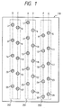
- Fig. 1 shows an exemplary embodiment of a nozzle opening arrangement of an ink jet recording head or the present invention.
- Nozzle plate 130 includes six arrays of nozzle openings A, B, C, D, E, F.
- the nozzle openings 1, 7, 13, 19 and 25 of the first array A are positioned closest to the center line of the nozzle plate 130.
- Nozzle openings 2, 8, 14, 20 and 26 of the second array B are positioned close to one lateral end of the nozzle plate 130, for example, at the left end, and the nozzle openings 3, 9, 15, 21 and 27 of the third array C are positioned between the first array A and the second array B.
- Nozzle openings 4, 10, 16, 22 and 28 of the fourth array D are positioned on a side of the first nozzle opening array A opposite to the side at which the third array is positioned.
- the nozzle openings 5, 11, 17, 23 and 29 of the fifth array E are positioned closest to the lateral end opposite to the lateral end at which the second array B is positioned, for example, the right end.
- the nozzle openings 6, 12, 18, 24 and 30 of the sixth array E are positioned closest to the fifth nozzle opening array E.
- the nozzle opening arrays are divided into three groups.
- the first nozzle opening array A and the fourth nozzle opening array D constitute a first group 201.
- the second and third nozzle opening arrays B and C constitute a second group 202.
- the fifth and sixth nozzle opening arrays E and F constitute a third group 203.
- the nozzle openings of the respective groups 201, 202 and 203 communicate with the ink jet recording head unit, as shown in Figs. 2, 3A and 3B, so that the nozzle openings are supplied with ink to be jetted.
- the nozzle openings 1, 4, 7, 10, 13, 16, 19, 22, 25 and 28 of the first group 201 are arranged at a pitch of three dots apart in an auxiliary scanning direction, that is, in the vertical direction as viewed in Fig. 1.
- the pairs of nozzle openings 2 and 3, 8 and 9, 14 and 15, 20 and 21, and 26 and 27 of the second group 202 are arranged at a pitch of one dot apart, and are positioned in the vertical direction between or substantially between nozzle openings 1 and 4, 7 and 10, 13 and 16, 19 and 22, and 25 and 28, respectively. This pitch is repeated, for example, at a cycle of five pairs of dots.
- the pairs of nozzle openings 5 and 6, 11 and 12, 17 and 18, 23 and 24, and 39 and 30 of the third group 203 are arranged at a pitch of one dot apart, and are positioned in the vertical direction between or substantially between nozzle openings 4 and 7, 10 and 13, 16 and 19, and 22 and 25, and in the vertical direction below or substantially below nozzle opening 28, respectively. This pitch is repeated, for example, at a cycle of five pairs of dots.
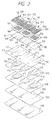
- Fig. 2 is an exploded perspective view showing the assembly of an embodiment of the ink jet recording head of the present invention, as shown in Fig. 1.
- Figs. 3A and 3B are sectional views, each showing a structure in the vicinity of a pressure producing chamber that is connected to a single common ink chamber.
- the ink jet recording head comprises piezoelectric vibration element drive sections 100, which are formed by mounting piezoelectric vibration plates 104, made of PZT or the like, onto a surface of a vibration plate 102 made of a zirconia (ZrO 2 ) thin plate member or the like whose thickness is about 10 ⁇ m.
- the piezoelectric vibrations plates 104 are mounted so as to oppose pressure producing chambers 103, which will be described below.
- a spacer 105 which is made of a ceramic thin plate member, such as a 150 ⁇ m-thick zirconia thin plate member or the like, has through holes 106 therein. These through holes 106 constitute the pressure producing chambers 103, which are thus formed at a predetermined pitch. The shape of each through hole 106 coincides with that of the pressure producing chamber 103.
- a board 108 is disposed adjacent the spacer 105 to close the corresponding ends of the pressure producing chambers 103.
- Introducing holes 109 and 111 are formed in board 108.
- Introducing holes 109 have a larger diameter than that of nozzle openings 131, which are formed in nozzle plate 130, and enable the nozzle openings 131 to communicate with corresponding pressure producing chambers 103.
- Introducing holes 111 enable their corresponding pressure producing chambers 103 to communicate with common ink chamber 110.
- the unit fixing plate 112 also acts as a flow path regulating plate in this embodiment.
- the unit fixing plate 112 includes flow path regulating holes 113, which are positioned between the introducing holes 111 and the common ink chamber 110 when the unit fixing plate 112 is mounted between the board 108 and the thermal deposition film 115, described below, as shown in Fig. 3B. Also, the unit fixing plate 112 includes introducing holes 114 which are positioned to oppose the through holes 109 when the unit fixing plate 112 is mounted to the board 108. Each flow path regulating hole 113 has a flow resistance substantially equal to that of the nozzle opening 131, and each introducing hole 114 enables the nozzle opening 131 to communicate with the pressure producing chamber 103.
- the thermal deposition film 115 bonds a common ink chamber forming plate 118, described below, to the unit fixing plate 112.
- the thermal deposition film 115 includes windows 116 and introducing holes 117. Each window 116 coincides with the common ink chamber 110, and each introducing hole 117 enables the nozzle opening 131 to communicate with the pressure producing chamber 103.
- the common ink chaser forming plate 118 includes windows 120 and introducing holes 121.
- the ink chamber forming plate 118 is, for example, a 150 ⁇ m-thick stainless steel plate member or the like, which is corrosion resistant and whose thickness is adequate to form the common ink chambers 110.
- Each window 120 is substantially V-shaped and thus corresponds to the shape of the common ink chamber 110.
- Each introducing hole 121 has a diameter larger than that of the nozzle openings 131, and enables their corresponding pressure producing chambers 103 to communicate with the nozzle openings 131.
- the nozzle openings 131 are formed in the nozzle plate 130.
- the nozzle plate 130 is fixed to the common ink chamber forming plate 118 by a thermal deposition film 133 or the like, so that the nozzle openings 131 communicate with their respective pressure producing chambers 103 through introducing holes 109, 114, 117 and 121, and through hole 134 formed in the thermal deposition film 133.
- the diameter of those introducing holes 109, 114 and 121 is determined so that the opening at least on the side of the nozzle opening 131 is small.
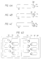
- the laminated structure allows the centers of the introducing holes 109, 114, 117 and 121 to be aligned, to allow the nozzle opening 131 to communicate with the pressure producing chamber 103 as shown in Fig. 3A.
- the ink is not likely to stagnate. Accordingly, air bubbles contained in the ink can be discharged swiftly from the nozzle opening.
- the nozzle openings 131 can be aligned near the end of the pressure producing chamber 103. If the respective introducing holes 109, 114, 121, for example, are sequentially shifted in any direction with respect to the pressure producing chamber 103, as shown in Figs. 4B, 4C, then the pitch between the adjacent nozzle openings 131 can be adjusted arbitrarily.
- the pressure producing chambers 103 may be arranged to communicate with nozzle openings 131 which are positioned asymmetrically on the nozzle plate 130.
- the vibration plate 102 In the recording head when a drive signal is applied to the piezoelectric vibration plates 103, the vibration plate 102 is flexed, thereby causing the pressure producing chambers 103 to contract. As a result, the ink within the pressure producing chambers 103 is jetted to the nozzle openings 131 via the introducing holes 109, 114, 117 and 121, and is jetted therefrom in the form of an ink droplet.
- the piezoelectric vibration plate 104 When the drive signal is removed after the ink droplets have been jetted, the piezoelectric vibration plate 104 returns to its original position, thereby causing the pressure producing chamber 103 to expand to its original size. As a result, an amount of ink corresponding to the amount of ink jetted out of the nozzle openings 131 flows into the pressure producing chamber 103 from the common ink chamber 110 via the flow path regulating holes 113 and the introducing holes 111. This cycle is repeated until the amount of ink droplets necessary for printing have been jetted.
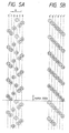
- Fig. 5A is on exemplary diagram illustrating the correspondence between the position of lines printed in a print line (e.g, a single character line) in the horizontal direction and the nozzle openings that print such lines of the print line. This figure also illustrates the position of some of the nozzle openings that print the uppermost lines in an adjacent print line. The number in each circle corresponds to the number assigned to a nozzle opening in Fig. 1.
- Lines in a print line are printed at an interval of three dots by the nozzle openings 1, 4, 7, 10, 13, 16, 19, 22, 25 and 28 of the nozzle opening arrays A and D of the first group 201.
- Two lines are printed by the nozzle openings 2, 3, 8, 9, 14, 15, 20, 21, 26 and 27 of the nozzle opening arrays B and C of the second group 202, so as to supplement lines between the odd-numbered nozzle openings and the even-numbered nozzle openings of the first group 201, i.e., between nozzle openings 1 and 4, 7 and 10, 13 and 16, 19 and 22, and 25 and 28.
- Two lines are similarly printed by the nozzle openings 5, 6, 11, 12, 17, 18, 23, 24, 29 and 30 of the nozzle opening arrays E and F of the third group 203, so as to supplement the lines between the even-numbered nozzle openings and the odd-numbered nozzle openings of the first group 201, which are not supplemented by the second group 202, i.e., between nozzle openings 4 and 7, 10 and 13, 16 and 19, 22 and 25, and vertically below 28.
- the maximum distance in the main scanning direction between any two nozzle openings that print vertically adjacent lines is equal to half or substantially half the distance between groups 202 and 203 arranged on both sides of the nozzle plate 130.
- an error that occurs when the vertical direction of the nozzle openings in the recording head is not parallel with the sheet forward direction, but is slightly at an angle with respect to the carriage is substantially halved. That is, assuming that the distance in the main scanning direction between the nozzle opening arrays 202 and 203 is G, and that the angle of inclination of the head is ⁇ , an error G x sin ⁇ is substantially halved.
- the nozzle openings are arranged so that the uppermost line in a print line is printed by a nozzle opening of the first group 201, that is, nozzle opening 1 in this embodiment, and the lowermost line in a print line is printed by a nozzle opening of either group 202 or 203 (i.e., nozzle opening 30 in this embodiment), the distance in the main scanning direction between the nozzle openings that prints the lowermost line of the print line (i.e., nozzle 30), and the upper most line of the next print line (i.e., nozzle 1), is also equal to half or substantially half the distance between groups 202 and 203. This, in turn, halves or substantially halves the error that may occur between the print lines that are printed before and after sheet forwarding, and thus prevents a white line or a black line from being produced, as often is the case in conventional printers.
- a conventional print head having a nozzle opening arrangement as shown in Fig. 5B adjacent lines printed by the nozzle openings arranged on opposite sides of the print head (e.g., the nozzle openings 6 and 7 of the nozzle opening arrays A' and F') result in a large print error when the direction of the nozzle opening arrays A' through F' is not parallel to the sheet forwarding direction. This error occurs because the distance between these nozzle openings in the main scanning direction is equal to the distance between the nozzle opening arrays A' and F'.
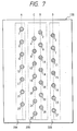
- Fig. 6 shows another embodiment of the nozzle opening arrangement according to the present invention.
- nozzle opening array groups 204, 205 and 206 are formed in a nozzle plate 130.
- the nozzle openings 1, 5, 9, 13, 17, 21 and 25 of the single array A of the first group 204 are arranged at a pitch of four dots apart in the sheet forwarding direction.
- the second group 205 has two nozzle opening arrays B and C, each having nozzle openings spaced at a pitch of two dots from each other.
- the third group 206 has a single nozzle opening array D, wherein the nozzle openings are spaced at a pitch of four dots from each other.
- the nozzle openings of the first and third groups 204 and 206 are arranged on opposite sides of the nozzle plate 130, and are positioned so as to alternately supplement the nozzle openings of the second group 205 arranged in the middle of the nozzle plate 130. That is, in this embodiment, lines printed by the nozzle openings 1, 5, 9, 13, 17, 21 and 25 off the first group 204 and lines printed by the nozzle openings 3, 7, 11, 15, 19, 23 and 27 of the third group 206 are printed so as to interpose lines printed by the nozzle openings 2, 4 ⁇ ⁇ 26, 28 of the second group 205.
- the maximum distance between any two nozzle openings that print vertically adjacent lines is equal to or substantially equal to half the distance between the nozzle opening arrays A and D.
- a nozzle opening of one of the groups 204 and 206 i.e., nozzle opening 1 of group 204 is positioned to print the uppermost line of a print line, and the nozzle opening 28 of group 205 in positioned to print the lowermost line in the print line, the distance between the nozzle openings that print vertically adjacent print lines before and after sheet forwarding is equal or substantially equal to half the maximum distance between nozzle opening arrays 204 and 206.
- this reduces errors that may occur (e.g., white line or black line) between adjacent print lines when the direction of the nozzle opening arrays is not parallel to the sheet feed direction.
- a group 211 having the nozzle openings 2, 4, 6 ⁇ ⁇ 24, 26, 28 arranged at a pitch of two dots apart from each other may be interposed between groups 210 and 212, which alternately supplement this group 211 during printing.
- Group 210 consists of a nozzle opening array A having the nozzle openings 1, 5 ⁇ ⁇ 21, 25, arranged at a pitch of four dots from each other.
- Group 212 consists of a nozzle opening array C having the nozzle openings 3, 7 ⁇ ⁇ 23, 27, arranged at a pitch of four dots from each other.
- nozzle openings When the nozzle openings are linearly arranged at an extremely high density as in nozzle opening array B of the group 211, two arrays of pressure producing chambers 103 and 103' are used, as shown in Fig. 9. These chambers 103 and 103' are arranged so that their adjacent ends are as close as possible to the positions at which their respective nozzle opening is disposed (i.e., as close as possible to line L-L). Also, introducing holes 109, 114, 121, providing communication between the pressure producing chambers 103 and the nozzle openings 131, and introducing holes 109', 114', 121', providing communication between pressure producing chambers 103' and nozzle openings 131', are shifted toward the line L-L.
- the lines printed by the nozzle openings 2, 4, 6 ⁇ ⁇ 24, 26, 28 of the nozzle opening array B are alternately supplemented by the lines printed by the nozzle openings 1, 5, 9 ⁇ ⁇ 21, 25 of the nozzle opening array A and by the nozzle openings 3, 7, 11 ⁇ ⁇ 23, 27 of the nozzle opening array C, arranged at opposite sides of the nozzle plate 130.
- the nozzle opening 1 of group 210 is positioned uppermost, and nozzle opening 28 of group 212 is positioned lowermost, thereby reducing errors that can occur between print lines as discussed in the previous embodiments.
- each ink flow path is formed so as to smoothly connect the introducing holes 109, 114, 121 and the introducing holes 109', 114', 121' that are formed in the respective thin plate members, so as to be tapered toward the nozzle opening. Therefore, the ink is not likely to stagnate, and air bubbles contained in the ink is effectively discharged.
- a nozzle opening of the nozzle opening arrays of groups 205 and 211 positioned in the middle of the nozzle plate 130, is positioned at the lowermost end of the recording head
- similar effects can be provided by alternately positioning a nozzle opening of groups 205 and 211 at the uppermost end of the recording head.
- the nozzle opening array A of group 204 can be shifted down by four dots. That is, nozzle opening 1 can be set to the position of the nozzle opening 5, and printing can be performed done in the order of the currently assigned nozzle opening numbers, i.e., 2, 3, 4, 5, ⁇ ⁇ 27, 28.
- printing can be done starting with the nozzle opening 2 of the nozzle opening array B by either omitting the uppermost nozzle opening 1 of the nozzle opening array A of the group 204 or 210 shown in Fig. 7 and 8, respectively, or by not using nozzle opening 1.
- the number of nozzle openings in the nozzle opening array other than that of the group in the middle is decreased as described above, then the number of nozzle openings of the nozzle opening array A of group 204 in Fig. 7, or of group 210 in Fig. 8, is decreased to 6, thus leaving nozzle opening array A short one nozzle opening compared with group 206 in Fig. 7 or group 212 in Fig. 8.
- This allows the nozzle openings of group 205 or 210 in the middle of the nozzle plate to be positioned uppermost and lowermost.
- the nozzle opening that prints the last line of a print line and the nozzle opening that prints the first line of a next print line belong to the same group, which in turn allows printing quality to be improved.
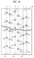
- FIG. 10 shows an embodiment of an ink jet recording head according to the present invention having this type of nozzle opening arrangement.
- This embodiment is suitable for a recording head capable of extremely high-density printing with a particularly great number of nozzle openings, e.g., 64 nozzle openings, formed on a single nozzle plate.
- the nozzle openings of the recording head are arranged at the same pitch as those in the embodiment of Fig. 1 in nozzle opening arrays A and D of group 214 arranged in the middle of the nozzle plate.
- one of the groups at the sides of the nozzle plate has two less nozzle openings.
- nozzle openings 65 and 66 in group 215 arranged on the right side, as shown in Fig. 10, are removed.
- the lowermost line of a print line (e.g., a single row of characters) is printed by nozzle opening 64 in the middle and the uppermost line of a next row is printed by the nozzle opening 1 of group 214 also in the middle. Therefore, not only can inter-line error, as described above, be minimized, but also high quality printing can be implemented in a solid image, such as a graphic image, when printing is done by using a part of the upper side of the recording head when, for example, the last line of such solid image is to be printed, because the nozzle opening 64 that prints the lowermost line of the penultimate row and the nozzle opening 1 that prints the uppermost line of the last row belong to group 214 in the middle of the nozzle plate.
- a solid image such as a graphic image
- an ink jet recording head comprises a plurality of thin plate members 108,112,118 each having a plurality of holes 109, 114, 121 therein, said thin plate members 108,112,118 being laminated together so that said holes 109,114,121 formed in adjacent said thin plate members 108,112,118 are aligned with each other and cooperate to form a plurality of ink flow paths, each continuously extending from a respective nozzle opening 131 to a respective pressure producing chamber 103 which communicates with an ink supply section 110.
- the areas of the holes 109,114,121 of the thin plate members 108,112,118 arranged in succession towards said nozzle openings 131 become sequentially smaller such that the areas of the holes 109,114,121 of the thin plate member 108,112,118 closest to the nozzle openings 131 are smallest and the areas of the holes 109,114,121 of the thin plate members 108,112,118 further away from the nozzle openings 131 are largest.
- the holes 109,114,121 formed in adjacent said thin plate members 108,112,118 are shifted with respect to each other.
- the holes 109,114,121 of the adjacent thin plate members 108,112,118 are sequentially shifted outward with respect to each other in a manner towards said nozzle openings 131 such that the holes 109,114,121 of said thin plate member 108,112,118 closest to the nozzle opening 131 is at a maximum shifted distance with respect to the holes 109,114,121 of the thin plate member 108,112,118 furthest from the nozzle opening 131.
- the ink flow paths, nozzle openings 131 and pressure producing chambers 103 are grouped into ink flow path units, the ink flow path units being arranged so that the nozzle openings of one of said ink flow path units are positioned between the nozzle openings of another one said ink flow path units.
Abstract
Description
- The invention relates to an ink jet recording head having a plurality of nozzle openings disposed in a sheet forwarding direction, with each nozzle opening jetting an ink droplet due to pressure provided by a pressure producing chamber. More particularly, the invention is directed to a nozzle opening arrangement on the ink jet recording head.
- Ink jet recording heads are widely used throughout the printing industry. Such ink jet recording heads exhibit high recording density, are capable of printing dots of various sizes, and are relatively quiet during operation.
- Two basic types of ink jet recording heads exist. A bubble jet type recording head uses thermal energy provided by a heater to effect printing. On the other hand, in a piezoelectric vibration element driven recording head, the displacement of piezoelectric vibration elements causes ink to be emitted to effect printing.
- Two general types of piezoelectric vibration element driven recording heads exist. In the first type, vortical vibration of the piezoelectric vibration elements causes ink to be emitted. In the second type, flexural vibration of the piezoelectric vibration elements causes ink to be emitted.
- In the first type of piezoelectric vibration element driven recording heads, the area in which a piezoelectric vibration element abuts against the vibration plate can be reduced. Hence, the interval between the nozzle opening arrays can easily be made small. However, the process for assembling such a recording head is complicated because each piezoelectric vibration element is extremely small.
- The second type of piezoelectric vibration element driven recording heads employs a laminated structure, such as described in Japanese Unexamined Patant Publication No. 4-366643. That is, a common ink supply section, and pressure producing chambers or ink flow paths, are first formed in each of a plurality of thin plate members. These thin plate members are then sequentially laminated on the back of a nozzle plate. Accordingly, the assembly process is simple.
- However, in this arrangement, each flow path extending from the pressure producing chamber to the nozzle openings is formed by making communicating holes in each thin plate member, and arranging these communicating holes proximate to one another. Hence, it is difficult to discharge the tiny air bubbles in the ink from the corners of the flow paths formed in each thin plate member.
- In addition, in this arrangement, the size of the piezoelectric vibration plate mounted on the pressure producing chamber is larger than that of the piezoelectric vibration plate used as the piezoelectric vibration element in the first type of piezoelectric vibration element driven recording head. Hence, the distance between the nozzle opening arrays is increased.
- If the distance between the nozzle opening arrays is increased, error between dots printed on a recording sheet in the auxiliary scanning direction tends to increase if three or more nozzle opening arrays are formed in an attempt to improve printing quality. In this case, however, printing quality is actually reduced.
- That is, a recording head having a plurality of nozzle opening arrays is designed so that each nozzle opening array enables a dot to be printed at a predetermined position in the auxiliary scanning direction. As a result, this type of recording head has the uppermost nozzle opening and the lowermost nozzle opening arranged at opposite ends in the main scanning direction. This causes an error of


- An ink jet recording head designed to eliminate this problem is described in European Laid-Open Patent Publication No. 554907 herewith incorporated by reference. In this ink jet recording head, four nozzle opening arrays, each having a plurality of nozzle openings linearly pitched in the sheet forwarding direction at an interval corresponding to the number of nozzle opening arrays, have their positions in the main scanning direction staggered by a predetermined interval so as to be different from the physically arranged sequence thereof. This arrangement, which reduces the distance in the auxiliary scanning direction between the uppermost nozzle opening and the lowermost nozzle opening of the recording head, can prevent printing of white lines and black lines due to displacement in the angle θ between the nozzle opening array and the sheet forwarding direction.
- However, this advantage is realized only when the number of nozzle opening arrays is four. Hence, such a design is applicable to a limited number of recording heads.
- In view of the above problems associated with conventional ink jet recording heads, an improved ink jet recording head according to the
independent claim 1 is provided. Further advantageous features, details and aspects of the invention are evident from the dependent claims, the description and the drawings. The claims are intended to be understood as a first non-limiting approach of defining the invention in general terms. An aspect of the present invention is to provide a laminated type ink jet recording head which minimizes stagnation of air bubbles in its ink flow paths. - An ink jet recording head is formed by laminating a plurality of thin plate members having a plurality of ink flow paths partially formed therein. Each ink flow path extends continuously so as to reach a nozzle opening from an ink supply section via a pressure producing chamber. In such ink jet recording head, communicating holes formed in the respective thin plate members to enable the pressure producing chamber to communicate with the nozzle opening are linearly arranged. As a result of this construction, the ink from the pressure producing chamber can flow without stagnating in the communicating holes in the thin plate members, so that the air bubbles in the ink can be discharged from the nozzle openings effectively.
- An aspect of the invention is to provide an ink jet recording head which can be employed in a recording head having a plurality of nozzle opening arrays, preferably three or more, and which can minimize inter-line distance error to ensure high-quality printing.
- To achieve the above aspects , the invention provides an ink jet recording head having a plurality of nozzle openings arrays, arranged in an auxiliary scanning direction, which is substantially perpendicular to the main scanning direction. The nozzle opening arrays are divided into groups, preferably three groups, and spaced at predetermined intervals in the main scanning direction.
- In such ink jet recording head, nozzle openings of the groups arranged on both sides of a group arranged in the middle of the recording head supplement spaces between these nozzle openings of the middle array. Furthermore, a nozzle opening of the group arranged in the middle is positioned uppermost or lowermost on the face of the print head, so that lines printed by the nozzle openings of the groups arranged on both sides interpose the lines printed by the nozzle openings of the middle group. As a result, the maximum distance between nozzle openings printing adjacent lines in the main scanning direction can be equal or substantially equal to half the maximum distance between the nozzle opening arrays at both sides of the print head. Therefore, inter-line positional error is reduced.
- These and other objects and advantages of the invention will become more apparent and more readily appreciated from the following detailed description of the presently preferred exemplary embodiments of the invention taken in conjunction with the accompanying drawings, of which:
- Fig. 1 illustrates an embodiment of the nozzle opening arrays of an ink jet recording head of the present invention;
- Fig. 2 is an exploded perspective view showing the detailed assembly of the ink jet recording head at Fig. 1;
- Fig. 3A is a sectional view showing the ink jet recording head of Fig. 1;
- Fig. 3B is a sectional view showing another ink jet recording head with the position of a nozzle opening shifted;
- Figs. 4A to 4D respectively show ink jet recording heads wherein the position of a nozzle opening with respect to the corresponding pressure producing chamber is shifted by adjusting both the position of the nozzle opening and the positions of introducing holes connecting the nozzle opening to the pressure producing chamber in the embodiment of the ink jet recording head shown in Fig. 1;
- Fig. 5A illustrates a pattern printed by a recording head having nozzle opening arrays according to the present invention;
- Fig. 5B illustrates a pattern printed by a recording head having nozzle opening arrays according to a conventional arrangement;
- Fig. 6 illustrates another embodiment of the nozzle opening arrays of an ink jet recording head of the present invention;
- Fig. 7 illustrates a further embodiment of the nozzle opening arrays of an ink jet recording head of the present invention;
- Fig. 8 illustrates a further embodiment of the nozzle opening arrays of an ink jet recording head of the present invention;
- Fig. 9 illustrates an exemplary arrangement of introducing holes for implementing the pitch at which the nozzle openings are positioned as shown in the embodiment or Fig. 8; and
- Fig. 10 illustrates a further embodiment of the nozzle opening arrays of an ink jet recording head of the present invention.
- Fig. 1 shows an exemplary embodiment of a nozzle opening arrangement of an ink jet recording head or the present invention.
Nozzle plate 130 includes six arrays of nozzle openings A, B, C, D, E, F. Thenozzle openings nozzle plate 130.Nozzle openings nozzle plate 130, for example, at the left end, and thenozzle openings -
Nozzle openings nozzle openings nozzle openings - These nozzle opening arrays are divided into three groups. The first nozzle opening array A and the fourth nozzle opening array D constitute a
first group 201. The second and third nozzle opening arrays B and C constitute asecond group 202. The fifth and sixth nozzle opening arrays E and F constitute athird group 203. The nozzle openings of therespective groups - The
nozzle openings first group 201 are arranged at a pitch of three dots apart in an auxiliary scanning direction, that is, in the vertical direction as viewed in Fig. 1. The pairs ofnozzle openings second group 202 are arranged at a pitch of one dot apart, and are positioned in the vertical direction between or substantially betweennozzle openings - The pairs of
nozzle openings third group 203 are arranged at a pitch of one dot apart, and are positioned in the vertical direction between or substantially betweennozzle openings nozzle opening 28, respectively. This pitch is repeated, for example, at a cycle of five pairs of dots. - Fig. 2 is an exploded perspective view showing the assembly of an embodiment of the ink jet recording head of the present invention, as shown in Fig. 1. Figs. 3A and 3B are sectional views, each showing a structure in the vicinity of a pressure producing chamber that is connected to a single common ink chamber.
- As showing in Fig. 2, the ink jet recording head comprises piezoelectric vibration
element drive sections 100, which are formed by mountingpiezoelectric vibration plates 104, made of PZT or the like, onto a surface of avibration plate 102 made of a zirconia (ZrO2) thin plate member or the like whose thickness is about 10 µm. Thepiezoelectric vibrations plates 104 are mounted so as to opposepressure producing chambers 103, which will be described below. - A
spacer 105, which is made of a ceramic thin plate member, such as a 150 µm-thick zirconia thin plate member or the like, has throughholes 106 therein. These throughholes 106 constitute thepressure producing chambers 103, which are thus formed at a predetermined pitch. The shape of each throughhole 106 coincides with that of thepressure producing chamber 103. - A
board 108 is disposed adjacent thespacer 105 to close the corresponding ends of thepressure producing chambers 103. Introducingholes board 108. Introducingholes 109 have a larger diameter than that ofnozzle openings 131, which are formed innozzle plate 130, and enable thenozzle openings 131 to communicate with correspondingpressure producing chambers 103. Introducingholes 111, on the other hand, enable their correspondingpressure producing chambers 103 to communicate withcommon ink chamber 110. - These three
members unit fixing plate 112 by adhesive or the like. Theunit fixing plate 112 also acts as a flow path regulating plate in this embodiment. - The
unit fixing plate 112 includes flowpath regulating holes 113, which are positioned between the introducingholes 111 and thecommon ink chamber 110 when theunit fixing plate 112 is mounted between theboard 108 and thethermal deposition film 115, described below, as shown in Fig. 3B. Also, theunit fixing plate 112 includes introducingholes 114 which are positioned to oppose the throughholes 109 when theunit fixing plate 112 is mounted to theboard 108. Each flowpath regulating hole 113 has a flow resistance substantially equal to that of thenozzle opening 131, and each introducinghole 114 enables thenozzle opening 131 to communicate with thepressure producing chamber 103. - The
thermal deposition film 115 bonds a common inkchamber forming plate 118, described below, to theunit fixing plate 112. Thethermal deposition film 115 includeswindows 116 and introducingholes 117. Eachwindow 116 coincides with thecommon ink chamber 110, and each introducinghole 117 enables thenozzle opening 131 to communicate with thepressure producing chamber 103. - The common ink
chaser forming plate 118 includeswindows 120 and introducingholes 121. The inkchamber forming plate 118 is, for example, a 150 µm-thick stainless steel plate member or the like, which is corrosion resistant and whose thickness is adequate to form thecommon ink chambers 110. Eachwindow 120 is substantially V-shaped and thus corresponds to the shape of thecommon ink chamber 110. Each introducinghole 121 has a diameter larger than that of thenozzle openings 131, and enables their correspondingpressure producing chambers 103 to communicate with thenozzle openings 131. - As described above, the
nozzle openings 131 are formed in thenozzle plate 130. Thenozzle plate 130 is fixed to the common inkchamber forming plate 118 by athermal deposition film 133 or the like, so that thenozzle openings 131 communicate with their respectivepressure producing chambers 103 through introducingholes hole 134 formed in thethermal deposition film 133. The diameter of those introducingholes nozzle opening 131 is small. - Accordingly, the laminated structure allows the centers of the introducing
holes nozzle opening 131 to communicate with thepressure producing chamber 103 as shown in Fig. 3A. Hence, even if thenozzle opening 131 is shifted by a distance ΔL, as shown in Fig. 3B, the ink is not likely to stagnate. Accordingly, air bubbles contained in the ink can be discharged swiftly from the nozzle opening. - That is, if the
nozzle openings 131 are shifted in a direction toward one end of thepressure producing chamber 103 as shown in Fig. 4A, thenozzle opening 131 can be aligned near the end of thepressure producing chamber 103. If the respective introducingholes pressure producing chamber 103, as shown in Figs. 4B, 4C, then the pitch between theadjacent nozzle openings 131 can be adjusted arbitrarily. - Alternatively, as shown in Fig. 4D, the
pressure producing chambers 103 may be arranged to communicate withnozzle openings 131 which are positioned asymmetrically on thenozzle plate 130. - In the recording head when a drive signal is applied to the
piezoelectric vibration plates 103, thevibration plate 102 is flexed, thereby causing thepressure producing chambers 103 to contract. As a result, the ink within thepressure producing chambers 103 is jetted to thenozzle openings 131 via the introducingholes - When the drive signal is removed after the ink droplets have been jetted, the
piezoelectric vibration plate 104 returns to its original position, thereby causing thepressure producing chamber 103 to expand to its original size. As a result, an amount of ink corresponding to the amount of ink jetted out of thenozzle openings 131 flows into thepressure producing chamber 103 from thecommon ink chamber 110 via the flowpath regulating holes 113 and the introducingholes 111. This cycle is repeated until the amount of ink droplets necessary for printing have been jetted. - Operation of this embodiment of the recording head having the nozzle opening arrangement of the embodiment shown in Fig. 1 will now be described with reference to Fig. 5A.
- Fig. 5A is on exemplary diagram illustrating the correspondence between the position of lines printed in a print line (e.g, a single character line) in the horizontal direction and the nozzle openings that print such lines of the print line. This figure also illustrates the position of some of the nozzle openings that print the uppermost lines in an adjacent print line. The number in each circle corresponds to the number assigned to a nozzle opening in Fig. 1.
- Lines in a print line are printed at an interval of three dots by the
nozzle openings first group 201. Two lines are printed by thenozzle openings second group 202, so as to supplement lines between the odd-numbered nozzle openings and the even-numbered nozzle openings of thefirst group 201, i.e., betweennozzle openings - Two lines are similarly printed by the
nozzle openings third group 203, so as to supplement the lines between the even-numbered nozzle openings and the odd-numbered nozzle openings of thefirst group 201, which are not supplemented by thesecond group 202, i.e., betweennozzle openings - With the nozzle openings of the second and
third groups nozzle plate 130 to print lines which interpose the lines printed by the nozzle openings of thefirst group 201, arranged in the middle of the nozzle plate, the maximum distance in the main scanning direction between any two nozzle openings that print vertically adjacent lines is equal to half or substantially half the distance betweengroups nozzle plate 130. For this reason, an error that occurs when the vertical direction of the nozzle openings in the recording head is not parallel with the sheet forward direction, but is slightly at an angle with respect to the carriage, is substantially halved. That is, assuming that the distance in the main scanning direction between thenozzle opening arrays 
- In addition, since the nozzle openings are arranged so that the uppermost line in a print line is printed by a nozzle opening of the
first group 201, that is,nozzle opening 1 in this embodiment, and the lowermost line in a print line is printed by a nozzle opening of eithergroup 202 or 203 (i.e., nozzle opening 30 in this embodiment), the distance in the main scanning direction between the nozzle openings that prints the lowermost line of the print line (i.e., nozzle 30), and the upper most line of the next print line (i.e., nozzle 1), is also equal to half or substantially half the distance betweengroups - That is, in a conventional print head having a nozzle opening arrangement as shown in Fig. 5B, adjacent lines printed by the nozzle openings arranged on opposite sides of the print head (e.g., the
nozzle openings - In addition, because this large distance in the main scanning direction exists between
nozzle openings - Fig. 6 shows another embodiment of the nozzle opening arrangement according to the present invention. In a manner similar to the embodiment shown in Fig. 1, nozzle
opening array groups nozzle plate 130. Thenozzle openings first group 204 are arranged at a pitch of four dots apart in the sheet forwarding direction. - The
second group 205 has two nozzle opening arrays B and C, each having nozzle openings spaced at a pitch of two dots from each other. Thethird group 206 has a single nozzle opening array D, wherein the nozzle openings are spaced at a pitch of four dots from each other. - The nozzle openings of the first and
third groups nozzle plate 130, and are positioned so as to alternately supplement the nozzle openings of thesecond group 205 arranged in the middle of thenozzle plate 130. That is, in this embodiment, lines printed by thenozzle openings first group 204 and lines printed by thenozzle openings third group 206 are printed so as to interpose lines printed by thenozzle openings second group 205. - Therefore, the maximum distance between any two nozzle openings that print vertically adjacent lines is equal to or substantially equal to half the distance between the nozzle opening arrays A and D. In addition, since a nozzle opening of one of the
groups 204 and 206 (i.e.,nozzle opening 1 of group 204) is positioned to print the uppermost line of a print line, and thenozzle opening 28 ofgroup 205 in positioned to print the lowermost line in the print line, the distance between the nozzle openings that print vertically adjacent print lines before and after sheet forwarding is equal or substantially equal to half the maximum distance betweennozzle opening arrays - It is apparent that similar advantageous effects can be obtained by reversing the arrangement of the two nozzle opening arrays B and C of the
second group 205, as shown in Fig. 7. - As shown in Fig. 8, a
group 211 having thenozzle openings groups group 211 during printing.Group 210 consists of a nozzle opening array A having thenozzle openings Group 212, on the other hand, consists of a nozzle opening array C having thenozzle openings - When the nozzle openings are linearly arranged at an extremely high density as in nozzle opening array B of the
group 211, two arrays ofpressure producing chambers chambers holes pressure producing chambers 103 and thenozzle openings 131, and introducing holes 109', 114', 121', providing communication betweenpressure producing chambers 103' and nozzle openings 131', are shifted toward the line L-L. - Also in this embodiment, as in the aforementioned embodiment, the lines printed by the
nozzle openings nozzle openings nozzle openings nozzle plate 130. Furthermore, thenozzle opening 1 ofgroup 210 is positioned uppermost, and nozzle opening 28 ofgroup 212 is positioned lowermost, thereby reducing errors that can occur between print lines as discussed in the previous embodiments. - Furthermore, each ink flow path is formed so as to smoothly connect the introducing
holes - While in the embodiments shown in Figs. 6, 7, and 8, a nozzle opening of the nozzle opening arrays of
groups nozzle plate 130, is positioned at the lowermost end of the recording head, it is apparent that similar effects can be provided by alternately positioning a nozzle opening ofgroups group 204 can be shifted down by four dots. That is,nozzle opening 1 can be set to the position of thenozzle opening 5, and printing can be performed done in the order of the currently assigned nozzle opening numbers, i.e., 2, 3, 4, 5, ·· ·· 27, 28. - Further, with respect to the embodiments shown in Figs. 7 and 8, it is apparent that printing can be done starting with the
nozzle opening 2 of the nozzle opening array B by either omitting theuppermost nozzle opening 1 of the nozzle opening array A of thegroup nozzle opening 1. - If the number of nozzle openings in the nozzle opening array other than that of the group in the middle is decreased as described above, then the number of nozzle openings of the nozzle opening array A of
group 204 in Fig. 7, or ofgroup 210 in Fig. 8, is decreased to 6, thus leaving nozzle opening array A short one nozzle opening compared withgroup 206 in Fig. 7 orgroup 212 in Fig. 8. This, in turn, allows the nozzle openings ofgroup - The nozzle openings of the recording head (from the
uppermost nozzle opening 1 to the lowermost nozzle opening 64) are arranged at the same pitch as those in the embodiment of Fig. 1 in nozzle opening arrays A and D ofgroup 214 arranged in the middle of the nozzle plate. As a result of this arrangement, one of the groups at the sides of the nozzle plate has two less nozzle openings. For example,nozzle openings group 215 arranged on the right side, as shown in Fig. 10, are removed. - According to this embodiment, the lowermost line of a print line (e.g., a single row of characters) is printed by nozzle opening 64 in the middle and the uppermost line of a next row is printed by the
nozzle opening 1 ofgroup 214 also in the middle. Therefore, not only can inter-line error, as described above, be minimized, but also high quality printing can be implemented in a solid image, such as a graphic image, when printing is done by using a part of the upper side of the recording head when, for example, the last line of such solid image is to be printed, because thenozzle opening 64 that prints the lowermost line of the penultimate row and thenozzle opening 1 that prints the uppermost line of the last row belong togroup 214 in the middle of the nozzle plate. - While a single group consists of one or two nozzle opening arrays in the aforementioned embodiments, it is apparent that similar effects can be obtained by putting three or more nozzle opening arrays in a single group. Further, while a recording head utilizing flexural vibration is described in the above embodiments, it is apparent that similar effects and advantages can be obtained by employing a piezoelectric vibration element of the vertical mode, in which the distance between nozzle opening arrays can be made relatively small.
- According to a further aspect of the invention, an ink jet recording head comprises a plurality of thin plate members 108,112,118 each having a plurality of
holes pressure producing chamber 103 which communicates with anink supply section 110. The areas of the holes 109,114,121 of the thin plate members 108,112,118 arranged in succession towards saidnozzle openings 131 become sequentially smaller such that the areas of the holes 109,114,121 of the thin plate member 108,112,118 closest to thenozzle openings 131 are smallest and the areas of the holes 109,114,121 of the thin plate members 108,112,118 further away from thenozzle openings 131 are largest. The holes 109,114,121 formed in adjacent said thin plate members 108,112,118 are shifted with respect to each other. To be more specific, the holes 109,114,121 of the adjacent thin plate members 108,112,118 are sequentially shifted outward with respect to each other in a manner towards saidnozzle openings 131 such that the holes 109,114,121 of said thin plate member 108,112,118 closest to thenozzle opening 131 is at a maximum shifted distance with respect to the holes 109,114,121 of the thin plate member 108,112,118 furthest from thenozzle opening 131. The ink flow paths,nozzle openings 131 andpressure producing chambers 103 are grouped into ink flow path units, the ink flow path units being arranged so that the nozzle openings of one of said ink flow path units are positioned between the nozzle openings of another one said ink flow path units.
Claims (5)
- An ink jet recording head comprising:a board (130) having a plurality of nozzle openings (131) therein arranged in nozzle opening arrays (A,B,C, D,E,F) formed in an auxiliary scanning direction, the nozzle opening arrays (A,B,C,D,E,F) being divided into groups, preferably three groups (201,202,203;204,205, 206;210,211,212;213,214,215) at a predetermined interval in a main scanning direction, said nozzle openings (131) of groups (202,203;204,206;210,212;213,215) arranged at both sides of a group (201;205,211;214) arranged in the middle in the main scanning direction of the ink jet recording head being positioned vertically between adjacent nozzle openings (131) of the middle group (201;205;211;214); and a nozzle opening (131) of the middle groups (201;205;211;214) positioned uppermost and/or lowermost in the auxiliary scanning direction, so that lines printed by the nozzle openings (131) of the groups (202,203;204,206;210,212;213,215) arranged at both sides interpose lines printed by the nozzle openings of the middle group (201;205;211;214).
- An ink jet recording head according to claim 1,
characterized in that each group (201,202,203;204,205, 206;210,211,212;213,214,215) has two nozzle opening arrays (A,B,C,D,E,F), the nozzle openings (131) of the middle group (201;205;211;214) being pitched at an interval of three dots in the auxiliary scanning direction, pairs of nozzle openings (131) of the groups (202,203; 204,206;210,212;213,215) arranged on both sides are pitched at an interval of one dot, and said pairs are arranged at an interval of five dots so as to be positioned vertically between said nozzle openings (131) of the middle group (201;205;211;214). - An ink jet recording head according to claim 1,
characterized in that the nozzle openings (131) of the middle group (201;205;211;214) are pitched at an interval of two dots, each of the groups (202,203;204,206; 210,212;213,215) arranged on both sides has a single nozzle opening array having its nozzle openings pitched at an interval of four dots so as to be vertically between the nozzle openings of the middle group (201;205; 211;214). - An ink jet recording head according to claim 3,
characterized in that the middle group (201;205;211;214) has two nozzle opening arrays. - An ink jet recording head according to claim 3,
characterized in that the middle group (201;205;211;214) has a single nozzle opening array.
Applications Claiming Priority (7)
| Application Number | Priority Date | Filing Date | Title |
|---|---|---|---|
| JP35168793A JP3623249B2 (en) | 1993-12-28 | 1993-12-28 | Recording head for inkjet printer |
| JP351687/93 | 1993-12-28 | ||
| JP35168793 | 1993-12-28 | ||
| JP200119/94 | 1994-08-02 | ||
| JP20011994 | 1994-08-02 | ||
| JP6200119A JPH0839798A (en) | 1994-08-02 | 1994-08-02 | Ink-jet recording head |
| EP94120852A EP0661156B1 (en) | 1993-12-28 | 1994-12-28 | Ink jet recording head |
Related Parent Applications (2)
| Application Number | Title | Priority Date | Filing Date |
|---|---|---|---|
| EP94120852.2 Division | 1994-12-28 | ||
| EP94120852A Division EP0661156B1 (en) | 1993-12-28 | 1994-12-28 | Ink jet recording head |
Publications (3)
| Publication Number | Publication Date |
|---|---|
| EP0812692A2 true EP0812692A2 (en) | 1997-12-17 |
| EP0812692A3 EP0812692A3 (en) | 1998-01-07 |
| EP0812692B1 EP0812692B1 (en) | 2001-11-07 |
Family
ID=26511982
Family Applications (2)
| Application Number | Title | Priority Date | Filing Date |
|---|---|---|---|
| EP94120852A Expired - Lifetime EP0661156B1 (en) | 1993-12-28 | 1994-12-28 | Ink jet recording head |
| EP97116382A Expired - Lifetime EP0812692B1 (en) | 1993-12-28 | 1994-12-28 | Ink jet recording head |
Family Applications Before (1)
| Application Number | Title | Priority Date | Filing Date |
|---|---|---|---|
| EP94120852A Expired - Lifetime EP0661156B1 (en) | 1993-12-28 | 1994-12-28 | Ink jet recording head |
Country Status (5)
| Country | Link |
|---|---|
| US (2) | US5880756A (en) |
| EP (2) | EP0661156B1 (en) |
| DE (2) | DE69423593T2 (en) |
| HK (1) | HK1004809A1 (en) |
| SG (1) | SG64335A1 (en) |
Cited By (1)
| Publication number | Priority date | Publication date | Assignee | Title |
|---|---|---|---|---|
| US7168786B2 (en) | 2003-11-26 | 2007-01-30 | Seiko Epson Corporation | Ink-jetting recording apparatus and liquid ejecting apparatus |
Families Citing this family (33)
| Publication number | Priority date | Publication date | Assignee | Title |
|---|---|---|---|---|
| EP1170127B1 (en) * | 1993-12-24 | 2005-10-19 | Seiko Epson Corporation | Ink jet recording head |
| JP3452111B2 (en) * | 1995-11-10 | 2003-09-29 | セイコーエプソン株式会社 | Ink jet recording head |
| US5757400A (en) * | 1996-02-01 | 1998-05-26 | Spectra, Inc. | High resolution matrix ink jet arrangement |
| US6357855B1 (en) * | 1996-09-27 | 2002-03-19 | 3D Systems, Inc. | Non-linear printhead assembly |
| US6575558B1 (en) * | 1999-03-26 | 2003-06-10 | Spectra, Inc. | Single-pass inkjet printing |
| US6592204B1 (en) * | 1999-03-26 | 2003-07-15 | Spectra, Inc. | Single-pass inkjet printing |
| IL131830A0 (en) * | 1999-09-09 | 2001-03-19 | Scitex Corp Ltd | Print head arrangement |
| US6513905B2 (en) * | 2000-03-31 | 2003-02-04 | Encad, Inc. | Nozzle cross talk reduction in an ink jet printer |
| US6471317B2 (en) * | 2000-04-11 | 2002-10-29 | Seiko Epson Corporation | Liquid jetting apparatus |
| US6305774B1 (en) * | 2000-04-13 | 2001-10-23 | Hewlett-Packard Company | Printhead substrate having an ink jet primitive structure that spans both edges of an ink feed channel |
| US6315389B1 (en) * | 2000-04-13 | 2001-11-13 | Hewlett-Packard Company | Printhead having different center to center spacings between rows of nozzles |
| US6267468B1 (en) * | 2000-04-13 | 2001-07-31 | Hewlett-Packard Company | Printhead substrate having a mixture of single and double sided elongate ink feed channels |
| US6585352B1 (en) * | 2000-08-16 | 2003-07-01 | Hewlett-Packard Development Company, L.P. | Compact high-performance, high-density ink jet printhead |
| US7189344B2 (en) * | 2001-03-12 | 2007-03-13 | Ivoclar Vivadent Ag | Method for producing a synthetic material part |
| DE10111704B4 (en) * | 2001-03-12 | 2008-06-12 | Ivoclar Vivadent Ag | Process for producing a plastic part |
| US6447097B1 (en) * | 2001-04-05 | 2002-09-10 | Xerox Corporation | Row scrambling in ejector arrays |
| US6764163B2 (en) * | 2002-05-31 | 2004-07-20 | Lexmark International, Inc. | Heater configuration for tri-color heater chip |
| US7311380B2 (en) * | 2002-09-26 | 2007-12-25 | Brother Kogyo Kabushiki Kaisha | Inkjet head |
| US6779861B2 (en) * | 2002-12-16 | 2004-08-24 | Xerox Corporation | Enhanced dot resolution for inkjet printing |
| US20050206679A1 (en) * | 2003-07-03 | 2005-09-22 | Rio Rivas | Fluid ejection assembly |
| US6890067B2 (en) * | 2003-07-03 | 2005-05-10 | Hewlett-Packard Development Company, L.P. | Fluid ejection assembly |
| KR20060132541A (en) * | 2003-08-04 | 2006-12-21 | 브리스톨-마이어스 스큅 컴퍼니 | Methods for treating cardiovascular disease using a soluble ctla4 molecule |
| JP2005199696A (en) * | 2003-12-15 | 2005-07-28 | Canon Inc | Ink-jet recording device, ink-jet recording method and recording head |
| GB0414867D0 (en) * | 2004-07-02 | 2004-08-04 | Xaar Technology Ltd | Droplet deposition apparatus |
| US7201476B2 (en) * | 2004-12-10 | 2007-04-10 | Lexmark International, Inc. | Inkjet printhead with bubble handling properties |
| US7540593B2 (en) * | 2005-04-26 | 2009-06-02 | Hewlett-Packard Development Company, L.P. | Fluid ejection assembly |
| US7380914B2 (en) * | 2005-04-26 | 2008-06-03 | Hewlett-Packard Development Company, L.P. | Fluid ejection assembly |
| US7735979B2 (en) * | 2005-07-29 | 2010-06-15 | Brother Kogyo Kabushiki Kaisha | Ink-jet printer and head for the same |
| JP2007076168A (en) * | 2005-09-14 | 2007-03-29 | Fujifilm Corp | Liquid ejection head and image forming device |
| JP2010184440A (en) * | 2009-02-12 | 2010-08-26 | Seiko Epson Corp | Printing method |
| US8419170B2 (en) | 2010-08-05 | 2013-04-16 | Xerox Corporation | Scalable inkjet printhead architecture and method of manufacture |
| JP5720192B2 (en) * | 2010-11-16 | 2015-05-20 | セイコーエプソン株式会社 | Printing device |
| JP5969589B2 (en) | 2012-08-30 | 2016-08-17 | 京セラ株式会社 | Liquid discharge head and recording apparatus using the same |
Citations (3)
| Publication number | Priority date | Publication date | Assignee | Title |
|---|---|---|---|---|
| DE3208104A1 (en) * | 1982-03-06 | 1983-09-08 | Philips Patentverwaltung Gmbh, 2000 Hamburg | Printing head for a matrix printer |
| EP0554907A2 (en) * | 1992-02-07 | 1993-08-11 | Seiko Epson Corporation | Ink jet recording head |
| EP0572231A2 (en) * | 1992-05-27 | 1993-12-01 | Ngk Insulators, Ltd. | Ink jet print head |
Family Cites Families (41)
| Publication number | Priority date | Publication date | Assignee | Title |
|---|---|---|---|---|
| US3946398A (en) * | 1970-06-29 | 1976-03-23 | Silonics, Inc. | Method and apparatus for recording with writing fluids and drop projection means therefor |
| SE349676B (en) * | 1971-01-11 | 1972-10-02 | N Stemme | |
| US4014029A (en) * | 1975-12-31 | 1977-03-22 | International Business Machines Corporation | Staggered nozzle array |
| JPS57113075A (en) * | 1980-12-30 | 1982-07-14 | Fujitsu Ltd | Ink jet head |
| JPS58116163A (en) * | 1981-12-29 | 1983-07-11 | Canon Inc | Liquid injection head |
| DE3331488A1 (en) * | 1982-09-01 | 1984-03-01 | Konishiroku Photo Industry Co., Ltd., Tokyo | HEAD PIECE FOR A PAINT SPRAY PRINTING DEVICE |
| JPS60232967A (en) * | 1984-05-04 | 1985-11-19 | Nec Corp | Ink jet head |
| JPS6119367A (en) | 1984-07-05 | 1986-01-28 | Canon Inc | Liquid injection recording head |
| JPS6192863A (en) * | 1984-10-13 | 1986-05-10 | Fujitsu Ltd | Ink jet head |
| JPS62101455A (en) * | 1985-10-29 | 1987-05-11 | Nec Corp | Ink jet head and its manufacture |
| US4766671A (en) * | 1985-10-29 | 1988-08-30 | Nec Corporation | Method of manufacturing ceramic electronic device |
| US4730197A (en) * | 1985-11-06 | 1988-03-08 | Pitney Bowes Inc. | Impulse ink jet system |
| US4680595A (en) * | 1985-11-06 | 1987-07-14 | Pitney Bowes Inc. | Impulse ink jet print head and method of making same |
| US5258774A (en) | 1985-11-26 | 1993-11-02 | Dataproducts Corporation | Compensation for aerodynamic influences in ink jet apparatuses having ink jet chambers utilizing a plurality of orifices |
| JPS62213399A (en) * | 1986-03-12 | 1987-09-19 | Omron Tateisi Electronics Co | Piezoelectric ceramic unit |
| DE3717294C2 (en) * | 1986-06-10 | 1995-01-26 | Seiko Epson Corp | Ink jet recording head |
| US4695854A (en) * | 1986-07-30 | 1987-09-22 | Pitney Bowes Inc. | External manifold for ink jet array |
| DE3628346A1 (en) * | 1986-08-21 | 1988-02-25 | Siemens Ag | Ink jet print had in thick-layer technology |
| JPS63149159A (en) * | 1986-12-12 | 1988-06-21 | Fuji Electric Co Ltd | Ink jet recording head |
| US4855752A (en) * | 1987-06-01 | 1989-08-08 | Hewlett-Packard Company | Method of improving dot-on-dot graphics area-fill using an ink-jet device |
| JP2806386B2 (en) * | 1988-02-16 | 1998-09-30 | 富士電機株式会社 | Inkjet recording head |
| BR8905585A (en) * | 1988-02-22 | 1990-11-20 | Spectra Inc | PRESSURE CAMERA FOR INK JET SYSTEM |
| JPH0733087B2 (en) * | 1989-06-09 | 1995-04-12 | シャープ株式会社 | Inkjet printer |
| US4950694A (en) * | 1989-06-29 | 1990-08-21 | Union Carbide Chemicals And Plastics Company Inc. | Preparation of polyurethane foams without using inert blowing agents |
| JP2842448B2 (en) * | 1989-07-11 | 1999-01-06 | 日本碍子株式会社 | Piezoelectric / electrostrictive film type actuator |
| US5087930A (en) * | 1989-11-01 | 1992-02-11 | Tektronix, Inc. | Drop-on-demand ink jet print head |
| JP3041952B2 (en) * | 1990-02-23 | 2000-05-15 | セイコーエプソン株式会社 | Ink jet recording head, piezoelectric vibrator, and method of manufacturing these |
| JPH07108102B2 (en) * | 1990-05-01 | 1995-11-15 | 日本碍子株式会社 | Method for manufacturing piezoelectric / electrostrictive film type actuator |
| EP0485241B1 (en) * | 1990-11-09 | 1997-03-12 | Citizen Watch Co., Ltd. | Ink jet head |
| EP0486256B1 (en) * | 1990-11-13 | 1997-08-13 | Citizen Watch Co., Ltd. | Printing head for ink-jet printer |
| JP3089765B2 (en) * | 1991-11-27 | 2000-09-18 | セイコーエプソン株式会社 | Inkjet recording head |
| GB2263943B (en) * | 1992-01-29 | 1996-05-08 | Hunter Fan Co | Ceiling fan |
| JP3171213B2 (en) * | 1992-03-18 | 2001-05-28 | セイコーエプソン株式会社 | Inkjet print head |
| JP3317308B2 (en) * | 1992-08-26 | 2002-08-26 | セイコーエプソン株式会社 | Laminated ink jet recording head and method of manufacturing the same |
| JP3144949B2 (en) * | 1992-05-27 | 2001-03-12 | 日本碍子株式会社 | Piezoelectric / electrostrictive actuator |
| JP3212382B2 (en) * | 1992-10-01 | 2001-09-25 | 日本碍子株式会社 | Precision brazing method |
| JP3106026B2 (en) * | 1993-02-23 | 2000-11-06 | 日本碍子株式会社 | Piezoelectric / electrostrictive actuator |
| US5610645A (en) * | 1993-04-30 | 1997-03-11 | Tektronix, Inc. | Ink jet head with channel filter |
| US5489930A (en) | 1993-04-30 | 1996-02-06 | Tektronix, Inc. | Ink jet head with internal filter |
| US5790149A (en) * | 1993-06-03 | 1998-08-04 | Seiko Epson Corporation | Ink jet recording head |
| US5689291A (en) * | 1993-07-30 | 1997-11-18 | Tektronix, Inc. | Method and apparatus for producing dot size modulated ink jet printing |
-
1994
- 1994-12-28 EP EP94120852A patent/EP0661156B1/en not_active Expired - Lifetime
- 1994-12-28 DE DE69423593T patent/DE69423593T2/en not_active Expired - Lifetime
- 1994-12-28 DE DE69429021T patent/DE69429021T2/en not_active Expired - Fee Related
- 1994-12-28 SG SG1996005415A patent/SG64335A1/en unknown
- 1994-12-28 EP EP97116382A patent/EP0812692B1/en not_active Expired - Lifetime
- 1994-12-28 US US08/365,160 patent/US5880756A/en not_active Expired - Lifetime
-
1998
- 1998-03-09 US US09/038,699 patent/US6206501B1/en not_active Expired - Fee Related
- 1998-05-12 HK HK98104082A patent/HK1004809A1/en not_active IP Right Cessation
Patent Citations (3)
| Publication number | Priority date | Publication date | Assignee | Title |
|---|---|---|---|---|
| DE3208104A1 (en) * | 1982-03-06 | 1983-09-08 | Philips Patentverwaltung Gmbh, 2000 Hamburg | Printing head for a matrix printer |
| EP0554907A2 (en) * | 1992-02-07 | 1993-08-11 | Seiko Epson Corporation | Ink jet recording head |
| EP0572231A2 (en) * | 1992-05-27 | 1993-12-01 | Ngk Insulators, Ltd. | Ink jet print head |
Cited By (1)
| Publication number | Priority date | Publication date | Assignee | Title |
|---|---|---|---|---|
| US7168786B2 (en) | 2003-11-26 | 2007-01-30 | Seiko Epson Corporation | Ink-jetting recording apparatus and liquid ejecting apparatus |
Also Published As
| Publication number | Publication date |
|---|---|
| SG64335A1 (en) | 1999-04-27 |
| EP0661156B1 (en) | 2000-03-22 |
| HK1004809A1 (en) | 1998-12-11 |
| EP0661156A2 (en) | 1995-07-05 |
| DE69429021D1 (en) | 2001-12-13 |
| US6206501B1 (en) | 2001-03-27 |
| DE69423593T2 (en) | 2000-12-21 |
| EP0661156A3 (en) | 1996-05-15 |
| DE69429021T2 (en) | 2002-07-18 |
| EP0812692B1 (en) | 2001-11-07 |
| US5880756A (en) | 1999-03-09 |
| EP0812692A3 (en) | 1998-01-07 |
| DE69423593D1 (en) | 2000-04-27 |
Similar Documents
| Publication | Publication Date | Title |
|---|---|---|
| EP0812692B1 (en) | Ink jet recording head | |
| EP0554907B1 (en) | Ink jet recording head | |
| EP0426473B1 (en) | Drop-on-demand ink jet print head | |
| US5757400A (en) | High resolution matrix ink jet arrangement | |
| EP0573256B1 (en) | Drop-on-demand ink jet print head having improved purging performance | |
| EP0726151B1 (en) | High performance ink jet print head | |
| US6902262B2 (en) | Laminated ink jet recording head | |
| EP1145855B1 (en) | A printhead substrate having ink drop generators grouped alternately on one and both sides of ink feed slots | |
| JP2003136728A (en) | Ink jet printing head, ink jet printer with the same, and method for manufacturing ink jet printing head | |
| US6145961A (en) | Ink-jet printing apparatus and ink reservoir unit attached thereto | |
| EP0783409B1 (en) | Ink jet apparatus having a plurality of chambers with multiple orifices | |
| JPH07195685A (en) | Recording head for ink jet printer | |
| JPH10217452A (en) | Ink jet recording head | |
| US6705700B2 (en) | Liquid discharge head, and head cartridge and image forming apparatus using such liquid discharge head | |
| JP5188049B2 (en) | Recording head | |
| JPH0839798A (en) | Ink-jet recording head | |
| JP3702919B2 (en) | Inkjet recording head | |
| JP2001219560A (en) | Ink jet recording head | |
| JP2002337320A (en) | Method for assembling head of ink jet line printer | |
| JP2002273892A (en) | Ink-jet recording head |
Legal Events
| Date | Code | Title | Description |
|---|---|---|---|
| PUAI | Public reference made under article 153(3) epc to a published international application that has entered the european phase |
Free format text: ORIGINAL CODE: 0009012 |
|
| PUAL | Search report despatched |
Free format text: ORIGINAL CODE: 0009013 |
|
| 17P | Request for examination filed |
Effective date: 19970919 |
|
| AC | Divisional application: reference to earlier application |
Ref document number: 661156 Country of ref document: EP |
|
| AK | Designated contracting states |
Kind code of ref document: A2 Designated state(s): DE FR GB IT |
|
| AK | Designated contracting states |
Kind code of ref document: A3 Designated state(s): DE FR GB IT |
|
| 17Q | First examination report despatched |
Effective date: 19981106 |
|
| GRAG | Despatch of communication of intention to grant |
Free format text: ORIGINAL CODE: EPIDOS AGRA |
|
| GRAG | Despatch of communication of intention to grant |
Free format text: ORIGINAL CODE: EPIDOS AGRA |
|
| GRAH | Despatch of communication of intention to grant a patent |
Free format text: ORIGINAL CODE: EPIDOS IGRA |
|
| GRAH | Despatch of communication of intention to grant a patent |
Free format text: ORIGINAL CODE: EPIDOS IGRA |
|
| GRAA | (expected) grant |
Free format text: ORIGINAL CODE: 0009210 |
|
| AC | Divisional application: reference to earlier application |
Ref document number: 661156 Country of ref document: EP |
|
| AK | Designated contracting states |
Kind code of ref document: B1 Designated state(s): DE FR GB IT |
|
| REF | Corresponds to: |
Ref document number: 69429021 Country of ref document: DE Date of ref document: 20011213 |
|
| REG | Reference to a national code |
Ref country code: GB Ref legal event code: IF02 |
|
| ET | Fr: translation filed | ||
| PLBE | No opposition filed within time limit |
Free format text: ORIGINAL CODE: 0009261 |
|
| STAA | Information on the status of an ep patent application or granted ep patent |
Free format text: STATUS: NO OPPOSITION FILED WITHIN TIME LIMIT |
|
| 26N | No opposition filed | ||
| REG | Reference to a national code |
Ref country code: FR Ref legal event code: ST |
|
| REG | Reference to a national code |
Ref country code: FR Ref legal event code: RN |
|
| REG | Reference to a national code |
Ref country code: FR Ref legal event code: FC |
|
| PGFP | Annual fee paid to national office [announced via postgrant information from national office to epo] |
Ref country code: GB Payment date: 20071227 Year of fee payment: 14 Ref country code: FR Payment date: 20071210 Year of fee payment: 14 |
|
| PGFP | Annual fee paid to national office [announced via postgrant information from national office to epo] |
Ref country code: IT Payment date: 20071229 Year of fee payment: 14 Ref country code: DE Payment date: 20071220 Year of fee payment: 14 |
|
| GBPC | Gb: european patent ceased through non-payment of renewal fee |
Effective date: 20081228 |
|
| REG | Reference to a national code |
Ref country code: FR Ref legal event code: ST Effective date: 20090831 |
|
| PG25 | Lapsed in a contracting state [announced via postgrant information from national office to epo] |
Ref country code: DE Free format text: LAPSE BECAUSE OF NON-PAYMENT OF DUE FEES Effective date: 20090701 |
|
| PG25 | Lapsed in a contracting state [announced via postgrant information from national office to epo] |
Ref country code: GB Free format text: LAPSE BECAUSE OF NON-PAYMENT OF DUE FEES Effective date: 20081228 |
|
| PG25 | Lapsed in a contracting state [announced via postgrant information from national office to epo] |
Ref country code: IT Free format text: LAPSE BECAUSE OF NON-PAYMENT OF DUE FEES Effective date: 20081228 |
|
| PG25 | Lapsed in a contracting state [announced via postgrant information from national office to epo] |
Ref country code: FR Free format text: LAPSE BECAUSE OF NON-PAYMENT OF DUE FEES Effective date: 20081231 |