EP0817308A2 - Method for the automatic selection of one beam among those formed by a multibeam antenna, in particular for radiomobile systems - Google Patents
Method for the automatic selection of one beam among those formed by a multibeam antenna, in particular for radiomobile systems Download PDFInfo
- Publication number
- EP0817308A2 EP0817308A2 EP97111319A EP97111319A EP0817308A2 EP 0817308 A2 EP0817308 A2 EP 0817308A2 EP 97111319 A EP97111319 A EP 97111319A EP 97111319 A EP97111319 A EP 97111319A EP 0817308 A2 EP0817308 A2 EP 0817308A2
- Authority
- EP
- European Patent Office
- Prior art keywords
- selection
- radiomobile
- array
- estimation
- received signals
- Prior art date
- Legal status (The legal status is an assumption and is not a legal conclusion. Google has not performed a legal analysis and makes no representation as to the accuracy of the status listed.)
- Granted
Links
- 238000000034 method Methods 0.000 title claims abstract description 17
- 230000005540 biological transmission Effects 0.000 claims description 14
- 238000004364 calculation method Methods 0.000 claims description 6
- 238000010586 diagram Methods 0.000 description 5
- 238000012549 training Methods 0.000 description 5
- 238000004891 communication Methods 0.000 description 4
- 230000005855 radiation Effects 0.000 description 4
- 230000001413 cellular effect Effects 0.000 description 3
- 238000004458 analytical method Methods 0.000 description 2
- 238000006243 chemical reaction Methods 0.000 description 2
- 230000001934 delay Effects 0.000 description 2
- 238000002592 echocardiography Methods 0.000 description 2
- 238000012545 processing Methods 0.000 description 2
- 238000007476 Maximum Likelihood Methods 0.000 description 1
- 230000003321 amplification Effects 0.000 description 1
- 238000001914 filtration Methods 0.000 description 1
- 239000011159 matrix material Substances 0.000 description 1
- 238000003199 nucleic acid amplification method Methods 0.000 description 1
- 238000011160 research Methods 0.000 description 1
- 238000005070 sampling Methods 0.000 description 1
- 238000001228 spectrum Methods 0.000 description 1
- 238000011144 upstream manufacturing Methods 0.000 description 1
- 239000002699 waste material Substances 0.000 description 1
Images


Classifications
-
- H—ELECTRICITY
- H01—ELECTRIC ELEMENTS
- H01Q—ANTENNAS, i.e. RADIO AERIALS
- H01Q3/00—Arrangements for changing or varying the orientation or the shape of the directional pattern of the waves radiated from an antenna or antenna system
- H01Q3/24—Arrangements for changing or varying the orientation or the shape of the directional pattern of the waves radiated from an antenna or antenna system varying the orientation by switching energy from one active radiating element to another, e.g. for beam switching
-
- H—ELECTRICITY
- H01—ELECTRIC ELEMENTS
- H01Q—ANTENNAS, i.e. RADIO AERIALS
- H01Q25/00—Antennas or antenna systems providing at least two radiating patterns
-
- H—ELECTRICITY
- H01—ELECTRIC ELEMENTS
- H01Q—ANTENNAS, i.e. RADIO AERIALS
- H01Q3/00—Arrangements for changing or varying the orientation or the shape of the directional pattern of the waves radiated from an antenna or antenna system
- H01Q3/26—Arrangements for changing or varying the orientation or the shape of the directional pattern of the waves radiated from an antenna or antenna system varying the relative phase or relative amplitude of energisation between two or more active radiating elements; varying the distribution of energy across a radiating aperture
Definitions
- the present invention relates to a method for the automatic choice of one beam among those set up by a multibeam antenna, in particular for radiomobile systems.
- the invention relates to a method to select a beam among those set up by a multibeam antenna, in particular for radiomobile base stations systems comprising a radio receiver set and a directional antenna with steerable beam consisting of a beamformer connected downstream of an array and a device, for the selection of an optimal beam, connected to the beam former.
- a radiomobile telephone system provides for a plurality of portable phone sets, so called cellular phones, in communication with a base station provided with a receiving and transmitting antenna.
- the different cellular phones are moving and the antenna of the base station must be able to receive and transmit radio frequency signals from and towards such mobile sets.
- switched beams antennas are able to receive and transmit with a plurality of radiation diagrams with maximum intensity in different directions, and for which the power assigned by the base stations to a single user is concentrated in a very reduced angular width, even of 20° only, called hereafter beam.
- the smart antenna is composed by a multibeam antenna and a system selecting continuously the best beam for the reception and transmission A possible structure is schematically illustrated in figure 1.
- the signals 1, 2, 3 and 4 received by the different radiant elements differ only for a phase factor and they are coupled among them by a beam shaper 5 or beam former.
- the beam former 5 is a device receiving, as input, signals arriving from the various radiant elements of the array and processing them to supply, as output, the received signals on different beams.
- Such device may be realised with analog components operating in radio frequency (e.g. the Butler matrix) as well as with a simple digital realisation operating in base band. More particularly the beam former 5 carries out a plurality of linear combinations of the input signals using suitable coefficients. Multiple output gates are provided which may be connected to a receiver by means of a switching unit.
- the array 10 radiation diagram is steered in a predetermined direction ⁇ i.
- the functioning of the beam former 5 must be considered in a conceptional way as bi-directional i.e. that through a switch block 8 it is also possible to couple the output gates to a transmitter 7 TX in order to be able to transmit signals on a predetermined beam.
- the selection of a beam on which to transmit dr receive to and from a predetermined radiomobile is carried out by a selection device 9 which elaborates the signal received on different beams and controls the switching block to connect the receiver 6 or the transmitter 7 to the beam which guarantees the best possible communication with that given radiomobile.
- the present invention concerns specifically a new method for the selection of the beam to be implemented in said selection device 9.
- the presence of echoes reaching the receiver with predetermined delays cause further interferences which for instance one could try to overcome in the GSM receiver using a suitable filtering algorithm known as the Viterbi algorithm.
- a channel comprising a plurality of echoes with significant delays among them may turn out to be very distorting, even if the signal is received with a high level.
- the technical problem at the basis of the present invention is that to excogitate a method for the selection of an optimum signal beam, in particular for radiomobile systems having the characteristics to making it possible to upgrade the performances of the antennas receiving the signals of the mobiles overcoming the limitations still existing in the solutions according to the known state of the art.
- the idea of a solution as the basis of the present invention is that of identifying an optimum transmission beam reducing to a minimum an estimation of the decoding error probability of the received signals. Based on this idea of a solution the technical problem has been resolved by a method, of the previously mentioned type, characterised in that the selection of the optimum beam is carried out by selecting a beam having the maximum value of a parameter d min , defined as the minimum distance between received signals related to all combinations of two different transmitted symbols sequences.
- LNA low noise amplifiers
- analog filters for channel selection.
- Such components are schematically shown by the block 11 of figure 2.
- the automatic control of the gain will be carried out in a block 12 AGC by measuring the level of the signal during a burst (packet of bits).
- the gain supplied is a whole multiple of 2 dB.
- the analog digital converter is a high speed one with a precision of 8 bits (included the sign).
- the striking signal is a square wave which spectrum is set up by the fundamental frequency (IF) and by the third harmonic.
- a filter 15 downstream of the block 13 is used to eliminate the noise components centred on the third harmonic which would otherwise be in base band and in output of the following mixer 16.
- a low pass filter 17 is inserted downstream of the mixer 16 and before a decimation block 18. This filter 17 is used to eliminate the noise of the multiple frequencies of the decimation rate which would be again in base band after the decimation and to eliminate the second and fourth harmonic frequencies present at the output of mixer 16.
- the signals arriving from the elements of the antenna array must have undergone the same amplification, even if the automatic control of the gain has been carried out in an independent way on the signal of each element of the array.
- a device 14 compensating the gain of the AGC equalises the gain of the different radiant elements.
- the beam former 5 combines them in a linear way in order to form the different beams.
- the signals 1, 2, 3, 4 set up in this way are then sent to the selection device 9 which is prepared to carry out the selection of the best beam identifying the one for which the estimation of the decoding error probability of the received signals is at the minimum.
- the operations carried out by this device for each beam are:
- the selection device 9 After having calculated the minimum distance for each one of the beams the selection device 9 commands a pair of multiplexers which supply the parameters of the filter and the input signal to a circuit realising a matched filter 23.
- the output of the matched filter 23 is therefore sampled in a decimation block 24 with a rate equal to the symbol frequency and the samples obtained in this way are sent to a Viterbi demodulator 25.
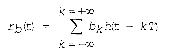
- the received signal may be defined as a temporary function r(t) obtained as a summation of a sequence of symbols to be transmitted a k : where T is the duration of a given symbol and h(t) is the impulsive response of the transmission system.
- transmission system is understood the set of filters in transmission, of the transmission channel (supposed to be linear and stationary) and of filters in reception.
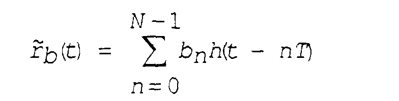
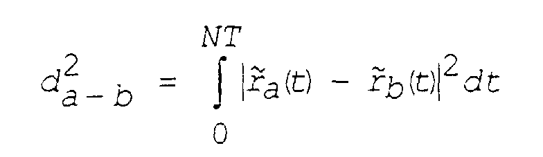
- the optimum demodulator In case of white Gaussian noise the optimum demodulator must be able to calculate for all possible transmitted sequences b k the distance between the signal really received r(t) and the signal r b (t) that would have been received in case of transmission of sequence b k : and to choose the sequence b k to which corresponds the minimum value of this distance.
- the decoding error probability of the received signals is very sensible to the minimum value of this distance, we define d min and which turns out, for what said, a function of the impulsive response h(t).
- a n and b n are supposed to be two possible sequences of transmitted symbols, (t) and (t) the complex envelopes of the corresponding received signals, and d a-b the distance between these signals. All these elements are defined in the following way: where h(t) is the complex envelopes of the impulsive response of the transmission system and N is the number of transmitted symbols.
- a multibeam array 10 allowing to receive with n different radiation diagrams makes n different channels available with the same number of impulsive responses h l (t)...h n (t). Therefore the selection of the best beam may be made (if all impulsive responses h(t) are known) choosing the one representing the maximum value of the parameter d min .
- the GSM transmission standard foresees the transmission, at the centre of every burst, of a training sequence enabling the receiver to estimate precisely the impulsive response h(t).
- the method foresees to carry out this estimation upstream the receiver and to use it both for the selection of the beam and inside of the receiver to implement the matched filter.
- a training sequence c n is introduced, known at the receiver.
- this training sequence c n is inserted at the centre of the burst.
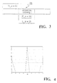
- the training sequence has a duration L tr equal to 26 bits and is periodical with a period P tr equal to sixteen bits, as illustrated in figure 3.
- the impulsive response may be estimated correlating the received signal samples with the symbols c k
- the required computational load for the estimation is absolutely not heavy for the receiver set. As an example it is possible to consider that for each sample of the response fifteen sums are necessary, and in the example taken into consideration four samples for each symbol have been estimated, for a total of six symbols.
- the here described method may anyhow be extended to other radiomobile standards using at the receiver an estimate of the transmission system impulsive response h(t).
Abstract
Description
- figure 1 shows a schematic view of a GSM signal transceiver provided with an "intelligent" antenna;
- figure 2 shows a flow scheme of operating phases of the receiver of fig. 1 according to the method according to the present invention;
- figure 3 shows a schematic representation of position, length and period of a training sequence of a normal burst received by the receiver of figure 1;
- figure 4 shows an autocorrelation diagram related to the signal of figure 3.

an and bn are supposed to be two possible sequences of transmitted symbols,


Claims (3)
- Method for the selection of a beam among those formed by a multibeam antenna, in particular radiomobile systems comprising a receiver set of radio frequency signals provided with an array (10) of radiant and/or receiving elements, a beam former (5) connected downstream of the array and a best beam selection device (9) connected to the beam former (5), characterised in that in said selection device (9) of the best beam that beam will be chosen which presents the minimum value of an estimation of the decoding error probability of the received signals.
- Method according to claim 2, characterised in that this minimum estimation value of the decoding error probability of the received signals is proportional to a maximum value of a parameter (dmin) defined as the minimum distance between the received signals related to all combinations of two different sequences (an, bn) of transmitted symbols.
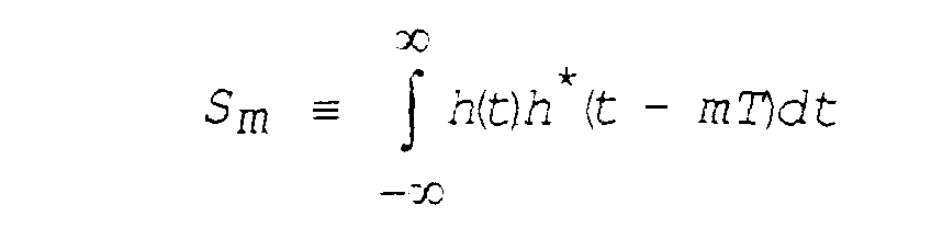
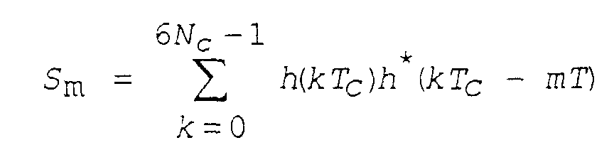
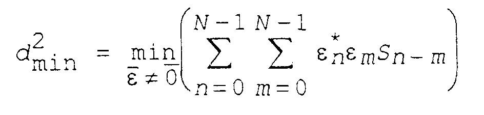
- Method according to claim 2, characterised in that operations carried out by the selection device (9) for each beam are:.. an an estimation of the impulsive response h(t) of transmission system;.. a calculation of the autocorrelation of said impulsive response according to the following formula:
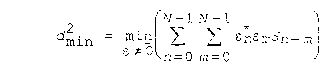
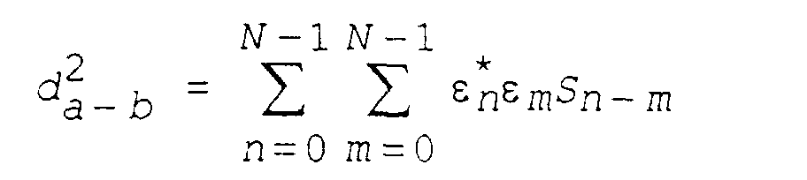
 a calculation of said minimum distance to the square according to the following equation:where εn is the difference sequence defined as ε n ≡ an - bn and N is the number of transmitted symbols.
Applications Claiming Priority (2)
| Application Number | Priority Date | Filing Date | Title |
|---|---|---|---|
| IT96MI001369A IT1285217B1 (en) | 1996-07-04 | 1996-07-04 | METHOD FOR THE AUTOMATIC SELECTION OF A BEAM AMONG THOSE FORMED BY A MULTI BEAM ANTENNA, PARTICULARLY FOR MOBILE RADIO SYSTEMS |
| ITMI961369 | 1996-07-04 |
Publications (3)
| Publication Number | Publication Date |
|---|---|
| EP0817308A2 true EP0817308A2 (en) | 1998-01-07 |
| EP0817308A3 EP0817308A3 (en) | 1998-04-08 |
| EP0817308B1 EP0817308B1 (en) | 2002-11-27 |
Family
ID=11374530
Family Applications (1)
| Application Number | Title | Priority Date | Filing Date |
|---|---|---|---|
| EP97111319A Expired - Lifetime EP0817308B1 (en) | 1996-07-04 | 1997-07-04 | Method for the automatic selection of one beam among those formed by a multibeam antenna, in particular for radiomobile systems |
Country Status (3)
| Country | Link |
|---|---|
| EP (1) | EP0817308B1 (en) |
| DE (1) | DE69717354T2 (en) |
| IT (1) | IT1285217B1 (en) |
Cited By (3)
| Publication number | Priority date | Publication date | Assignee | Title |
|---|---|---|---|---|
| WO2001013463A1 (en) * | 1999-08-16 | 2001-02-22 | Telefonaktiebolaget Lm Ericsson (Publ) | Method of and apparatus for beam reduction and combining in a radio communications system |
| WO2001091325A1 (en) * | 2000-05-25 | 2001-11-29 | Siemens Aktiengesellschaft | Method for controlling the formation of a downlink beam |
| WO2009080101A1 (en) * | 2007-12-20 | 2009-07-02 | Telefonaktiebolaget Lm Ericsson (Publ) | An improved antenna arrangement in an electronic device |
Citations (4)
| Publication number | Priority date | Publication date | Assignee | Title |
|---|---|---|---|---|
| US5303240A (en) * | 1991-07-08 | 1994-04-12 | Motorola, Inc. | Telecommunications system using directional antennas |
| WO1996023329A1 (en) * | 1995-01-27 | 1996-08-01 | Hazeltine Corporation | High gain antenna systems for cellular use |
| US5590399A (en) * | 1995-02-23 | 1996-12-31 | Nextel Communications | Up-link channel assignment scheme for cellular mobile communications systems employing multi-beam antennas with beam selection |
| WO1997044978A1 (en) * | 1996-05-22 | 1997-11-27 | Nokia Telecommunications Oy | Method and system for selecting an antenna beam of a base station of a radio system |
-
1996
- 1996-07-04 IT IT96MI001369A patent/IT1285217B1/en active IP Right Grant
-
1997
- 1997-07-04 DE DE69717354T patent/DE69717354T2/en not_active Expired - Fee Related
- 1997-07-04 EP EP97111319A patent/EP0817308B1/en not_active Expired - Lifetime
Patent Citations (4)
| Publication number | Priority date | Publication date | Assignee | Title |
|---|---|---|---|---|
| US5303240A (en) * | 1991-07-08 | 1994-04-12 | Motorola, Inc. | Telecommunications system using directional antennas |
| WO1996023329A1 (en) * | 1995-01-27 | 1996-08-01 | Hazeltine Corporation | High gain antenna systems for cellular use |
| US5590399A (en) * | 1995-02-23 | 1996-12-31 | Nextel Communications | Up-link channel assignment scheme for cellular mobile communications systems employing multi-beam antennas with beam selection |
| WO1997044978A1 (en) * | 1996-05-22 | 1997-11-27 | Nokia Telecommunications Oy | Method and system for selecting an antenna beam of a base station of a radio system |
Cited By (6)
| Publication number | Priority date | Publication date | Assignee | Title |
|---|---|---|---|---|
| WO2001013463A1 (en) * | 1999-08-16 | 2001-02-22 | Telefonaktiebolaget Lm Ericsson (Publ) | Method of and apparatus for beam reduction and combining in a radio communications system |
| US6470192B1 (en) | 1999-08-16 | 2002-10-22 | Telefonaktiebolaget Lm Ericcson (Publ) | Method of an apparatus for beam reduction and combining in a radio communications system |
| WO2001091325A1 (en) * | 2000-05-25 | 2001-11-29 | Siemens Aktiengesellschaft | Method for controlling the formation of a downlink beam |
| US7039368B2 (en) | 2000-05-25 | 2006-05-02 | Siemens Aktiengesellschaft | Method for controlling the formation of a downlink beam |
| KR100767129B1 (en) * | 2000-05-25 | 2007-10-15 | 지멘스 악티엔게젤샤프트 | Method for controlling the formation of a downlink beam |
| WO2009080101A1 (en) * | 2007-12-20 | 2009-07-02 | Telefonaktiebolaget Lm Ericsson (Publ) | An improved antenna arrangement in an electronic device |
Also Published As
| Publication number | Publication date |
|---|---|
| IT1285217B1 (en) | 1998-06-03 |
| EP0817308B1 (en) | 2002-11-27 |
| DE69717354D1 (en) | 2003-01-09 |
| DE69717354T2 (en) | 2003-09-18 |
| ITMI961369A0 (en) | 1996-07-04 |
| ITMI961369A1 (en) | 1998-01-04 |
| EP0817308A3 (en) | 1998-04-08 |
Similar Documents
| Publication | Publication Date | Title |
|---|---|---|
| US10686513B2 (en) | Method and apparatus for smart adaptive dynamic range multiuser detection radio receiver | |
| Russer | Signal processing for wideband smart antenna array applications | |
| EP0818059B1 (en) | Wide antenna lobe | |
| US6173014B1 (en) | Method of and apparatus for interference rejection combining and downlink beamforming in a cellular radio communications system | |
| US7929922B2 (en) | Radio communication system, a transmitter and a receiver | |
| KR100426110B1 (en) | Radio communication apparatus and radio communication method | |
| Miura et al. | Beamforming experiment with a DBF multibeam antenna in a mobile satellite environment | |
| EP1071159A2 (en) | A two-way paging system and apparatus | |
| EP1344276B1 (en) | Base station, base station module and method for direction of arrival estimation | |
| AU695327B2 (en) | Diversity combining for antennas | |
| US7894857B2 (en) | Method including a radio transmitter for improving radio link operation | |
| WO1998049786A3 (en) | Adaptive communication system and method using unequal weighting of interference and noise | |
| US6321066B1 (en) | Method and apparatus for directional radio communication | |
| US20120086602A1 (en) | Hybrid beam forming apparatus in wideband wireless communication system | |
| CN100428651C (en) | Down wave beam shaping method and device of radio channel | |
| AU2003200262B2 (en) | Improved radio signal repeater | |
| CA2300043C (en) | Array antenna transmitter with a high transmission gain proportional to the number of antenna elements | |
| US5889825A (en) | Method of parameterizing a receiving device, and also a corresponding receiving device and radio station | |
| EP0817308A2 (en) | Method for the automatic selection of one beam among those formed by a multibeam antenna, in particular for radiomobile systems | |
| US20070249308A1 (en) | Method and apparatus for uplink coverage improvement | |
| EP0921646A3 (en) | Digital radio communication system with diversity reception | |
| WO2000035116A3 (en) | Method and system for generating defined directional characteristics | |
| Kim et al. | Performance analysis of fading reduction using the diversity antenna and 2× 2 smart antenna for 802.11 p WAVE V2V communication | |
| Sibille | Compared performance of UWB antennas for time and frequency domain modulation | |
| Miura et al. | A land‐mobile satellite tracking experiment with a DBF self‐beam steering array antenna |
Legal Events
| Date | Code | Title | Description |
|---|---|---|---|
| PUAI | Public reference made under article 153(3) epc to a published international application that has entered the european phase |
Free format text: ORIGINAL CODE: 0009012 |
|
| AK | Designated contracting states |
Kind code of ref document: A2 Designated state(s): DE FI FR GB SE |
|
| PUAL | Search report despatched |
Free format text: ORIGINAL CODE: 0009013 |
|
| AK | Designated contracting states |
Kind code of ref document: A3 Designated state(s): AT BE CH DE DK ES FI FR GB GR IE IT LI LU MC NL PT SE |
|
| AKX | Designation fees paid |
Free format text: DE FI FR GB SE |
|
| RBV | Designated contracting states (corrected) |
Designated state(s): DE FI FR GB SE |
|
| RAP3 | Party data changed (applicant data changed or rights of an application transferred) |
Owner name: ITALTEL S.P.A. |
|
| 17P | Request for examination filed |
Effective date: 19981012 |
|
| 17Q | First examination report despatched |
Effective date: 20011214 |
|
| GRAG | Despatch of communication of intention to grant |
Free format text: ORIGINAL CODE: EPIDOS AGRA |
|
| GRAG | Despatch of communication of intention to grant |
Free format text: ORIGINAL CODE: EPIDOS AGRA |
|
| GRAH | Despatch of communication of intention to grant a patent |
Free format text: ORIGINAL CODE: EPIDOS IGRA |
|
| GRAH | Despatch of communication of intention to grant a patent |
Free format text: ORIGINAL CODE: EPIDOS IGRA |
|
| RAP1 | Party data changed (applicant data changed or rights of an application transferred) |
Owner name: SIEMENS MOBILE COMMUNICATIONS S.P.A. |
|
| GRAA | (expected) grant |
Free format text: ORIGINAL CODE: 0009210 |
|
| AK | Designated contracting states |
Kind code of ref document: B1 Designated state(s): DE FI FR GB SE |
|
| REG | Reference to a national code |
Ref country code: GB Ref legal event code: FG4D |
|
| REF | Corresponds to: |
Ref document number: 69717354 Country of ref document: DE Date of ref document: 20030109 |
|
| ET | Fr: translation filed | ||
| PLBE | No opposition filed within time limit |
Free format text: ORIGINAL CODE: 0009261 |
|
| STAA | Information on the status of an ep patent application or granted ep patent |
Free format text: STATUS: NO OPPOSITION FILED WITHIN TIME LIMIT |
|
| 26N | No opposition filed |
Effective date: 20030828 |
|
| PGFP | Annual fee paid to national office [announced via postgrant information from national office to epo] |
Ref country code: DE Payment date: 20070731 Year of fee payment: 11 |
|
| PGFP | Annual fee paid to national office [announced via postgrant information from national office to epo] |
Ref country code: FI Payment date: 20070713 Year of fee payment: 11 |
|
| PGFP | Annual fee paid to national office [announced via postgrant information from national office to epo] |
Ref country code: GB Payment date: 20070720 Year of fee payment: 11 |
|
| PGFP | Annual fee paid to national office [announced via postgrant information from national office to epo] |
Ref country code: SE Payment date: 20070712 Year of fee payment: 11 |
|
| PGFP | Annual fee paid to national office [announced via postgrant information from national office to epo] |
Ref country code: FR Payment date: 20070710 Year of fee payment: 11 |
|
| EUG | Se: european patent has lapsed | ||
| GBPC | Gb: european patent ceased through non-payment of renewal fee |
Effective date: 20080704 |
|
| PG25 | Lapsed in a contracting state [announced via postgrant information from national office to epo] |
Ref country code: DE Free format text: LAPSE BECAUSE OF NON-PAYMENT OF DUE FEES Effective date: 20090203 |
|
| REG | Reference to a national code |
Ref country code: FR Ref legal event code: ST Effective date: 20090331 |
|
| PG25 | Lapsed in a contracting state [announced via postgrant information from national office to epo] |
Ref country code: FI Free format text: LAPSE BECAUSE OF NON-PAYMENT OF DUE FEES Effective date: 20080704 |
|
| PG25 | Lapsed in a contracting state [announced via postgrant information from national office to epo] |
Ref country code: GB Free format text: LAPSE BECAUSE OF NON-PAYMENT OF DUE FEES Effective date: 20080704 |
|
| PG25 | Lapsed in a contracting state [announced via postgrant information from national office to epo] |
Ref country code: FR Free format text: LAPSE BECAUSE OF NON-PAYMENT OF DUE FEES Effective date: 20080731 |
|
| PG25 | Lapsed in a contracting state [announced via postgrant information from national office to epo] |
Ref country code: SE Free format text: LAPSE BECAUSE OF NON-PAYMENT OF DUE FEES Effective date: 20080705 |