Field of the Invention
This invention relates to multimedia communications, and more
particularly, to multimedia messaging systems.
Background of the Invention
Multimedia conferencing allows parties to meet face-to-face without
traveling. Presently available multimedia conferencing workstations are suitable
for desk top use and support simultaneous video, audio, and data. Multimedia
calls can be placed using Integrated Services Digital Network (ISDN) lines in the
public switched telephone network by calling a party's multimedia number. If the
called party answers, the call can be completed immediately. If the called party's
line is busy or if the called party is absent or unable to answer the call, a
multimedia messaging system is needed to answer the call.
To ensure that multimedia calls are answered even when the called party's
multimedia workstation is off or otherwise not available to receive messages,
multimedia messaging functions can be provided by a network-based service
provider, rather than by the called party's own workstation. A network-based
multimedia messaging system is described in commonly-assigned copending U.S.
patent application Serial No. 08/792,339, filed January 31, 1997 ("the '339
application"), which is hereby incorporated by reference herein. As described in
the '339 application, if the public switched telephone network is provided with the
appropriate switching capabilities, the network can redirect unanswered
multimedia calls to a user's multimedia mailbox on a special messaging server.
The call answering functions of the '339 application are based on the
capabilities of a class of network switch known as the 5ESSTM (electronic
switching system) switch implemented at the generic 6 level or above. When a
calling party attempts to reach a called party who is unavailable, the 5ESSTM
switch at the called party's local exchange carrier (LEC) network redirects the call
to the special messaging server. In order for the messaging server to play the
greeting for the correct called party and to record and store the calling party's
message in the appropriate mailbox location, the 5ESSTM switch provides called
party identification (ID) information (sometimes called automatic number
identification or ANI) to the messaging server. However, if the messaging server
is located in a different local or interexchange carrier network, a portion of the
called party ID information supplied by the 5ESSTM switch might be omitted or
might not be provided in the appropriate data field. As a result, the messaging
server would not be able to identify the intended recipient of the message.
Although the messaging system of the '339 application is satisfactory, it would be
desirable to be able to provide a messaging system that is less dependent on the
extent to which 5ESSTM switches are deployed in the network.
It is therefore an object of the present invention to provide a
communications system with improved multimedia messaging service
capabilities.
Summary of the Invention
This and other objects of the invention are accomplished in accordance
with the principles of the present invention by providing a communications
system in which a World Wide Web (Web) server is used to perform multimedia
messaging functions. The Web server provides a user interface by supplying Web
pages to multimedia workstations over the Internet. The Web pages include a
variety of multimedia calling and messaging options. For example, a party at a
workstation can select a party to be called from directory information displayed
on the workstation.
Multimedia workstations are interconnected by a multimedia bridge
system and the public switched telephone network (PSTN). Parties are provided
with multimedia mailboxes on message servers that are connected to the PSTN
and the Internet. In order to identify the message server on which the called
party's mailbox is located when a call is unanswered, the Web server provides the
multimedia number of the called party's message server to the multimedia bridge
system when a call is made. In addition, the Web server provides the multimedia
number of the called party. The called party multimedia number from the Web
server is used to identify the proper mailbox in which to store a message for the
called party. To record a message, the multimedia bridge system establishes a
multimedia connection between the calling party and the called party's mailbox on
the appropriate message server. Because the call is rerouted by the multimedia
bridge system rather than by specialized switches within the PSTN, the system
allows multimedia calls to be answered even if the message server of the called
party is located across a local or interexchange network.
Additional multimedia message feature, such as message or greeting
playback, greeting recording, and various mailbox management functions are also
provided by the system. These features are invoked through the user interface
provided by the Web pages displayed at the user's workstation. Parties are given
access to multimedia mailboxes without being required to know on which
message server a particular mailbox is located.
Further features of the invention, its nature and various advantages will be
more apparent from the accompanying drawings and the following detailed
description of the preferred embodiments.
Brief Description of the Drawings
FIG. 1 is a diagram of a communications system that supports multimedia
messaging in accordance with the principles of the present invention.
FIG. 2 is a flow chart showing steps involved in call answering using the
communications system of FIG. 1.
FIG. 3 is a flow chart showing steps involved in multimedia message
playback using the communications system of FIG. 1.
FIG. 4 is a flow chart showing steps involved in sending a multimedia
message using the communications system of FIG. 1.
FIG. 5 is a flow chart showing steps involved in recording a greeting using
the communications system of FIG. 1.
Detailed Description of the Preferred Embodiments
As shown in FIG. 1, in communications system 10, transport network 12
interconnects multimedia workstations 14. Parties at workstations 14 can
originate or receive multimedia calls having video, audio, and data components.
Transport network 12 is preferably the public switched telephone network
(PSTN). Workstations 14 are connected to transport network 12 via lines 16,
which may be any suitable communication paths for supporting realtime
multimedia communications. Preferably, lines 16 and the associated paths within
transport network 12 are Integrated Services Digital Network (ISDN) lines.
A party at one of workstations 14 (e.g., workstation 14a) can place a
multimedia call to a party at another of workstations 14 (e.g., workstation 14d)
directly though transport network 12 using the multimedia number (a 10 digit
number analogous to a standard telephone number) of the party to be called.
Alternatively, multimedia bridge system 18 can be used with transport network 12
to interconnect workstations 14. Using multimedia bridge system 18 allows
conference calls to be established between multiple parties.
Workstations 14a and 14d are connected to data network 20, which is
preferably the Internet, via lines 22 and 24, respectively. Lines 22 and 24 are
typically plain old telephone service (POTS) lines or the lines of a private data
network. If desired, lines 22 and 24 may be ISDN lines. Workstation 14b is
connected to data network 20 via line 16b, transport network 12, and gateway
server 26, which avoids the need for workstation 14b to have a second
communication line, such as line 22 or 24. The use of a gateway server to provide
a connection to a data network is described in commonly-assigned copending U.S.
patent application Serial No. 08/547,216, filed October 24, 1995, which is hereby
incorporated by reference herein. Standard multimedia workstation 14c is
connected to transport network 12, but not data network 20 to illustrate that
parties at workstations 14a, 14b, and 14d can communicate with a standard
multimedia workstation, if desired.
Workstations 14a, 14b and 14d are connected to World Wide Web (Web)
server 28 via data network 20. Preferably, data network 20 is the Internet.
Directory information, such as the multimedia numbers of various parties can be
provided to workstations 14a, 14b, and 14d in the form of Web pages, as
described in commonly-assigned copending U.S. patent application Serial No.
08/671,223, filed June 27, 1996, which is hereby incorporated by reference herein.
In addition, Web server 28 provides a user interface that allows the parties to
record multimedia greetings, record and send messages, and perform other
multimedia mailbox functions.
A party at workstation 14a, 14b, or 14d can select a party to be called from
directory information displayed at that workstation as Web pages from Web
server 28. When a party is selected, directory information including information
identifying the called party's message server and multimedia mailbox is provided
to multimedia bridge system 18, which establishes a multimedia connection
between the workstation 14 of the calling party and the workstation 14 of the
called party via transport network 12. The directory information is provided to
multimedia bridge system 18 by Web server 28 directly via line 30 or via data
network 20 using lines 32 and 34. The directory information may be stored on
directory server 36, which is accessed by Web server 28 directly via line 38 or via
data network 20 using lines 32 and 40. If desired, directory server 36 may be colocated
with Web server 28.
Message servers 42 and 44 are used to play multimedia greetings and to
record multimedia messages when the multimedia number of the called party is
not answered. Message servers can be connected directly to Web server 28 or can
be connected to Web server 28 via data network 20. For example, message server
44 is directly connected to Web server 28 via line 45 and message server 42 is
connected to Web server 28 via data network 20. An advantage of the
arrangement of communications system 10 is that if the storage capacity of one
message server is reached, additional greetings and messages may be stored at
another message server. Parties interact with message servers 42 and 44 via the
user interface provided by Web server 28, so parties are not required to know
which particular message server is being used.
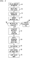
FIG. 2 shows steps involved in recording an unanswered multimedia call.
At step 46, the calling party retrieves Web pages containing multimedia directory
information from Web server 28. The directory information preferably contains
the names of various parties with multimedia workstations and their
corresponding multimedia numbers. In order to provide multimedia message
answering, the directory information includes the multimedia number of the
message server on which the called party's multimedia messages are to be stored.
For example, if the called party has a multimedia mailbox on message server 42
(FIG. 1), then the multimedia number by which an ISDN link can be established
to message server 42 (FIG. 1) via transport network 12 (FIG. 1) is included with
the other directory information for the called party. If desired, the directory
information may contain home and business addresses, fax, e-mail, and telephone
numbers, and images of the parties.
At step 48, the calling party selects the party to be called from the
displayed directory information. A request to initiate the multimedia call based
on the directory information for the selected party is provided to multimedia
bridge 18 by the calling party's workstation at step 50. The request preferably
contains the calling party's multimedia number, the called party's multimedia
number, and the multimedia number of the message server on which the called
party's mailbox is located. At step 52, multimedia bridge system 18 initiates a
multimedia call between the calling party (at, e.g., workstation 14a) and the called
party (at, e.g., workstation 14d) by establishing a communication path to
workstation 14a using ISDN line 54 (FIG. 1) and by establishing a
communication path to workstation 14d via ISDN line 56 (FIG. 1).
If a multimedia call is established at step 58, the call is completed at step
60. If, however, multimedia bridge system 18 determines that a multimedia call
connection has not been established at step 58, because the line is busy or the
called party has not answered within a predetermined time period, a multimedia
message connection with the called party's message server is established at step
62. The multimedia bridge 18 establishes the multimedia message connection at
step 62 using the multimedia number for the called party's message server (e.g.,
message server 42) that was provided when setting up the multimedia call at steps
46, 48, 50, and 52.
In order for message server 42 to play the appropriate greeting and to store
the incoming multimedia call in the correct multimedia mailbox, mailbox
functions in message server 42 are preferably organized by the multimedia
numbers of the parties. After a multimedia connection is established between, for
example, workstation 14a and message server 42, multimedia bridge system 18
provides message server 42 with the multimedia number or other suitable
addressing information for the called party at step 64. At step 66, message server
42 plays the prerecorded multimedia greeting associated with the called party's
multimedia number. The calling party leaves a multimedia message for the called
party on message server 42 at step 68. The message is stored in the mailbox
associated with the called party's multimedia number.
The called party is preferably alerted that a multimedia message has been
received at step 70. Any suitable technique for alerting the called party may be
used. For example, message server 42 can call the called party's telephone voice
mail system and leave a voice mail message. Message server 42 could also
activate an alerting signal indicator on workstation 14d. If desired, an e-mail or
fax message could be sent. An alerting message can also be sent to the called
party via Web server 28.
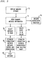
Whenever a party wishes to accesses his mailbox, such as after being
alerted that his mailbox contains a multimedia message, the user retrieves Web
pages from Web server 28 that provide a list of mailbox options, such as "send a
message" or "record a greeting." As shown in FIG. 3, after displaying the
mailbox options at step 72, the party can view summary information for the
messages stored in the mailbox at step 74. The summary message information
preferably includes the length of the message, the time that the message was
received, and the name and multimedia number of the calling party. Other
directory information associated with the calling party can be provided, if desired.
Certain mailbox management functions are preferably available while the
summary message information is being displayed at step 74. For example, at step
76, message mailbox management functions such as deleting, archiving,
annotating, or forwarding multimedia messages can be performed.
If the party desires to view one of the messages listed in the message
summary, the message to be viewed is selected at step 78. The party's
workstation (e.g., workstation 14d) generates a message playback request. The
message may be played back using two approaches.
The first approach involves using Web server 28 to provide the playback
request to multimedia bridge system 18 and message server 42. At step 80,
multimedia bridge system 18 establishes a multimedia connection between the
message server containing the user's mailbox (message server 42) and the user's
workstation 14d. The message can then be played back by message server 42
over this connection at step 82.
The second approach involves establishing a direct communication link
between message server 42 and workstation 14d. The playback request from
workstation 14d can contain service request commands that direct message server
42 to establish a direct communication link with workstation 14d via transport
network 12 at step 80. The service commands are supplied over data network 20.
The message is played back over a direct ISDN connection through transport
network 12 at step 82. Commonly-assigned copending U.S. patent application
Serial No. 08/747,576, filed January 1, 1997, which is hereby incorporated by
reference herein, describes how a first server (like workstation 14d) can use
service requests transmitted over the Internet to establish a communication link
with a second server (like message server 42) over the PSTN.
If desired, after a party views the summary message information at step
74, the party can return a call at step 84 by selecting a party to be called directly
from the listed summary information. Workstation 14d generates a request to
initiate a multimedia call, which is preferably provided to multimedia bridge
system 18 via Web server 28. At step 86, multimedia bridge system 18
establishes a multimedia call between the party at workstation 14d and the party
that was selected from the summary information at step 84.
A party may sometimes wish to leave a multimedia message for a given
recipient without first attempting to place a multimedia call. Steps involved in
recording and sending a multimedia message are shown in FIG. 4. At step 88, the
party sending the message selects a party to receive the multimedia message.
Preferably, the sender selects the intended recipient from a list of directory
information supplied by Web server 28 to the sender's workstation 14 (e.g.,
workstation 14a) in the form of Web pages. Two approaches may be used to
record the message for the recipient. The first approach involves using Web
server 28 to provide a request to multimedia bridge system 18 to establish a
multimedia connection between workstation 14a and message server 42. At step
80, multimedia bridge system 18 establishes a multimedia connection between
message server 42 and workstation 14a. Message server 42 is provided with the
multimedia number of the intended recipient, so that message server 42 can store
the message in the proper mailbox. At step 92, the sender leaves the message for
the recipient over the connection that was established at step 90. The second
approach involves establishing a direct communication link between message
server 42 and workstation 14a at step 90 using service requests from workstation
14a supplied over data network 20, as described in above-mentioned U.S. patent
application Serial No. 08/747,576. Message server 42 is provided with the
multimedia number of the intended recipient at step 90, so that the message can be
stored in the proper mailbox on message server 42 when the message is left by the
sender at step 92.
Steps involved in recording a greeting are shown in FIG. 5. At step 94, a
party desiring to record a greeting directs his workstation 14 (e.g., workstation
14a) to display his mailbox options in the form of Web pages from Web server
28. When the party selects the option of "record a greeting," a multimedia
connection is established between workstation 14a and the message server
containing his mailbox (e.g., message server 42). When initiating the connection,
workstation 14a supplies the multimedia number of the party or other suitable
identification information, so that message server 42 can associate the recorded
greeting with the appropriate mailbox. Two approaches may be used to establish
the multimedia connection between message server 42 and workstation 14a. The
first approach involves using Web server 28 to provide a request to multimedia
bridge system 18 to establish a multimedia connection between workstation 14a
and message server 42. At step 96, multimedia bridge system 18 establishes a
multimedia connection between message server 42 and workstation 14a. Because
message server 42 is provided with the multimedia number of the party, message
server 42 records the new greeting in the proper mailbox at step 98 over the
connection that was established at step 96. The second approach involves
establishing a direct communication link between message server 42 and
workstation 14a at step 96 using service requests from workstation 14a supplied
over data network 20, as described in the above-mentioned U.S. patent application
Serial No. 08/747,576. Because message server 42 has the multimedia number of
the party, the greeting can be recorded in the proper mailbox on message server 42
at step 98.