EP0820905A1 - Knee-bolster device - Google Patents
Knee-bolster device Download PDFInfo
- Publication number
- EP0820905A1 EP0820905A1 EP97111296A EP97111296A EP0820905A1 EP 0820905 A1 EP0820905 A1 EP 0820905A1 EP 97111296 A EP97111296 A EP 97111296A EP 97111296 A EP97111296 A EP 97111296A EP 0820905 A1 EP0820905 A1 EP 0820905A1
- Authority
- EP
- European Patent Office
- Prior art keywords
- protection device
- gas bag
- knee protection
- knee
- gas
- Prior art date
- Legal status (The legal status is an assumption and is not a legal conclusion. Google has not performed a legal analysis and makes no representation as to the accuracy of the status listed.)
- Granted
Links
Images


Classifications
-
- B—PERFORMING OPERATIONS; TRANSPORTING
- B60—VEHICLES IN GENERAL
- B60R—VEHICLES, VEHICLE FITTINGS, OR VEHICLE PARTS, NOT OTHERWISE PROVIDED FOR
- B60R21/00—Arrangements or fittings on vehicles for protecting or preventing injuries to occupants or pedestrians in case of accidents or other traffic risks
- B60R21/02—Occupant safety arrangements or fittings, e.g. crash pads
- B60R21/16—Inflatable occupant restraints or confinements designed to inflate upon impact or impending impact, e.g. air bags
- B60R21/20—Arrangements for storing inflatable members in their non-use or deflated condition; Arrangement or mounting of air bag modules or components
- B60R21/205—Arrangements for storing inflatable members in their non-use or deflated condition; Arrangement or mounting of air bag modules or components in dashboards
- B60R21/206—Arrangements for storing inflatable members in their non-use or deflated condition; Arrangement or mounting of air bag modules or components in dashboards in the lower part of dashboards, e.g. for protecting the knees
-
- B—PERFORMING OPERATIONS; TRANSPORTING
- B60—VEHICLES IN GENERAL
- B60R—VEHICLES, VEHICLE FITTINGS, OR VEHICLE PARTS, NOT OTHERWISE PROVIDED FOR
- B60R21/00—Arrangements or fittings on vehicles for protecting or preventing injuries to occupants or pedestrians in case of accidents or other traffic risks
- B60R21/02—Occupant safety arrangements or fittings, e.g. crash pads
- B60R21/16—Inflatable occupant restraints or confinements designed to inflate upon impact or impending impact, e.g. air bags
- B60R21/20—Arrangements for storing inflatable members in their non-use or deflated condition; Arrangement or mounting of air bag modules or components
- B60R21/215—Arrangements for storing inflatable members in their non-use or deflated condition; Arrangement or mounting of air bag modules or components characterised by the covers for the inflatable member
- B60R2021/21531—Arrangements for storing inflatable members in their non-use or deflated condition; Arrangement or mounting of air bag modules or components characterised by the covers for the inflatable member using a strechable wall liner
-
- B—PERFORMING OPERATIONS; TRANSPORTING
- B60—VEHICLES IN GENERAL
- B60R—VEHICLES, VEHICLE FITTINGS, OR VEHICLE PARTS, NOT OTHERWISE PROVIDED FOR
- B60R21/00—Arrangements or fittings on vehicles for protecting or preventing injuries to occupants or pedestrians in case of accidents or other traffic risks
- B60R21/02—Occupant safety arrangements or fittings, e.g. crash pads
- B60R21/16—Inflatable occupant restraints or confinements designed to inflate upon impact or impending impact, e.g. air bags
- B60R21/23—Inflatable members
- B60R21/231—Inflatable members characterised by their shape, construction or spatial configuration
- B60R2021/23169—Inflatable members characterised by their shape, construction or spatial configuration specially adapted for knee protection
Definitions
- the invention relates to a knee protection device for vehicle occupants, with an airbag in the footwell of a vehicle, a Gas generator and a gas bag cover made of energy absorbing Material.
- a generic knee protection device is known from US Pat. No. 3,784,223 known.
- a knee protection device prevents a unintended vehicle occupant in the event of a collision Descend towards the knee room.
- the airbag below the steering column behind an airbag cover arranged, which has a tear line.
- the unfolding gas bag breaks through the cover and unfolds towards the knees of the vehicle's occupants for their movement intercept.
- Regarding the location of the destroyed gas bag cover must always ensure that an occupant does not collide bumps into them and injures them.
- the gas bag cover is designed as a pivotable flap is, whereby it must also be excluded here that the vehicle occupant can injure the flap in the event of a collision.
- the invention provides a knee protection device for vehicle occupants, which is characterized by a small space requirement and a good protection. It also offers vehicle occupants adequate protection that is outside the middle Seated position.
- a knee protection device at the beginning mentioned type this is achieved according to the invention in that the In the event of a collision, the gas bag is covered by the inflated gas bag outwards, is deformed towards the footwell of the vehicle and forms a knee pad together with the gas bag.
- the gas bag does not penetrate or unfold the cover when unfolded, as is the case with the knee protection devices known to date but only deforms it towards the knees of the occupant, so that they hit a soft knee pad in the event of a collision.
- the knee protection device according to the invention is light, requires little Space and few components.
- the hardness of the gas bag and thus the entire knee pad can be set by various measures, for example by Providing outflow openings on the gas bag or using a multi-stage gas generator.
- the gas bag cover is preferably covered by the gas bag on the Outside of the cover only about 10 to 100 mm in the direction Footwell deformed from its initial state. This will a sliding of the knees away from the middle sitting position existing occupants prevented.
- Fig. 1 is a knee protection device arranged in the footwell of the vehicle 1 for the driver's side and a knee protection device 3 shown for the passenger side.
- Each individual knee protection device 1, 3 has one Airbag 5, 7, the airbags 5, 7 in FIG. 1 being inflated Condition and are shown by broken lines. Every gas bag 5, 7 is hidden in the upper area of the dashboard arranged gas generator 9, 11 assigned.
- the knee guards 1, 3 each further comprise an airbag cover 13, 15, which the Cover gas bags 5, 7 when inflated and not inflated.
- the gas bag covers 13, 15 are made of a soft, energy absorbent material deformable by the gas bag 5, 7.
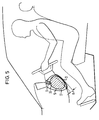
- the Thickness of the gas bag covers 13, 15 and their material are so on Volume of the assigned gas bags 5, 7 and their hardness in inflated state matched that they during the inflation of the Gas bags 5, 7 deformed towards the knees of the vehicle occupants will. This is the fig. 4 and 5 can be seen more clearly. 4 the gas bag 5 is shown in the not yet deployed state.
- a Cavity 17 provided in the dashboard behind the cover 13 is not completely filled by the gas bag 5.
- the cavity 17th is shown oversized in Fig. 4.
- pyrotechnic contained in the gas generator 9 Material ignites or a stored gas volume released and flows through a plurality of outflow openings 19 in his Housing in the interior of the gas bag 5 and inflates it.
- the gas bag 5 hits the inside of the Airbag cover 13 and, as can be seen in FIG. 5, deformed this towards the knees of the occupant.
- the gas bag cover 13 It does not tear open or fold away and forms with it her gas bag 5 a knee pad against which the knees of the Beat vehicle occupants, preventing the Vehicle occupants can dive down into the knee area.
- the knee protection devices 1, 3 effectively stabilize the situation of the vehicle occupant.
- the knee protection devices 1.3 formed knee pads take the kinetic energy of against them bouncing knees and cushioning the impact. Yourself outside the occupants in the middle of the seating position cannot access the Knee protectors 1, 3 slide past, as these are not the usual, large-volume gas bags emerging from a cover, the shape of which is tailored to a medium seating position, but rather extend across the entire footwell.
- the knees hitting the gas bag covers 13, 15 are not fixed in all directions as they hit knee pads and do not immerse in and in large-volume gas bags, as with one Ball joint, which leads to a higher load on the Femur in the axial direction. At the knee pad still have their knees in the vertical and horizontal directions Freedom of movement.
- each knee pad is determined by the hardness of the associated one inflated gas bags 5, 7 and by the materials of the deformable Upholstery determined. This in turn is influenced by the fact that the Gas bags 5, 7 consist of a fabric whose flow characteristics changes depending on the airbag pressure. To reduce the hardness of the gas bags 5, 7, these additionally have outflow openings on.
- outlet openings 19 on the gas generator housing can also be carried out by a suitable device which has a signal can be actuated, only a few outlet openings 19 partially or completely opened so that the airbag pressure can also be controlled is.
- the gas generators 9, 11 are also multi-stage gas generators trained so that by igniting one or more stages of the gas bag pressure can be varied.
- While the gas generators 9, 11 in the in FIGS. 1, 4 and 5 shown embodiment of the knee protection devices 1, 3 is scarce below the instrument panel in the upper area of the dashboard are arranged so that the knees never against the housing of the Gas generators 9, 11 can encounter the corresponding gas generators 9 ', 11' according to FIG. 2 integrated into the center console.
- the gas generators 9 ', 11' can also be a common gas generator can be summarized as this with dash-dotted lines in Fig. 2nd is indicated. Then the knee protectors 1, 3 form one common knee protection device. This does bring one Cost savings with itself, however, even in the event that the Passenger seat is not occupied, always in the event of a collision assigned gas bag 7 inflated.
Landscapes
- Engineering & Computer Science (AREA)
- Mechanical Engineering (AREA)
- Air Bags (AREA)
- Professional, Industrial, Or Sporting Protective Garments (AREA)
Abstract
Eine Knieschutzeinrichtung für Fahrzeuginsassen, mit einem Gassack (5) im Fußraum eines Fahrzeugs, einem Gasgenerator (9) und einer Gassackabdeckung (13) aus Energie absorbierendem Material ist dadurch gekennzeichnet, daß die Gassackabdeckung (13) im Kollisionsfall durch den aufgeblasenen Gassack (5) nach außen, in Richtung Fußraum des Fahrzeugs deformiert ist und zusammen mit dem Gassack (5) ein Kniepolster bildet. <IMAGE>A knee protection device for vehicle occupants, with a gas bag (5) in the footwell of a vehicle, a gas generator (9) and a gas bag cover (13) made of energy-absorbing material is characterized in that the gas bag cover (13) is collapsed by the inflated gas bag (5) outwards, is deformed towards the footwell of the vehicle and forms a knee pad together with the gas bag (5). <IMAGE>
Description
Die Erfindung betrifft eine Knieschutzeinrichtung für Fahrzeuginsassen, mit einem Gassack im Fußraum eines Fahrzeugs, einem Gasgenerator und einer Gassackabdeckung aus Energie absorbierendem Material.The invention relates to a knee protection device for vehicle occupants, with an airbag in the footwell of a vehicle, a Gas generator and a gas bag cover made of energy absorbing Material.
Eine gattungsgemäße Knieschutzeinrichtung ist aus der US 3 784 223 bekannt. Durch eine Knieschutzeinrichtung wird verhindert, daß ein nicht angegurteter Fahrzeuginsasse im Kollisionsfall nach vorn in Richtung Knieraum abtauchen kann. Bei der bekannten Knieschutzeinrichtung ist der Gassack unterhalb der Lenksäule hinter einer Gassackabdeckung angeordnet, welche eine Reißlinie aufweist. Im Kollisionsfall durchbricht der sich entfaltende Gassack die Abdeckung und entfaltet sich in Richtung Knie des Fahrzeuginsassen, um deren Bewegung abzufangen. Bezüglich der Lage der zerstörten Gassackabdeckung muß stets sichergestellt sein, daß ein Insasse im Kollisionsfall nicht gegen sie prallt und sich dabei Verletzungen zuziehen kann.A generic knee protection device is known from US Pat. No. 3,784,223 known. A knee protection device prevents a unintended vehicle occupant in the event of a collision Descend towards the knee room. With the well-known knee protection device is the airbag below the steering column behind an airbag cover arranged, which has a tear line. In the event of a collision the unfolding gas bag breaks through the cover and unfolds towards the knees of the vehicle's occupants for their movement intercept. Regarding the location of the destroyed gas bag cover must always ensure that an occupant does not collide bumps into them and injures them.
Ferner ist aus der US 5 312 131 eine Knieschutzeinrichtung bekannt, deren Gassackabdeckung als schwenkbare Klappe ausgebildet ist, wobei auch hier ausgeschlossen sein muß, daß sich der Fahrzeuginsasse im Kollisionsfall an der Klappe verletzen kann. From US 5 312 131 is a knee protection device known, the gas bag cover is designed as a pivotable flap is, whereby it must also be excluded here that the vehicle occupant can injure the flap in the event of a collision.
Darüber hinaus bekannte deformierbare Elemente, die im Bereich des Knieraumes in Fahrzeugen eingebaut sind und gegen die die Knie eines Insassen im Kollisionsfall prallen, bieten nur unzureichend Schutz und schränken den Kniefreiraum aufgrund ihrer technisch bedingten großen Dicke ein.In addition, known deformable elements in the field of Knee space are built into vehicles and against which the knees of one Bumpers in the event of a collision offer insufficient protection and restrict the knee space due to their large technical size Thickness a.
Bei den bislang bekannten Knieschutzeinrichtungen besteht für Insassen, die sich außerhalb der mittleren Sitzposition befinden, ferner die Gefahr, daß ihre Knie seitlich an den Knieschutzeinrichtungen entlanggleiten und nicht zurückgehalten werden.In the knee protection devices known to date there is for Passengers who are outside the middle seating position furthermore the danger that her knees touch the Glide knee guards along and not restrained will.
Die Erfindung schafft eine Knieschutzeinrichtung für Fahrzeuginsassen, die sich durch einen geringen notwendigen Bauraum und eine gute Schutzwirkung auszeichnet. Ferner bietet sie auch Fahrzeuginsassen ausreichend Schutz, die sich außerhalb der mittleren Sitzposition befinden. Bei einer Knieschutzeinrichtung der eingangs genannten Art wird dies erfindungsgemäß dadurch erreicht, daß die Gassackabdeckung im Kollisionsfall durch den aufgeblasenen Gassack nach außen, in Richtung Fußraum des Fahrzeugs deformiert ist und zusammen mit dem Gassack ein Kniepolster bildet. Der Gassack durchdringt beim Entfalten weder die Abdeckung noch klappt er sie auf, wie dies bei den bislang bekannten Knieschutzeinrichtungen der Fall ist, sondern deformiert sie nur in Richtung zu den Knien des Insassen, so daß diese im Kollisionsfall auf ein weiches Kniepolster auftreffen. Die erfindungsgemäße Knieschutzeinrichtung ist leicht, benötigt wenig Bauraum und wenig Bauteile.The invention provides a knee protection device for vehicle occupants, which is characterized by a small space requirement and a good protection. It also offers vehicle occupants adequate protection that is outside the middle Seated position. With a knee protection device at the beginning mentioned type, this is achieved according to the invention in that the In the event of a collision, the gas bag is covered by the inflated gas bag outwards, is deformed towards the footwell of the vehicle and forms a knee pad together with the gas bag. The gas bag does not penetrate or unfold the cover when unfolded, as is the case with the knee protection devices known to date but only deforms it towards the knees of the occupant, so that they hit a soft knee pad in the event of a collision. The knee protection device according to the invention is light, requires little Space and few components.
Die Härte des Gassacks und damit des gesamten Kniepolsters kann durch verschiedene Maßnahmen eingestellt werden, beispielsweise durch Versehen von Ausströmöffnungen am Gassack oder durch einen Mehrstufengasgenerator.The hardness of the gas bag and thus the entire knee pad can be set by various measures, for example by Providing outflow openings on the gas bag or using a multi-stage gas generator.
Vorzugsweise wird die Gassackabdeckung durch den Gassack auf der Außenseite der Abdeckung nur um etwa zwischen 10 und 100 mm in Richtung Fußraum gegenüber ihrem Ausgangszustand deformiert. Dadurch wird ein Vorbeigleiten der Knie von sich außerhalb der mittleren Sitzposition befindlichen Insassen verhindert. The gas bag cover is preferably covered by the gas bag on the Outside of the cover only about 10 to 100 mm in the direction Footwell deformed from its initial state. This will a sliding of the knees away from the middle sitting position existing occupants prevented.
Weitere Merkmale und Vorteile der Erfindung ergeben sich aus der
nachfolgenden Beschreibung und aus den Zeichnungen, auf die Bezug
genommen wird. In den Zeichnungen zeigen:
In Fig. 1 ist eine im Fußraum des Fahrzeugs angeordnete Knieschutzeinrichtung
1 für die Fahrerseite und eine Knieschutzeinrichtung
3 für die Beifahrerseite gezeigt.In Fig. 1 is a knee protection device arranged in the footwell of the vehicle
1 for the driver's side and a
Jede einzelne Knieschutzeinrichtung 1, 3 weist wiederum einen
Gassack 5, 7 auf, wobei die Gassäcke 5, 7 in Fig. 1 in aufgeblasenem
Zustand und durch unterbrochene Linien dargestellt sind. Jedem Gassack
5, 7 ist ein jeweils im oberen Bereich des Armaturenbrettes versteckt
angeordneter Gasgenerator 9, 11 zugeordnet. Die Knieschutzeinrichtungen
1, 3 umfassen ferner jeweils eine Gassackabdeckung 13, 15, die die
Gassäcke 5, 7 im aufgeblasenen und nicht aufgeblasenen Zustand abdecken.
Die Gassackabdeckungen 13, 15 sind aus einem weichen, Energie
absorbierenden, durch den Gassack 5, 7 deformierbaren Material. Die
Dicke der Gassackabdeckungen 13, 15 und ihr Material sind so auf das
Volumen der zugeordneten Gassäcke 5, 7 und deren Härte im
aufgeblasenen Zustand abgestimmt, daß sie während des Aufblasens der
Gassäcke 5, 7 in Richtung zu den Knien der Fahrzeuginsassen verformt
werden. Dies ist den Fign. 4 und 5 deutlicher zu entnehmen. In Fig. 4
ist der Gassack 5 in noch nicht entfalteten Zustand dargestellt. Ein
im Armaturenbrett hinter der Abdeckung 13 vorgesehener Hohlraum 17
wird durch den Gassack 5 nicht vollständig ausgefüllt. Der Hohlraum 17
ist in Fig. 4 übergroß dargestellt.Each individual
Im Falle einer Kollision wird im Gasgenerator 9 enthaltenes pyrotechnisches
Material entzündet oder ein gespeichertes Gasvolumen
freigegeben und strömt über mehrere Ausströmöffnungen 19 in seinem
Gehäuse in das Innere des Gassacks 5 und bläst diesen auf. Am Ende des
Aufblasvorgangs stößt der Gassack 5 schließlich an die Innenseite der
Gassackabdeckung 13 an und, wie Fig. 5 zu entnehmen ist, deformiert
diese in Richtung zu den Knien des Insassen. Die Gassackabdeckung 13
reißt dabei nicht auf oder klappt auch nicht weg und bildet mit dem an
ihr anliegenden Gassack 5 ein Kniepolster, gegen das die Knie des
Fahrzeuginsassen schlagen, wodurch verhindert wird, daß der
Fahrzeuginsasse nach unten in den Knieraum abtauchen kann. Die sich im
Kollisionsfall in Richtung Fußraum bewegenden Knie des Insassen werden
frühzeitig abgefangen, so daß sie mit geringerer Relativgeschwindigkeit
auf die Knieschutzeinrichtung 1 prallen. Die Außenseite der Gassackabdeckung
13 wird bei aufgeblasenem Gassack 5 nur um eine Strecke
a von ca. 10 bis 100 mm gegenüber ihrem Ursprungszustand deformiert,
um keine Verletzungen durch eine sich um eine große Strecke a deformierende
Gassackabdeckung 13, 15 oder einen großvolumigen Gassack zu
verursachen. Während bei der in Fig. 5 gezeigten Ausführungsform die
Gassackabdeckung 13 auf nahezu ihrer gesamten Außenfläche durch
Dehnung deformiert ist, ist es ebenso möglich (vgl. Fig. 6), eine
Gassackabdeckung vorzusehen, die nur im Randbereich deformierbar ist.
Durch Vorsehen einer entsprechenden Struktur ist der übrige Bereich
formstabil und wirkt wie eine in Richtung Fußraum bewegte Platte.
Diese Platte verteilt die durch die auftreffenden Knie eingeleitete
Last großflächig. In the event of a collision, pyrotechnic contained in the
Die Knieschutzeinrichtungen 1, 3 stabilisieren wirksam die Lage
des Fahrzeuginsassen. Die durch die Knieschutzeinrichtungen 1,3
gebildeten Kniepolster nehmen die kinetische Energie der gegen sie
prallenden Knie auf und dämpfen den Aufprall. Sich außerhalb der
mittleren Sitzposition befindliche Insassen können nicht an den
Knieschutzeinrichtungen 1, 3 vorbeigleiten, da diese nicht die
üblichen, großvolumigen, aus einer Abdeckung austretenden Gassäcke,
deren Form auf eine mittlere Sitzposition abgestimmt ist, aufweisen,
sondern sich breitflächig quer über den gesamten Fußraum erstrecken.
Die auf die Gassackabdeckungen 13, 15 auftreffenden Knie werden nicht
in allen Richtungen fixiert, da sie auf Kniepolster auftreffen und
nicht in großvolumige Gassäcke eintauchen und darin, wie bei einem
Kugelgelenk, gehalten werden, was zu einer höheren Belastung der
Oberschenkelknochen in axialer Richtung führt. Bei dem Kniepolster
besitzen die Knie in vertikaler und horizontaler Richtung noch
Bewegungsfreiheit.The
Die Härte jedes Kniepolsters wird durch die Härte des zugehörigen
aufgeblasenen Gassacks 5, 7 und durch die Materialien des verformbaren
Polsters bestimmt. Diese wiederum wird dadurch beeinflußt, daß die
Gassäcke 5, 7 aus einem Gewebe bestehen, dessen Durchströmcharakteristik
sich abhängig vom Gassackinnendruck ändert. Zur Reduzierung
der Härte der Gassäcke 5, 7 weisen diese zusätzlich Ausströmöffnungen
auf.The hardness of each knee pad is determined by the hardness of the associated one
inflated
Von den zahlreichen Austrittsöffnungen 19 am Gasgeneratorgehäuse
können ferner durch eine geeignete Einrichtung, die über ein Signal
betätigbar ist, nur einige Austrittsöffnungen 19 teilweise oder ganz
geöffnet werden, so daß auch dadurch der Gassackinnendruck steuerbar
ist.Of the
Die Gasgeneratoren 9, 11 sind ferner als Mehrstufengasgeneratoren
ausgebildet, so daß durch Zündung einer oder mehrerer Stufen der Gassackinnendruck
variiert werden kann. The
Während die Gasgeneratoren 9, 11 bei der in den Fign. 1, 4 und 5
gezeigten Ausführungsform der Knieschutzeinrichtungen 1, 3 knapp
unterhalb der Instrumententafel im oberen Bereich des Armaturenbrettes
angeordnet sind, damit die Knie keinesfalls gegen die Gehäuse der
Gasgeneratoren 9, 11 stoßen können, sind die entsprechenden Gasgeneratoren
9', 11' gemäß Fig. 2 in die Mittelkonsole integriert. Die Gasgeneratoren
9', 11' können auch zu einem gemeinsamen Gasgenerator
zusammengefaßt werden, wie dies mit strichpunktierten Linien in Fig. 2
angedeutet ist. Dann bilden die Knieschutzeinrichtungen 1, 3 eine
gemeinsame Knieschutzeinrichtung. Dies bringt zwar eine
Kosteneinsparung mit sich, jedoch wird, selbst für den Fall, daß der
Beifahrersitz nicht besetzt ist, im Kollisionsfall stets auch der
zugeordnete Gassack 7 aufgeblasen.While the
Bei der in Fig. 3 gezeigten Ausführungsform der Knieschutzeinrichtungen
1, 3 sind die Gasgeneratoren 9'', 11'' seitlich im
Bereich der A-Säule des Fahrzeugs angeordnet.In the embodiment of the knee protection devices shown in FIG. 3
1, 3 are the
Claims (10)
Applications Claiming Priority (2)
| Application Number | Priority Date | Filing Date | Title |
|---|---|---|---|
| DE29613045U | 1996-07-26 | ||
| DE29613045U DE29613045U1 (en) | 1996-07-26 | 1996-07-26 | Knee protection device |
Publications (2)
| Publication Number | Publication Date |
|---|---|
| EP0820905A1 true EP0820905A1 (en) | 1998-01-28 |
| EP0820905B1 EP0820905B1 (en) | 2001-06-06 |
Family
ID=8027077
Family Applications (1)
| Application Number | Title | Priority Date | Filing Date |
|---|---|---|---|
| EP97111296A Expired - Lifetime EP0820905B1 (en) | 1996-07-26 | 1997-07-04 | Knee-bolster device |
Country Status (6)
| Country | Link |
|---|---|
| US (1) | US5895069A (en) |
| EP (1) | EP0820905B1 (en) |
| JP (1) | JPH1067292A (en) |
| KR (1) | KR980008869A (en) |
| DE (2) | DE29613045U1 (en) |
| ES (1) | ES2113334T3 (en) |
Cited By (3)
| Publication number | Priority date | Publication date | Assignee | Title |
|---|---|---|---|---|
| WO1998045144A1 (en) * | 1997-04-09 | 1998-10-15 | Lear Corporation | Protective device for motor vehicle occupants |
| US6193272B1 (en) * | 1998-12-18 | 2001-02-27 | Autoliv Development Ab | Knee protector with load distribution cage |
| DE10123207C1 (en) * | 2001-05-12 | 2002-07-04 | Audi Ag | Vehicle occupant protection, on an impact collision, is a carrier plate covered by the layers forming a folded airbag with an outer cladding, to be inflated by gas from a generator on impact |
Families Citing this family (16)
| Publication number | Priority date | Publication date | Assignee | Title |
|---|---|---|---|---|
| US20040256842A1 (en) * | 1994-05-23 | 2004-12-23 | Breed David S. | Knee bolster airbag system |
| US20040214807A1 (en) * | 1993-08-06 | 2004-10-28 | D'amato Robert J. | Estrogenic compounds as anti-mitotic agents |
| DE29710745U1 (en) * | 1997-06-19 | 1997-10-16 | Trw Repa Gmbh | Knee restraint for vehicles |
| US6170871B1 (en) * | 1998-06-24 | 2001-01-09 | Breed Automotive Technology, Inc. | Inflatable trim panel assembly for safety restraint systems |
| FR2799708B1 (en) | 1999-09-24 | 2001-12-07 | Livbag Snc | INFLATABLE METAL STRUCTURE WITH INTEGRATED PYROTECHNIC LOADING |
| DE19963068C5 (en) * | 1999-12-24 | 2011-05-12 | Dr. Ing. H.C. F. Porsche Aktiengesellschaft | Device for impact-deformation energy-transforming-deformable body parts of motor vehicles |
| US6276713B1 (en) * | 2000-05-01 | 2001-08-21 | Textron Automotive Company Inc. | Passenger protection apparatus for a motor vehicle |
| KR20030004734A (en) * | 2001-07-06 | 2003-01-15 | 현대자동차주식회사 | Knee protective device of the seat next to the driver |
| KR100482057B1 (en) * | 2001-12-19 | 2005-04-13 | 현대자동차주식회사 | air bag system for knee protection of driver |
| DE10207885A1 (en) * | 2002-02-20 | 2003-09-04 | Takata Petri Ag | An air bag assembly |
| DE10235128A1 (en) * | 2002-08-01 | 2004-02-19 | Autoliv Development Ab | Joint airbag system for two passengers has two separate gas bags sealed from each other by deflectors and folded into common housing set in dashboard and connected to common gas generator |
| DE202004009450U1 (en) * | 2004-06-15 | 2004-10-28 | Trw Automotive Safety Systems Gmbh | Protection device for the driver of a motor vehicle |
| KR101360341B1 (en) * | 2007-07-16 | 2014-02-07 | 현대모비스 주식회사 | Knee air-bag apparatus |
| US7641223B2 (en) * | 2007-12-07 | 2010-01-05 | Gm Global Technology Operations, Inc. | Knee airbag apparatus for a motorized vehicle |
| US8444177B2 (en) * | 2008-02-25 | 2013-05-21 | Autoliv Development Ab | Assembly with an instrument panel for a motor vehicle and a knee airbag |
| KR101520850B1 (en) | 2012-03-05 | 2015-05-20 | 아우토리브 디벨롭먼트 아베 | Manufacturing method of knee airbag cushion |
Citations (5)
| Publication number | Priority date | Publication date | Assignee | Title |
|---|---|---|---|---|
| DE2153601A1 (en) * | 1970-10-27 | 1972-05-04 | Rocket Research Corp., Redmond, Wash. (V.SLA.) | Suction device and method for an accident prevention facility |
| DE2063478A1 (en) * | 1970-12-23 | 1972-07-06 | Daimler-Benz Ag, 7000 Stuttgart | Shock-absorbing front wall for motor vehicles, in particular passenger vehicles |
| US5458366A (en) * | 1994-06-01 | 1995-10-17 | Morton International, Inc. | Compartmentalized airbag knee bolster |
| WO1997009207A1 (en) * | 1995-09-04 | 1997-03-13 | Ab Volvo | Device and method for occupant protection in vehicles |
| JPH09109813A (en) * | 1995-10-13 | 1997-04-28 | Mitsubishi Motors Corp | Air bag device |
Family Cites Families (7)
| Publication number | Priority date | Publication date | Assignee | Title |
|---|---|---|---|---|
| US3951427A (en) * | 1970-12-15 | 1976-04-20 | Daimler-Benz Aktiengesellschaft | Shock-absorbing front-wall for motor vehicles |
| DE2510725C2 (en) * | 1975-03-12 | 1985-02-21 | Dr.Ing.H.C. F. Porsche Ag, 7000 Stuttgart | Knee restraint device for vehicle occupants |
| JP2987153B2 (en) * | 1989-03-24 | 1999-12-06 | マツダ株式会社 | Energy absorption structure on the side of the vehicle |
| JPH07291084A (en) * | 1994-04-26 | 1995-11-07 | Takata Kk | Occupant crash protection of vehicle |
| CA2145485C (en) * | 1994-05-23 | 1999-01-05 | Gregory J. Lang | Air bag activated knee bolster |
| IT1267459B1 (en) * | 1994-09-16 | 1997-02-05 | Ferrero Spa | SEAT FOR VEHICLES, FOR EXAMPLE SPORTS VEHICLES SUCH AS KARTS AND SIMILAR |
| DE29517953U1 (en) * | 1995-11-13 | 1995-12-21 | Trw Repa Gmbh | Knee protection device |
-
1996
- 1996-07-26 DE DE29613045U patent/DE29613045U1/en not_active Expired - Lifetime
-
1997
- 1997-06-11 US US08/873,216 patent/US5895069A/en not_active Expired - Lifetime
- 1997-07-04 DE DE59703717T patent/DE59703717D1/en not_active Expired - Fee Related
- 1997-07-04 EP EP97111296A patent/EP0820905B1/en not_active Expired - Lifetime
- 1997-07-04 ES ES97111296T patent/ES2113334T3/en not_active Expired - Lifetime
- 1997-07-11 KR KR1019970032171A patent/KR980008869A/en not_active Application Discontinuation
- 1997-07-25 JP JP9199997A patent/JPH1067292A/en active Pending
Patent Citations (5)
| Publication number | Priority date | Publication date | Assignee | Title |
|---|---|---|---|---|
| DE2153601A1 (en) * | 1970-10-27 | 1972-05-04 | Rocket Research Corp., Redmond, Wash. (V.SLA.) | Suction device and method for an accident prevention facility |
| DE2063478A1 (en) * | 1970-12-23 | 1972-07-06 | Daimler-Benz Ag, 7000 Stuttgart | Shock-absorbing front wall for motor vehicles, in particular passenger vehicles |
| US5458366A (en) * | 1994-06-01 | 1995-10-17 | Morton International, Inc. | Compartmentalized airbag knee bolster |
| WO1997009207A1 (en) * | 1995-09-04 | 1997-03-13 | Ab Volvo | Device and method for occupant protection in vehicles |
| JPH09109813A (en) * | 1995-10-13 | 1997-04-28 | Mitsubishi Motors Corp | Air bag device |
Non-Patent Citations (2)
| Title |
|---|
| "INFLATABLE BELLOWS-BOX PANEL", RESEARCH DISCLOSURE, no. 374, 1 June 1995 (1995-06-01), pages 371, XP000519424 * |
| PATENT ABSTRACTS OF JAPAN vol. 097, no. 008 29 August 1997 (1997-08-29) * |
Cited By (5)
| Publication number | Priority date | Publication date | Assignee | Title |
|---|---|---|---|---|
| WO1998045144A1 (en) * | 1997-04-09 | 1998-10-15 | Lear Corporation | Protective device for motor vehicle occupants |
| US6299209B1 (en) | 1997-04-09 | 2001-10-09 | Lear Corporation | Protective device for motor vehicle occupants |
| US6193272B1 (en) * | 1998-12-18 | 2001-02-27 | Autoliv Development Ab | Knee protector with load distribution cage |
| DE19858520C5 (en) * | 1998-12-18 | 2004-03-04 | Autoliv Development Ab | Knee protection device with load distribution cage |
| DE10123207C1 (en) * | 2001-05-12 | 2002-07-04 | Audi Ag | Vehicle occupant protection, on an impact collision, is a carrier plate covered by the layers forming a folded airbag with an outer cladding, to be inflated by gas from a generator on impact |
Also Published As
| Publication number | Publication date |
|---|---|
| JPH1067292A (en) | 1998-03-10 |
| ES2113334T3 (en) | 2001-09-01 |
| EP0820905B1 (en) | 2001-06-06 |
| DE59703717D1 (en) | 2001-07-12 |
| KR980008869A (en) | 1998-04-30 |
| ES2113334T1 (en) | 1998-05-01 |
| US5895069A (en) | 1999-04-20 |
| DE29613045U1 (en) | 1996-11-21 |
Similar Documents
| Publication | Publication Date | Title |
|---|---|---|
| EP0820905B1 (en) | Knee-bolster device | |
| EP0773141B1 (en) | Knee protecting device | |
| DE102007022620B4 (en) | Vehicle seat with an integrated airbag module | |
| EP1885582B1 (en) | Airbag system | |
| DE60204516T2 (en) | Occupant protection device | |
| DE102010019592B4 (en) | Passenger front airbag device for installation in the dashboard of a motor vehicle | |
| EP1164060B1 (en) | Airbag protection device for a vehicle passenger | |
| EP0808259B1 (en) | Airbag module | |
| DE10001658B4 (en) | Air bag module | |
| EP0981468B2 (en) | Protection system against lateral collisions for vehicle occupants | |
| EP1412232B1 (en) | Occupant restraint system located in the rear passenger compartment of a motor vehicle | |
| DE4223775C1 (en) | ||
| DE102013015312B4 (en) | Front airbag device for a vehicle seat | |
| DE10250405A1 (en) | Knee restraint system for driver of vehicle, comprising airbag and gas generator integrated in steering column | |
| DE60313337T2 (en) | Impact protection and its method | |
| DE60306312T2 (en) | Vehicle with in-vehicle leg protection device | |
| DE202006005872U1 (en) | Knee protecting airbag arrangement, comprising upper and lower bag filled successively | |
| EP1080995B1 (en) | Side impact damping device for a vehicle | |
| DE19703430A1 (en) | Knee protection system for the passenger in passenger cars | |
| DE10038088A1 (en) | Automatically inflatable airbag for motor vehicle opens so that in inflated stated it extends between center console and occupant sitting in seat | |
| EP0876266B1 (en) | Device for protecting motor vehicle occupants | |
| DE19654447C2 (en) | Personal impact protection device of a motor vehicle | |
| DE10105561A1 (en) | Airbag device for use in a vehicle passenger knee area, has casing with a gas generator and embedded gasbag to take a shape stretching in front of the passenger's knee area after being inflated | |
| WO2021156402A1 (en) | Vehicle occupant restraint system having front airbag and side airbag | |
| DE10065461C2 (en) | Passenger airbag module |
Legal Events
| Date | Code | Title | Description |
|---|---|---|---|
| PUAI | Public reference made under article 153(3) epc to a published international application that has entered the european phase |
Free format text: ORIGINAL CODE: 0009012 |
|
| AK | Designated contracting states |
Kind code of ref document: A1 Designated state(s): AT BE CH DE DK ES FI FR GB GR IE IT LI LU MC NL PT SE |
|
| AX | Request for extension of the european patent |
Free format text: AL;LT;LV;RO;SI |
|
| GBC | Gb: translation of claims filed (gb section 78(7)/1977) | ||
| ITCL | It: translation for ep claims filed |
Representative=s name: DR. ING. A. RACHELI & C. |
|
| EL | Fr: translation of claims filed | ||
| REG | Reference to a national code |
Ref country code: ES Ref legal event code: BA2A Ref document number: 2113334 Country of ref document: ES Kind code of ref document: T1 |
|
| RAP1 | Party data changed (applicant data changed or rights of an application transferred) |
Owner name: TRW OCCUPANT RESTRAINT SYSTEMS GMBH & CO. KG |
|
| 17P | Request for examination filed |
Effective date: 19980505 |
|
| RBV | Designated contracting states (corrected) |
Designated state(s): DE ES FR GB IT |
|
| 17Q | First examination report despatched |
Effective date: 19990625 |
|
| GRAG | Despatch of communication of intention to grant |
Free format text: ORIGINAL CODE: EPIDOS AGRA |
|
| GRAG | Despatch of communication of intention to grant |
Free format text: ORIGINAL CODE: EPIDOS AGRA |
|
| GRAH | Despatch of communication of intention to grant a patent |
Free format text: ORIGINAL CODE: EPIDOS IGRA |
|
| GRAH | Despatch of communication of intention to grant a patent |
Free format text: ORIGINAL CODE: EPIDOS IGRA |
|
| GRAA | (expected) grant |
Free format text: ORIGINAL CODE: 0009210 |
|
| AK | Designated contracting states |
Kind code of ref document: B1 Designated state(s): DE ES FR GB IT |
|
| ITF | It: translation for a ep patent filed |
Owner name: RACHELI & C. S.R.L. |
|
| REF | Corresponds to: |
Ref document number: 59703717 Country of ref document: DE Date of ref document: 20010712 |
|
| REG | Reference to a national code |
Ref country code: ES Ref legal event code: FG2A Ref document number: 2113334 Country of ref document: ES Kind code of ref document: T3 |
|
| ET | Fr: translation filed | ||
| GBT | Gb: translation of ep patent filed (gb section 77(6)(a)/1977) |
Effective date: 20010817 |
|
| REG | Reference to a national code |
Ref country code: GB Ref legal event code: IF02 |
|
| PLBE | No opposition filed within time limit |
Free format text: ORIGINAL CODE: 0009261 |
|
| STAA | Information on the status of an ep patent application or granted ep patent |
Free format text: STATUS: NO OPPOSITION FILED WITHIN TIME LIMIT |
|
| 26N | No opposition filed | ||
| PGFP | Annual fee paid to national office [announced via postgrant information from national office to epo] |
Ref country code: GB Payment date: 20040615 Year of fee payment: 8 |
|
| PG25 | Lapsed in a contracting state [announced via postgrant information from national office to epo] |
Ref country code: GB Free format text: LAPSE BECAUSE OF NON-PAYMENT OF DUE FEES Effective date: 20050704 |
|
| PGFP | Annual fee paid to national office [announced via postgrant information from national office to epo] |
Ref country code: ES Payment date: 20050715 Year of fee payment: 9 |
|
| GBPC | Gb: european patent ceased through non-payment of renewal fee |
Effective date: 20050704 |
|
| PGFP | Annual fee paid to national office [announced via postgrant information from national office to epo] |
Ref country code: FR Payment date: 20060705 Year of fee payment: 10 |
|
| PGFP | Annual fee paid to national office [announced via postgrant information from national office to epo] |
Ref country code: IT Payment date: 20060731 Year of fee payment: 10 |
|
| REG | Reference to a national code |
Ref country code: ES Ref legal event code: FD2A Effective date: 20060705 |
|
| PG25 | Lapsed in a contracting state [announced via postgrant information from national office to epo] |
Ref country code: ES Free format text: LAPSE BECAUSE OF NON-PAYMENT OF DUE FEES Effective date: 20060705 |
|
| REG | Reference to a national code |
Ref country code: FR Ref legal event code: ST Effective date: 20080331 |
|
| PG25 | Lapsed in a contracting state [announced via postgrant information from national office to epo] |
Ref country code: FR Free format text: LAPSE BECAUSE OF NON-PAYMENT OF DUE FEES Effective date: 20070731 |
|
| PG25 | Lapsed in a contracting state [announced via postgrant information from national office to epo] |
Ref country code: IT Free format text: LAPSE BECAUSE OF NON-PAYMENT OF DUE FEES Effective date: 20070704 |
|
| PGFP | Annual fee paid to national office [announced via postgrant information from national office to epo] |
Ref country code: DE Payment date: 20090731 Year of fee payment: 13 |
|
| PG25 | Lapsed in a contracting state [announced via postgrant information from national office to epo] |
Ref country code: DE Free format text: LAPSE BECAUSE OF NON-PAYMENT OF DUE FEES Effective date: 20110201 |
|
| REG | Reference to a national code |
Ref country code: DE Ref legal event code: R119 Ref document number: 59703717 Country of ref document: DE Effective date: 20110201 |