EP0821928A2 - Surface pad system for a surgical table - Google Patents
Surface pad system for a surgical table Download PDFInfo
- Publication number
- EP0821928A2 EP0821928A2 EP97305752A EP97305752A EP0821928A2 EP 0821928 A2 EP0821928 A2 EP 0821928A2 EP 97305752 A EP97305752 A EP 97305752A EP 97305752 A EP97305752 A EP 97305752A EP 0821928 A2 EP0821928 A2 EP 0821928A2
- Authority
- EP
- European Patent Office
- Prior art keywords
- pad
- patient
- bladder
- interior region
- section
- Prior art date
- Legal status (The legal status is an assumption and is not a legal conclusion. Google has not performed a legal analysis and makes no representation as to the accuracy of the status listed.)
- Granted
Links
Images


Classifications
-
- A—HUMAN NECESSITIES
- A47—FURNITURE; DOMESTIC ARTICLES OR APPLIANCES; COFFEE MILLS; SPICE MILLS; SUCTION CLEANERS IN GENERAL
- A47C—CHAIRS; SOFAS; BEDS
- A47C27/00—Spring, stuffed or fluid mattresses or cushions specially adapted for chairs, beds or sofas
- A47C27/08—Fluid mattresses or cushions
- A47C27/086—Fluid mattresses or cushions with fluid-like particles, e.g. filled with beads
-
- A—HUMAN NECESSITIES
- A61—MEDICAL OR VETERINARY SCIENCE; HYGIENE
- A61G—TRANSPORT, PERSONAL CONVEYANCES, OR ACCOMMODATION SPECIALLY ADAPTED FOR PATIENTS OR DISABLED PERSONS; OPERATING TABLES OR CHAIRS; CHAIRS FOR DENTISTRY; FUNERAL DEVICES
- A61G13/00—Operating tables; Auxiliary appliances therefor
- A61G13/10—Parts, details or accessories
- A61G13/12—Rests specially adapted therefor; Arrangements of patient-supporting surfaces
-
- A—HUMAN NECESSITIES
- A61—MEDICAL OR VETERINARY SCIENCE; HYGIENE
- A61G—TRANSPORT, PERSONAL CONVEYANCES, OR ACCOMMODATION SPECIALLY ADAPTED FOR PATIENTS OR DISABLED PERSONS; OPERATING TABLES OR CHAIRS; CHAIRS FOR DENTISTRY; FUNERAL DEVICES
- A61G7/00—Beds specially adapted for nursing; Devices for lifting patients or disabled persons
- A61G7/05—Parts, details or accessories of beds
- A61G7/057—Arrangements for preventing bed-sores or for supporting patients with burns, e.g. mattresses specially adapted therefor
- A61G7/05738—Arrangements for preventing bed-sores or for supporting patients with burns, e.g. mattresses specially adapted therefor with fluid-like particles, e.g. sand, mud, seeds, gel, beads
- A61G7/05753—Arrangements for preventing bed-sores or for supporting patients with burns, e.g. mattresses specially adapted therefor with fluid-like particles, e.g. sand, mud, seeds, gel, beads air-evacuated, e.g. in order to adapt to the form of the patient
-
- A—HUMAN NECESSITIES
- A61—MEDICAL OR VETERINARY SCIENCE; HYGIENE
- A61B—DIAGNOSIS; SURGERY; IDENTIFICATION
- A61B90/00—Instruments, implements or accessories specially adapted for surgery or diagnosis and not covered by any of the groups A61B1/00 - A61B50/00, e.g. for luxation treatment or for protecting wound edges
- A61B90/08—Accessories or related features not otherwise provided for
- A61B2090/0801—Prevention of accidental cutting or pricking
-
- A—HUMAN NECESSITIES
- A61—MEDICAL OR VETERINARY SCIENCE; HYGIENE
- A61B—DIAGNOSIS; SURGERY; IDENTIFICATION
- A61B50/00—Containers, covers, furniture or holders specially adapted for surgical or diagnostic appliances or instruments, e.g. sterile covers
- A61B50/30—Containers specially adapted for packaging, protecting, dispensing, collecting or disposing of surgical or diagnostic appliances or instruments
- A61B50/3001—Containers specially adapted for packaging, protecting, dispensing, collecting or disposing of surgical or diagnostic appliances or instruments for sharps
-
- A—HUMAN NECESSITIES
- A61—MEDICAL OR VETERINARY SCIENCE; HYGIENE
- A61F—FILTERS IMPLANTABLE INTO BLOOD VESSELS; PROSTHESES; DEVICES PROVIDING PATENCY TO, OR PREVENTING COLLAPSING OF, TUBULAR STRUCTURES OF THE BODY, e.g. STENTS; ORTHOPAEDIC, NURSING OR CONTRACEPTIVE DEVICES; FOMENTATION; TREATMENT OR PROTECTION OF EYES OR EARS; BANDAGES, DRESSINGS OR ABSORBENT PADS; FIRST-AID KITS
- A61F7/00—Heating or cooling appliances for medical or therapeutic treatment of the human body
-
- A—HUMAN NECESSITIES
- A61—MEDICAL OR VETERINARY SCIENCE; HYGIENE
- A61G—TRANSPORT, PERSONAL CONVEYANCES, OR ACCOMMODATION SPECIALLY ADAPTED FOR PATIENTS OR DISABLED PERSONS; OPERATING TABLES OR CHAIRS; CHAIRS FOR DENTISTRY; FUNERAL DEVICES
- A61G13/00—Operating tables; Auxiliary appliances therefor
- A61G13/10—Parts, details or accessories
- A61G13/12—Rests specially adapted therefor; Arrangements of patient-supporting surfaces
- A61G13/1205—Rests specially adapted therefor; Arrangements of patient-supporting surfaces for specific parts of the body
- A61G13/121—Head or neck
-
- A—HUMAN NECESSITIES
- A61—MEDICAL OR VETERINARY SCIENCE; HYGIENE
- A61G—TRANSPORT, PERSONAL CONVEYANCES, OR ACCOMMODATION SPECIALLY ADAPTED FOR PATIENTS OR DISABLED PERSONS; OPERATING TABLES OR CHAIRS; CHAIRS FOR DENTISTRY; FUNERAL DEVICES
- A61G13/00—Operating tables; Auxiliary appliances therefor
- A61G13/10—Parts, details or accessories
- A61G13/12—Rests specially adapted therefor; Arrangements of patient-supporting surfaces
- A61G13/1205—Rests specially adapted therefor; Arrangements of patient-supporting surfaces for specific parts of the body
- A61G13/1235—Arms
-
- A—HUMAN NECESSITIES
- A61—MEDICAL OR VETERINARY SCIENCE; HYGIENE
- A61G—TRANSPORT, PERSONAL CONVEYANCES, OR ACCOMMODATION SPECIALLY ADAPTED FOR PATIENTS OR DISABLED PERSONS; OPERATING TABLES OR CHAIRS; CHAIRS FOR DENTISTRY; FUNERAL DEVICES
- A61G13/00—Operating tables; Auxiliary appliances therefor
- A61G13/10—Parts, details or accessories
- A61G13/12—Rests specially adapted therefor; Arrangements of patient-supporting surfaces
- A61G13/1205—Rests specially adapted therefor; Arrangements of patient-supporting surfaces for specific parts of the body
- A61G13/1245—Knees, upper or lower legs
-
- A—HUMAN NECESSITIES
- A61—MEDICAL OR VETERINARY SCIENCE; HYGIENE
- A61G—TRANSPORT, PERSONAL CONVEYANCES, OR ACCOMMODATION SPECIALLY ADAPTED FOR PATIENTS OR DISABLED PERSONS; OPERATING TABLES OR CHAIRS; CHAIRS FOR DENTISTRY; FUNERAL DEVICES
- A61G13/00—Operating tables; Auxiliary appliances therefor
- A61G13/10—Parts, details or accessories
- A61G13/12—Rests specially adapted therefor; Arrangements of patient-supporting surfaces
- A61G13/126—Rests specially adapted therefor; Arrangements of patient-supporting surfaces with specific supporting surface
- A61G13/1265—Rests specially adapted therefor; Arrangements of patient-supporting surfaces with specific supporting surface having inflatable chambers
-
- A—HUMAN NECESSITIES
- A61—MEDICAL OR VETERINARY SCIENCE; HYGIENE
- A61G—TRANSPORT, PERSONAL CONVEYANCES, OR ACCOMMODATION SPECIALLY ADAPTED FOR PATIENTS OR DISABLED PERSONS; OPERATING TABLES OR CHAIRS; CHAIRS FOR DENTISTRY; FUNERAL DEVICES
- A61G13/00—Operating tables; Auxiliary appliances therefor
- A61G13/10—Parts, details or accessories
- A61G13/12—Rests specially adapted therefor; Arrangements of patient-supporting surfaces
- A61G13/126—Rests specially adapted therefor; Arrangements of patient-supporting surfaces with specific supporting surface
- A61G13/1275—Rests specially adapted therefor; Arrangements of patient-supporting surfaces with specific supporting surface having air-evacuated chambers in order to adapt to the form of the patient
-
- A—HUMAN NECESSITIES
- A61—MEDICAL OR VETERINARY SCIENCE; HYGIENE
- A61G—TRANSPORT, PERSONAL CONVEYANCES, OR ACCOMMODATION SPECIALLY ADAPTED FOR PATIENTS OR DISABLED PERSONS; OPERATING TABLES OR CHAIRS; CHAIRS FOR DENTISTRY; FUNERAL DEVICES
- A61G2200/00—Information related to the kind of patient or his position
- A61G2200/30—Specific positions of the patient
- A61G2200/32—Specific positions of the patient lying
-
- A—HUMAN NECESSITIES
- A61—MEDICAL OR VETERINARY SCIENCE; HYGIENE
- A61G—TRANSPORT, PERSONAL CONVEYANCES, OR ACCOMMODATION SPECIALLY ADAPTED FOR PATIENTS OR DISABLED PERSONS; OPERATING TABLES OR CHAIRS; CHAIRS FOR DENTISTRY; FUNERAL DEVICES
- A61G2203/00—General characteristics of devices
- A61G2203/30—General characteristics of devices characterised by sensor means
- A61G2203/46—General characteristics of devices characterised by sensor means for temperature
-
- A—HUMAN NECESSITIES
- A61—MEDICAL OR VETERINARY SCIENCE; HYGIENE
- A61G—TRANSPORT, PERSONAL CONVEYANCES, OR ACCOMMODATION SPECIALLY ADAPTED FOR PATIENTS OR DISABLED PERSONS; OPERATING TABLES OR CHAIRS; CHAIRS FOR DENTISTRY; FUNERAL DEVICES
- A61G7/00—Beds specially adapted for nursing; Devices for lifting patients or disabled persons
- A61G7/05—Parts, details or accessories of beds
- A61G7/057—Arrangements for preventing bed-sores or for supporting patients with burns, e.g. mattresses specially adapted therefor
- A61G7/05715—Arrangements for preventing bed-sores or for supporting patients with burns, e.g. mattresses specially adapted therefor with modular blocks, or inserts, with layers of different material
-
- A—HUMAN NECESSITIES
- A61—MEDICAL OR VETERINARY SCIENCE; HYGIENE
- A61G—TRANSPORT, PERSONAL CONVEYANCES, OR ACCOMMODATION SPECIALLY ADAPTED FOR PATIENTS OR DISABLED PERSONS; OPERATING TABLES OR CHAIRS; CHAIRS FOR DENTISTRY; FUNERAL DEVICES
- A61G7/00—Beds specially adapted for nursing; Devices for lifting patients or disabled persons
- A61G7/05—Parts, details or accessories of beds
- A61G7/057—Arrangements for preventing bed-sores or for supporting patients with burns, e.g. mattresses specially adapted therefor
- A61G7/05769—Arrangements for preventing bed-sores or for supporting patients with burns, e.g. mattresses specially adapted therefor with inflatable chambers
-
- A—HUMAN NECESSITIES
- A61—MEDICAL OR VETERINARY SCIENCE; HYGIENE
- A61G—TRANSPORT, PERSONAL CONVEYANCES, OR ACCOMMODATION SPECIALLY ADAPTED FOR PATIENTS OR DISABLED PERSONS; OPERATING TABLES OR CHAIRS; CHAIRS FOR DENTISTRY; FUNERAL DEVICES
- A61G7/00—Beds specially adapted for nursing; Devices for lifting patients or disabled persons
- A61G7/10—Devices for lifting patients or disabled persons, e.g. special adaptations of hoists thereto
- A61G7/1013—Lifting of patients by
- A61G7/1021—Inflatable cushions
-
- Y—GENERAL TAGGING OF NEW TECHNOLOGICAL DEVELOPMENTS; GENERAL TAGGING OF CROSS-SECTIONAL TECHNOLOGIES SPANNING OVER SEVERAL SECTIONS OF THE IPC; TECHNICAL SUBJECTS COVERED BY FORMER USPC CROSS-REFERENCE ART COLLECTIONS [XRACs] AND DIGESTS
- Y10—TECHNICAL SUBJECTS COVERED BY FORMER USPC
- Y10S—TECHNICAL SUBJECTS COVERED BY FORMER USPC CROSS-REFERENCE ART COLLECTIONS [XRACs] AND DIGESTS
- Y10S5/00—Beds
- Y10S5/909—Flowable viscous, e.g. gel material containing
-
- Y—GENERAL TAGGING OF NEW TECHNOLOGICAL DEVELOPMENTS; GENERAL TAGGING OF CROSS-SECTIONAL TECHNOLOGIES SPANNING OVER SEVERAL SECTIONS OF THE IPC; TECHNICAL SUBJECTS COVERED BY FORMER USPC CROSS-REFERENCE ART COLLECTIONS [XRACs] AND DIGESTS
- Y10—TECHNICAL SUBJECTS COVERED BY FORMER USPC
- Y10S—TECHNICAL SUBJECTS COVERED BY FORMER USPC CROSS-REFERENCE ART COLLECTIONS [XRACs] AND DIGESTS
- Y10S5/00—Beds
- Y10S5/911—Bead containing
Definitions
- the present invention relates to a surgical table for use in a hospital operating room, and particularly to a surface pad system for a surgical table, the surface pad system being carried by a generally horizontal upwardly-facing table-top surface of the surgical table and being positioned to lie beneath the patient. More particularly, the present invention relates to a surface pad system that can regulate the temperature of the patient, assist in positioning the patient, and that minimizes the interface pressure between the patient and a patient-support surface of the surface pad system thereby minimizing the occurrence of pressure ulcers and neuropathy caused by prolonged exposure of the patient to high interface pressures between the patient and the patient-support surface.
- U.S. Patient No. 5,269,0302 Pahno et al. discloses an apparatus and method for managing waste for patient care, the apparatus including inflatable sacks which assist turning the patient to facilitate cleansing of the patient.
- U.S. Patent Nos. 4,949,414 and 5,062,167 to Thomas et al. which are assigned to the assignee of the present invention, disclose a bi-modal turning method that utilizes a mattress including a plurality of identical multi-chambered inflatable sacks.
- a surface pad system for a surgical table that can assist with the regulation of the temperature of the patient on the patient-support surface, that can position the patient, and that minimizes the interface pressure at high pressure points between the patient and the patient-support surface.
- the patient-support surface of the surface pad system should be conformable to fit the contours of the patient and maximize the surface area of contact between the patient-support surface and the patient, thereby minimizing the interface pressure between the patient and the patient-support surface.
- the surface pad system should also be capable of moving or rolling the patient from an initial position to a new position without requiring the members of the surgical team to reposition the anesthetized patient and without requiring the members of the surgical team to stuff pillows, towels, wedges, or other objects between the patient and the patient-support surface while manually holding the patient in the new position to keep the patient in the new position after the members of the surgical team stop holding the patient.
- the surface pad system should rigidly support the patient in the desired position.
- the patient-support system should maintain the patient at a comfortable temperature while the patient is awake, and once anesthetized, the patient-support system should assist in reducing the temperature of the patient to the desired operating temperature selected by the surgical team.
- a surface pad system for a surgical table.
- the surface pad system includes a cover having an upwardly-facing patient-support surface, the cover defining an interior region of the surface pad system.
- a vacuum bead bag is received in the interior region of the surface pad system.
- the vacuum bead bag includes a flexible cover defining an interior region containing compressible beads.
- a bladder is received in the interior region of the cover and is positioned to lie beneath the vacuum bead bag.
- the bladder defines an interior region of the bladder and is inflatable when pressurized fluid is received in the interior region so that the vacuum bead bag conformingly engages the patient on the patient-support surface when the bladder is inflated.
- the surface pad system includes a plurality of pad sections that are positioned to lie on the upwardly-facing table-top of a surgical table between the patient and the surgical table.
- the preferred surface pad system includes a head pad section positioned to lie beneath the head of the patient, a leg pad section longitudinally spaced apart from the head pad section and positioned to lie beneath the lower legs and feet of the patient, a body pad section positioned to lie between the head pad section and the leg pad section, and first and second arm pad sections each of which is positioned to lie beside the body pad section and beneath an arm of the patient.
- Each pad section of the surface pad system includes a pad core received by a cover of the pad section.
- Each pad core includes a plurality of pad core elements.
- each pad core includes a base foam support layer made from high density foam that is positioned to lie beneath the other pad core elements and that provides a structural foundation for the pad core.
- Each preferred pad core also includes a bladder pad having one or more bladders in fluid communication with a pressurized fluid source and inflatable to a first pressure for pressing the patient-support surface against the patient to conform to the shape of the patient when the bladders are inflated to the first pressure.
- selected bladders can be inflated to a second pressure which is greater than the first pressure.
- Each selected bladder can be arranged relative to the pad section so that when the bladder is inflated to the second pressure, the bladder and the patient-support surface reposition the patient from an initial position to a new position by raising the portion of the patient-support surface above the bladder from its initial position to a higher position and repositioning the patient, for example, by causing the patient to tilt or roll away from the bladder.
- the bladder can be subsequently deflated to reduce the pressure in the bladder to the first pressure and causing the patient to move back to the initial position.
- each preferred pad section includes a vacuum bead bag which is preferably positioned to lie on top of the bladder pad.
- the vacuum bead bag includes a casing forming an interior region containing a plurality of tubes, each of which is filled with compressible beads.
- the interior region of the vacuum bead bag is in fluid communication with a vacuum source. When air is evacuated from the interior region of the vacuum bead bag, the compressible beads are compressed against one another and deform so that the beads are held immobile with respect to one another and the vacuum bead bag rigidly assumes the shape that it is in when the interior region is evacuated.
- the vacuum bead bag may include an upper layer of elongated tubes containing compressible beads and a lower layer of elongated tubes containing compressible beads.
- Each tube in the lower layer of the vacuum bead bag extends in a first direction.
- Each tube in the upper layer of the vacuum bead bag extends in a second direction.
- the second direction is different from the first direction, and preferably the second direction is generally perpendicular to the first direction.
- This "plywood" arrangement provides an extremely rigid support when the interior region of the vacuum bead bag is evacuated.
- By layering the tubes in the criss-crossing plywood arrangement with "grains" of each layer running in generally perpendicular direction provides support for the patient both in a longitudinal direction and in a lateral direction.
- Each pad section of the surface pad system also preferably includes a pressure-reduction foam layer made from foam rubber which is positioned to lie on top of the vacuum bead bag.
- the pressure-reduction foam layer is made from a thermally active "visco-elastic" foam rubber material. When the foam layer is at a warmer temperature the foam is softer and more pliable and when the foam layer is at a cooler temperature the foam is harder and retains its shape.
- the visco-elastic pressure-reduction foam layer When a patient is awake and the patient-support surface in maintained at a comfortable warm temperature, the visco-elastic pressure-reduction foam layer will tend to conform to the shape of the patient. After the patient is anesthetized and the temperature of the patient-support surface is lowered, the visco-elastic pressure-reduction foam layer will tend to retain its shape. Thus, if the position of the patient is changed during the course of a surgical procedure, once the patient is moved back into his or her original position, the pressure-reduction foam layer will have generally retained its original shape and thus will be shaped to receive the patient.
- Each pad section of the surface pad system also includes a thermal pad which is preferably positioned to lie above the pressure-reduction foam layer.
- the thermal pad is positioned to lie above the pressure-reduction foam layer to maximize the effectiveness of the heat transfer between the thermal pad and the patient-support surface and to minimize the impact of the thermally insulating pressure-reduction foam layer on the heat transfer between the thermal pad and the patient-support surface.
- the thermal pad includes a serpentine-shaped channel defined therein.
- a thermoregulation fluid is received in the channel and is circulated through the channel to maintain the temperature of the thermal pad and thus maintain the temperature of the patient-support surface near the temperature of the thermoregulation fluid.
- the channel is in fluid communication with a heat exchanger so that the temperature of the thermoregulation fluid, and thus the temperature of the patient-support surface, can be adjusted according to the desires of the surgical team by using the heat exchanger to adjust the temperature of the thermoregulation fluid flowing through the channel.
- a gel pack is positioned to lie on top of the thermal pad.
- the gel pack includes a casing containing a viscous material such as a silicon polymer of the type used to produce prosthetic devices.
- the viscous material will tend to flow away from high interface pressure points and will tend to flow toward low interface pressure points, thus more evenly distributing the weight of the patient and buoying the patient away from the high interface pressure points, thereby minimizing the interface pressure between the patient and the patient-support surface at the high interface pressure points.
- a thermocouple is positioned within the gel in the gel pack to provide feedback to the heat exchanger controlling the temperature of the thermoregulation fluid.
- a cut-proof material is positioned to lie above the gel layer.
- the cut-proof material operates to protect the pad core, and particularly the gel layer, the thermal pad, and the bladder from puncture due to dropped scalpels, dropped needles, or other sharp objects.
- the cut-proof material is preferably placed along the sides of each pad section to provide additional protection against punctures and cuts.
- the cover is formed to include an interior region surrounding the pad core and holding the pad core elements in place relative to one another.
- the cover is made from a bi-directional stretch material that can be stretched both in a longitudinal direction and in a lateral direction. Use of a bi-directional stretch material eliminates folding of the cover material on itself during movement of portions of each pad section relative to other portions of each pad section.
- the cover is preferably made from a liquid impermeable material to both protect the pad core elements from exposure to fluids from outside of the cover and to protect the patient from exposure to fluids from the pad core elements in the event of rupture of the gel pack, the thermal pad, or one of the bladders.
- a fire proof sock can be positioned to lie between the pad core elements and the cover to assist with extinguishing flames after the pad core elements are exposed to flames, a characteristic required by regulations imposed by several regulating authorities.
- the pad sections can be configured so that each pad section couples to each other pad section.
- the head pad section can be coupled to the body pad section and the body pad section can be coupled to the leg pad section and both of the arm pad sections.
- the channels formed in the thermal pads of each pad section are in fluid communication with one another so that the thermoregulation fluid circulates through the thermal pads of each pad section. Circulating the thermoregulation fluid through the thermal pad of each pad section allows for the temperature of the thermoregulation fluid to be regulated by a single heat exchanger rather than including a separate heat exchanger for the thermal pad of each pad section.
- the vacuum bead bag of each pad section can be in fluid communication with the vacuum bead bag of each other pad section.
- This coupling permits the use of only one vacuum source which is used to operate the vacuum bead bags of each pad section.
- the bladders in each of the pad sections are not in fluid communication with one another, the bladder pad in each pad section is formed to include an internally contained channel system eliminating the need to include hoses connected to each bladder. The channel system allows for the use of a single pressurized fluid source which can inflate and deflate the bladders of each pad section.
- a controller is preferably provided for the surface pad system which is used to control the operation of the heat exchanger, the vacuum source, and the pressurized fluid source.
- the use of a single controller to control each of the heat exchanger, the vacuum source, and the pressurized fluid source allows for the coordination of each of these systems.
- the controller can be programmed to lower the temperature of the patient-support surface during surgical procedures at a predetermined cooling rate.
- the lowering of the temperature can be programmed to occur only after the bladders are inflated and after air is evacuated from the vacuum bead bags.
- a "chest-expanding" bladder can be provided in the body pad section which can be pressurized to hyperextend the chest cavity of a patient during surgical procedures.
- the controller can be programmed to allow this inflation of the chest-expanding bladder only after the temperature of the patient-support surface has been lowered to the desired operating temperature by the thermoregulation fluid in the thermal pad.
- a surface pad system 20 includes a plurality of pad sections 30 carried by an upwardly-facing table-top 22 of a surgical table as shown in Fig. 1.
- Table-top 22 includes a head end 24, a foot end 26, a first side 38, and a second side 40.
- head end 24 will be used to denote the end of any referred-to object that is positioned to lie nearest the head end 24 of table-top 22 and the phrase "foot end 26" will be used to denote the end of any referred-to object that is positioned to lie nearest foot end 26 of table-top 22.
- first side 38 will be used to denote the side of any referred-to object that is positioned to lie nearest first side 38 of table-top 22 and the phrase “second side 40” will be used to denote the side of any referred-to object that is positioned to lie nearest second side 40 of the table-top 22.
- Surface pad system 20 includes a head pad section 32 positioned to lie on head end 24 of table-top 22, a leg pad section 36 longitudinally spaced apart from head pad section 32 and positioned to lie on foot end 26 of table-top 22, and a body pad section 34 positioned to lie therebetween as shown in Fig. 1.
- Surface pad system 20 further includes a first arm pad section 42 positioned to lie adjacent to first side 38 of body pad section 34 and a second arm pad section 44 positioned to lie adjacent to second side 40 of body pad section 34.
- Head pad section 32 is formed to include an upwardly-facing top surface 46
- body pad section 34 is formed to include an upwardly-facing top surface 48
- leg pad section 36 is formed to include an upwardly-facing top surface 50
- first arm pad section 42 is formed to include an upwardly-facing top surface 52
- second arm pad section 44 is formed to include an upwardly-facing top surface 54.
- Top surfaces 46, 48, 50, 52, 54 are spaced apart from table-top 22 of the surgical table by generally equivalent distances and are generally coplanar so that top surfaces 46, 48, 50, 52, 54 cooperate to define a generally horizontal upwardly-facing patient-support surface 56 of surface pad system 20.
- Pad sections 30 are connected to one another by conduits 60 including a thermoregulation fluid supply conduit 62, a thermoregulation fluid return conduit 64, a pressurized fluid conduit 66, and a vacuum conduit 68 as shown in Fig. 1 and as shown diagrammatically in Fig. 14.
- Thermoregulation fluid supply conduit 62 brings surface pad system 20 into fluid communication with a heat exchanger 372 contained in a control housing 74 of surface pad system 20.
- Thermoregulation fluid return conduit 64 also brings surface pad system 20 into fluid communication with the source of thermoregulation fluid and return conduit 64 cooperates with supply conduit 62 to circulate thermoregulation fluid through surface pad system 20.
- Pressurized fluid conduit 66 brings surface pad system 20 into fluid communication with a source of pressurized fluid 374.
- the pressurized fluid is preferably pressurized air, although the pressurized fluid can include pressurized water, pressurized treated water which is treated, for example, to have a viscosity greater than the viscosity of untreated water, or any other generally inert gaseous or liquid fluid that can be used as described below to operate surface pad system 20.
- Vacuum conduit 68 brings pad sections 30 of surface pad system 20 into fluid communication with a vacuum source 376.
- Vacuum source 376 can be manipulated to evacuate air from desired portions of pad sections 30 as described below and to allow air or any other selected gas that is generally inert to return to the evacuated portions of pad sections 30.
- Each pad section 30 can be provided with cut-proof material 70 as shown in Fig. 1 to protect pad section 30 from puncture or penetration by dropped scalpels, dropped needles, or other sharp objects that inadvertently contact pad sections 30.
- cut-proof material 70 is placed beneath patient-support surface 56 adjacent to sides 38, 40 of pad sections 30 and along other portions of patient-support surface 56 that are unlikely to be engaged by a patient resting on patient-support surface 56 but that might be susceptible to such damaging contact.
- cut-proof material 70 can be placed along generally vertically-extending side walls of pad sections 30 for additional protection.
- Surface pad system 20 also includes control housing 74 as shown in Fig. 1, containing a controller 370 for controlling heat exchanger 372, source of pressurized fluid 374, and vacuum source 376, shown diagrammatically in Fig. 14.
- a key pad 378 is also carried by control housing 74 and is coupled to controller 370.
- the thermoregulation fluid supply and return conduits 62, 64, the pressurized fluid conduit 66, and the vacuum conduit 68 all extend from control housing 74 to pad sections 30 through a single hose 76 as shown in Fig. 1.
- hose 76 connects to surface pad system 20 near head end 24 of surface pad system 20 and adjacent to a needle receptacle 78.
- Needle receptacle 78 contains a medium 80 such as foam rubber, steel wool, or some other porous material that can receive needles. Needle receptacle 78 provides a convenient storage location for anesthetists and other surgical team members to store needles so that the surgical team members can store needles in needle receptacle 78 instead of using pad sections 30 to store needles which presents the risk of puncturing pad sections 30.
- a medium 80 such as foam rubber, steel wool, or some other porous material that can receive needles.
- Needle receptacle 78 provides a convenient storage location for anesthetists and other surgical team members to store needles so that the surgical team members can store needles in needle receptacle 78 instead of using pad sections 30 to store needles which presents the risk of puncturing pad sections 30.
- Arm pad sections 42, 44 are pivotably coupled to body pad section 34 as shown in Fig. 1 so that arm pad sections 42, 44 can be pivoted away from sides 38,40 of body pad section 34. Pivoting arm pad sections 42, 44 away from sides 38, 40 of body pad section 34 provides members of the surgical team with greater access to the patient carried on patient-support surface 56.
- top surfaces 52, 54 of first and second arm pad sections 42, 44 each have a concave shape providing an elongated trough 82 which cooperates with a pair of elongated outer ridges 84 to cradle the arms of the patient carried on patient-support surface 56.
- first and second arm pad sections 42, 44 lift the arms of the patient to a position spaced apart above table-top 22 of the surgical table the same distance that top surfaces 46, 48, 50 of head, body and leg pad sections 32, 34, 36 are spaced apart from table-top 22, unlike some conventional coverings for surgical tables which allow the arms of the patient to dangle beside the covering.
- ridges 84 cooperate with trough 82 of top surfaces 52, 54 of arm pad sections 42, 44 to retain the arms of the patient on first and second arm pad sections 42, 44, respectively.
- Each pad section 30 includes a cover 86 defining an interior region 88 receiving a pad core 90 which includes a plurality of pad core elements 92 as shown best in Figs. 2-4a.
- pad core 90 of illustrative second arm pad section 44 includes a high density foam base support layer 110, a thermal pad 260 engaging a top surface 112 of support layer 110, a gel pack 310 positioned to lie on top of thermal pad 260, and a fire sock 130 surrounding support layer 110, thermal pad 260, and gel pack 310 within interior region 88.
- Top surface 112 of support layer 110 has a concave shape and is bowed downwardly so that top surface 54 of second arm pad section 44 has the concave shape to cradle the arm of the patient on patient-support surface 56.
- Thermal pad 260, gel pack 310, fire sock 130, and cover 86 generally conform to the shape of top surface 112 of support layer 110 as shown in Fig. 2.
- pad core 90 of illustrative second arm pad section 44 includes only the pad core elements 92 of high density base foam support layer 110, thermal pad 260, gel pack 310, and fire sock 130, other pad core elements 92 can be added to pad core 90 without exceeding the scope of the invention as presently perceived as shown, for example, in Figs. 3 and 4a which show pad core elements 92 included in pad core 90 of illustrative body pad section 34.
- Pad core 90 of body pad section 34 illustratively includes high density base foam support layer 110 received in an interior region 132 of fire sock 130 which is received in interior region 88 of cover 86.
- Support layer 110 engages fire sock 130 adjacent to a bottom 94 of cover 86 as shown in Fig. 3.
- a bladder pad 140 carrying bladders 146 for adjusting the support and firmness characteristics of body pad section 34 is received in interior region 88 and is positioned to lie on top of support layer 110.
- a vacuum bead bag 180 which can be manipulated between a pliable state and a rigid state retaining its shape is received in interior region 88 and is positioned to lie on top of bladder pad 140 and a pressure reduction foam layer 220 is received in interior region 88 and is positioned to lie on top of vacuum bead bag 180.
- Thermal pad 260 is received in interior region 88 and is positioned to lie on top of pressure reduction foam layer 220 and gel pack 310 is received in interior region 88 and is sandwiched between thermal pad 260 and a top 96 of cover 86.
- Surface pad system 20 can thus include pad sections 30 having pad core 90 including pad core elements 92 such as fire sock 130, support layer 110, bladder pad 140, vacuum bead bag 180, foam layer 220, thermal pad 260, and gel pack 310, or combinations thereof.
- the room and patient-support surface 56 are typically warm to maximize the patient's comfort so that the patient can relax.
- Support layer 110, pressure reduction foam layer 220, and gel pack 310 can deform somewhat to meet the contours of the patient's body, particularly at the warmer temperature.
- a member of the surgical team can use key pad 378 to provide an instruction to controller 370 actuating bladder pad 140 and pushing patient-support surface 56 upwardly to even further conform to the contours of the patient's body and minimize high interface pressure points between the patient and patient-support surface 56.
- Another command can be provided to key pad 378 which causes vacuum bead bag 180 to change from a pliable state to a rigid state retaining the shape that vacuum bead bag 180 held when the command was provided.
- bladder pad 140 can be deactivated by providing a command through key pad 378, without having patient-support surface 56 lose its shape against the contours of the patient's body. Instead, rigid vacuum bead bag 180 will cause patient-support surface 56 to retain its shape against the contours of the patient's body.
- an instruction can be provided through key pad 378 that will cause the temperature of thermal pad 260 to decrease, withdrawing heat from patient-support surface 56 until patient-support surface 56 is at the desired temperature. If, during the course of the procedure, the patient is to be repositioned, rather than having members of the surgical team manually reposition the patient and stuff wedges, rolled-up towels, or other objects under the patient to keep patient at the new position, and then removing those objects afterward, an instruction can be provided through key pad 378 that will activate selected portions of bladder pad 140 to reposition the patient. Once the procedure is complete, the selected portions of bladder pad 140 can be deactivated to return the patient to the desired position.
- Body pad section 34 includes cover 86 and pad core elements 92 as illustratively shown in Fig. 4a.
- Fig. 4a illustratively shows body pad section 34
- the description below with respect to body pad section 34 applies generally to each pad section 30 and to pad core elements 92 of each pad section 30.
- the description below with respect to body pad section 34 is to be taken as descriptive of each preferred pad section 30 and pad core elements 92 unless specifically stated otherwise.
- Pad core elements 92 of body pad section 34 preferably include fire sock 130 received in interior region 88 of cover 86 and defining an interior region 132 surrounding the other pad core elements 92 as shown in Fig. 4a.
- Certain regulating authorities require articles such as surface pad system 20 to be self-extinguishing and including fire sock 130 improves the self-extinguishing characteristics of pad core elements 92.
- Preferred fire sock 130 is made from FIREGARD® SENTRYSAKTM material made by Spring Industries, Inc.
- Pad core elements 92 of body pad section 34 also illustratively include high density base foam support layer 110 which is preferably positioned at the bottom of pad core 90 as illustratively shown in Fig. 4a.
- Support layer 110 is preferably a thermally active shock absorbing polyester visco-elastic foam such as model number SAF 50 50 foam produced by Fritz Nauer Limited of Switzerland.
- Support layer 110 forms a foundation of pad core 90 and body pad section 34 providing support for pad core elements 92 positioned to lie on top surface 112 of support layer 110.
- top surface 112 of high density foam support layer 110 can be shaped as shown in Fig. 2 for second arm pad section 44, to contour top surface 48 of body pad section 34.
- each pad core element 92 that rests upon support layer 110 initially assumes the general shape of top surface 112 of support layer 110, as shown in Figs. 2 and 3.
- Preferred support layer 110 is formed from thermally active visco-elastic foam as mentioned above. Visco-elastic foam is formulated so that the firmness and support characteristics of the foam vary with the temperature of the foam, unlike conventional foam which maintains a generally constant durometer hardness and which provides the same support and firmness characteristics at each operating temperature.
- the preferred visco-elastic foam of support layer 110 is softer and more pliable at warmer temperatures and is firmer and tends to retain its shape at cooler temperatures. Thus, support layer 110 will easily conform to the shape of the patient carried on patient-support surface 56 at warmer temperatures, and if subsequently cooled, will tend to retain its shape even after the patient is removed from patient-support surface 56 or when the position of the patient on patient-support surface 56 is temporarily changed.
- Support layer 110 is preferably sculptured from a unitary foam piece to shape support layer 110 for use in pad sections 30.
- Support layer 110 of body pad section 34 is illustratively shaped as shown in Fig. 4a and includes small cutouts 114 and a cavity 116. Cutouts 114 are configured to receive valves and couplings that couple pad sections 30 together so that these valves and couplings do not interfere with the support and firmness characteristics of patient-support surface 56.
- Cavity 116 provides the surgical team with access to the patient as needed for certain medical procedures.
- top surface 112 of support layer 110 can also be shaped without exceeding the scope of the invention as presently perceived, for example, to include a cavity such as an elongated and transversely-extending trough adjacent to the heels of the patient to reduce interface pressure between patient-support surface 56 and the heels of the patient.
- support layer 110 is sculptured from a unitary block of visco-elastic foam, it is within the scope of the invention as presently perceived to form support layer 110 may be formed from a plurality of foam blocks.
- support layer 110 can include foam blocks having relatively plush support and firmness characteristics adjacent to the heel of the patient on patient-support surface 56 to minimize pressure ulcers on the heels of the patient.
- Pad core elements 92 of body pad section 34 also illustratively include bladder pad 140 as shown in Figs. 4a and 4c.
- Bladder pad 140 includes an upwardly-facing top sheet 142 and a downwardly-facing bottom sheet 144 engaging top surface 112 of high density foam layer 110.
- a plurality of bladders 146 are appended to top surface 142 and are strategically positioned to provide adjustable firmness and support characteristics for the patient on patient-support surface 56 when bladders 146 are inflated and deflated.
- Bottom sheet 144 is appended to top sheet 142 of bladder pad 140 and cooperates therewith to define a plurality of channels 148 of a channel system 150 beneath top sheet 142 as shown best in Fig. 4c.
- Bladder pad 140 also includes a plurality of connectors 152 that are in fluid communication with the source of pressurized fluid 374. Connectors 152 are in fluid communication with channels 148 of channel system 150.
- Each bladder 146 is formed to include an interior region 156 and each channel 148 is in fluid communication with interior region 156 of at least one of bladders 146.
- channels 154 of channel system 150 are integrally appended to bladder pad 140 and eliminate the need to include a series of hoses or other fluid impermeable conduits for bringing connectors 152 into fluid communication with interior regions 156 of bladders 146.
- Top sheet 142 of bladder pad 140 is formed to include an opening (not shown) extending therethrough.
- Bladder 146 is appended to top sheet 142 and is formed to include an opening (not shown) in fluid communication with the opening of top sheet 142 so that the opening of top sheet 142 is in fluid communication with interior region 156 of bladder 146.
- the opening of top sheet 142 is also in fluid communication with one of the channels 148 of channel system 150 so that pressurized fluid received in the channel is communicated to interior region 156 of bladder 146 through the opening in top sheet 142 and the opening in bladder 146 to inflate bladder 146.
- pressurized fluid in interior region 156 of bladder 146 can be communicated to the channel through the opening of bladder 146 and the opening of top sheet 142 when bladder 146 is being deflated.
- Including bladders 146 as a pad core element 92 of surface pad system 20 allows the surgical team to maximize the surface area of contact between the patient and patient-support surface 56, thereby minimizing the pressure of high interface pressure points between patient-support surface 56 and the patient, thus minimizing the possibility of forming pressure ulcers, neuropathy, or other disorders or conditions resulting from prolonged exposure to high interface pressure between patient and patient-support surface 56.
- bladders 146 in pad sections 30 allows the surgical team to manipulate the position of the patient on patient-support surface 56 without undertaking the arduous task of manually repositioning the anesthetized patient and simultaneously stuffing a log of foam, a log of gel, a rolled-up towel, or another object underneath the anesthetized and manually positioned patient to hold the patient in the newly desired position.
- the surgical team needs to merely inflate or deflate a desired bladder 146, as described in more detailed hereinafter.
- Illustrative and preferred bladder pad 140 is of unitary construction and is made from nylon mesh reinforced polyurethane.
- Illustrative bladder pad 140 is made from the 13 mil (0.33mm) thick supported polyurethane film produced by Cooley Inc., of Pawtucket, Rhode Island.
- Channel system 150 can be formed by R.F. welding bottom sheet 144 to top sheet 142.
- a free-flow connector 152 is preferably added to ends of each channel 148 to keep the channel open so that pressurized fluid can flow therethrough.
- Pad core elements 92 of body pad section 34 also illustratively include vacuum bead bag 180 which is received in interior region 88 of cover 86 and is positioned to lie on top of bladder pad 140 as shown in Figs. 4a and 4b.
- Vacuum bead bag 180 includes an outer casing 182 defining an interior region 184 in fluid communication with vacuum source 376 through fittings 196 and vacuum conduit 68.
- the atmosphere in interior region 184 of casing 182 can be evacuated by vacuum source 376 or can be replaced through fittings 196 and conduit 68.
- Interior region 184 of vacuum bead bag 180 receives a lower layer 186 of compressible beads 194 and an upper layer 188 of compressible beads 194 as shown best in Figs. 4a, 4b, and 7.
- Lower and upper layers 186, 188 each includes a plurality of elongated tubes 190 and each tube 190 is made from a flexible material defining an interior region 192 of tube 190 as shown best in Fig. 7.
- Flexible tubes 190 are preferably made from a nylon mesh material having an opening size that is small enough to contain compressible beads 194 within interior regions 192 of tubes 190 while allowing the passage of the air or other gas comprising the atmosphere inside of interior region 184 of vacuum bead bag 180 therethrough.
- elongated tubes 190 are made from nylon mesh, any semipermeable material having an opening size small enough to contain compressible beads 194 therein while allowing the free passage therethrough of air or any other gas comprising the atmosphere of interior region 184 of vacuum bead bag 180 can be used.
- compressible beads 194 are white polystyrene beads made by Huntsman Chemical Corporation of Chesapeake, Virginia and the beads preferably have a diameter between 1.5 and 2.5 mm (0.06-0.1 inches).
- the polystyrene beads 194 are allowed to outgas (air out) prior to incorporation into surface pad system 20 in accordance with the present invention so that beads 194 are firmer than polystyrene beads that have not outgassed.
- preferred beads 194 are made from polystyrene, beads 194 may be made from any compressible material that will allow beads 194 to deform as described below with reference to Fig. 7.
- Lower layer 186 of vacuum bead bag 180 includes a plurality of longitudinally-extending tubes 190, each tube 190 being filled with compressible beads 194 as shown, for example, in Fig. 7 and each tube 190 extending in a direction generally parallel to the direction that each other tube 190 of lower layer 186 extends as shown in Fig. 4b.
- Upper layer 188 of vacuum bead bag 180 also includes a plurality of tubes 190. Tubes 190 of upper layer 188 extend in a transverse direction, each tube 190 being filled with compressible beads 194 and each tube 190 of upper layer 188 extending a direction generally parallel to the direction that each other tube 190 of upper layer 188 extends. Tubes 190 of upper layer 188 rest on top of tubes 190 of lower layer 186 as shown in Figs. 4a, 4b, and 7.
- Vacuum bead bag 180 thus includes lower layer 186 having a plurality of tubes extending in one direction and upper layer 188 having a plurality of tubes extending in a second direction.
- the second direction is generally perpendicular to the first direction to provide vacuum bead bag 180 with a "plywood effect.”
- the plywood effect of upper and lower layers 188, 186 provides increased strength and support to vacuum bead bag 180 when air is evacuated from interior region 184 and thus to patient-support surface 56 than would be provided by a conventional vacuum bead bag (not shown) having a single layer of beads.
- Pad core elements 92 of body pad section 34 additionally include pressure reduction foam layer 220 which is received in interior region 88 of cover 86 and is positioned to lie above and engaging vacuum bead bag 180 as shown in Fig. 4a.
- Pressure reduction foam layer 220 provides pressure reduction to assist in reducing the pressure of high interface pressure points between the patient and patient-support surface 56.
- Illustrative and preferred pressure reduction foam layer 220 is made from a thermally active shock absorbing polyester foam that is formulated as a visco-elastic foam, Model No. SAF 65180 foam produced by Fritz Nauer Limited of Switzerland.
- the support and firmness characteristics of pressure reduction foam layer 220 varies with the temperature of the foam in a manner similar to that described above with reference to support layer 110.
- Pressure reduction foam layer 220 is softer and more pliable at warmer temperatures and is firmer and tends to retain its shape at cooler temperatures.
- pressure reduction foam layer 220 will easily conform to the shape of the patient carried on patient-support surface 56 at warmer temperatures, and if subsequently cooled, will tend to retain its shape even after the patient is removed from patient-support surface 56 or when the position of the patient or patient-support surface is temporarily changed.
- pressure reduction foam layer 220 is sculptured from a unitary foam block to shape pressure reduction foam layer 220 for use in pad sections 30.
- Pressure reduction foam layer 220 of body pad section 34 is formed to include small cut-outs 222 for receiving portions of couplings, fittings, or valves so that the couplings, fittings, or valves do not interfere with the support and firmness characteristics of pad sections 30.
- pressure reduction foam layer 220 is sculptured to include a cavity 224 which is configured to provide access to the surgical team to desired portions of the patient on patient-support surface 56 during selected medical procedures.
- pressure reduction foam layer 220 can also be shaped to include a cavity such as, for example, an elongated and transversely-extending trough adjacent to the heels of the patient to reduce interface pressure between patient-support surface 56 and the heels of the patient.
- pressure reduction foam layer 220 is sculptured from a unitary block of visco-elastic foam
- pressure reduction foam layer 220 may be formed from a plurality of foam blocks.
- pressure reduction foam layer 220 can include foam blocks having relatively plush support and firmness characteristics adjacent to the heel of the patient on patient-support surface 56 to minimize pressure ulcers on the heels of the patient.
- Pad core elements 92 of body pad section 34 additionally include a thermal pad 260 received in interior region 88 of cover 86 and positioned to lie on top of pressure reduction foam layer 220 as shown in Fig. 4a.
- Thermal pad 260 includes a top sheet 262 that cooperates with a bottom sheet 264 to define a generally longitudinally-extending serpentine-shape channel 266 therebetween.
- Illustrative and preferred top and bottom sheets 262, 264 are made from nylon mesh reinforced urethane sheets such as the 13 mil (0.33mm) thick supported polyurethane film produced by Cooley Inc., of Pawtucket, Rhode Island. Top sheet 262 and bottom sheet 264 are R.F. welded to form channel 266 therebetween.
- Thermoregulation fluid is received in channel 266 and is circulated between channel 266 of thermal pad 260 and heat exchanger 372 that is housed within control housing 74 for controlling the temperature of thermoregulation fluid in channel 266.
- Heat exchanger 372 controls the temperature of the thermoregulation fluid circulating through channel 266 so that thermal pad 260 can heat or cool patient-support surface 56 to a desired temperature selected by members of the surgical team.
- thermal pad 260 is positioned to lie on top of pressure reduction foam layer 220 which is above vacuum bead bag 180 and bladder pad 140 as shown in Fig. 4a.
- Pressure reduction foam layer 220 is a thermal insulator that would impede the transfer of heat between thermal pad 260 and patient-support surface 56 if pressure reduction foam layer 220 were interposed between thermal pad 260 and patient-support surface 56 so that placing pressure reduction foam layer 220 beneath thermal pad 260 removes this impediment to heat transfer.
- bladders 146 maximizes the surface area of contact between the patient and patient-support surface 56. Maximizing the surface area of contact also maximizes the conductive heat transfer between patient-support surface 56 and the patient. Placing thermal pad 260 above bladders 146 causes bladders 146 to press thermal pad 260 upwardly toward top 96 of cover 86 to maximize the conductive heat transfer from thermal pad 260 to top 96 of cover 86 and thus to patient-support surface 56.
- Pad core elements 92 of pad core 90 of illustrative body pad section 34 also include gel pack 310 which is received in interior region 88 of cover 86 and which is positioned to lie on top of thermal pad 260 as shown in Fig. 4a.
- Gel pack 310 includes a casing 312 receiving a viscous fluid 314. Viscous fluid 314 flows away high interface pressure points and toward low interface pressure points to buoy the patient on patient-support surface 56 around high interface pressure points minimizing the interface pressure between the patient and patient-support surface 56 at the high interface pressure points.
- Casing 312 of preferred gel pack 310 is made from a light weight urethane having a thickness of 6 mils (0.15 mm) such as polyurethane film Model No. EXR-625FS, natural film, made by J.B. Elastometrics Corporation of North Hampton, Massachusetts.
- illustrative and preferred viscous fluid 314 is made from silicone-based polymer material such as that used for prosthetic devices including Oasis fabricated by TRU-LIFE of Dublin, Ireland.
- Preferred cover 86 is made from a bi-directional stretch ticking material that unlike conventional ticking materials can stretch in both a longitudinal direction and in a lateral direction. Use of the bi-directional stretch material allows cover 86 of body pad section 34 to move and bend without folding against itself.
- the preferred ticking material is a dual coated polyester including a net of dual coated urethane such as Via Tex 2 material, Manufacturing Quality No. T5793 made by Pen-Nyla of Nottingham, England.
- Cover 86 is formed to include openings 330 allowing for the passage of conduits 60 therethrough and is formed to include an opening (not shown) for allowing the passage of pad core 90 into and out of interior region 88 of cover 86.
- a zipper 332 surrounds the opening for allowing the passage of pad core 90 and the zipper can be opened and closed to open and close the opening as shown in Fig. 4a.
- Cover 86 is additionally formed to include a flap 334 covering zipper 332. Flap 334 is appended to a portion of cover 86 above zipper 332 and flap 334 attaches to a side of cover 86 below zipper 332 by hook-and-loop type fasteners 336.
- illustrative and preferred cover 86 also includes hook-and-loop type fasteners (not shown) fixed to bottom 94 of cover 86 for attaching body pad section 34 to table-top 22 of the surgical table.
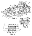
- gel pack 310 When a patient initially lies on body pad section 34, gel pack 310 will deform having viscous fluid 314 flow within casing 312 away from downwardly projecting portions of the patient that result in high interface pressure points between the patient and patient-support surface 56. This movement of viscous fluid 314 away from high interface pressure points and toward lower pressure interface points operates to increase the surface area of contact between the patient and patient-support surface as shown in Fig. 5.
- both pressure reduction foam layer 220 and high density foam layer 110 will deform in a like manner to minimize the interface pressure at high interface pressure points between the patient and patient-support surface 56.
- gaps 350 will typically still be found between the patient and the patient-support surface and relatively high interface pressure points will still exists between the patient and patient-support surface 56 as described below with reference to Figs. 13a, 13b, and 13c.
- support layer 110 and pressure reduction foam layer 220 are both made from a thermally active visco-elastic foam that is more pliable and more readily conforms to the shape of the patient at warmer temperatures than it does at cooler temperatures.
- the visco-elastic foam of support layer 110 and pressure reduction foam layer 220 cooperates with gel pack 310 to cause patient-support surface 56 to deform and move away from high interface pressure points between the patient and patient-support surface 56, thereby increasing the surface area of contact between the patient and patient-support surface 56 and reducing the interface pressure at high interface pressure points between the patient and patient-support surface 56, particularly when the patient first enters patient-support surface 56 and the temperature of patient-support surface 56 is warmer and enhancing the comfort of the patient.
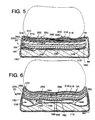
- bladders 146 of bladder pad 140 can be inflated as shown in Fig. 6.
- the inflation of bladders 146 operates to press patient-support surface 56 upwardly against the patient and into gaps 350 formed between the patient and patient-support surface 56, thereby minimizing the gaps therebetween.
- Minimizing gaps 350 between the patient and patient-support surface 56 maximizes the surface area of contact between the patient and patient-support surface 56, thereby evenly distributing the weight of the patient across patient-support surface 56 and minimizing the interface pressure of the highest remaining interface pressure points between the patient and patient-support surface 56.
- Maximizing the surface area of contact between the patient and patient-support surface 56 also maximizes the conductive heat transfer between the patient and patient-support surface 56.
- Inflating bladders 146 to press patient-support surface 56 against the patient and thereby more evenly distribute the weight of the patient across patient-support surface 56 also maximizes the efficacy of gel pack 310 as shown in Fig. 6.
- a top wall 316 of casing 312 is pressed against a bottom wall 318 of casing 312 at several locations indicating that additional relief of high interface pressure points is needed.
- Evenly distributing the weight of the patient across patient-support surface 56 by inflating bladders 146 also operates to more evenly distribute viscous fluid 314 across casing 312 of gel pack 310 to minimize the area of locations at which top wall 316 of casing 312 engages bottom wall 318 of casing 312. Minimizing the engagement between top wall 316 and bottom wall 318 maximizes the effectiveness of gel pack 310 and minimizes the interface pressure of the highest interface pressure points between the patient and patient-support surface 56.
- Inflating bladders 140 also causes pad core elements 92 positioned between bladder and 140 and patient-support surface 56, including vacuum bead bag 180, to conform to the shape of patient-support surface 56 as shown in Fig. 6. Once bladders 146 have been inflated, pushing patient-support surface 56 against the contours of the surface of the patient engaging patient-support surface 56 and filling gaps 350 that were initially formed between the patient and patient-support surface 56, the air can be evacuated from interior region 184 of casing 182 of vacuum bead bag 180.
- Evacuating the air from vacuum bead bag 180 causes casing 182 to compress and causes compressible beads 194 to compress against one another as shown best in Fig. 7. Compression of beads 194 against one another eliminates the ability of beads 194 to move with respect to one another thus causing vacuum bead bag 180 to rigidly assume the shape held by vacuum bead bag 180 when the air was evacuated from interior region 184 of casing 182. Vacuum bead bag 180 will thus rigidly retain the shape conforming to the shape of patient-support surface 56 shown in Fig. 6 so long as the air remains evacuated from vacuum bead bag 180.
- vacuum bead bag 180 to include lower layer 186 having a plurality of longitudinally-extending tubes 190 and upper layer 188 having a plurality of transversely extending elongated tubes 190 results in the plywood effect in which vacuum bead bag 180 provides a rigid support both in the longitudinal direction and in the transverse direction.
- bladders 146 can be deflated as shown in Fig. 8. Because vacuum bead bag 180 rigidly assumes the shape that it had immediately before air was evacuated from interior region 84, and because vacuum bead bag 180 is positioned to lie in interior region 88 of cover 86 on top of bladder pad 140 and bladders 146, deflating bladders 146 does not effect the conformal fit achieved between the patient and patient-support surface 56. However, by deflating bladders 146, the patient is more firmly and solidly supported than when the patient is resting on inflated bladders 146 which may act as resilient "balloons" allowing patient to vibrate or bounce.
- thermoregulation fluid circulates between channels 266 of thermal pads 260 and heat exchanger 372 which is carried in control housing 74.
- the temperature of the thermoregulation fluid and, thus, of thermal pad 260 and patient-support surface 56 is adjusted by adjusting the amount of heat added or removed from the thermoregulation fluid by heat exchanger 372.
- the control of heat exchanger 372 is described in more detail below with reference to Fig. 14.
- heat exchanger 372 is a so-called "Peltier device” for heating and cooling the thermal regulation fluid and contains no freon or other regulated chlorofluorocarbons (CFCs) or other ozone depleting chemicals.
- the thermoregulation fluid is water which circulates between the Peltier device and the channels 266 of thermal pads 260, although any generally inert fluid having suitable heat capacity and viscosity characteristics can be used as the thermoregulation fluid without exceeding the scope of the invention as presently perceived.
- thermocouple 382 is received in gel pack 310 and is carried within casing 312 along with viscous fluid 314.
- the thermocouple measures the temperature of viscous fluid 314 of gel pack 310 and provides a temperature input signal in response thereto.
- the temperature input signal is received by a controller 370 which is carried in control housing 74 as shown diagrammatically in Fig. 14. Controller 370 receives the temperature input signal and provides a heat exchange output signal in response to the temperature input signal.
- Heat exchanger 372 receives the head exchange output signal from the controller and adjusts the temperature of the thermoregulation fluid until the temperature input signal from the thermocouple indicates that the thermocouple has reached a desired temperature.
- the temperature input signal indicates the temperature of viscous fluid 314 in gel pack 310
- the proximity of gel pack 310 to patient-support surface 56 makes measurement of the temperature of gel pack 310 an adequate estimate of the temperature of patient-support surface 56 and the difference therebetween can be adequately compensated for by controller 370.
- surface pad system 20 may be manipulated to reposition the anesthetized patient after the surgical procedure has started. For example, when performing a Cesarean section, it is a common practice for the surgical team to place a roll, a wedge, or some other object under the left hip of the mother to shift the weight of the baby by moving the mother onto her right side. Rather than having members of the surgical team manually reposition the mother, surface pad system 20 in accordance with the present invention can include a second side bladder 158 positioned to lie on top of a first side bladder 160, both of which are appended to bladder pad 140 as shown in Fig. 9.
- a member of the surgical team may simply provide a user input from keypad 378 to controller 370 which will activate the source of pressurized fluid as well as valving of valve manifold 384 necessary to direct the pressurized fluid to first and second side bladders 158, 160 to inflate side bladders 158, 160 as shown in Fig. 9.
- Inflation of both side bladders 158, 160 operates to roll the patient to one side as shown in Fig. 9. It will be appreciated by those skilled in the art that using surface pad system 20 to reposition the patient is advantageous for the patient in that a more controlled repositioning can occur than when members of the surgical team manually reposition the patient.
- patient-support surface 56 grips the patient to firmly hold the patient in place relative to patient-support surface 56 and to prevent slipping of the patient with respect thereto during repositioning of the patient and patient-support surface 56.
- first and second side bladders 158, 160 may easily be deflated to reposition patient-support surface 56 to the generally horizonal position shown in Fig. 8.
- bladder pad 140 also includes a central support bladder 162 extending longitudinally beneath the spine of the patient on patient-support surface 56 as shown best in Figs. 10 and 12.
- Central support bladder 162 can be inflated to a first pressure as shown in Figs. 6 to press patient-support surface 56 against the patient to fill gaps 350 between the patient and patient-support surface 56 as described above.
- central support bladder 162 can be inflated to a second pressure which is greater than the first pressure to inflate central support bladder 162 sufficiently to press the spine of the patient upwardly and hyperextend the chest of the patient as shown in Fig. 10.
- surface pad system 20 to hyperextend the chest cavity of the patient on patient-support surface 56 for certain surgical procedures such as cardiovascular procedures is preferable to the current practice of placing a wedge, a rolled-up gel pack, a rolled-up towel, or other object beneath the anesthetized patient during the procedure.
- use of surface pad system 20 allows for a more controlled lowering of the patient by simply deflating central support bladder 162.
- Cover 86 can be formed to include first and second spaced-apart elongated pockets 338 positioned to lie adjacent to first side 38 of body pad section 34 and second side 40 of body pad section 34, respectively, as shown in Fig. 11.
- Pockets 338 can each contain bladders 340 which are not connected to bladder pad 140, but which can be inflated to tilt patient-support surface 56 as shown in Fig. 11. It is advantageous in certain surgical procedures to tilt table-top 22 of the surgical table. Bladders 340 are particularly useful during such procedures for "fine-tuning" the orientation of patient-support surface 56.
- Illustrative and preferred surface pad system 20 includes pad sections 30 containing bladder pads 140 having bladders 146 that are preferably configured and positioned to lie as shown in Fig. 12 (in phantom) relative to the patient on patient-support surface 56.
- surface pad system 20 includes first side bladders 160 positioned to lie on both sides of the patient, at least one second side bladder 158 positioned to lie above one of first side bladders 160, and central support bladder 162 supporting the spine of the patient.
- bladders 146 include a lumbar bladder 164 supporting the lumbar region of the patient's back, a sacrum bladder 166 supporting the sacrum of the patient, and three leg-support bladders 168, one of which is positioned to lie between the legs of the patient and the others of which are positioned to lie on the outsides of the legs of the patient.
- bladders 146 can include a generally "doughnut-shaped" bladder for supporting the head of the patient, the bladder being ring-shaped with an opening formed therein so that the lowermost portion of the head of the patient is adjacent to the opening to minimize the interface pressure against the patient's head as well as to stabilize the patient's head.
- FIG. 13a, 13b, and 13c are diagrammatic representations indicating the interface pressure between the patient and patient-support surface 56.
- Each diagram includes dots 380 the density of which indicates the magnitude of the interface pressure between the patient and patient-support surface 56.
- Portions in each of Figs. 13a, 13b, and 13c showing a high density of dots 380 indicate high interface pressures between the patient and patient-support surface 56 on those portions of patient-support surface 56.
- portions of Figs. 13a, 13b, and 13c showing a low density of dots 380 or no dots 380 indicates low interface pressures between the patient and patient-support surface 56 or even no interface pressure therebetween indicating that the patient does not engage those portions of patient-support surface 56.
- Fig. 13a The weight of a patient supported on a conventional surface cover for a surgical table is supported primarily by the head, shoulder blades, sacrum, and heels of the patient as shown diagrammatically in Fig. 13a.
- the above-noted portions of the patient are the downwardly extending extremities of the patient when resting on a conventional surface cover for a surgical table and, as a result, these extremities of the patient support most of the weight of the patient and experience the highest interface pressure between the patient and patient-support surface 56.
- Fig. 13a It can also be seen in Fig. 13a that several portions of the patient have low interface pressures against patient-support surface 56 and even no contact with patient-support surface 56 as indicated by portions of Fig. 13a having no dots 380 associated therewith.
- the weight of the patient is not evenly distributed across the conventional surface cover for a surgical table.
- high density foam layer 110 and pressure reduction foam layer 220 both of which are made of thermally active visco-elastic foam, cooperate with gel pack 310 to distribute the weight of the patient across patient-support surface 56 as shown diagrammatically in Fig. 13b.
- the high density of dots near the patient's head, shoulder blades, sacrum, and heels indicate that although the weight of the patient is more evenly distributed across patient-support surface 56 than is distributed with the conventional surface covering for a surgical table shown in Fig. 13a, there are still some relatively high interface pressure points between the patient and patient-support surface 56.
- inflating bladders 146 causes patient-support surface 56 to conformingly engage the patient and to maximize the surface area of engagement between the patient and patient-support surface 56, thereby minimizing the occurrence of high interface pressure points between the patient and patient-support surface 56 as shown diagrammatically in Fig. 13c.
- use of surface pad system 20 minimizes pressure ulcers, neuropathy, and other nerve disorders and damage to nerve bundles that can result from prolonged exposure to high interface pressures.
- surface pad system 20 allows the surgical team to manipulate and adjust the temperature of patient-support surface 56 and thus of the patient.
- Surface pad system 20 also allows for an automated and controlled positioning of the patient relative to table-top 22 of the surgical table while enhancing the stability of the patient during repositioning operations. Instead of having members of the surgical team manually repositioning the anesthetized patient and simultaneously trying to bolster the patient in the new position using wedges, pillows, or other objects that are shoved between the patient and the tops of conventional coverings, surface pad system 20 automatically and controllably repositions the patient when instructed to do so by a member of the surgical team simply by inflating or deflating bladders 146 as required.
- Use of internal bladders 146 to reposition the patient eliminates the need to use rolled-up towels, pillows, or other objects to support the patient in the new position.
- These objects, which are placed between the patient and patient-support surface 56 are typically thermal insulators, so that elimination of the use of these objects eliminates an impediment to the heat transfer between patient-support surface 56 and the patient.
- control housing 74 which contains the controller 370, the heat exchanger 372, the pressurized fluid source 374, vacuum source 376, and a valve manifold 384 as shown diagrammatically in Fig. 14.
- Controller 370 receives the user input signals from key pad 378 and the temperature input signal as described above from thermocouple 382 positioned in gel pack 310 of body pad section 34.
- controller 370 receives temperature input signals from thermocouples 382 positioned in gel packs 310 of each pad section 30 that include thermal pads 260.
- Controller 370 receives the user input signals and the temperature input signals and provides a heat exchange output signal to heat exchanger 372, a vacuum output signal to vacuum source 376, a pressurized fluid output signal to the pressurized fluid source 374, and a valve positioning signal to valve manifold 384 in response thereto.
- Heat exchanger 372 operates to heat and cool the circulating thermoregulation fluid in response to the heat exchanger output signal in order to maintain the temperature of thermocouples 382 at the desired temperature.
- channels 266 of thermal pads 260 of all pad sections 30 are coupled together and are in fluid communication with one another through thermoregulation fluid supply conduit 62 and thermoregulation fluid return conduit 64.
- thermoregulation fluid flows from heat exchanger 372, through each pad section 30 in series, then back to heat exchanger 372. Consequently, one heat exchanger 372 can control the temperature of thermal pads 260 of each pad section 30.
- Vacuum source 376 operates to evacuate the atmosphere from interior region 184 of vacuum bead bags 180 or to allow air or another generally inert gas to flow into interior region 184 of vacuum bead bag 80 through conduits 68 in response to the vacuum output signal from controller 370.
- interior regions 184 of vacuum bead bags 180 of all pad sections 30 are coupled together and are in fluid communication with one another through vacuum conduit 68.
- vacuum source 376 forcing compressible beads 194 to squeeze against each other and deform, thereby becoming immobile with respect to one another and forcing vacuum bead bag 180 to its rigid condition.
- the air flows from vacuum source 376, through conduit 68, to interior regions 184 allowing vacuum bead bags 180 to once again become pliable.
- Pressurized fluid source 374 operates to supply pressurized fluid to selected bladders 146 at a pressure in accordance with the pressurized output signal and the valve positioning signal from controller 370 or to allow pressurized fluid to escape from selected bladders 146 in response to the pressurized fluid output signal and the valve positioning signal from controller 370.
- valve manifold 384 includes a plurality of valves (not shown), including a valve (not shown) associated with each pressurized fluid conduit 60 which is associated with each bladder 146.
- pressurized fluid source 374 provides pressurized fluid to valve manifold 384 and the valve associated with the selected bladder 146 opens so that pressurized fluid can flow along conduit 66 associated with the selected bladder 146 to fill and inflate the selected bladder 146.
- pressurized fluid is removed from valve manifold 384 and the valve associated with the selected bladder opens so that pressurized fluid can flow along conduit 66 associated with the selected bladder 146 from the selected bladder 146 to valve manifold 384, thereby allowing the selected bladder 146 to deflate.
- valve manifold 384 allows surface pad system 20 to include only one source of pressurized fluid 374 to service all bladders 146 rather than requiring a separate source of pressurized fluid for each bladder 146.
- the preferred pressurized fluid is air, although any generally inert fluid such as nitrogen, water, or any other suitable liquid or gas can be used as the pressurized fluid to inflate bladders 146. It is therefore within the scope of the invention as presently perceived for the source of pressurized fluid to include an air or water tank, an air compressor, a "house” compressed air or other compressed gas line, a water line of a hospital or other facility, or any other suitable source of pressurized fluid.
- controller 370 Having each of vacuum bead bag 180, bladders 146, and thermal pad 260 controlled by controller 370 provides a convenient single source of information for data logging parameters such as the amount of time a patient spends in a single position, the amount of time a patient spends on surface pad system 20 and thus on table-top 22 of the surgical table, the amount of time the patient spends at a particular temperature, and other parameters related to the operation of surface pad system 20.
- controller 370 can coordinate the operation of bladders 146, vacuum bead bag 180, and thermal pad 260, for example, to control the sequence of operations such as providing that bladders 146 inflate before air is evacuated from interior region 184 of vacuum bead bag 180, providing that the air is evacuated from bladders 146 before the temperature of the patient is reduced for surgery, as well as providing computer control for such tasks as controlling the temperature of the patient and patient-support surface 56 for surgical procedures performed at reduced temperatures.
- controller 370 can also be programmed to automatically adjust bladders 146, vacuum bead bag 180, and thermal pad 260.
- illustrative surface pad system 20 includes head pad section 32, body pad section 34, leg pad section 36, first arm pad section 42, and second arm pad section 44
- the number of pad sections 30 and the arrangement of pad sections 30 can be varied.
- head pad section 32 can be eliminated from surface pad system 20 and can be replaced with a conventional head pad for a surgical surface such as a "doughnut-shaped" pad commonly used to support the head of a patient.
- surface pad system 20 can include an additional pad section (not shown) that is positioned to lie between body pad section 34 and leg pad section 36.
- pad sections 30 are removably coupled to one another so that each pad section 30 can operate independently of the other pad sections 30.
- Conduits 60 are provided with quick disconnect couplings 72 as shown in Fig. 1 to facilitate disconnecting one of pad sections 30 from another of pad sections 30 and reconnecting to yet another of pad sections 30 or to couplings 62 of hose 76.
- surface pad system 20 can be operated using body pad section 34, leg pad section 36, and arm pad sections 42, 44, having the head of the patient resting on a conventional pillow.
- surface pad system 20 can be operated using only body pad section 34 and leg pad section 36 with the head of the patient supported by a conventional pillow and the arms of the patient resting on table-top 22 or on top of the patient.
- the specific configuration or number of pad sections 30 of surface pad system 20 can be varied.
Landscapes
- Health & Medical Sciences (AREA)
- Life Sciences & Earth Sciences (AREA)
- Animal Behavior & Ethology (AREA)
- General Health & Medical Sciences (AREA)
- Public Health (AREA)
- Veterinary Medicine (AREA)
- Engineering & Computer Science (AREA)
- Biomedical Technology (AREA)
- Nursing (AREA)
- Accommodation For Nursing Or Treatment Tables (AREA)
Abstract
Description
Claims (48)
- A surface pad system for a surgical table, the surface pad system comprisinga cover having an upwardly-facing patient-support surface defining an interior region of the surface pad system,a vacuum bead bag received in the interior region, the vacuum bead bag including a flexible cover defining an interior region containing compressible beads, anda bladder received in the interior region of the cover and positioned to lie beneath the vacuum bead bag, the bladder defining an interior region and being inflatable when pressurized fluid is received in the interior region of the bladder so that the vacuum bead bag conformingly engages the patient on the patient-support surface when the bladder is inflated.
- The surface pad system of claim 1, wherein the vacuum bead bag includes a lower layer of compressible beads and an upper layer of compressible bead separated from the lower layer of compressible beads by a membrane made from a flexible material.
- The surface pad system of claim 2, wherein the membrane is formed to include a plurality of elongated tubes, each tube defining an interior region receiving compressible beads, each layer including a plurality of abutting parallel tubes.
- The surface pad system of claim 3, wherein the tubes comprising the upper layer extend in a transverse direction and the tubes comprising the lower layer extend in a longitudinal direction.
- The surface pad system of claim 3, wherein the tubes comprising the upper layer extend in a longitudinal direction and the tubes comprising the lower layer extend in a transverse direction.
- The surface pad system of claim 1, further comprising a bladder pad received in the interior region and including a top wall having an upper surface, a bottom wall and a fluid inlet port in fluid communication with a source of compressed fluid, the bladder being appended to the upper surface, and the bottom wall being formed to include a channel in fluid communication with the bladder and with the fluid inlet port so that fluid can be communicated from the source of compressed fluid to the bladder through the fluid inlet port and the channel to inflate the bladder.
- The surface pad system of claim 1, further comprising a thermal pad received in the interior region, the thermal pad including means for selecting and maintaining the temperature of the patient-support surface and being positioned to lie above the vacuum bead bag and the bladder.
- The surface pad system of claim 1, wherein the bladder is positioned to lie beneath the patient-support surface supporting the patient between the shoulder blades of the patient to minimize interface pressure between the shoulder blades of the patient and the patient-support surface when the bladder is inflated to a first pressure.
- The surface pad system of claim 8, wherein the bladder can be inflated to a second pressure which is greater than the first pressure and the bladder lifts the patient-support surface adjacent to the bladder sufficiently to hyperextend the chest of the patient when the bladder is inflated to the second pressure.
- The surface pad system of claim 1, wherein the bladder is an elongated longitudinally extending first bladder positioned to lie beneath the patient-support surface supporting the patient between the lower legs of the patient and further comprising elongated and longitudinally extending second and third bladders transversely spaced apart from each other and spaced apart from the first bladder, the first bladder being positioned to lie between the second and third bladders so that the first bladder cooperates with the second and third bladders to cradle the calves and heels of the patient when the first, second, and third bladders are inflated.
- The surface pad system of claim 1, wherein the bladder is positioned to lie beneath the patient-support surface supporting the sacral area of the patient to minimize the interface pressure between the sacrum of the patient and the patient-support surface.
- The surface pad system of claim 1, wherein the bladder is positioned to lie beneath the patient-support surface supporting the lumbar area of the patient to minimize the interface pressure between the patient-support surface and the upper back and sacrum of the patient.
- The surface pad system of claim 1, further comprising a controller coupled to the vacuum source for controlling the pressure in the interior region of the vacuum bead bag and a source of pressurized fluid in fluid communication with the bladder, the controller being coupled to the source of pressurized fluid for controlling the pressure in the interior region of the bladder so that the controller can coordinate the operation of the vacuum bead bag and the bladder.
- The surface pad system of claim 13, further comprising a thermal pad received in the interior region of the cover and a heat exchanger coupled to the thermal pad, the thermal pad including a channel in fluid communication with the heat exchanger and receiving thermoregulation fluid therefrom, the controller being coupled to the heat exchanger to control the temperature of the thermoregulation fluid, thus controlling the temperature of the patient-support surface.
- The surface pad system of claim 14, further comprising a gel layer received in the interior region and positioned to lie on top of the vacuum bead bag, the gel layer including a casing defining an interior region containing a viscous fluid, and a temperature sensor received in the interior region of the gel layer and coupled to the controller for providing an input signal to the controller in response to the temperature of the gel layer, the controller providing an output signal to the heat exchanger in response to the input signal, the heat exchanger controlling the temperature of the thermoregulation fluid in response to the output signal.
- A surface pad system for a surgical table, the surface pad system comprisinga head pad section having a top surface positioned to lie beneath the head of the patient,a leg pad section longitudinally spaced-apart from the head pad section and having a top surface positioned to lie beneath the lower legs and feet of the patient,a body pad section positioned to lie between the head pad section and the leg pad section and having a top surface positioned to lie beneath the torso and thighs of the patient, the body pad section having first and second spaced-apart elongated sides, andfirst and second arm pad sections, the first arm pad section being positioned to lie adjacent to the first side of the body pad section and the second arm pad section being positioned to lie adjacent to the second side of the body pad section, each of the first and second arm pad sections having a top surface, the top surfaces of the head section, leg section, body section, and first and second arm pad sections defining a generally planar patient-support surface.
- The surface pad system of claim 16, further comprising temperature means coupled to the body pad section for selecting and maintaining the temperature of the body pad section and the arm pad sections are coupled to the temperature means so that the temperature means also maintains the arm pad sections at the selected temperature.
- The surface pad system of claim 16, wherein the top surface of each arm pad section is curved so that the top surface of each arm pad section forms a longitudinally extending cradle positioned to lie between a pair of longitudinally extending upraised ridges, the cradle cooperating with the ridges to retain each arm of the patient on its respective arm pad section.
- The surface pad system of claim 16, wherein the body pad section includes a head end adjacent to the head section pad and each arm pad section includes a shoulder end adjacent to the head pad section and a finger end longitudinally spaced apart therefrom and the shoulder end of the first arm pad section is pivotably coupled to the first side of the body pad section adjacent to the head end and the second arm pad section is pivotably coupled to the second side of the body pad section adjacent to the head end so that each of the first and second arm pad sections can swing outwardly away from the body scion pad to provide greater access to the patient on the patient-support surface.
- The surface pad system of claim 16, wherein the body pad section and the leg pad section are each formed to include an interior region and further comprising a first thermal pad received in the interior region of the body pad section, the first thermal pad being formed to include a channel receiving thermoregulation fluid, a second thermal pad received in the interior region of the leg pad section, the second thermal pad being formed to include a channel receiving thermoregulation fluid, and the body pad section being coupled to the leg pad section having the channel of the first thermal pad in fluid communication with the channel of the second thermal pad so that the thermoregulation fluid circulates through both the body pad section and the leg pad section.
- The surface pad system of claim 20, wherein the first and second arm pad sections are each formed to include an interior region and further comprising a third thermal pad received in the interior region of the first arm pad section, the third thermal pad being formed to include a channel receiving thermoregulation fluid, and a fourth thermal pad received in the interior region of the second arm pad section, the fourth thermal pad being formed to include a channel receiving thermoregulation fluid, and the first and second arm pad sections are coupled to the body section pad having the channel of the third thermal pad in fluid communication with the channel of the first thermal pad and the channel of the fourth thermal pad in fluid communication with the channel of the first thermal pad so that the thermoregulation fluid circulates through the body pad section, the leg pad section, the first arm pad section, and the second arm pad section.
- The surface pad system of claim 20, further comprising a first vacuum bead bag having an interior region in fluid communication with a vacuum source and being received in the interior region of the body pad section and a second vacuum bead bag having an interior region in fluid communication with a vacuum source and being received in the interior region of the leg pad section, the body pad section being coupled to the leg pad section so that the interior region of the first vacuum bead bag is in fluid communication with the interior region of the second vacuum bead bag.
- A surface pad system for a surgical table, the surface pad system comprisinga cover defining an interior region, anda foam layer received in the interior region, the foam layer being made from a thermally active visco-elastic foam having a lower indention load deflection when the foam is warmer and a higher indention load deflection when the foam is cooler so that the surface pad system readily conforms to the patient at warmer temperatures and retains its shape at lower temperatures.
- The surface pad system of claim 23, wherein the foam layer is elongated and is formed to include an upwardly-facing top surface and the top surface is concave so that the foam layer and the cover cooperate to define longitudinally-extending spaced-apart ridges and a longitudinally-extending trough therebetween.
- The surface pad system of claim 23, further comprising a thermal pad received in the interior region and positioned to lie above the foam layer;
- A surface pad system for a surgical table, the surface pad system comprisinga pad core, anda cover defining an interior region receiving the pad core, the cover being made from a material that can stretch from a first length to a second length which is longer than the first length in a first direction and that can stretch from a third length to a fourth length which is longer than the third length in a second direction, the second direction being generally perpendicular to the first direction.
- The surface pad system of claim 26, wherein the cover is made from a material that is liquid impermeable to protect the pad core from liquids from outside of the surface pad system and to prevent the escape of liquids from the interior region of the cover.
- A surface pad system for supporting a patient above a surgical table, the surface pad system comprisinga pad having a core and a cover surrounding the core, anda needle receptacle fixed relative to the pad and positioned to lie adjacent to the pad, the needle receptacle including an outer shell that is formed to include an opening for receiving needles, the outer shell protecting the cover of the pad from penetration by a needle.
- The surface pad system of claim 28, wherein the surface pad system includes a head end adjacent to the head of the patient when the patient is supported by the surface pad system and the pad and the needle receptacle are positioned to lie adjacent to the head end of the surface pad system.
- A surface pad system for a surgical table, the surface pad system comprisinga pad core,a cover defining an interior region receiving the pad core, the cover having a top positioned to lie above the pad core, anda layer of cut-proof material positioned to lie between the pad core and the top of the cover so that the pad core is protected against penetration by sharp objects such as scalpels or needles that penetrate the top of the cover.
- The surface pad system of claim 30, wherein the top of the cover includes a parametrial edge and the cover includes generally vertically-extending sides appended to the parametrial edge of the top of the cover and extending downwardly therefrom and the layer of cut-proof material includes side portions positioned to lie between the pad core and the sides of the cover.
- A surface pad system for a surgical table, the surface pad system comprisinga body pad section having a head end, a foot end, and first and second spaced-apart sides therebetween, the body pad section being positioned to lie beneath the torso of the patient, the body pad section including a pad core and an outer cover defining an interior region receiving the pad core, the outer cover having a top and a bottom spaced-apart from the top and positioned to lie beneath the pad core, andan elongated bladder attached to the bottom of the cover and positioned to lie outside of the interior region of the outer cover, the bladder being positioned to lie adjacent to the first side and being inflatable between a deflated position in which the bottom of the cover is generally parallel to the surface of the surgical table and an inflated position in which the first side of the bottom cover is lifted above the surface of the surgical table so that the body pad section is tilted relative to the surface of the surgical table when the bladder is inflated.
- A surface pad system for a surgical table, the surface pad system comprisinga body pad section positioned to lie beneath the torso of the patient and including a pad core and a cover defining an interior region receiving the pad core, the pad core including a thermal pad having a casing defining a channel receiving thermoregulation fluid, anda leg pad section longitudinally spaced apart from the body pad section and positioned to lie beneath the lower legs and feet of the patient, the leg pad section being coupled to the body pad section and including a pad core and a cover defining an interior region receiving the pad core, the pad core including a thermal pad having a casing defining a channel receiving thermoregulation fluid, the channel of the thermal pad of the leg pad section being in fluid communication with the channel of the thermal pad of the body pad section so that thermoregulation fluid can pass therebetween.
- The surface pad system of claim 33, wherein the body pad section includes first and second spaced-apart sides and further comprising a first arm pad section adjacent to the first side of the body pad section and a second arm pad section adjacent to the second side of the body pad section, each of the first and second arm pad sections being coupled to the body pad section and including a pad core and a cover defining an interior region receiving the pad core, the pad core of each arm pad section including a thermal pad having a casing defining a channel receiving thermoregulation fluid, the channel of the thermal pad of each arm pad section being in fluid communication with the channel of the thermal pad of the body pad section and the channel of the thermal pad of the leg pad section so that thermoregulation fluid can pass therebetween.
- A surface pad system for a surgical table, the surface pad system comprisinga cover defining an interior region and including an upwardly-facing top positioned beneath the patient, anda pad core received in the interior region of the cover, the pad core including a bladder positioned to lie adjacent to the top of the cover, the bladder being inflatable to a first pressure to adjust the support and firmness characteristics of the surface pad system adjacent to the bladder so that the interface pressure of high interface pressure points between the patient and the patient-support surface is minimized.
- The surface pad system of claim 35, wherein the bladder is inflatable to a second pressure to adjust the position of the patient.
- The surface pad system of claim 35, wherein the bladder is a first bladder and further comprising a second bladder positioned to lie adjacent to the top of the cover, the second bladder being inflatable to adjust the support and firmness characteristics of the surface pad system adjacent to the second bladder, the second bladder being inflatable and deflatable independent of the first bladder.
- A surface pad system for a surgical table, the surface pad system comprisinga body pad section positioned to lie beneath the torso and the thighs of the patient, the body pad section including an upwardly-facing top surface and spaced-apart, elongated first and second sides, andlongitudinally extending first and second arm pad sections positioned to lie adjacent to the first and second sides of the body pad section and positioned to lie beneath the arms of the patient, each arm pad section including a top surface that is generally coplanar with the top surface of the body pad section.
- The surface pad system of claim 38, wherein the top surface of each arm pad section is concave to form a longitudinally-extending trough for cradling the arms of the patient, the trough being positioned to lie between first and second upwardly extending ridges and cooperating therewith to hold each arm of the patient on its respective arm rest.
- A surface pad system for a surgical table, the surface pad system comprisinga cover defining an interior region, a top having an upwardly-facing patient-support surface, and a bottom having a downwardly-facing bottom surface spaced apart from the patient-support surface,a high density foam first support layer received in the interior region and engaging the bottom of the cover,a bladder received in the interior region and engaging the first support layer,a lower layer of positioning beads received in the interior region and engaging the bladder, the lower layer of positioning beads including a plurality of transversely extending elongated tubes made from a flexible material, each tube defining an interior region receiving beads,an upper layer of positioning beads received in the interior region and engaging the lower layer of positioning beads, the upper layer of positioning beads including a plurality of longitudinally extending elongated tubes made from a flexible material, each tube defining an interior region receiving beads,a high density foam second support layer received in the interior region and engaging the upper layer of positioning beads,a thermal pad received in the interior region and engaging the second support layer, the thermal pad including a casing defining a serpentine channel receiving a thermoregulation fluid at a selected temperature,a gel layer received in the interior region and engaging the thermal pad, the gel layer including a casing defining an interior region containing a viscous fluid, anda cut-proof material layered between the gel layer and the top of the cover to prevent the penetration of the gel layer by objects that penetrate the top of the cover.
- The surface pad system of claim 40, wherein the bottom of the cover includes first and second spaced-apart longitudinal sides and the cover is formed to include a pocket positioned to lie adjacent to the first side beneath the bottom of the cover, the pocket defining a pocket interior, and further comprising a bladder received by the pocket, the bladder being inflatable and deflatable to move the operating surface from a generally horizontal position when the bladder is deflated to a tilted position when the bladder is inflated.
- The surface pad system of claim 40, further comprising a heat exchanger regulating the temperature of thermoregulation fluid provided to the channel of the thermal pad, a vacuum source for evacuating air from the upper and lower layers of positioning beads, a pressurized air source for providing pressurized fluid to the bladder, and a controller for controlling and coordinating the operation of the heat exchanger, the vacuum source, and the pressurized fluid source.
- The surface pad system of claim 40, wherein the cover is made from a bi-directional stretch material that is stretchable both transversely and longitudinally so that the cover stretches instead of folding when the cover moves.
- A vacuum bead bag for use in a surface pad system for a surgical table, the vacuum bead bag comprisinga casing having an interior region,a plurality of elongated flexible tubes received in the interior region of the casing, each tube defining an interior region of the tube, anda plurality of compressible beads, each tube receiving beads of the plurality of compressible beads in the interior region of each tube,wherein a first set of tubes of the plurality of tubes includes tubes extending in a first direction and a second set of tubes of the plurality of tubes is positioned to lie above the first set of tubes, the second set of tubes including tubes extending in a second direction, the second direction being generally perpendicular to the first direction.
- A bladder pad for use in a surface pad system for a surgical table, the bladder pad comprisinga sheet having a first surface facing a first direction and a second surface facing a second direction which is opposite the first direction, the sheet being formed to include an opening extending therethrough,a bladder appended to the first surface and being formed to include an interior region and an opening in fluid communication with both the interior region of the bladder and the opening formed in the sheet, anda second sheet appended to the second surface of the first sheet and cooperating therewith to define a channel for receiving pressurized fluid, the channel being formed to include an opening in fluid communication with the opening of the sheet so that the channel is in fluid communication with the channel and the interior region of the bladder.
- A control system for use with a surface pad system for a surgical table, the control system comprisinga keypad for providing a user temperature input signal, a user vacuum input signal, and a user bladder input signal in response to user inputs,heat exchanger means for maintaining the temperature of a thermoregulation fluid at a predetermined temperature in response to a heat exchanger output signal,vacuum means for evacuating air from and replacing air into a chamber in fluid communication with the vacuum means in response to a vacuum output signal,pressurized fluid means for providing pressurized fluid to and evacuating pressurized fluid from a bladder in fluid communication with the pressurized fluid means in response to a pressurized fluid output signal, anda controller coupled to the keypad, the heat exchanger means, the vacuum means, and the pressurized fluid means, the controller including temperature means for providing the heat exchanger output signal to the heat exchanger means in response to the user temperature input signal, means for providing the vacuum output signal to the vacuum means in response to the user vacuum input signal, and means for providing the pressurized fluid output signal to the pressurized fluid means in response to the user bladder input signal.
- The control system of claim 46, further comprising a thermocouple coupled to the controller and providing a fluid temperature signal in response to the temperature of the thermocouple, the temperature means of the controller providing the heat exchanger output signal in response to the fluid temperature signal and the user temperature input signal.
- The control system of claim 46, wherein the keypad is movable relative to the controller.
Priority Applications (1)
| Application Number | Priority Date | Filing Date | Title |
|---|---|---|---|
| EP02078044A EP1323402A3 (en) | 1996-08-02 | 1997-07-31 | Surface pad system for a surgical table |
Applications Claiming Priority (2)
| Application Number | Priority Date | Filing Date | Title |
|---|---|---|---|
| US691573 | 1996-08-02 | ||
| US08/691,573 US5966763A (en) | 1996-08-02 | 1996-08-02 | Surface pad system for a surgical table |
Related Child Applications (1)
| Application Number | Title | Priority Date | Filing Date |
|---|---|---|---|
| EP02078044A Division EP1323402A3 (en) | 1996-08-02 | 1997-07-31 | Surface pad system for a surgical table |
Publications (3)
| Publication Number | Publication Date |
|---|---|
| EP0821928A2 true EP0821928A2 (en) | 1998-02-04 |
| EP0821928A3 EP0821928A3 (en) | 1998-06-10 |
| EP0821928B1 EP0821928B1 (en) | 2003-02-19 |
Family
ID=24777082
Family Applications (2)
| Application Number | Title | Priority Date | Filing Date |
|---|---|---|---|
| EP97305752A Expired - Lifetime EP0821928B1 (en) | 1996-08-02 | 1997-07-31 | Surface pad system for a surgical table |
| EP02078044A Withdrawn EP1323402A3 (en) | 1996-08-02 | 1997-07-31 | Surface pad system for a surgical table |
Family Applications After (1)
| Application Number | Title | Priority Date | Filing Date |
|---|---|---|---|
| EP02078044A Withdrawn EP1323402A3 (en) | 1996-08-02 | 1997-07-31 | Surface pad system for a surgical table |
Country Status (11)
| Country | Link |
|---|---|
| US (5) | US5966763A (en) |
| EP (2) | EP0821928B1 (en) |
| JP (1) | JPH1099387A (en) |
| KR (1) | KR19980018312A (en) |
| AR (1) | AR008798A1 (en) |
| AT (1) | ATE232712T1 (en) |
| AU (1) | AU730703B2 (en) |
| BR (1) | BR9706873A (en) |
| CA (1) | CA2212068A1 (en) |
| DE (1) | DE69719125T2 (en) |
| TW (1) | TW343919B (en) |
Cited By (16)
| Publication number | Priority date | Publication date | Assignee | Title |
|---|---|---|---|---|
| WO1999023980A1 (en) * | 1997-11-07 | 1999-05-20 | Hill-Rom, Inc. | Patient thermal regulation system |
| WO1999023992A1 (en) * | 1997-11-07 | 1999-05-20 | Hill-Rom, Inc. | Surgical table |
| WO2000013643A1 (en) * | 1998-09-03 | 2000-03-16 | Alain Wetterwald | Shell for automatically positioning a patient safely |
| US6484334B1 (en) | 1997-11-07 | 2002-11-26 | Hill-Rom Services, Inc. | Surgical table |
| EP1265672A1 (en) * | 2001-01-31 | 2002-12-18 | Megadyne Medical Products, Inc. | Pressure sore pad having self-limiting electrosurgical return electrode properties and optional heating/cooling capabilities |
| WO2004098481A3 (en) * | 2003-05-05 | 2005-04-21 | Cleveland Clinic Foundation | Patient support apparatus having an air cell grid and associated method |
| WO2007100991A2 (en) * | 2006-02-24 | 2007-09-07 | Escaross Essam B | System and method for adjusting pressure in pockets or zones |
| DE102011001224A1 (en) | 2011-03-11 | 2012-09-13 | Bernd Lühring | Treatment table for chiropractic treatments, has multiple segments that are independent from each other and are lowered from elevated working position into lowered idle position |
| US8499503B2 (en) | 2001-05-25 | 2013-08-06 | Hill-Rom Services, Inc. | Thermoregulation equipment for patient room |
| WO2013182348A1 (en) * | 2012-06-07 | 2013-12-12 | Pearltec Ag | Positioning and support system |
| US9021640B2 (en) | 2012-11-27 | 2015-05-05 | Marion Mohr | Vacuum mattress |
| EP3038584A1 (en) * | 2014-09-04 | 2016-07-06 | William Purdy | System and method for off-loading of the body in the prone position and for patient turning and repositioning |
| US10596051B2 (en) | 2011-06-09 | 2020-03-24 | Molnlycke Health Care Ab | System and method for patient turning and repositioning with simultaneous off-loading of the body in the prone position |
| EP3632392A3 (en) * | 2016-11-08 | 2020-07-22 | Optimus Licensing AG | Integrated operating room lighting and patient warming system - design and components |
| EP3689316A1 (en) * | 2019-01-29 | 2020-08-05 | TRUMPF Medizin Systeme GmbH + Co. KG | System comprising an operating table, an air bladder, and an air compressor |
| US10925790B2 (en) | 2011-06-09 | 2021-02-23 | Mölnlycke Health Care Ab | System and method for patient turning and repositioning |
Families Citing this family (249)
| Publication number | Priority date | Publication date | Assignee | Title |
|---|---|---|---|---|
| US6115861A (en) * | 1997-10-09 | 2000-09-12 | Patmark Company, Inc. | Mattress structure |
| US5966763A (en) | 1996-08-02 | 1999-10-19 | Hill-Rom, Inc. | Surface pad system for a surgical table |
| EP1024733B1 (en) * | 1997-10-24 | 2003-01-15 | Hill-Rom Services, Inc. | Mattress having air fluidized sections |
| US7191482B2 (en) * | 1998-05-06 | 2007-03-20 | Hill Rom Services, Inc. | Patient support |
| EP1457139A1 (en) | 1998-05-06 | 2004-09-15 | Hill-Rom Services, Inc. | Mattress or cushion structure |
| US9462893B2 (en) | 1998-05-06 | 2016-10-11 | Hill-Rom Services, Inc. | Cover system for a patient support surface |
| WO2000000117A1 (en) | 1998-06-26 | 2000-01-06 | Hill-Rom, Inc. | Heated patient support apparatus |
| US6447865B1 (en) | 1998-07-22 | 2002-09-10 | Gaymar Industries, Inc. | Gelatinous composite article and construction |
| DE19845730B4 (en) * | 1998-10-05 | 2005-02-10 | Audi Ag | cushion support |
| US6780352B2 (en) | 1999-01-11 | 2004-08-24 | 2Phase Technologies, Inc. | Use of state-change materials in reformable shapes, templates or tooling |
| US7172714B2 (en) * | 1999-01-11 | 2007-02-06 | 2Phase Technologies, Inc. | Use of state-change materials in reformable shapes, templates or tooling |
| US6398992B1 (en) * | 1999-01-11 | 2002-06-04 | Theodore L. Jacobson | Use of state-change materials in reformable shapes templates or tooling |
| US6606754B1 (en) * | 1999-03-30 | 2003-08-19 | Gaymar Industries, Inc. | Supported hypo/hyperthermia pad |
| US6370716B1 (en) * | 1999-04-20 | 2002-04-16 | John W. Wilkinson | Inflatable cushioning device with tilting apparatus |
| US6578219B1 (en) * | 1999-05-26 | 2003-06-17 | Kci Licensing, Inc. | Mattress overlay for operating room table |
| US6800087B2 (en) * | 2000-01-07 | 2004-10-05 | The Cleveland Clinic Foundation | Blanket system for temperature regulation of a patient |
| TW454890U (en) * | 2000-01-26 | 2001-09-11 | Jou Jian Fa | Computer wrist pad with adjustable height and hardness |
| EP1257241A2 (en) | 2000-02-25 | 2002-11-20 | Hill-Rom Services, Inc. | Air fluidized bladders for a bed |
| US6516483B1 (en) * | 2000-03-28 | 2003-02-11 | The Or Group, Inc. | Patient support surface |
| AU2001290951A1 (en) * | 2000-09-14 | 2002-03-26 | Alan J. Soucy | Vibration dampening apparatus |
| WO2002038099A2 (en) * | 2000-11-07 | 2002-05-16 | Tempur World, Inc. | Therapeutic mattress assembly |
| US20020144343A1 (en) * | 2000-12-08 | 2002-10-10 | Kuiper Hendrik Klaas | Portable patient turning and lifting device |
| US6598251B2 (en) | 2001-06-15 | 2003-07-29 | Hon Technology Inc. | Body support system |
| US6681427B2 (en) | 2001-06-19 | 2004-01-27 | Anderson Bio-Bed, Incorporated | Apparatus for imparting continuous motion to a mattress |
| US6721977B2 (en) * | 2001-08-03 | 2004-04-20 | Angela Solesbee | Medical procedure table pad |
| US6855158B2 (en) | 2001-09-11 | 2005-02-15 | Hill-Rom Services, Inc. | Thermo-regulating patient support structure |
| US7172616B2 (en) * | 2002-01-17 | 2007-02-06 | Nellcor Puritan Bennett Inc. | Inflatable blanket for use in cardiac surgery |
| US6859967B2 (en) | 2002-02-22 | 2005-03-01 | Samuel W. Harrison | Overlay mattress |
| US20030175473A1 (en) * | 2002-03-14 | 2003-09-18 | Timothy Gillum | Surgical table pad with fluid waste channel |
| JP2003265276A (en) * | 2002-03-18 | 2003-09-24 | Honda Access Corp | Body support bag |
| WO2003095018A2 (en) * | 2002-05-09 | 2003-11-20 | Daemen College | Electrical stimulation unit and waterbath system |
| US7051389B2 (en) | 2002-05-24 | 2006-05-30 | Tempur World, Llc | Comfort pillow |
| US7080422B2 (en) * | 2002-06-08 | 2006-07-25 | Michael Ben-Levi | Automatic patient turner |
| US20050166328A1 (en) * | 2002-06-08 | 2005-08-04 | Tumamatic Foundation | Automatic patient turner |
| US6893086B2 (en) * | 2002-07-03 | 2005-05-17 | W.E.T. Automotive Systems Ltd. | Automotive vehicle seat insert |
| US7666213B2 (en) * | 2002-07-11 | 2010-02-23 | Life Recovery Systems Hd, Llc | Apparatus for altering the body temperature of a patient |
| US7547320B2 (en) * | 2002-07-11 | 2009-06-16 | Life Recovery System Hd, Llc | Apparatus for altering the body temperature of a patient |
| US6969399B2 (en) * | 2002-07-11 | 2005-11-29 | Life Recovery Systems Hd, Llc | Apparatus for altering the body temperature of a patient |
| US6726753B2 (en) * | 2002-07-30 | 2004-04-27 | Honeywell International Inc. | Coated carbon brake disc materials |
| US6857697B2 (en) * | 2002-08-29 | 2005-02-22 | W.E.T. Automotive Systems Ag | Automotive vehicle seating comfort system |
| ES2507642T3 (en) * | 2002-10-15 | 2014-10-15 | Verance Corporation | Media supervision, management and information system |
| DE10259648B4 (en) * | 2002-12-18 | 2006-01-26 | W.E.T. Automotive Systems Ag | Air-conditioned seat and air conditioning device for a ventilated seat |
| US6883193B2 (en) * | 2003-03-05 | 2005-04-26 | Xymid, L.L.C. | Elastic fitted cover |
| US7107642B2 (en) * | 2003-03-12 | 2006-09-19 | Jetta Company Limited | Adjustable mattress and pillow system |
| US8182521B2 (en) * | 2003-09-24 | 2012-05-22 | Dynatherm Medical Inc. | Methods and apparatus for increasing blood circulation |
| US7356912B2 (en) * | 2003-09-25 | 2008-04-15 | W.E.T. Automotive Systems, Ltd. | Method for ventilating a seat |
| US7274007B2 (en) * | 2003-09-25 | 2007-09-25 | W.E.T. Automotive Systems Ltd. | Control system for operating automotive vehicle components |
| US7155765B2 (en) | 2003-10-14 | 2007-01-02 | Tempur World, Llc | Pillow top for a cushion |
| US7370911B2 (en) * | 2003-10-17 | 2008-05-13 | W.E.T. Automotive Systems, Ag | Automotive vehicle seat insert |
| US7425034B2 (en) * | 2003-10-17 | 2008-09-16 | W.E.T. Automotive Systems Ag | Automotive vehicle seat having a comfort system |
| US7004412B2 (en) * | 2003-11-20 | 2006-02-28 | Carter Day International, Inc. | Micron hammermill |
| US7461892B2 (en) | 2003-12-01 | 2008-12-09 | W.E.T. Automotive Systems, A.C. | Valve layer for a seat |
| US7871387B2 (en) | 2004-02-23 | 2011-01-18 | Tyco Healthcare Group Lp | Compression sleeve convertible in length |
| US7469436B2 (en) | 2004-04-30 | 2008-12-30 | Hill-Rom Services, Inc. | Pressure relief surface |
| EP2250988A3 (en) | 2004-04-30 | 2011-11-30 | Hill-Rom Services, Inc. | Patient support with motion monitor device |
| US7887386B2 (en) * | 2004-06-29 | 2011-02-15 | Sun Yu | Sensory stimulation plush |
| CN1739421A (en) * | 2004-08-27 | 2006-03-01 | 叶永丰 | Air-cushion bed |
| US7377935B2 (en) * | 2004-09-24 | 2008-05-27 | Life Recovery Systems Hd, Llc | Apparatus for altering the body temperature of a patient |
| US20060158011A1 (en) * | 2004-11-02 | 2006-07-20 | W.E.T. Automotive Systems Ag | Molded layer for a seat insert |
| US20060117482A1 (en) * | 2004-12-07 | 2006-06-08 | Branson Gregory W | Touch screen control for lateral rotation of a hospital bed mattress |
| DE102005018445B3 (en) * | 2005-04-20 | 2006-06-29 | W.E.T. Automotive Systems Ag | Air conditioning device for e.g. vehicle seat has air-conditioning zones, which are connected to recess by connecting device whereby recess allows the air to pass through it partially in transverse direction inspite of cover |
| US7219380B2 (en) * | 2005-04-22 | 2007-05-22 | R&D Products, Llc | Multicompartmented air mattress |
| US7469437B2 (en) | 2005-06-24 | 2008-12-30 | Tempur-Pedic Management, Inc. | Reticulated material body support and method |
| AU2006269277B2 (en) | 2005-07-08 | 2012-02-16 | Hill-Rom, Inc. | Patient support |
| JP5231222B2 (en) | 2005-07-08 | 2013-07-10 | ヒル−ロム サービシーズ,インコーポレイティド | Patient support control unit |
| GB0515294D0 (en) | 2005-07-26 | 2005-08-31 | Novamedix Distrib Ltd | Limited durability closure means for an inflatable medical garment |
| US7546650B2 (en) * | 2005-07-28 | 2009-06-16 | Yale University | Adjustable surgical table |
| US6990701B1 (en) * | 2005-08-05 | 2006-01-31 | Vera Litvak | Sectional non-slip mattress |
| US7478869B2 (en) * | 2005-08-19 | 2009-01-20 | W.E.T. Automotive Systems, Ag | Automotive vehicle seat insert |
| WO2007047379A2 (en) * | 2005-10-12 | 2007-04-26 | Sundance Enterprises | Fluidized positioning and protection system |
| US7287289B1 (en) * | 2005-11-01 | 2007-10-30 | Mark Hagopian | Surgical table having low pressure anti decubitus ulcer surface |
| US8191288B2 (en) * | 2005-11-03 | 2012-06-05 | Pro-Tech Manufacturing And Distribution, Inc. | Reversible snow pusher and coupler |
| US20070118993A1 (en) * | 2005-11-28 | 2007-05-31 | Jason Bates | Inflatable incontinence bed pad |
| US7442175B2 (en) * | 2005-12-12 | 2008-10-28 | Tyco Healthcare Group Lp | Compression sleeve having air conduit |
| US8029451B2 (en) | 2005-12-12 | 2011-10-04 | Tyco Healthcare Group Lp | Compression sleeve having air conduits |
| US20090312676A1 (en) * | 2006-02-02 | 2009-12-17 | Tylerton International Inc. | Metabolic Sink |
| US20080033518A1 (en) * | 2006-02-02 | 2008-02-07 | Tylerton International Inc. | Thermoregulating units |
| US7854754B2 (en) * | 2006-02-22 | 2010-12-21 | Zeltiq Aesthetics, Inc. | Cooling device for removing heat from subcutaneous lipid-rich cells |
| JP2007236869A (en) * | 2006-03-13 | 2007-09-20 | Osada Res Inst Ltd | Chair for dental treatment |
| US8656537B2 (en) | 2006-04-20 | 2014-02-25 | Dan Foam Aps | Multi-component pillow and method of manufacturing and assembling same |
| US7774879B2 (en) * | 2006-05-23 | 2010-08-17 | Siemens Medical Solutions Usa, Inc. | Pillow for a patient during a medical procedure |
| US7771461B2 (en) | 2006-08-24 | 2010-08-10 | Life Recovery Systems Hd, Llc | Apparatus for altering the body temperature of a patient |
| US8192474B2 (en) * | 2006-09-26 | 2012-06-05 | Zeltiq Aesthetics, Inc. | Tissue treatment methods |
| US9132031B2 (en) | 2006-09-26 | 2015-09-15 | Zeltiq Aesthetics, Inc. | Cooling device having a plurality of controllable cooling elements to provide a predetermined cooling profile |
| KR20080029027A (en) * | 2006-09-28 | 2008-04-03 | 주경원 | Body fixing apparatus using vaccuum |
| DE102007027828A1 (en) * | 2006-11-14 | 2008-05-15 | Proseat Gmbh & Co.Kg | Module for cushioned object e.g. vehicle seat, has switching device partially corresponding with switching device of bolster unit, and cover covering bolster unit, where module and/or component part are foamed in carrier |
| US8607387B2 (en) * | 2006-11-20 | 2013-12-17 | Stryker Corporation | Multi-walled gelastic mattress system |
| US20080221493A1 (en) * | 2006-12-07 | 2008-09-11 | Life Recovery Systems Hd, Llc | Apparatus for altering the body temperature of a patient and administering decompression to the patients torso |
| WO2008070849A2 (en) | 2006-12-07 | 2008-06-12 | Life Recovery Systems Hd, Llc | Apparatus for altering the body temperature of a patient |
| GB2447287B (en) * | 2007-03-08 | 2011-11-23 | Anne Kathleen Paton | Personal temperature control device |
| US8283602B2 (en) | 2007-03-19 | 2012-10-09 | Augustine Temperature Management LLC | Heating blanket |
| US10201935B2 (en) | 2007-03-19 | 2019-02-12 | Augustine Temperature Management LLC | Electric heating pad |
| US20150366367A1 (en) | 2007-03-19 | 2015-12-24 | Augustine Temperature Management LLC | Electric heating pad with electrosurgical grounding |
| US8029450B2 (en) | 2007-04-09 | 2011-10-04 | Tyco Healthcare Group Lp | Breathable compression device |
| US8109892B2 (en) | 2007-04-09 | 2012-02-07 | Tyco Healthcare Group Lp | Methods of making compression device with improved evaporation |
| US8128584B2 (en) | 2007-04-09 | 2012-03-06 | Tyco Healthcare Group Lp | Compression device with S-shaped bladder |
| US8016778B2 (en) | 2007-04-09 | 2011-09-13 | Tyco Healthcare Group Lp | Compression device with improved moisture evaporation |
| US8070699B2 (en) | 2007-04-09 | 2011-12-06 | Tyco Healthcare Group Lp | Method of making compression sleeve with structural support features |
| US8021388B2 (en) | 2007-04-09 | 2011-09-20 | Tyco Healthcare Group Lp | Compression device with improved moisture evaporation |
| US8034007B2 (en) | 2007-04-09 | 2011-10-11 | Tyco Healthcare Group Lp | Compression device with structural support features |
| US8162861B2 (en) | 2007-04-09 | 2012-04-24 | Tyco Healthcare Group Lp | Compression device with strategic weld construction |
| US8506508B2 (en) | 2007-04-09 | 2013-08-13 | Covidien Lp | Compression device having weld seam moisture transfer |
| USD608006S1 (en) | 2007-04-09 | 2010-01-12 | Tyco Healthcare Group Lp | Compression device |
| US8016779B2 (en) | 2007-04-09 | 2011-09-13 | Tyco Healthcare Group Lp | Compression device having cooling capability |
| US7712171B2 (en) * | 2007-04-25 | 2010-05-11 | Hill-Rom Services, Inc. | Patient support including turn assist, low air loss, or integrated lateral transfer |
| US20080263772A1 (en) * | 2007-04-30 | 2008-10-30 | Li-Ya Chiu | Adjustable pad according user's weight |
| US20080263776A1 (en) * | 2007-04-30 | 2008-10-30 | Span-America Medical Systems, Inc. | Low air loss moisture control mattress overlay |
| US7954186B2 (en) * | 2007-05-04 | 2011-06-07 | Gaymar Industries, Inc. | Inflatable mattress with uniform restraint |
| US20080287839A1 (en) | 2007-05-18 | 2008-11-20 | Juniper Medical, Inc. | Method of enhanced removal of heat from subcutaneous lipid-rich cells and treatment apparatus having an actuator |
| US8523927B2 (en) * | 2007-07-13 | 2013-09-03 | Zeltiq Aesthetics, Inc. | System for treating lipid-rich regions |
| ES2693430T3 (en) | 2007-08-21 | 2018-12-11 | Zeltiq Aesthetics, Inc. | Monitoring of cooling of lipid-rich subcutaneous cells, such as cooling of adipose tissue |
| US8347436B2 (en) * | 2007-10-31 | 2013-01-08 | Stryker Corporation | Adaptable mattress conversion |
| US20090144903A1 (en) * | 2007-12-06 | 2009-06-11 | Delvaux Andrew B | Cpr facilitating mattress |
| US10531859B2 (en) | 2008-01-02 | 2020-01-14 | Arcscan, Inc. | Components for a precision ultrasonic scanning apparatus for body parts |
| US8758252B2 (en) * | 2008-01-02 | 2014-06-24 | Arcscan, Inc. | Innovative components for an ultrasonic arc scanning apparatus |
| US8549684B2 (en) * | 2008-03-25 | 2013-10-08 | Stryker Corporation | Gelastic material having variable or same hardness and balanced, independent buckling in a mattress system |
| US8496588B2 (en) * | 2008-04-03 | 2013-07-30 | Arcscan, Inc. | Procedures for an ultrasonic arc scanning apparatus |
| US8114117B2 (en) | 2008-09-30 | 2012-02-14 | Tyco Healthcare Group Lp | Compression device with wear area |
| CN101584631B (en) * | 2008-05-23 | 2011-04-20 | 北京航天长峰股份有限公司 | Three-section cover of operation table |
| EP2299912A4 (en) * | 2008-05-29 | 2013-01-23 | Arcscan Inc | Compound scanning head for an ultrasonic scanning apparatus |
| WO2010024933A2 (en) * | 2008-08-29 | 2010-03-04 | Miriam Mackovic-Basic | Surgeon lift system |
| US20100058538A1 (en) * | 2008-09-09 | 2010-03-11 | Michael Rieber | Baby headrest |
| US9167921B2 (en) | 2008-09-09 | 2015-10-27 | Michael Rieber | Baby headrest |
| US8495774B2 (en) | 2008-09-12 | 2013-07-30 | Piedmont 361, Llc | Hospital chair beds with articulating foot sections |
| US8235923B2 (en) | 2008-09-30 | 2012-08-07 | Tyco Healthcare Group Lp | Compression device with removable portion |
| EP2348978B1 (en) * | 2008-10-03 | 2017-12-06 | HLZ Innovation, Llc | Adjustable pneumatic supporting surface |
| US8264342B2 (en) | 2008-10-28 | 2012-09-11 | RF Surgical Systems, Inc | Method and apparatus to detect transponder tagged objects, for example during medical procedures |
| WO2010068797A1 (en) * | 2008-12-10 | 2010-06-17 | Waverx, Inc. | Devices, systems and methods for preventing and treating sensation loss |
| US9149254B2 (en) | 2008-12-15 | 2015-10-06 | Arcscan, Inc. | Alignment and imaging of an eye with an ultrasonic scanner |
| EP2379039B1 (en) * | 2008-12-17 | 2016-02-17 | Stryker Corporation | Patient support |
| US8603073B2 (en) * | 2008-12-17 | 2013-12-10 | Zeltiq Aesthetics, Inc. | Systems and methods with interrupt/resume capabilities for treating subcutaneous lipid-rich cells |
| DE202009017046U1 (en) | 2008-12-21 | 2010-05-12 | W.E.T. Automotive Systems Ag | aerator |
| US9119479B2 (en) | 2008-12-22 | 2015-09-01 | Tempur-Pedic Management, Llc | Adjustable-firmness body support and method |
| WO2010075291A1 (en) * | 2008-12-23 | 2010-07-01 | Tempur-Pedic Management, Inc. | Adjustable-firmness body support and method |
| US8876812B2 (en) * | 2009-02-26 | 2014-11-04 | Megadyne Medical Products, Inc. | Self-limiting electrosurgical return electrode with pressure sore reduction and heating capabilities |
| WO2010127315A2 (en) | 2009-04-30 | 2010-11-04 | Zeltiq Aesthetics, Inc. | Device, system and method of removing heat from subcutaneous lipid-rich cells |
| US8590075B1 (en) * | 2009-06-09 | 2013-11-26 | Ibrahim H. Amjad | Mattress assembly for newborn infants |
| US9792408B2 (en) | 2009-07-02 | 2017-10-17 | Covidien Lp | Method and apparatus to detect transponder tagged objects and to communicate with medical telemetry devices, for example during medical procedures |
| US8690807B2 (en) | 2009-09-02 | 2014-04-08 | Allen Medical Systems, Inc. | Surgical positioning system |
| US8510883B2 (en) * | 2009-10-30 | 2013-08-20 | Arcscan, Inc. | Method of positioning a patient for medical procedures |
| US9420895B2 (en) * | 2009-12-17 | 2016-08-23 | Stryker Corporation | Patient support |
| DE102009059995A1 (en) * | 2009-12-21 | 2011-06-22 | W.E.T. Automotive Systems AG, 85235 | Electric heater |
| US20110190855A1 (en) * | 2009-12-23 | 2011-08-04 | Michael Amalfi | Cooling Assembly |
| KR20120113788A (en) * | 2010-01-25 | 2012-10-15 | 젤티크 애스세틱스, 인코포레이티드. | Home-use applicators for non-invasively removing heat from subcutaneous lipid-rich cells via phase change coolants, and associated devices, systems and methods |
| WO2011097569A2 (en) * | 2010-02-05 | 2011-08-11 | Stryker Corporation | Patient/invalid handling support |
| US8652079B2 (en) | 2010-04-02 | 2014-02-18 | Covidien Lp | Compression garment having an extension |
| DE102011014516A1 (en) | 2010-04-06 | 2012-05-10 | W.E.T. Automotive Systems Ag | MFP |
| US8863338B2 (en) | 2010-06-02 | 2014-10-21 | Touchsensor Technologies, Llc | Therapeutic support device allowing capillary blood flow |
| RU2445948C2 (en) * | 2010-06-04 | 2012-03-27 | Владимир Петрович Орлов | Device for functional lumbar flexion accompanying structural surgeries |
| US8676338B2 (en) | 2010-07-20 | 2014-03-18 | Zeltiq Aesthetics, Inc. | Combined modality treatment systems, methods and apparatus for body contouring applications |
| US10751221B2 (en) | 2010-09-14 | 2020-08-25 | Kpr U.S., Llc | Compression sleeve with improved position retention |
| ES2913287T3 (en) | 2010-10-05 | 2022-06-01 | Dabir Surfaces Inc | Apparatus, system and method of support |
| US8844075B2 (en) | 2010-10-22 | 2014-09-30 | Hill-Rom Services, Inc. | Footboard with partial mattress integration |
| EP2648605A4 (en) | 2010-12-07 | 2014-04-30 | J T Labs Ltd | Sleep-posture sensing and monitoring system |
| US9050175B2 (en) | 2011-01-20 | 2015-06-09 | Scott Stephan | Therapeutic treatment pad |
| US10722395B2 (en) | 2011-01-25 | 2020-07-28 | Zeltiq Aesthetics, Inc. | Devices, application systems and methods with localized heat flux zones for removing heat from subcutaneous lipid-rich cells |
| CN201968224U (en) * | 2011-03-17 | 2011-09-14 | 富声国际股份有限公司 | Hot pressing cushion structure |
| US9136597B2 (en) | 2011-03-17 | 2015-09-15 | Rf Surgical Systems, Inc. | Mat based antenna system to detect transponder tagged objects, for example during medical procedures |
| US10357421B2 (en) * | 2011-04-26 | 2019-07-23 | Vasper Systems, Llc | Apparatus and method for enhanced HGH generation in humans |
| US9814642B2 (en) | 2011-06-09 | 2017-11-14 | Molnlycke Health Care Ab | Mattress system including low pressure communication air chamber |
| US10016326B2 (en) | 2011-06-09 | 2018-07-10 | Molnycke Health Care Ab | Compression device in combination with lower limb protection |
| EP2731567B1 (en) | 2011-07-13 | 2016-12-14 | Stryker Corporation | Patient/invalid handling support |
| DE102011114082B4 (en) * | 2011-09-21 | 2014-04-24 | Marion Mohr | Vacuum mattress and its use to rest on an operating table |
| WO2013049647A1 (en) | 2011-09-30 | 2013-04-04 | Offloading Technologies, Inc. | Methods and systems for a dynamic support mattress to treat and reduce the incidence of pressure ulcers |
| US8701230B2 (en) | 2011-10-25 | 2014-04-22 | Hill-Rom Services, Inc. | Core instability system |
| CN103126839A (en) * | 2011-11-21 | 2013-06-05 | 陈茂寅 | Medical care bed |
| WO2013086197A1 (en) * | 2011-12-07 | 2013-06-13 | Howell Jason M | Deep vein thrombosis assembly and method of use |
| US8464720B1 (en) | 2012-01-10 | 2013-06-18 | Alessio Pigazzi | Method of securing a patient onto an operating table when the patient is in the trendelenburg position and apparatus therefor including a kit |
| US10322050B1 (en) | 2012-01-10 | 2019-06-18 | Alessio Pigazzi | Method of securing a patient onto an operating table when the patient is in a position such as the Trendelenburg position and apparatus therefor including a kit |
| US10912699B2 (en) | 2012-01-10 | 2021-02-09 | Alessio Pigazzi | Method of securing a patient onto an operating table when the patient is in a position such as the trendelenburg position and apparatus therefor including a kit |
| US9151006B2 (en) | 2012-02-09 | 2015-10-06 | Pro-Tech Manufacturing And Distribution, Inc. | Material pusher with control system |
| US8739336B2 (en) * | 2012-05-06 | 2014-06-03 | John Kiefer | Inclined body positioning and support system |
| US9597059B2 (en) | 2012-05-17 | 2017-03-21 | Arcscan, Inc. | Correcting for unintended motion for ultrasonic eye scans |
| WO2013177148A1 (en) * | 2012-05-21 | 2013-11-28 | The Curators Of The University Of Missouri | Wireless patient positioning and warming device |
| US9205021B2 (en) | 2012-06-18 | 2015-12-08 | Covidien Lp | Compression system with vent cooling feature |
| US9763842B2 (en) * | 2012-06-27 | 2017-09-19 | Hill-Rom Services, Inc. | Fluidizable bed with lateral rotation capability and method of operation therefor |
| US9320427B2 (en) | 2012-07-09 | 2016-04-26 | Arcscan, Inc. | Combination optical and ultrasonic imaging of an eye |
| US9167924B2 (en) * | 2012-08-03 | 2015-10-27 | Forsound Corp. | Ergonomical pillow for head rest |
| US20140074086A1 (en) * | 2012-09-11 | 2014-03-13 | Pintler Medical | Patient Warming/Electro-surgical Grounding Pad |
| US10247452B2 (en) * | 2012-12-17 | 2019-04-02 | Yi-Ming Tseng | Device and method for supporting a person |
| KR101442744B1 (en) * | 2012-12-26 | 2014-09-23 | 연세대학교 산학협력단 | Fixing apparatus for head and arm of patient using radiation treatment |
| US9545523B2 (en) | 2013-03-14 | 2017-01-17 | Zeltiq Aesthetics, Inc. | Multi-modality treatment systems, methods and apparatus for altering subcutaneous lipid-rich tissue |
| US9844460B2 (en) | 2013-03-14 | 2017-12-19 | Zeltiq Aesthetics, Inc. | Treatment systems with fluid mixing systems and fluid-cooled applicators and methods of using the same |
| US20140352072A1 (en) * | 2013-05-30 | 2014-12-04 | Prime Medical, LLC | Operating Room Table Pad |
| US9375343B2 (en) | 2013-06-18 | 2016-06-28 | Covidien Lp | Patient positioning system |
| US9782312B2 (en) | 2013-09-05 | 2017-10-10 | Stryker Corporation | Patient support |
| WO2015057775A1 (en) * | 2013-10-16 | 2015-04-23 | Turning Point Medical, Llc | Automatic patient turning and lifting method, system, and apparatus |
| US11399996B2 (en) | 2013-10-16 | 2022-08-02 | Kuiper Kamradt Llc | Automatic patient turning and lifting method, system, and apparatus |
| US20150128957A1 (en) * | 2013-11-14 | 2015-05-14 | Eugene Lloyd Hiebert | Warming in medical positioners |
| US9867650B2 (en) | 2013-12-26 | 2018-01-16 | Megadyne Medical Products, Inc. | Universal self-limiting electrosurgical return electrode |
| US10085791B2 (en) | 2013-12-26 | 2018-10-02 | Megadyne Medical Products, Inc. | Universal self-limiting electrosurgical return electrode |
| WO2015117032A1 (en) | 2014-01-31 | 2015-08-06 | Zeltiq Aesthestic, Inc. | Treatment systems for treating glands by cooling |
| WO2015124199A1 (en) * | 2014-02-21 | 2015-08-27 | Brainlab Ag | Atlas-based production of a medical support device |
| WO2015127417A1 (en) | 2014-02-24 | 2015-08-27 | Arcscan, Inc. | Disposable eyepiece system for an ultrasonic eye scanning apparatus |
| US10675176B1 (en) | 2014-03-19 | 2020-06-09 | Zeltiq Aesthetics, Inc. | Treatment systems, devices, and methods for cooling targeted tissue |
| USD777338S1 (en) | 2014-03-20 | 2017-01-24 | Zeltiq Aesthetics, Inc. | Cryotherapy applicator for cooling tissue |
| WO2015148223A1 (en) * | 2014-03-26 | 2015-10-01 | Revolutionary Medical Devices, Inc. | Therapeutic pressure system |
| WO2015157674A2 (en) | 2014-04-10 | 2015-10-15 | Augustine Biomedical And Design, Llc | Underbody warming systems |
| DE102014208540A1 (en) * | 2014-05-07 | 2015-11-12 | Siemens Aktiengesellschaft | Device and method for contactless control of a patient table |
| US10952891B1 (en) | 2014-05-13 | 2021-03-23 | Zeltiq Aesthetics, Inc. | Treatment systems with adjustable gap applicators and methods for cooling tissue |
| US9949882B2 (en) | 2014-05-30 | 2018-04-24 | Prime Medical, LLC | Tapered operating room table pad |
| US20170173290A1 (en) | 2014-06-04 | 2017-06-22 | Revolutionary Medical Devices ,Inc. | Combined nasal and mouth ventilation mask |
| US9504620B2 (en) | 2014-07-23 | 2016-11-29 | American Sterilizer Company | Method of controlling a pressurized mattress system for a support structure |
| US10935174B2 (en) | 2014-08-19 | 2021-03-02 | Zeltiq Aesthetics, Inc. | Stress relief couplings for cryotherapy apparatuses |
| US10568759B2 (en) | 2014-08-19 | 2020-02-25 | Zeltiq Aesthetics, Inc. | Treatment systems, small volume applicators, and methods for treating submental tissue |
| SG11201701253UA (en) | 2014-08-20 | 2017-03-30 | Revolutionary Medical Devices Inc | Ventilation mask |
| US10188567B2 (en) | 2014-10-30 | 2019-01-29 | Byron Wade Wurdeman | Hospital chair beds with extendable/retractable foot sections |
| USD825740S1 (en) | 2014-12-12 | 2018-08-14 | Revolutionary Medical Devices | Surgical mask |
| US20180049701A1 (en) * | 2015-03-13 | 2018-02-22 | Emfit Oy | Mattress for resting or sleeping of a person |
| US10193209B2 (en) | 2015-04-06 | 2019-01-29 | Covidien Lp | Mat based antenna and heater system, for use during medical procedures |
| CN104921899B (en) * | 2015-05-15 | 2017-01-25 | 刘进兰 | Multifunctional nursing device for surgical department |
| AU2016275127B2 (en) | 2015-06-11 | 2021-02-25 | Sunmed Group Holdings, Llc | Ventilation mask |
| WO2017066460A1 (en) | 2015-10-13 | 2017-04-20 | Arcscan, Inc | Ultrasonic scanning apparatus |
| US11426611B2 (en) | 2015-10-13 | 2022-08-30 | Arcscan, Inc. | Ultrasound therapeutic and scanning apparatus |
| WO2017064183A2 (en) * | 2015-10-16 | 2017-04-20 | Pearl Technology Ag | Support system for supporting a part of the body |
| WO2017070112A1 (en) | 2015-10-19 | 2017-04-27 | Zeltiq Aesthetics, Inc. | Vascular treatment systems, cooling devices, and methods for cooling vascular structures |
| CN108472151B (en) | 2016-01-07 | 2020-10-27 | 斯尔替克美学股份有限公司 | Temperature-dependent adhesion between applicator and skin during tissue cooling |
| US11266525B2 (en) | 2016-01-21 | 2022-03-08 | Xodus Medical, Inc. | Patient warming device for surgical procedures |
| WO2017139386A1 (en) | 2016-02-08 | 2017-08-17 | Prime Medical, LLC | Overlay support pad for medical bean bag device |
| US10765552B2 (en) | 2016-02-18 | 2020-09-08 | Zeltiq Aesthetics, Inc. | Cooling cup applicators with contoured heads and liner assemblies |
| US10555831B2 (en) | 2016-05-10 | 2020-02-11 | Zeltiq Aesthetics, Inc. | Hydrogel substances and methods of cryotherapy |
| US11382790B2 (en) | 2016-05-10 | 2022-07-12 | Zeltiq Aesthetics, Inc. | Skin freezing systems for treating acne and skin conditions |
| US10682297B2 (en) | 2016-05-10 | 2020-06-16 | Zeltiq Aesthetics, Inc. | Liposomes, emulsions, and methods for cryotherapy |
| AU2017328060B2 (en) | 2016-09-14 | 2022-09-08 | SunMed Group Holdings, LLC. | Ventilation mask |
| US9629975B1 (en) | 2016-09-14 | 2017-04-25 | Revolutionary Medical Devices, Inc. | Ventilation mask |
| USD848606S1 (en) | 2016-11-07 | 2019-05-14 | Revolutionary Medical Devices, Inc. | Surgical mask |
| CN106562860B (en) * | 2016-12-13 | 2022-02-01 | 吴明 | Multifunctional treatment mattress and use method thereof |
| US11076879B2 (en) | 2017-04-26 | 2021-08-03 | Zeltiq Aesthetics, Inc. | Shallow surface cryotherapy applicators and related technology |
| US20180310719A1 (en) * | 2017-04-28 | 2018-11-01 | Hill-Rom Services, Inc. | Adaptable Mattress |
| US10993557B2 (en) | 2018-08-03 | 2021-05-04 | American Sterilizer Company | Pressure management warming headrest |
| WO2019032420A1 (en) * | 2017-08-09 | 2019-02-14 | American Sterilizer Company | Pressure management warming headrest |
| WO2019036329A1 (en) | 2017-08-16 | 2019-02-21 | Covidien Lp | Operating table for robotic surgical systems |
| GB2566313A (en) * | 2017-09-08 | 2019-03-13 | Blue Planet Buildings Uk Ltd | Inflatable insulated vacuum panel |
| EP3476380B1 (en) | 2017-10-24 | 2020-05-13 | Hill-Rom Services, Inc. | Modular turn assist apparatus and method therefor |
| USD898188S1 (en) | 2017-11-17 | 2020-10-06 | Revolutionary Medical Devices, Inc. | Surgical mask |
| US11173087B2 (en) * | 2018-02-01 | 2021-11-16 | Stryker Corporation | System and methods for supporting and positioning a person |
| CA3107932A1 (en) | 2018-07-31 | 2020-02-06 | Zeltiq Aesthetics, Inc. | Methods, devices, and systems for improving skin characteristics |
| JP7204096B2 (en) * | 2018-11-13 | 2023-01-16 | 株式会社三洋 | Posture fixing mat |
| US10765580B1 (en) | 2019-03-27 | 2020-09-08 | Augustine Biomedical And Design, Llc | Patient securement system for the surgical trendelenburg position |
| US11389120B2 (en) | 2019-05-30 | 2022-07-19 | Hill-Rom Services, Inc. | Mattress having selectable patient weight valve, inductive power, and a digital x-ray cassette |
| US11660242B2 (en) * | 2019-06-17 | 2023-05-30 | Morgan Leigh Miller | Portable patient turning device |
| KR102387804B1 (en) * | 2020-03-25 | 2022-04-19 | 김철중 | Non-slip memory foam pad for surgical operation and manufacturing method thereof |
| WO2021242731A1 (en) * | 2020-05-26 | 2021-12-02 | Deinde Medical Corp. | Head stabilization systems and methods |
| JP7402751B2 (en) * | 2020-06-09 | 2023-12-21 | パラマウントベッド株式会社 | Mattresses, sheets, bed systems and air cells |
| CN112716731A (en) * | 2020-12-25 | 2021-04-30 | 青岛大学附属医院 | Auxiliary supporting device based on throat and head and neck surgical operation |
| CN112826676A (en) * | 2021-01-09 | 2021-05-25 | 刘小芳 | Paediatrics nursing intelligence shaking table |
| FR3121621B1 (en) * | 2021-04-09 | 2023-04-07 | Mitsui Chemicals Inc | Robot temperature control system |
| CN113143652B (en) * | 2021-04-30 | 2022-08-05 | 上海中医药大学 | External rapid physical cooling medical bed for emergency treatment |
| US11844733B1 (en) | 2022-06-23 | 2023-12-19 | Augustine Biomedical And Design, Llc | Patient securement system for the surgical Trendelenburg position |
Citations (3)
| Publication number | Priority date | Publication date | Assignee | Title |
|---|---|---|---|---|
| US4949414A (en) | 1989-03-09 | 1990-08-21 | Ssi Medical Services, Inc. | Modular low air loss patient support system and methods for automatic patient turning and pressure point relief |
| US5062167A (en) | 1989-03-09 | 1991-11-05 | Ssi Medical Services, Inc. | Bimodal turning method |
| US5402542A (en) | 1993-04-22 | 1995-04-04 | Ssi Medical Services, Inc. | Fluidized patient support with improved temperature control |
Family Cites Families (70)
| Publication number | Priority date | Publication date | Assignee | Title |
|---|---|---|---|---|
| DE8228688U1 (en) * | 1983-01-20 | Richard Wolf Gmbh, 7134 Knittlingen | Heatable mat for patients | |
| US1772318A (en) * | 1925-07-12 | 1930-08-05 | Lontke Robert | Machine for coating sheets with bronze powder and the like |
| US1772310A (en) | 1926-12-16 | 1930-08-05 | Julian D Hart | Variable-pressure bed or mattress |
| DE937724C (en) * | 1952-07-26 | 1956-01-12 | L Walter Dr Med Haun | Storage or support wall for examination or treatment with X-rays |
| US2910259A (en) * | 1959-01-12 | 1959-10-27 | Allan M Johnson | Arm rest |
| US3227440A (en) * | 1962-03-09 | 1966-01-04 | Simmons Co | Operating table having a plurality of body supporting tops |
| US3451071A (en) * | 1967-08-03 | 1969-06-24 | Julia G Whiteley | Means for removing pressure from pressure sores |
| US3492988A (en) * | 1967-09-01 | 1970-02-03 | Baltzar Leo De Mare | Pneumatic positioner |
| DE1937428A1 (en) * | 1969-07-23 | 1971-02-11 | Prekel & Waelt Profilia Werke | mattress |
| DE2200823C3 (en) * | 1972-01-08 | 1976-01-08 | Kunststoffwerk Philippine Gmbh & Co Kg, 5420 Lahnstein | Mattress for the sick bed |
| GB1530298A (en) * | 1975-10-11 | 1978-10-25 | Gelman Hawksley Ltd | Medical mattress units |
| US4066072A (en) * | 1976-02-12 | 1978-01-03 | Cummins Betty L | Comfort cushion for infants |
| US4287620A (en) * | 1978-06-02 | 1981-09-08 | Zur Henry C | Multi-feature and variable function body supporting assembly and sideguards |
| US4207633A (en) * | 1978-09-05 | 1980-06-17 | Margj Imel | Inflatable body support for use with bedpan |
| FR2435245A2 (en) * | 1978-09-07 | 1980-04-04 | Chabannes Jacques | Water-filled modular mattress - has three modules joined by strips of hooked-pile fastening fabric |
| US4373222A (en) * | 1980-01-28 | 1983-02-15 | Enhancement Systems, Inc. | Prosthetic bench |
| FR2493695A1 (en) * | 1980-11-13 | 1982-05-14 | Lepinoy Dominique | Reproducible positioning support for patient under radiating source - has removable support with body positioning devices adjusted on mobile frame in two orthogonal positions |
| US4483029A (en) * | 1981-08-10 | 1984-11-20 | Support Systems International, Inc. | Fluidized supporting apparatus |
| US4879777A (en) * | 1984-01-17 | 1989-11-14 | Support Systems International, Inc. | Fluidized patient support system |
| US4637083A (en) * | 1985-03-13 | 1987-01-20 | Support Systems International, Inc. | Fluidized patient support apparatus |
| DE3774525D1 (en) * | 1986-04-09 | 1991-12-19 | Lepinoy Ind | METHOD, DEVICE AND UPHOLSTERED PRODUCT FOR SUPPORTING AN OBJECT. |
| EP0323460A1 (en) * | 1986-08-15 | 1989-07-12 | Butcher, Ian Donald | A body supporting apparatus |
| US4803744A (en) * | 1987-05-19 | 1989-02-14 | Hill-Rom Company, Inc. | Inflatable bed |
| DE3869721D1 (en) * | 1987-10-05 | 1992-05-07 | Augustine Medical Inc | WARMING BLANKET. |
| US5300102A (en) * | 1987-10-05 | 1994-04-05 | Augustine Medical, Inc. | Thermal blanket |
| US5300101A (en) * | 1987-10-05 | 1994-04-05 | Augustine Medical, Inc. | Method and apparatus for treatment of pediatric hypothermia |
| US5336250A (en) * | 1987-10-05 | 1994-08-09 | Augustine Medical, Inc. | Thermal blanket with transparent upper body drape |
| US5184612A (en) * | 1987-10-05 | 1993-02-09 | Augustine Medical, Inc. | Thermal blanket with transparent upper body drape |
| US4977629A (en) * | 1988-03-15 | 1990-12-18 | Jones Betty J | Portable inflatable patient assist apparatus |
| US4953247A (en) * | 1988-05-09 | 1990-09-04 | Hasty Charles E | Air-operated body support device |
| ATE100701T1 (en) * | 1988-08-25 | 1994-02-15 | Oba Ag | ANTI-DECUBITUS MATTRESS. |
| JP2696984B2 (en) * | 1988-09-09 | 1998-01-14 | 株式会社ニコン | Projection optical device |
| US5033136A (en) * | 1988-09-28 | 1991-07-23 | Life Support Systems, Inc. | Bedding system with selective heating and cooling |
| US4884304A (en) * | 1988-09-28 | 1989-12-05 | Life Support Systems, Inc. | Bedding system with selective heating and cooling |
| US4914760A (en) * | 1988-12-20 | 1990-04-10 | Ssi Medical Services, Inc. | Fluidized bed with collapsible side |
| US5029352A (en) * | 1988-12-20 | 1991-07-09 | Ssi Medical Services, Inc. | Dual support surface patient support |
| CH678390A5 (en) * | 1989-02-28 | 1991-09-13 | Ardo Ag | Hospital mattress of modular structure - has box frame to take different modular inserts, and watertight foil |
| US4934002A (en) * | 1989-06-20 | 1990-06-19 | Kabushiki Kaisha Nihon M.D.M. | Tiltable mat assembly |
| FR2648706B1 (en) * | 1989-06-26 | 1992-01-03 | Nippon Mdm Kk | TILTING MATTRESS ASSEMBLY |
| US4926951A (en) * | 1989-06-26 | 1990-05-22 | Ssi Medical Services, Inc. | Weigh bed |
| US4974692A (en) * | 1989-06-26 | 1990-12-04 | Ssi Medical Services, Inc. | Weigh bed |
| GB2244000B (en) * | 1990-05-18 | 1993-09-22 | Teasdale S | Mattress |
| EP0556173B1 (en) * | 1990-11-06 | 1998-08-12 | Sunrise Medical CCG Inc. | Fluid filled flotation mattress |
| US5154185A (en) * | 1990-11-14 | 1992-10-13 | Hartwell Medical Corporation | Air evacuable support |
| US5201102A (en) * | 1991-08-06 | 1993-04-13 | Mcclure Wilbur F | Casket bed system |
| US5448878A (en) | 1991-11-12 | 1995-09-12 | Hansen; Franck E. | Shock absorbing skip seal mechanism and method for controlling action of a cross head sealer of a shrink film wrap machine |
| GB9125280D0 (en) * | 1991-11-28 | 1992-01-29 | Smiths Industries Plc | Patient support tables and monitors |
| FR2688695B1 (en) * | 1992-03-20 | 1994-06-17 | Bogdanoff Joseph | MEDICAL MATTRESS. |
| JPH07289391A (en) * | 1994-04-26 | 1995-11-07 | France Bed Co Ltd | Water mattress device |
| US5394577A (en) * | 1993-03-29 | 1995-03-07 | James; Ingrid B. | Therapeutic anti-decubitus, lateral rotation mattress |
| US5350417A (en) * | 1993-05-18 | 1994-09-27 | Augustine Medical, Inc. | Convective thermal blanket |
| US5390383A (en) * | 1993-11-15 | 1995-02-21 | Sunmed, Inc. | Anterior pelvic support device for a surgery patient |
| US5487196A (en) * | 1994-01-10 | 1996-01-30 | Span America Medical Systems, Inc. | Automated pressure relief mattress support system |
| WO1995029660A1 (en) * | 1994-04-28 | 1995-11-09 | Teikoku Hormone Mfg. Co., Ltd. | Air mat for operating table |
| US5606785A (en) * | 1994-05-19 | 1997-03-04 | Position-Aire, Inc. | Air bladder positioner for cadavers |
| GB2290256B (en) * | 1994-06-03 | 1997-10-29 | Fagerdala World Foams Ab | Laminated supports |
| US5556169A (en) * | 1994-07-15 | 1996-09-17 | Parrish; Milton E. | Multi-layer conformable support system |
| US5533218A (en) * | 1994-07-15 | 1996-07-09 | Fahy; Arthur J. | Cushioning devices |
| US5444878A (en) * | 1994-08-23 | 1995-08-29 | Kang; Moo W. | Heat producing mattress filled with hardened mud |
| DE4435546A1 (en) * | 1994-10-05 | 1996-04-11 | Marion Schnitzler | Vacuum mattress with additional head and neck support |
| US5507048A (en) * | 1995-06-07 | 1996-04-16 | Hauser; James C. | Lightweight floatation waterbed |
| US5630238A (en) * | 1995-08-04 | 1997-05-20 | Hill-Rom, Inc. | Bed with a plurality of air therapy devices, having control modules and an electrical communication network |
| KR0132918B1 (en) * | 1995-08-25 | 1998-04-21 | 전성원 | Brake noise reducing device by collecting dust |
| WO1997012531A1 (en) * | 1995-10-06 | 1997-04-10 | Gaymar Industries, Inc. | Pressure ulcer-relieving mattress |
| US5794289A (en) * | 1995-10-06 | 1998-08-18 | Gaymar Industries, Inc. | Mattress for relieving pressure ulcers |
| US6052851A (en) * | 1996-02-08 | 2000-04-25 | Kohnle; Robert C. | Mattress for minimizing decubitus ulcers |
| US5669094A (en) * | 1996-02-27 | 1997-09-23 | Swanson; Larry Sven | Mattress with visco-elastic, temperature sensitive top layer |
| US5785716A (en) * | 1996-05-09 | 1998-07-28 | Bayron; Harry | Temperature control pad for use during medical and surgical procedures |
| US5966763A (en) | 1996-08-02 | 1999-10-19 | Hill-Rom, Inc. | Surface pad system for a surgical table |
| US5754998A (en) * | 1996-08-19 | 1998-05-26 | Selton; Daniel E. | Therapeutic bedding pad |
-
1996
- 1996-08-02 US US08/691,573 patent/US5966763A/en not_active Expired - Fee Related
-
1997
- 1997-07-31 EP EP97305752A patent/EP0821928B1/en not_active Expired - Lifetime
- 1997-07-31 EP EP02078044A patent/EP1323402A3/en not_active Withdrawn
- 1997-07-31 TW TW086110956A patent/TW343919B/en active
- 1997-07-31 CA CA002212068A patent/CA2212068A1/en not_active Abandoned
- 1997-07-31 DE DE69719125T patent/DE69719125T2/en not_active Expired - Fee Related
- 1997-07-31 AT AT97305752T patent/ATE232712T1/en not_active IP Right Cessation
- 1997-08-01 AU AU32455/97A patent/AU730703B2/en not_active Ceased
- 1997-08-01 AR ARP970103500A patent/AR008798A1/en not_active Application Discontinuation
- 1997-08-01 BR BR9706873A patent/BR9706873A/en not_active Application Discontinuation
- 1997-08-01 KR KR1019970036933A patent/KR19980018312A/en active IP Right Grant
- 1997-08-04 JP JP9209374A patent/JPH1099387A/en active Pending
-
1999
- 1999-03-16 US US09/270,388 patent/US6182316B1/en not_active Expired - Fee Related
- 1999-03-24 US US09/275,292 patent/US6049927A/en not_active Expired - Lifetime
-
2001
- 2001-01-04 US US09/754,623 patent/US6401283B2/en not_active Expired - Fee Related
-
2002
- 2002-04-23 US US10/131,668 patent/US6912749B2/en not_active Expired - Fee Related
Patent Citations (3)
| Publication number | Priority date | Publication date | Assignee | Title |
|---|---|---|---|---|
| US4949414A (en) | 1989-03-09 | 1990-08-21 | Ssi Medical Services, Inc. | Modular low air loss patient support system and methods for automatic patient turning and pressure point relief |
| US5062167A (en) | 1989-03-09 | 1991-11-05 | Ssi Medical Services, Inc. | Bimodal turning method |
| US5402542A (en) | 1993-04-22 | 1995-04-04 | Ssi Medical Services, Inc. | Fluidized patient support with improved temperature control |
Cited By (31)
| Publication number | Priority date | Publication date | Assignee | Title |
|---|---|---|---|---|
| EP1400228A3 (en) * | 1997-11-07 | 2004-04-07 | Hill-Rom Services, Inc. | Surgical table |
| US6073284A (en) * | 1997-11-07 | 2000-06-13 | Hill-Rom, Inc. | Surgical table |
| EP1400228A2 (en) * | 1997-11-07 | 2004-03-24 | Hill-Rom Services, Inc. | Surgical table |
| US6484334B1 (en) | 1997-11-07 | 2002-11-26 | Hill-Rom Services, Inc. | Surgical table |
| WO1999023992A1 (en) * | 1997-11-07 | 1999-05-20 | Hill-Rom, Inc. | Surgical table |
| US6149674A (en) * | 1997-11-07 | 2000-11-21 | Hill-Rom, Inc. | Patient thermal regulation system |
| US6832398B2 (en) | 1997-11-07 | 2004-12-21 | Hill-Rom Services, Inc. | Surgical table |
| WO1999023980A1 (en) * | 1997-11-07 | 1999-05-20 | Hill-Rom, Inc. | Patient thermal regulation system |
| WO2000013643A1 (en) * | 1998-09-03 | 2000-03-16 | Alain Wetterwald | Shell for automatically positioning a patient safely |
| EP1265672A4 (en) * | 2001-01-31 | 2009-11-25 | Megadyne Med Prod Inc | Pressure sore pad having self-limiting electrosurgical return electrode properties and optional heating/cooling capabilities |
| EP1265672A1 (en) * | 2001-01-31 | 2002-12-18 | Megadyne Medical Products, Inc. | Pressure sore pad having self-limiting electrosurgical return electrode properties and optional heating/cooling capabilities |
| US8683750B2 (en) | 2001-05-25 | 2014-04-01 | Hill-Rom Services, Inc. | Architectural headwall cabinet for storing a lift device |
| US8499503B2 (en) | 2001-05-25 | 2013-08-06 | Hill-Rom Services, Inc. | Thermoregulation equipment for patient room |
| WO2004098481A3 (en) * | 2003-05-05 | 2005-04-21 | Cleveland Clinic Foundation | Patient support apparatus having an air cell grid and associated method |
| WO2007100991A3 (en) * | 2006-02-24 | 2008-02-28 | Essam B Escaross | System and method for adjusting pressure in pockets or zones |
| WO2007100991A2 (en) * | 2006-02-24 | 2007-09-07 | Escaross Essam B | System and method for adjusting pressure in pockets or zones |
| DE102011001224A1 (en) | 2011-03-11 | 2012-09-13 | Bernd Lühring | Treatment table for chiropractic treatments, has multiple segments that are independent from each other and are lowered from elevated working position into lowered idle position |
| US10925790B2 (en) | 2011-06-09 | 2021-02-23 | Mölnlycke Health Care Ab | System and method for patient turning and repositioning |
| US10596051B2 (en) | 2011-06-09 | 2020-03-24 | Molnlycke Health Care Ab | System and method for patient turning and repositioning with simultaneous off-loading of the body in the prone position |
| WO2013182348A1 (en) * | 2012-06-07 | 2013-12-12 | Pearltec Ag | Positioning and support system |
| US9021640B2 (en) | 2012-11-27 | 2015-05-05 | Marion Mohr | Vacuum mattress |
| US10363185B2 (en) | 2014-09-04 | 2019-07-30 | Mölnlycke Health Care Ab | System and method for off-loading of the body in the prone position and for patient turning and repositioning |
| AU2015311732B2 (en) * | 2014-09-04 | 2018-10-18 | Molnlycke Health Care Ab | System and method for off-loading of the body in the prone position and for patient turning and repositioning |
| CN106687096A (en) * | 2014-09-04 | 2017-05-17 | 墨尼克医疗用品有限公司 | System and method for off-loading of the body in the prone position and for patient turning and repositioning |
| EP3038584A4 (en) * | 2014-09-04 | 2017-05-03 | Mölnlycke Health Care AB | System and method for off-loading of the body in the prone position and for patient turning and repositioning |
| CN106687096B (en) * | 2014-09-04 | 2020-06-09 | 墨尼克医疗用品有限公司 | Support system and method for supporting and unloading a received body part |
| EP3038584A1 (en) * | 2014-09-04 | 2016-07-06 | William Purdy | System and method for off-loading of the body in the prone position and for patient turning and repositioning |
| EP3632392A3 (en) * | 2016-11-08 | 2020-07-22 | Optimus Licensing AG | Integrated operating room lighting and patient warming system - design and components |
| US11707397B2 (en) | 2016-11-08 | 2023-07-25 | Optimus Integrated Surgical Environment Ag | Integrated operating room lighting and patient warming system—design and components |
| EP3689316A1 (en) * | 2019-01-29 | 2020-08-05 | TRUMPF Medizin Systeme GmbH + Co. KG | System comprising an operating table, an air bladder, and an air compressor |
| US11413205B2 (en) | 2019-01-29 | 2022-08-16 | Trump Medizin Systeme Gmbh + Co. Kg | System comprising an operating table, an air bladder, and an air compressor |
Also Published As
| Publication number | Publication date |
|---|---|
| KR19980018312A (en) | 1998-06-05 |
| US6401283B2 (en) | 2002-06-11 |
| DE69719125D1 (en) | 2003-03-27 |
| EP0821928A3 (en) | 1998-06-10 |
| US5966763A (en) | 1999-10-19 |
| JPH1099387A (en) | 1998-04-21 |
| US6182316B1 (en) | 2001-02-06 |
| BR9706873A (en) | 1999-06-08 |
| AU3245597A (en) | 1998-02-12 |
| TW343919B (en) | 1998-11-01 |
| CA2212068A1 (en) | 1998-02-02 |
| US6912749B2 (en) | 2005-07-05 |
| MX9705766A (en) | 1998-08-30 |
| US20020112287A1 (en) | 2002-08-22 |
| AR008798A1 (en) | 2000-02-23 |
| US6049927A (en) | 2000-04-18 |
| ATE232712T1 (en) | 2003-03-15 |
| AU730703B2 (en) | 2001-03-15 |
| EP1323402A3 (en) | 2004-01-28 |
| EP0821928B1 (en) | 2003-02-19 |
| EP1323402A2 (en) | 2003-07-02 |
| DE69719125T2 (en) | 2003-10-23 |
| US20010000829A1 (en) | 2001-05-10 |
Similar Documents
| Publication | Publication Date | Title |
|---|---|---|
| EP0821928B1 (en) | Surface pad system for a surgical table | |
| US6859967B2 (en) | Overlay mattress | |
| US10426681B2 (en) | Topper for a patient surface with flexible fabric sleeves | |
| EP1021108B1 (en) | Mattress structure | |
| US7966680B2 (en) | Patient support surface | |
| US9462893B2 (en) | Cover system for a patient support surface | |
| US7480953B2 (en) | Patient support | |
| US6065166A (en) | Surgical support cushion apparatus and method | |
| US6516483B1 (en) | Patient support surface | |
| US5255404A (en) | Anti-decubitus mattress pad | |
| US8555440B2 (en) | Patient lifter with intra operative controlled temperature air delivery system | |
| US20050187598A1 (en) | Mat | |
| US10092470B2 (en) | Patient lifter with intraoperative controlled temperature air delivery system | |
| US20200268163A1 (en) | Mattress with valve system | |
| US20050060809A1 (en) | Methods and devices for reducing stress concentration when supporting a body | |
| AU756206B2 (en) | Surface pad system for a surgical table | |
| MXPA97005766A (en) | Surface pillow system for a quirurg table |
Legal Events
| Date | Code | Title | Description |
|---|---|---|---|
| PUAI | Public reference made under article 153(3) epc to a published international application that has entered the european phase |
Free format text: ORIGINAL CODE: 0009012 |
|
| AK | Designated contracting states |
Kind code of ref document: A2 Designated state(s): AT CH DE FR GB IT LI NL |
|
| PUAL | Search report despatched |
Free format text: ORIGINAL CODE: 0009013 |
|
| AK | Designated contracting states |
Kind code of ref document: A3 Designated state(s): AT BE CH DE DK ES FI FR GB GR IE IT LI LU MC NL PT SE |
|
| 17P | Request for examination filed |
Effective date: 19981209 |
|
| AKX | Designation fees paid |
Free format text: AT CH DE FR GB IT LI NL |
|
| RBV | Designated contracting states (corrected) |
Designated state(s): AT CH DE FR GB IT LI NL |
|
| 17Q | First examination report despatched |
Effective date: 20010423 |
|
| GRAG | Despatch of communication of intention to grant |
Free format text: ORIGINAL CODE: EPIDOS AGRA |
|
| GRAG | Despatch of communication of intention to grant |
Free format text: ORIGINAL CODE: EPIDOS AGRA |
|
| GRAG | Despatch of communication of intention to grant |
Free format text: ORIGINAL CODE: EPIDOS AGRA |
|
| GRAH | Despatch of communication of intention to grant a patent |
Free format text: ORIGINAL CODE: EPIDOS IGRA |
|
| GRAG | Despatch of communication of intention to grant |
Free format text: ORIGINAL CODE: EPIDOS AGRA |
|
| GRAH | Despatch of communication of intention to grant a patent |
Free format text: ORIGINAL CODE: EPIDOS IGRA |
|
| RAP1 | Party data changed (applicant data changed or rights of an application transferred) |
Owner name: HILL-ROM SERVICES, INC. |
|
| GRAH | Despatch of communication of intention to grant a patent |
Free format text: ORIGINAL CODE: EPIDOS IGRA |
|
| GRAA | (expected) grant |
Free format text: ORIGINAL CODE: 0009210 |
|
| AK | Designated contracting states |
Designated state(s): AT CH DE FR GB IT LI NL |
|
| PG25 | Lapsed in a contracting state [announced via postgrant information from national office to epo] |
Ref country code: NL Free format text: LAPSE BECAUSE OF FAILURE TO SUBMIT A TRANSLATION OF THE DESCRIPTION OR TO PAY THE FEE WITHIN THE PRESCRIBED TIME-LIMIT Effective date: 20030219 Ref country code: LI Free format text: LAPSE BECAUSE OF FAILURE TO SUBMIT A TRANSLATION OF THE DESCRIPTION OR TO PAY THE FEE WITHIN THE PRESCRIBED TIME-LIMIT Effective date: 20030219 Ref country code: CH Free format text: LAPSE BECAUSE OF FAILURE TO SUBMIT A TRANSLATION OF THE DESCRIPTION OR TO PAY THE FEE WITHIN THE PRESCRIBED TIME-LIMIT Effective date: 20030219 Ref country code: AT Free format text: LAPSE BECAUSE OF FAILURE TO SUBMIT A TRANSLATION OF THE DESCRIPTION OR TO PAY THE FEE WITHIN THE PRESCRIBED TIME-LIMIT Effective date: 20030219 |
|
| REG | Reference to a national code |
Ref country code: GB Ref legal event code: FG4D |
|
| REG | Reference to a national code |
Ref country code: CH Ref legal event code: EP |
|
| REF | Corresponds to: |
Ref document number: 69719125 Country of ref document: DE Date of ref document: 20030327 Kind code of ref document: P |
|
| NLV1 | Nl: lapsed or annulled due to failure to fulfill the requirements of art. 29p and 29m of the patents act | ||
| ET | Fr: translation filed | ||
| REG | Reference to a national code |
Ref country code: CH Ref legal event code: PL |
|
| PLBE | No opposition filed within time limit |
Free format text: ORIGINAL CODE: 0009261 |
|
| STAA | Information on the status of an ep patent application or granted ep patent |
Free format text: STATUS: NO OPPOSITION FILED WITHIN TIME LIMIT |
|
| 26N | No opposition filed |
Effective date: 20031120 |
|
| PGFP | Annual fee paid to national office [announced via postgrant information from national office to epo] |
Ref country code: FR Payment date: 20040708 Year of fee payment: 8 |
|
| PGFP | Annual fee paid to national office [announced via postgrant information from national office to epo] |
Ref country code: GB Payment date: 20040728 Year of fee payment: 8 |
|
| PGFP | Annual fee paid to national office [announced via postgrant information from national office to epo] |
Ref country code: DE Payment date: 20040812 Year of fee payment: 8 |
|
| PG25 | Lapsed in a contracting state [announced via postgrant information from national office to epo] |
Ref country code: IT Free format text: LAPSE BECAUSE OF NON-PAYMENT OF DUE FEES;WARNING: LAPSES OF ITALIAN PATENTS WITH EFFECTIVE DATE BEFORE 2007 MAY HAVE OCCURRED AT ANY TIME BEFORE 2007. THE CORRECT EFFECTIVE DATE MAY BE DIFFERENT FROM THE ONE RECORDED. Effective date: 20050731 Ref country code: GB Free format text: LAPSE BECAUSE OF NON-PAYMENT OF DUE FEES Effective date: 20050731 |
|
| PG25 | Lapsed in a contracting state [announced via postgrant information from national office to epo] |
Ref country code: DE Free format text: LAPSE BECAUSE OF NON-PAYMENT OF DUE FEES Effective date: 20060201 |
|
| GBPC | Gb: european patent ceased through non-payment of renewal fee |
Effective date: 20050731 |
|
| PG25 | Lapsed in a contracting state [announced via postgrant information from national office to epo] |
Ref country code: FR Free format text: LAPSE BECAUSE OF NON-PAYMENT OF DUE FEES Effective date: 20060331 |
|
| REG | Reference to a national code |
Ref country code: FR Ref legal event code: ST Effective date: 20060331 |