EP0823538A2 - Method of stimulating a subterranean well - Google Patents
Method of stimulating a subterranean well Download PDFInfo
- Publication number
- EP0823538A2 EP0823538A2 EP97306061A EP97306061A EP0823538A2 EP 0823538 A2 EP0823538 A2 EP 0823538A2 EP 97306061 A EP97306061 A EP 97306061A EP 97306061 A EP97306061 A EP 97306061A EP 0823538 A2 EP0823538 A2 EP 0823538A2
- Authority
- EP
- European Patent Office
- Prior art keywords
- formation
- work string
- fluid
- string
- stimulation
- Prior art date
- Legal status (The legal status is an assumption and is not a legal conclusion. Google has not performed a legal analysis and makes no representation as to the accuracy of the status listed.)
- Withdrawn
Links
- 238000000034 method Methods 0.000 title claims abstract description 123
- 230000004936 stimulating effect Effects 0.000 title claims abstract description 17
- 239000012530 fluid Substances 0.000 claims abstract description 293
- 230000000638 stimulation Effects 0.000 claims abstract description 186
- 230000015572 biosynthetic process Effects 0.000 claims abstract description 158
- 238000005520 cutting process Methods 0.000 claims description 96
- 239000000463 material Substances 0.000 claims description 14
- 230000009969 flowable effect Effects 0.000 claims description 12
- 238000002347 injection Methods 0.000 claims description 2
- 239000007924 injection Substances 0.000 claims description 2
- 238000005755 formation reaction Methods 0.000 description 124
- 238000004519 manufacturing process Methods 0.000 description 36
- 239000011800 void material Substances 0.000 description 17
- 238000007789 sealing Methods 0.000 description 13
- 239000004568 cement Substances 0.000 description 12
- 210000002445 nipple Anatomy 0.000 description 11
- 238000006073 displacement reaction Methods 0.000 description 10
- 239000002253 acid Substances 0.000 description 7
- 230000007246 mechanism Effects 0.000 description 7
- 238000003825 pressing Methods 0.000 description 7
- 230000008901 benefit Effects 0.000 description 6
- 238000012360 testing method Methods 0.000 description 6
- 238000004891 communication Methods 0.000 description 5
- 102000004190 Enzymes Human genes 0.000 description 4
- 108090000790 Enzymes Proteins 0.000 description 4
- 239000000243 solution Substances 0.000 description 4
- 238000004140 cleaning Methods 0.000 description 3
- 239000004576 sand Substances 0.000 description 3
- 239000003929 acidic solution Substances 0.000 description 2
- 230000002378 acidificating effect Effects 0.000 description 2
- 229930195733 hydrocarbon Natural products 0.000 description 2
- 150000002430 hydrocarbons Chemical class 0.000 description 2
- 230000001681 protective effect Effects 0.000 description 2
- XLYOFNOQVPJJNP-UHFFFAOYSA-N water Substances O XLYOFNOQVPJJNP-UHFFFAOYSA-N 0.000 description 2
- 230000009471 action Effects 0.000 description 1
- 230000003213 activating effect Effects 0.000 description 1
- 230000004913 activation Effects 0.000 description 1
- 239000000654 additive Substances 0.000 description 1
- 230000009286 beneficial effect Effects 0.000 description 1
- 238000000151 deposition Methods 0.000 description 1
- 229920001971 elastomer Polymers 0.000 description 1
- 239000002360 explosive Substances 0.000 description 1
- 230000005251 gamma ray Effects 0.000 description 1
- 239000008187 granular material Substances 0.000 description 1
- 238000003780 insertion Methods 0.000 description 1
- 230000037431 insertion Effects 0.000 description 1
- 239000011159 matrix material Substances 0.000 description 1
- 239000000203 mixture Substances 0.000 description 1
- 238000012986 modification Methods 0.000 description 1
- 230000004048 modification Effects 0.000 description 1
- 230000035699 permeability Effects 0.000 description 1
- 230000000135 prohibitive effect Effects 0.000 description 1
- -1 proppant Substances 0.000 description 1
- 239000005060 rubber Substances 0.000 description 1
- XZPVPNZTYPUODG-UHFFFAOYSA-M sodium;chloride;dihydrate Chemical compound O.O.[Na+].[Cl-] XZPVPNZTYPUODG-UHFFFAOYSA-M 0.000 description 1
- 239000007787 solid Substances 0.000 description 1
- 239000000126 substance Substances 0.000 description 1
- 238000006467 substitution reaction Methods 0.000 description 1
Images


Classifications
-
- E—FIXED CONSTRUCTIONS
- E21—EARTH DRILLING; MINING
- E21B—EARTH DRILLING, e.g. DEEP DRILLING; OBTAINING OIL, GAS, WATER, SOLUBLE OR MELTABLE MATERIALS OR A SLURRY OF MINERALS FROM WELLS
- E21B43/00—Methods or apparatus for obtaining oil, gas, water, soluble or meltable materials or a slurry of minerals from wells
- E21B43/25—Methods for stimulating production
- E21B43/26—Methods for stimulating production by forming crevices or fractures
-
- E—FIXED CONSTRUCTIONS
- E21—EARTH DRILLING; MINING
- E21B—EARTH DRILLING, e.g. DEEP DRILLING; OBTAINING OIL, GAS, WATER, SOLUBLE OR MELTABLE MATERIALS OR A SLURRY OF MINERALS FROM WELLS
- E21B21/00—Methods or apparatus for flushing boreholes, e.g. by use of exhaust air from motor
- E21B21/14—Methods or apparatus for flushing boreholes, e.g. by use of exhaust air from motor using liquids and gases, e.g. foams
-
- E—FIXED CONSTRUCTIONS
- E21—EARTH DRILLING; MINING
- E21B—EARTH DRILLING, e.g. DEEP DRILLING; OBTAINING OIL, GAS, WATER, SOLUBLE OR MELTABLE MATERIALS OR A SLURRY OF MINERALS FROM WELLS
- E21B34/00—Valve arrangements for boreholes or wells
- E21B34/06—Valve arrangements for boreholes or wells in wells
- E21B34/063—Valve or closure with destructible element, e.g. frangible disc
-
- E—FIXED CONSTRUCTIONS
- E21—EARTH DRILLING; MINING
- E21B—EARTH DRILLING, e.g. DEEP DRILLING; OBTAINING OIL, GAS, WATER, SOLUBLE OR MELTABLE MATERIALS OR A SLURRY OF MINERALS FROM WELLS
- E21B43/00—Methods or apparatus for obtaining oil, gas, water, soluble or meltable materials or a slurry of minerals from wells
- E21B43/25—Methods for stimulating production
- E21B43/26—Methods for stimulating production by forming crevices or fractures
- E21B43/261—Separate steps of (1) cementing, plugging or consolidating and (2) fracturing or attacking the formation
Definitions
- the present invention relates generally to completion operations within subterranean wells, and, more particularly, relates to methods of stimulating a subterranean well.
- Stimulation operations in subterranean wells are typically performed in portions of the wells which have been lined with protective casing.
- the casing within a portion of a well to be stimulated is cemented in place so that fluids are prevented from flowing longitudinally between the casing and the surrounding earth.
- the cement thus, permits each portion of the well to be isolated from other portions of the well intersected by the casing.
- stimulation As used herein, the terms “stimulate”, “stimulation”, etc. are used in relation to operations wherein it is desired to inject, or otherwise introduce, fluids into a formation or formations intersected by a wellbore of a subterranean well.
- the purpose of such stimulation operations is to increase a production rate and/or capacity of hydrocarbons from the formation or formations.
- stimulation operations include a procedure known as “fracturing” wherein fluid is injected into a formation under relatively high pressure in order to fracture the formation, thus making it easier for hydrocarbons within the formation to flow toward the wellbore.
- the stimulation fluids may be conveniently injected into a specific desired stimulation location within a formation by forming openings radially through the casing and cement at the stimulation location. These openings are typically formed by perforating the casing utilizing shaped explosive charges or water jet cutting. The stimulation fluids may then be pumped from the earth's surface, through tubing extending into the casing, and outward into the formation through the perforations.
- sealing devices such as packers and plugs
- sealing devices are usually employed to permit each location to be separately stimulated. It is typically desirable for each stimulation location within a single formation, or within multiple formations, intersected by a well to be isolated from other stimulation locations, so that the stimulation operation for each location may be tailored specifically for that location (e.g., in terms of stimulation fluid pressure and flow rate into the formation at that location).
- the casing and cement lining the wellbore, along with the sealing devices prevent loss of stimulation fluids from each desired stimulation location during the stimulation operation. In this manner, an operator performing the stimulation operation can be assured that all of the stimulation fluids intended to be injected into a formation at a desired location are indeed entering the formation at that location.
- a method which utilizes a viscous fluid to isolate desired stimulation locations in a formation intersected by an uncased portion of a subterranean well.
- Each of the desired stimulation locations are successively selected for flow of stimulation fluids thereinto by forming an opening through the viscous fluid to the desired stimulation location while the remainder of the formation is isolated from the stimulation fluids by the viscous fluid.
- a method of stimulating a portion of a subterranean well at axially spaced apart desired stimulation locations therein is provided.
- the well portion intersects a formation.
- the method includes the steps of disposing a viscous fluid within the well portion; forming a radially extending opening through the viscous fluid at a first one of the desired stimulation locations; and flowing stimulation fluids through the opening and into the formation at the first desired stimulation location.
- the viscous fluid substantially prevents flow of the stimulation fluids into any portion of the formation other than at the first desired stimulation location.
- the opening may be extended into the formation.
- the viscous fluid is preferably substantially gelatinous.
- the viscous fluid is capable of preventing fluid flow radially outward into the formation where the viscous fluid contacts the formation.
- a first tubular string may be positioned within the well, for example, by disposing an end of the first tubular string within the well portion.
- a second tubular string may be inserted into the first tubular string, and positioned relative to the end of the first tubular string.
- the positioning of the second tubular string may provide a radially outwardly directed flow passage on the second tubular string, and the opening may be formed by flowing a first fluid radially outward through the flow passage.
- a cutting device for use in forming the opening, may be interconnected to the second tubular string.
- the cutting device may comprise a hydraulic jet cutting head.
- the second tubular string may include a recloseable flow port, and the stimulation fluid may be flowed through the flow port.
- the second tubular string may include a positioning device interconnected to the remainder of the second tubular string, and wherein the second tubular string may be positioned by activating the positioning device.
- the positioning device may include a latching device, and the first tubular string may include a latching profile interconnected to the remainder of the first tubular string, and the activation of the positioning device may be achieved by engaging the latching device with the latching profile.
- the positioning of the first tubular string may provide a radially outwardly directed flow passage on the first tubular string, and the opening may be formed by flowing a first fluid radially outward through the flow passage.
- a cutting device for use in forming the opening, may be interconnected to the first tubular string.
- the cutting device may comprise a hydraulic jet cutting head.
- the first tubular string may include a recloseable flow port, and the stimulation fluid may be flowed through the flow port.
- the positioning of the first tubular string may provide a radially directed recloseable flow passage interconnected to the remainder of the first tubular string, and the opening may be formed by opening the flow passage and flowing a first fluid radially outward through the flow passage.
- a second tubular string may be disposed within the first tubular string, and the first fluid may be flowed through the second tubular string to the flow passage.
- a cutting device for use in forming the opening, may be interconnected to the second tubular string.
- the cutting device may comprise a hydraulic jet cutting head.
- the first tubular string may comprise a series of axially spaced apart seals externally connected to the remainder of the first tubular string.
- a packer having an axially extending seal bore formed therethrough, may be set within the well. The first tubular string may be inserted axially through the packer, such that one of the seals sealingly engages the seal bore.
- the positioning of the first tubular string may include spacing apart the seals so that each of the desired stimulation locations corresponds to one of the seals when the one of the seals sealingly engages the seal bore.
- a second tubular string may be disposed within the first tubular string, and the opening may be formed by flowing a first fluid through the second tubular string to the well portion.
- a cutting device for use in forming the opening, may be interconnected to the remainder of the second tubular string.
- the cutting device may comprise a hydraulic jet cutting head.
- the subterranean well includes a cased portion, and wherein the positioning of the first tubular string involves forming a first annulus radially between the first tubular string and the cased portion, and forming a second annulus radially between the first tubular string and the well portion.
- the viscous fluid may be disposed in such a manner that substantially all of the formation exposed to the second annulus is contacted with the viscous fluid.
- the viscous fluid may be disposed by flowing the viscous fluid from the earth's surface, through the first tubular string, and into the second annulus. The viscous fluid may be flowed into the first annulus.
- the first tubular string is axially displaced relative to the well portion after the flowing of the stimulation fluids, thereby forming a void in the viscous fluid in the well portion; and the void is filled with the viscous fluid.
- the filling of the void may involve applying pressure to an annulus formed radially between a cased portion of the well and the first tubular string at the earth's surface.
- the viscous fluid may be disposed within the annulus.
- the pressure may be applied by flowing a portion of the viscous fluid from the annulus into the well portion.
- the opening may be filled with a plug. This may be achieved by filling the opening with the viscous fluid, or by filling the opening with a mixture of the viscous fluid and a granular material.
- a method of injecting a fluid into successive desired locations in a formation surrounding a subterranean wellbore while preventing the injection of the fluid into other locations in the formation exposed to the wellbore includes the steps of contacting the formation exposed to the wellbore with a flowable material, the material being capable of flowing within the wellbore and substantially incapable of flowing into the formation; providing a tubular member; disposing an end of the tubular member in the flowable material; forming a first flow passage from the tubular member through the flowable material to a first one of the desired locations in the formation; and flowing the fluid through the tubular member and the first flow passage to the first one of the desired locations.
- this method further comprises closing the first flow passage; forming a second flow passage from the tubular member through the flowable material to a second one of the desired locations in the formation; and flowing the fluid through the tubular member and the second flow passage to the second one of the desired locations.
- the first flow passage may be closed by flowing the flowable material into the first flow passage.
- proppant is mixed with the flowable material flowed into the first flow passage.
- the tubular member may be displaced relative to the formation before performing the step of forming the second flow passage. Pressure may be applied to the flowable material after the displacing step, thereby reconsolidating the flowable material.
- a method of stimulating a formation intersecting a subterranean well includes the steps of providing a work string having an end; disposing the work string within the subterranean well; providing a viscous fluid; disposing the viscous fluid in the subterranean well about the work string end, the viscous fluid contacting the formation; providing a tubing string having an end and a cutting head attached to the tubing string end; disposing the tubing string within the work string; positioning the tubing string end relative to the work string end, such that the cutting head extends axially outward from the work string end; forming an opening from the cutting head to the formation through the viscous fluid; and flowing stimulation fluid through the opening to the formation.
- the tubing string may comprise a ported sub connected to the remainder of the tubing string.
- the stimulation fluid may be flowed by extending the ported sub axially outward from the work string end, opening flow ports on the ported sub, and flowing the stimulation fluid through the tubing string and outward through the flow ports.
- the work string and the tubing string may further comprise mutually engageable positioning devices on each of the work string and the tubing string, the mutually engageable positioning devices permitting the positioning step to be performed by engaging the mutually engageable positioning devices with each other.
- Another method of stimulating a formation intersecting a subterranean well comprises the steps of providing a work string having an end and a cutting head attached to the end; disposing the work string within the subterranean well; providing a viscous fluid; disposing the viscous fluid in the subterranean well about the work string end, the viscous fluid contacting the formation; forming a first opening from the cutting head to the formation through the viscous fluid; and flowing stimulation fluid through the first opening to the formation.
- the work string may comprise a ported sub connected to the remainder of the work string, and flow ports on the ported sub may be opened whereby the stimulation fluid can flow through the work string and outward through the flow ports.
- the method further includes the steps of closing the opening by flowing the viscous fluid into the opening; displacing the work string relative to the formation; forming a second opening from the cutting head to the formation through the viscous fluid; and flowing stimulation fluid through the second opening to the formation.
- the method includes the steps of providing a work string having an end and an axially spaced apart series of seals externally disposed on an outer side surface of the work string; providing a packer having an axially extending seal bore formed therethrough; setting the packer in the well; disposing the work string within the subterranean well, the work string being reciprocably received in the seal bore; providing a viscous fluid; disposing the viscous fluid in the subterranean well about the work string end, the viscous fluid contacting the formation; providing a tubing string having an end and a cutting head attached to the tubing string end; disposing the tubing string within the work string; positioning the tubing string end relative to the work string end, such that the cutting head extends axially outward from the work string end; sealingly engaging one of the seals with the seal bore; forming a first opening from the cutting head to the formation through the viscous fluid; and flowing stimulation fluid through the
- the stimulation fluid may be flowed by withdrawing the tubing string from within the work string and flowing the stimulation fluid through the work string.
- the tubing string may comprise a ported sub connected to the remainder of the tubing string.
- the stimulation fluid may be flowed by extending the ported sub axially outward from the work string end, opening flow ports on the ported sub, and flowing the stimulation fluid through the tubing string and outward through the flow ports.
- the work string and the tubing string may further comprise mutually engageable positioning devices on each of the work string and the tubing string, the mutually engageable positioning devices permitting the positioning step to be performed by engaging the mutually engageable positioning devices with each other.
- the method may further include the following steps of: displacing the work string relative to the formation, thereby releasing the one of the seals from sealing engagement with the seal bore; closing the first opening by flowing the viscous fluid into the first opening; displacing the work string such that another of the seals sealingly engages the seal bore; forming a second opening from the cutting head to the formation through the viscous fluid; and flowing stimulation fluid through the second opening to the formation.
- Still another method of stimulating a formation intersecting a subterranean well includes the steps of providing a work string having an axially spaced apart series of sliding sleeves connected to the remainder of the work string; disposing the work string within the subterranean well; positioning the work string within the subterranean well such that each of the sliding sleeves is radially opposite a desired stimulation location in the formation; providing a viscous fluid; disposing the viscous fluid in the subterranean well about the work string end, the viscous fluid contacting the formation; providing a tubing string having an end and a cutting head attached to the tubing string end; disposing the tubing string within the work string; positioning the tubing string end relative to the work string end, such that the cutting head is aligned with a first one of the sliding sleeves; opening the first one of the sliding sleeves; forming a first opening from the cutting head to the formation through the first one of the sliding sleeves and the viscous fluid; and flowing stimulation fluid through the first opening to the formation.
- the stimulation fluid may be flowed by flowing the stimulation fluid through the work string and through the first one of the sliding sleeves.
- the method may further comprise the steps of: closing the first one of the sliding sleeves; opening a second one of the sliding sleeves; positioning the tubing string end relative to the work string end, such that the cutting head is aligned with the second one of the sliding sleeves; forming a second opening from the cutting head to the formation through the second one of the sliding sleeves and the viscous fluid; and flowing stimulation fluid through the second opening to the formation.
- the method includes the steps of providing a tubular string having an end; disposing the tubular string within the subterranean well, thereby forming an annulus between the tubular string and the well; providing a viscous fluid; disposing the viscous fluid in the subterranean well about the tubular string end in a first portion of the annulus, the viscous fluid contacting the formation; sealingly engaging the tubular string with the subterranean well, thereby isolating the first annulus portion from a second annulus portion; forming a first opening to the formation through the viscous fluid; and flowing stimulation fluid through the first opening to the formation.
- the tubular string may be sealingly engaged with the subterranean well by setting a packer in the subterranean well, the packer being attached to the tubular string.
- the method may further comprise the steps of: unsetting the packer; then axially displacing the tubular string relative to the subterranean well; then setting the packer in the subterranean well; then forming a second opening to the formation through the viscous fluid; and then flowing stimulation fluid through the second opening to the formation.
- the packer may have seals attached thereto capable of sealingly engaging the tubular string.
- the tubular string may be inserted through the packer, thereby sealingly engaging the tubular string with the seals.
- the method may further comprise the step of closing a bypass port attached to the packer, the bypass port thereby preventing fluid communication between the first and second annulus portions.
- the method may further comprise the steps of: opening the bypass port; then axially displacing the tubular string relative to the subterranean well; then closing the bypass port; then forming a second opening to the formation through the viscous fluid; and then flowing stimulation fluid through the second opening to the formation.
- the use of the disclosed methods permits convenient and economical stimulation of uncased portions of subterranean wells.
- the methods do not require casing and cement, nor do they require the use of sealing devices, such as inflatable packers.
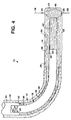
- FIGS. 1-6 Illustrated in FIGS. 1-6 is a method 10 which embodies principles of the present invention.
- the method 10 is representatively illustrated as being performed in a subterranean well 12 having a generally horizontal uncased portion 14 thereof, it is to be understood that the method may be performed in generally vertical, inclined, or otherwise formed portions of wells, without departing from the principles of the present invention.
- directional terms such as "upward”, “downward”, “upper”, “lower”, etc., are used in relation to the methods as depicted in the figures and are not to be construed as limiting the application, utility, manner of operation, etc. of the methods.
- the well 12 includes an upper cased portion 16.
- the generally vertical cased portion 16 extends to the earth's surface.
- the cased portion 16 extends somewhat horizontally at its lower end, facilitating passage of tools, equipment, tubing, etc. from the cased portion 16 into the uncased portion 14.
- curvatures, lengths, etc. of the cased portion 16 and uncased portion 14 are as representatively depicted in FIG. 1 for convenience of illustration, and that these portions may actually extend many thousands of feet into the earth, may be differently proportioned, and may be otherwise dimensioned without departing from the principles of the present invention.
- a work string 18 is operatively positioned within the well 12 by, for example, lowering the work string into the well from the earth's surface.
- the work string 18 may be axially positioned relative to the uncased portion 14 by, for example, lowering the work string from the earth's surface until a lower end 20 of the work string touches a lower end 22 of the well 12 and then picking up on the work string a sufficient amount to position the work string as desired.
- conventional tools such as gamma ray logging tools, etc., may be utilized to axially position the work string 18 within the well 12.
- the work string 18 includes tubing 24, a landing nipple 26, centralizers 28, and a latching profile 30.
- the tubing 24 extends upward to the earth's surface.
- the relative placement and quantities of each of these components may be altered without departing from the principles of the present invention. Indeed, certain of these components, such as the landing nipple 26, may be eliminated from the work string 18, without departing from the principles of the present invention.
- landing nipple 26 is utilized in the method 10 in substantial part to provide a convenient place to operatively dispose a plug within the work string 18 as will be more fully described hereinbelow. It is well known to ordinarily skilled artisans that it is not necessary to provide the landing nipple 26 in order to dispose a plug within the work string 18 and, thus, the nipple may be eliminated from the work string without significantly affecting the performance of the method 10.
- the centralizers 28 operate to radially centralize the work string 18 within the uncased portion 14. For reasons which will become apparent upon consideration of the further detailed description of the method 10 provided hereinbelow, it is desirable for the work string 18 to be radially spaced apart from the uncased portion 14. Although two such centralizers 28 are representatively illustrated in FIG. 1, it is to be understood that any number of centralizers may be utilized in the method 10 without departing from the principles of the present invention.
- the latching profile 30 is shown disposed on the work string 18 proximate the lower end 20 thereof.
- the latching profile 30 is of a conventional type commonly utilized in wellsite operations to locate equipment and tools relative thereto. As representatively illustrated, latching profile 30 is of the type which receives complementarily shaped and radially outwardly extending latches therein. It is to be understood, however, that other latching devices may be utilized in the method 10 without departing from the principles of the present invention. Additionally, as stated hereinabove, it will be readily apparent to an ordinarily skilled artisan that other locating methods may also be utilized in place of a latching device, such as latching profile 30, without departing from the principles of the present invention.
- a viscous fluid 32 is pumped from the earth's surface downward through the tubing 24.
- the fluid 32 is pumped outward through the end 20 of the work string 18 and into an annulus 34 formed radially between the uncased portion 14 and the work string 18. Additionally, the fluid 32 is preferably pumped upwardly into an annulus 36 formed radially between the work string 18 and the cased portion 16 of the well 12.
- the fluid 32 is preferably gelatinous and has properties which substantially prevent its being pumped into a formation 38 surrounding the uncased portion 14 of the well 12. Additionally, it is preferred that the fluid 32 be acid or enzyme soluble for convenience of cleanup after the stimulation operation.
- a suitable preferred fluid 32 is known as K-MAX TM , available from Halliburton Energy Services, Inc. of Duncan, Oklahoma. Another suitable preferred fluid 32 is known as MAX SEAL TM , also available from Halliburton Energy Services, Inc. These preferred fluids 32 are variously described and claimed in U.S. Patent Nos. 5,304,620 and 5,439,057, along with methods of preparing the fluids and controlling fluid loss in high permeability formations. Additionally, wellbore operations utilizing the same or similar preferred fluids are disclosed in our pending European patent application no. 97305538.7 entitled "A METHOD FOR CONTROLLING FLUID LOSS CONTROL IN PERMEABLE FORMATIONS", and a filing date of July 23, 1997.
- the fluid 32 is utilized in substantial part in the method 10 to prevent flow of other fluids into the formation 38 when such flow is not desired, but also to permit such flow when it is desired.
- the method 10 uniquely positions the fluid 32 and work string 18 relative to the formation 38, permits initial stimulation operations therethrough, repositions the work string 18, reconsolidates the fluid 32, permits subsequent stimulation operations therethrough, and permits other operations within the well 12 which enhance the convenience and economics of stimulation operations in the well.
- stimulation operations according to the method 10 are ready to be performed.
- a pressure test is performed before commencement of the stimulation operations by, for example, applying pressure to the annulus 36 at the earth's surface while the tubing 24 is closed off at the earth's surface.
- a balancing pressure may be applied to the tubing 24 at the earth's surface during the pressure test. The pressure test confirms that the tubing 24 and protective casing 40 lining the cased portion 16 do not leak, and that the fluid 32 substantially fills the annulus 34.
- such pressure test will operate to consolidate the fluid, making it relatively impervious to other fluids, and will ensure that the fluid 32 fills substantially all voids which might otherwise be left in the annulus 34.
- the tubing 24 and the annulus 36 above the fluid 32 extending to the earth's surface may be filled with another fluid, such as brine water, mud, etc.
- the centralizers 28 permit the fluid 32 to contact substantially all of the formation 38 exposed to the annulus 34.
- the tubing 24 is, thus, not permitted to rest against the formation 38, which might partially prevent contact between the fluid 32 and the formation. It is to be understood that the tubing 24 may be permitted to contact the formation 38 without departing from the principles of the present invention, but that applicants prefer such contact be avoided.
- the method 10 is shown wherein the work string 18 has been displaced somewhat axially away from the bottom 22 of the well 12.
- a tubing string 42 is received within the tubing 24 such that it extends partially axially outward through the lower end 20 of the tubing.
- the tubing string 42 includes coiled tubing 44 which extends to the earth's surface. It is to be understood, however, that other types of tubing may be utilized in the method 10 without departing from the principles of the present invention.
- the tubing string 42 also includes, in succession from the tubing 44 axially downward, a recloseable ported sub 46, a latching sub 48, and a cutting head 50.
- a recloseable ported sub 46 is included in the tubing string 42 in substantial part to permit flow of stimulation fluids therethrough in a manner which will be more fully described hereinbelow. If, however, it is instead desired to flow stimulation fluids through the work string 18, the ported sub 46 may be eliminated from the tubing string 42.
- the ported sub 46 is conventional and is preferably of the type well known to those skilled in the art which permits opening and reclosure of ports 52 formed thereon. Such opening and reclosure of the ports 52 may be accomplished by various operations, depending upon the type of ported sub utilized. For example, the ports 52 may be opened and closed by utilizing a conventional shifting tool (not shown) conveyed into the ported sub 46 on wireline or slickline, or fluid pressure may be applied to the tubing string 42 and/or work string 18 to open or close the ports.
- a conventional shifting tool (not shown) conveyed into the ported sub 46 on wireline or slickline, or fluid pressure may be applied to the tubing string 42 and/or work string 18 to open or close the ports.
- the latching sub 48 permits positive positioning of the tubing string 42 relative to the work string 18.
- the latching sub 48 has a series of latches 54 projecting radially outwardly therefrom which are capable of operatively engaging the latching profile 30 of the work string 18.
- the cooperative engagement between the latching sub 48 and the latching profile 30 preferably determines an amount of the tubing string 42 which extends axially outward from the work string 18. In this manner, the cutting head 50 may be accurately positioned relative to the end 20 of the work string 18.
- the cutting head 50 is capable of cutting radially outward through the fluid 32 and into the formation 38.
- the cutting head 50 is a hydraulic jet cutting apparatus, but it is to be understood that other cutting apparatus, such as shaped charges, drills, mills, etc., may be utilized in the method 10 without departing from the principles of the present invention.
- a suitable hydraulic jet cutting apparatus which may be utilized for the cutting head 50 is known as the HYDRA-JET TM available from Halliburton Energy Services, Inc. of Duncan, Oklahoma. Applicants prefer that the cutting head 50 is a HYDRA-JET TM head capable of cutting approximately 20-24 inches radially outward into the formation 38.
- HYDRA-JET TM heads form six or eight holes, such as holes 56 shown in FIG.
- the holes 56 facilitate forming of transversely-oriented fractures in the formation 38 relative to the uncased portion 14 of the well 12. Such transversely-oriented fractures are desired in generally horizontal portions of wells which extend substantially within potentially productive formations. It is to be understood that, in accordance with the principles of the present invention, it is not necessary for the holes 56 to be formed in the formation 38. However, applicants prefer that such holes 56 be formed where fracturing of the formation 38 during stimulation operation is desired.
- the ported sub 46 may be extended axially outward from the end 20 of the work string 18 (by disengaging the latching sub 48 from the latching profile 30), and the ports 52 may be opened to permit flow therethrough of stimulation fluid.
- the tubing string 42 may be withdrawn from the work string 18 to permit flow of stimulation fluid through the work string.
- the stimulation fluid is conventional and may include additives, such as proppant, chemicals, etc., which are useful in fracturing the formation 38, maintaining fractures 58 (see FIG. 3) formed thereby open, etc.
- Such stimulation fluids are permitted to enter the holes 56 formed in the formation 38 because the cutting head 50 displaces the fluid 32 between the cutting head and the formation when it is cutting thereinto.
- the fluid 32 is operative to prevent flow of the stimulation fluids into other portions of the formation 38.
- the stimulation fluids are preferably not acidic, due to the fact that the K-MAX TM and MAX SEAL TM fluids are acid soluble. If it is desired to stimulate the formation 38 with acidic stimulation fluids, another viscous fluid should be used for the fluid 32.
- FIG. 3 shows the tubing string 42 removed from within the work string 18, as will be the case if the stimulation fluids are flowed through the work string, instead of through the ported sub 46 on the tubing string.
- a relatively small quantity of the fluid 32 mixed with sand or other proppant may be spotted opposite the openings 56.
- the mixed fluid 32 and sand forms a viscous plug 60 which is capable of preventing subsequent flow of fluids into the openings 56 and fractures 58, and generally into the formation 38 adjacent the openings 56.
- the plug 60 may also extend into the openings 56.
- the plug 60 may be delivered to the uncased portion 14 by the same means used to convey the stimulation fluids, e.g., the tubing string 42 or the work string 18.
- the plug 60 be "tailed-in" with the stimulation fluids, so that the plug is delivered to the well 12 immediately following the stimulation fluids. In this manner, a pressure increase may be detected at the earth's surface when the plug 60 is in place and preventing further fluid flow into the formation 38.
- the plug 60 it is not necessary for the plug 60 to be utilized in the method 10. As will be more fully described hereinbelow, the fluid 32 in the annulus 34 may be reconsolidated to fill any voids therein, without the need for depositing a separate plug 60 therein. Applicants prefer utilization of the plug 60, however, because it is relatively easy to place the plug immediately after the stimulation step and the sand, or other proppant, mixed therein provides an enhanced strength matrix in this area of the uncased portion 14 which has been significantly disturbed by flow of jet cutting and stimulation fluids therethrough.
- the work string 18 has been displaced axially upward within the well 12, thereby displacing the end 20 axially away from the plug 60.
- the work string 18 is so displaced in order to position the work string relative to the uncased portion 14 for performing another stimulation operation (see FIG. 5, wherein the cutting head 50 is positioned relative to the end 20 of the work string 18 for performing another stimulation operation).
- a void (indicated in FIG. 4 by solid outline 62) is created in the fluid 32 between the plug 60 and the end 20 of the work string 18 when the work string is so displaced.
- the void 62 is filled by applying pressure to the annulus 36 at the earth's surface to flow the fluid 32 downward in the annulus 36 and into the uncased portion 14.
- the fluid 32 was initially stored in the annulus 36.
- the fluid 32 should initially extend sufficiently upwardly into the annulus 36 to fill all such voids 62 to be created during stimulation of the well 12.
- a sufficient pressure may also be applied to the work string 18 to prevent the fluid 32 from flowing upwardly into the work string.
- a retrievable plug 64 may be operatively installed in the landing nipple 26. By installing the plug 64 in the landing nipple 26, pressure may be maintained on the annulus 36 for an extended period of time.
- K-MAX TM or MAX SEAL TM is utilized for the fluid 32
- such application of pressure thereto will not only cause the fluid to fill the void 62, but will also cause the fluid to reconsolidate so that no interfaces are present between the fluid initially delivered to the annulus 34 and the fluid which subsequently fills the void 62.
- This lack of interfaces in the reconsolidated fluid 32 (which prevents flow of other fluids through such interfaces) is a reason that applicants prefer use of the K-MAX TM or MAX SEAL TM for the fluid 32.
- the pressure is applied to the annulus 36 for an extended period of time, for example, approximately eight hours, to ensure that the void 62 is filled, the fluid 32 is reconsolidated (if the preferred fluid is utilized), and that no leaks are present.
- the pressure is removed from the annulus 36 and the plug 64 is retrieved from the work string 18. At this point, another stimulation operation may be performed.
- the void 62 may be filled with the fluid 32 prior to any subsequent stimulation operations in the uncased portion 14, since the plug 60 isolates the openings 56 from any other fluids which may be flowed through the work string 18 or tubing string 42 thereafter. Applicants, however, prefer that the void 62 be filled with the fluid 32 to ensure that extraneous fluid paths are not left in the uncased portion 14 between stimulation operations. Note, also, that the void 62 may be filled alternatively by flowing a relatively small quantity of the fluid 32 through the work string 18 after the plug 60 has been delivered to the uncased portion 14 and after the work string has been displaced.
- centralizers 28 are shown having entered the casing 40 when the work string 18 was displaced relative to the uncased portion 14. It is to be understood that the centralizers 28 may be otherwise spaced apart so that none of the centralizers 28 enters the casing 40 when the work string 18 is displaced without departing from the principles of the present invention.
- the tubing string 42 is shown again received within the work string 18.
- the latching sub 48 is latched into the latching profile 30 and the cutting head 50 extends axially outward from the end 20 of the work string 18.
- the cutting head 50 has formed holes 66 into the formation 38, similar to the previously-formed holes 56.
- any desired number of axially spaced apart stimulation operations may be located within the uncased portion 14 according to the principles of the method 10.
- a first set of holes such as holes 56
- stimulation fluids may be flowed into the formation 38
- the work string 18 may be displaced relative to the uncased portion 14
- a second set of holes such as holes 66
- stimulation fluids may be flowed into the formation
- the work string may be displaced relative to the uncased portion
- a third set of holes may be formed, etc., until a desired number of stimulation locations are achieved.
- voids such as void 62 and other similar voids formed by displacement of the work string.
- stimulation fluids are flowed through the work string 18 or the ported sub 46 of the tubing string 42 and into the openings 66. It is undesirable for these stimulation fluids to also flow into the previously-formed openings 56.
- the plug 60 and the fluid 32 filling the void 62 prevent such undesirable flow of the stimulation fluids.
- fractures 68 may be formed extending transversely outward from the uncased portion 14.
- the stimulation fluids may be flowed through the work string 18 with the tubing string 42 withdrawn therefrom, the stimulation fluids may be flowed through the ports 52 of the ported sub 46, or may be otherwise flowed into the openings 66 without departing from the principles of the present invention.
- the well 12 is shown with a production tubing string 70 disposed therein.
- the production tubing string 70 may be inserted into the well 12 after the work string 18 is removed therefrom, or the work string 18 may be used as the production tubing string 70 without departing from the principles of the present invention.
- a coiled tubing string 72 is shown received within the production tubing string 70.
- the coiled tubing string 72 may be inserted into the production tubing string 70 after the tubing string 42 is removed from the well 12, or the tubing string 42 may be utilized as the coiled tubing string 72 without departing from the principles of the present invention.
- the production tubing string 70 includes a production packer 74 which operates to isolate the annulus 36 from the uncased portion 38. In this manner, production fluids may be retrieved from the formation 38 via the production tubing 70 extending to the earth's surface, according to conventional practice. It is to be understood that, during normal subsequent production of fluids from the uncased portion 14, the coiled tubing 72 is preferably not disposed within the production tubing 70.
- the coiled tubing 72 is shown extending into the uncased portion 14 near the end 22 thereof.
- a cleanup fluid, indicated by arrows 76 is flowed through the coiled tubing 72 from the earth's surface to remove the viscous fluid 32 from the uncased portion 14 prior to placing the well 12 into production.
- a mild acidic solution may be used for the cleanup fluid 76.
- such a mild acidic solution is approximately 3% acid. In this manner, the fluid 32 is removed from contact with the formation 38 and is flushed upwardly through the production tubing string 70.
- the method 10 which permits multiple stimulation locations within the uncased portion 14 of the well 12.
- the method 10 permits such multiple stimulation locations without requiring the use of expensive and unreliable inflatable packers, and without requiring the uncased portion 14 to be cased and cemented.
- FIG. 7 another method 80 embodying principles of the present invention is representatively illustrated.
- the method 80 differs from the method 10 in that a work string 82 is utilized in place of the separate work string 18 and tubing string 42.
- the work string 82 includes the landing nipple 26a, tubing 24a, and centralizer 28a. Additionally, the work string 82 includes a ported sub 84 and a cutting head 86.
- the cutting head 86 is similar to the cutting head 50, and the ported sub 84 is similar to the ported sub 46 utilized in the method 10. However, the cutting head 86 and ported sub 84 are configured for attachment to the work string 82 which would in most cases be larger in diameter than the coiled tubing 44.
- the cutting head 86 may be conveniently positioned relative to the uncased portion 14a of the well 12a at a desired stimulation location. Holes, such as holes 56, may then be cut into the formation 38a by the cutting head. Ports 88 on the ported sub 84 may then be opened to permit flow therethrough of stimulation fluids and a plug, such as plug 60, may be delivered through the ports.
- the work string 82 may then be displaced axially relative to the formation to another stimulation location.
- the ports may be closed, and a plug, such as retrievable plug 64 may be operatively installed in the landing nipple 26a.
- the fluid 32 may be reconsolidated and any voids, such as void 62, filled by applying pressure to the annulus 36a (and the work string 82, if the retrievable plug is not installed in the landing nipple 26a).
- the stimulation operation may be repeated a desired number of times, as with method 10, to produce a desired number of axially spaced apart stimulation locations in the uncased portion 14a.
- the work string 82 may then be withdrawn from the well 12a and replaced with a production tubing string, such as production tubing string 70 shown in FIG. 6.
- the work string 82 may be utilized as a production tubing string and cleanup fluid, such as fluid 76, may be circulated through the ports 88 to remove the viscous fluid 32a.
- a benefit of the method 80 is that the larger diameter cutting head 86 may permit cutting of deeper holes into the formation 38a, since the cutting head is radially closer to the formation.
- An additional benefit is that the ports 88 may have larger flow area than the ports 52 of the ported sub 46.
- Yet another benefit of the method 80 is that there is no need to insert and remove the tubing string 42 into and from the work string 82.
- Still another benefit of the method 80 is that only one assembly, the work string 82, must be positioned relative to the uncased portion 14a.
- FIG. 8 a method 90 embodying principles of the present invention is representatively illustrated. Elements of the method 90 which are similar to elements previously described hereinabove are indicated using the same numbers, with an added suffix "b".
- the method 90 differs from the method 10 in that a packer 92 having an axially extending seal bore 94 formed therethrough is set in the casing 40b, and a work string 96 having an axially spaced apart series of seals 98 is positioned in the well 12b, such that the seals pass axially through and successively sealingly engage the seal bore 94.
- the seal bore 94 may be otherwise connected to the packer, for example, by attaching a tubular member (not shown) having the seal bore formed therethrough to the packer.
- the work string 96 includes the latching profile 30b proximate the end 20b thereof.
- the latching profile 30b operatively engages latches 100 extending radially outward from a latching sub 102 attached axially between a cutting head 104 and coiled tubing 106 extending to the earth's surface.
- the cutting head 104, latching sub 102, and coiled tubing 106 are included in a tubing string 108 received within the work string 96.
- tubing string 108 does not include a ported sub, such as ported sub 46 of the tubing string 42.
- stimulation fluids are conveyed to the uncased portion 14b of the well 12b via the work string 96 and, thus, a ported sub is not needed on the tubing string 108.
- a ported sub could be included in the tubing string 108, and stimulation fluids could be conveyed to the uncased portion 14b via the ported sub, without departing from the principles of the present invention.
- the packer 92 is set in the casing 40b and the work string 96 is inserted therein.
- the fluid 32b is spotted in the uncased portion 14b and upwardly into the annulus 36b by, for example, flowing the fluid through the work string 96 from the earth's surface.
- none of the seals 98 sealingly engage the seal bore 94.
- the work string 96 is axially displaced relative to the uncased portion 14b to position the cutting head 104 opposite a desired stimulation location and to position one of the sets of seals 98 in sealing engagement with the seal bore 94.
- such positioning of the cutting head 104 opposite the desired stimulation location will comprise positioning the end 20b of the work string relative to the desired stimulation location, so that when the latching sub is subsequently operatively engaged with the latching profile 30b, the cutting head 104 will be properly positioned.
- holes such as holes 56
- the tubing string 108 is then withdrawn from the work string 96 and stimulation fluids are flowed through the work string and into the formation 38b via the holes.
- the sealing engagement of the seals 98 with the seal bore 94 prevents displacement of the fluid 32b further upward into the annulus 36b due to the pressure applied to the stimulation fluids to flow the fluids into the formation 38b.
- a plug such as plug 60
- the plug may be "tailed-in" following the stimulation fluids, or may be separately conveyed through the work string.
- any voids left by the stimulation operation may be filled by any of the procedures described hereinabove, such as by applying pressure to the annulus 36b to flow a portion of the fluid 32b into the voids (after the seals 98 no longer sealingly engage the seal bore 94).
- the work string 96 is then displaced axially relative to the uncased portion 14b so that the seals 98 no longer sealingly engage the seal bore 94. Pressure may then be applied to the annulus 36b from the earth's surface to flow the fluid 32b from the annulus 36b to any voids left by such displacement of the work string 96. A balancing pressure may also be applied to the work string 96 at the earth's surface to prevent flow of the fluid 32b into the work string.
- Another of the sets of seals 98 may then be sealingly engaged with the seal bore 94.
- the sets of seals 98 are axially spaced apart so that as each is successively sealingly engaged with the seal bore 94 prior to corresponding successive stimulation operations, the cutting head 104 is positioned opposite successive desired stimulation locations in the uncased portion 14b.
- the number of sets of seals 98 and the axial spacing therebetween corresponds to a desired number and axial spacing of stimulation locations.
- the work string 96 and the tubing string 108 are withdrawn from the well 12b and a production tubing string, such as production tubing string 70 shown in FIG. 6, is installed in the well.
- the well 12b is cleaned by, for example, inserting a coiled tubing, such as coiled tubing 72, into the production tubing string and flowing a cleanup fluid, such as mild acid or an enzyme solution, therethrough as described hereinabove for the method 10.
- the work string 96 may be utilized as the production tubing string and/or the tubing string 108 may be utilized as the coiled tubing for use in cleaning the fluid 32b from the well 12b.
- Benefits derived from use of the method 90 include the fluid pressure and flow control afforded by the sealing engagement of the seals 98 with the seal bore 94. Especially during the stimulation operations, such sealing engagement is beneficial in preventing flow of the fluid 32b within the annulus 36b. Another benefit is that it is not necessary to maintain pressure on the annulus 36b during the stimulation operations to balance the pressure of the stimulation fluids flowed through the work string 96.
- FIG. 9 a method 110 embodying principles of the present invention is representatively illustrated. Elements of the method 110 which are similar to previously described elements are indicated using the same reference numbers, with an added suffix "c".
- the method 110 differs from the method 10 in substantial part in that a work string 112 is not axially displaced relative to the uncased portion 14c between successive stimulation operations.
- the work string 112 includes an axially spaced apart series of sliding sleeves 114 which are positioned in the work string opposite corresponding desired stimulation locations in the uncased portion 14c.
- the sliding sleeves 114 are conventional and are preferably of the type which may be alternately opened and closed to alternately permit or prevent radial flow therethrough. Such opening and closing of each of the sliding sleeves 114 may be accomplished by, for example, a shifting tool conveyed on a slickline, or by applying fluid pressure to the annulus 36c and/or the work string 112 at the earth's surface, as with the ported sub 46.
- the fluid 32c is disposed within the uncased portion 14c by, for example, positioning the work string 112 in the uncased portion, opening one of the sliding sleeves 114, and flowing the fluid 32c therethrough, or, as another example, by spotting the fluid 32c in the uncased portion utilizing coiled tubing before the work string 112 is positioned therein.
- the work string 112 is positioned in the uncased portion 14c so that each of the sliding sleeves 114 is radially opposite a desired stimulation location.
- a tubing string 116 is received in the work string 112.
- the tubing string 116 includes a coiled tubing 118 and a cutting head 50c.
- the corresponding sliding sleeve 114 is opened and the cutting head 50c is operated to cut through the open sliding sleeve and into the formation.
- An alignment device (not shown) may be provided if desired to align the cutting head 50c with radially extending openings formed through the sliding sleeve 114.
- a latching profile and latching sub such as latching profile 30 and latching sub 48, may be provided to ensure positive axial alignment of the cutting head 50c with the sliding sleeve 114 at each desired stimulation location.
- the tubing string 116 is withdrawn from the work string 112.
- Stimulation fluids are flowed from the earth's surface, through the work string, and outward through the open sliding sleeve 114.
- the stimulation fluids then enter the formation 38c via the holes cut by the cutting head 50c.
- the open sliding sleeve 114 is closed and another one of the sliding sleeves 114 is opened.
- the tubing string 116 is again inserted into the work string 112 so that the cutting head 50c is aligned with the open sliding sleeve 114.
- the hole cutting and stimulating operations may then be repeated as needed to produce a desired number of stimulation locations in the uncased portion 14c.
- the tubing string 116 and work string 112 may then be withdrawn from the well 12c and a production tubing string, such as production tubing string 70 shown in FIG. 6, may be installed therein, or the work string 112 may be utilized as a production tubing string. If the work string 112 is utilized as a production tubing string, one or more of the sliding sleeves 114 may remain open for production of fluid from the formation 38c therethrough.
- the fluid 32c may be cleaned from the well 12c using any of the previously described procedures, such as by circulating a mild acid solution through the uncased portion 14c.
- foamed fluid may be used in the cleanup procedure to achieve a lower effective density during circulation.
- FIG. 10 a method 120 embodying principles of the present invention is representatively illustrated. Elements of the method 120 which are similar to previously described elements are indicated using the same reference numbers, with an added suffix "d".
- the method 120 differs from the method 90 in substantial part in that a work string 122 is axially displaced relative to the uncased portion 14d between successive stimulation operations and is sealingly engaged by a set of seals 124 attached to a packer 126 set in the casing 40d.
- the seals 124 may be of the type known to those skilled in the art as “stripper rubbers", “cup seals”, or may be another type of seal capable of sealingly engaging the work string 122. Additionally, the seals 124 are preferably capable of sealingly engaging the work string 122 during axial displacement of the work string relative to the uncased portion 14d.
- the seals 124 are attached to the packer 126 via a generally tubular mechanism 128.
- the mechanism 128 is preferably of the type known to those of ordinary skill in the art that is capable of releasing the seals 124 for retrieval of the seals to the earth's surface. Such release of the seals 124 may be accomplished by, for example, shifting a sleeve (not shown) within the mechanism 128, applying a predetermined pressure to the mechanism, etc.
- the mechanism 128 is also preferably of the type known to those of ordinary skill in the art that includes a recloseable bypass port 130.
- the bypass port 130 permits fluid communication between the annulus 36d and the annulus 34d when it is open. When closed, the bypass port 130 isolates the annulus 36d from the annulus 34d. Opening and closing of the bypass port 130 may be accomplished by, for example, shifting a sleeve (not shown) within the mechanism 128, applying a predetermined pressure to the mechanism, etc.
- the packer 126 is set in the casing 40d and the work string 122 is inserted therein.
- the work string 122 is axially displaced relative to the uncased portion 14d to position the cutting head 104d opposite a desired stimulation location.
- positioning of the cutting head 104d opposite the desired stimulation location will comprise positioning the end 20d of the work string relative to the desired stimulation location, so that when the latching sub is subsequently operatively engaged with the latching profile 30d, the cutting head 104d will be properly positioned.
- the fluid 32d is spotted in the uncased portion 14d and upwardly into the annulus 36d by, for example, flowing the fluid through the work string 122 from the earth's surface.
- the bypass port 130 is open. After the fluid 32d has substantially filled the uncased portion 14d, it is preferably also flowed through the bypass port 130 and upward sufficiently far into the annulus 36d. The bypass port 130 is then closed.
- holes such as holes 56
- the tubing string 108d is then withdrawn from the work string 122 and stimulation fluids are flowed through the work string and into the formation 38d via the holes.
- the sealing engagement of the seals 124 with the work string 122 prevents displacement of the fluid 32d further upward into the annulus 36d due to the pressure applied to the stimulation fluids to flow the fluids into the formation 38d.
- a plug such as plug 60
- the plug may be "tailed-in" following the stimulation fluids, or may be separately conveyed through the work string.
- any voids left by the stimulation operation may be filled by any of the procedures described hereinabove, such as by opening the bypass port 130 and applying pressure to the annulus 36d to flow a portion of the fluid 32d into the voids.
- the work string 122 is then displaced axially relative to the uncased portion 14d after opening the bypass port 130. Pressure may then be applied to the annulus 36d from the earth's surface to flow the fluid 32d from the annulus 36d, through the bypass port 130, to any voids left by such displacement of the work string 122. A balancing pressure may also be applied to the work string 122 at the earth's surface to prevent flow of the fluid 32d into the work string.
- bypass port 130 is closed and the above procedure is repeated, the cutting head 104d being positioned opposite another desired stimulation location to form holes in the formation 38d and form openings through the fluid 34d.
- the work string 122 and the tubing string 108d are withdrawn from the well 12d and a production tubing string, such as production tubing string 70 shown in FIG. 6, is installed in the well.
- the well 12d is cleaned by, for example, inserting a coiled tubing, such as coiled tubing 72, into the production tubing string and flowing a cleanup fluid, such as mild acid or an enzyme solution, therethrough as described hereinabove for the method 10.
- the work string 122 may be utilized as the production tubing string and/or the tubing string 108d may be utilized as the coiled tubing for use in cleaning the fluid 32d from the well 12d.
- FIG. 11 a method 140 embodying principles of the present invention is representatively illustrated. Elements of the method 140 which are similar to previously described elements are indicated using the same reference numbers, with an added suffix "e".
- the method 140 differs from the method 90 in substantial part in that a work string 142 is axially displaced relative to the uncased portion 14e between successive stimulation operations and a packer 144 attached to the work string is set in the casing 40e during stimulation operations and is unset during axial displacement of the work string.
- the packer 144 is preferably of the type well known to those of ordinary skill in the art that is capable of being set and unset repeatedly within the subterranean well 12e.
- the packer 144 isolates the annulus 36e from the annulus 34e and substantially fixes the axial position of the work string 142 relative to the casing 40e.
- the packer 144 is unset, fluid communication is permitted between the annulus 36e and the annulus 34e, and the work string 142 may be axially displaced relative to the casing 40e.
- the packer 144 may be set and unset by, for example, manipulation of the work string 142 at the earth's surface.
- the packer 144 is conveyed into the well 12e attached to the work string 142.
- the work string 142 is axially displaced relative to the uncased portion 14e to position the cutting head 104e opposite a desired stimulation location.
- positioning of the cutting head 104e opposite the desired stimulation location will comprise positioning the end 20e of the work string relative to the desired stimulation location, so that when the latching sub is subsequently operatively engaged with the latching profile 30e, the cutting head 104e will be properly positioned.
- the fluid 32e is spotted in the uncased portion 14e and upwardly into the annulus 36e by, for example, flowing the fluid through the work string 142 from the earth's surface. During such spotting of the fluid 32e, preferably the packer 144 remains unset. After the fluid 32e has substantially filled the uncased portion 14e and extends upward sufficiently far into the annulus 36e, the packer 144 is set in the casing 40e.
- holes such as holes 56
- the tubing string 108e is then withdrawn from the work string 142 and stimulation fluids are flowed through the work string and into the formation 38e via the holes.
- the sealing engagement of the packer 144 with the casing 40e prevents displacement of the fluid 32e further upward into the annulus 36e due to the pressure applied to the stimulation fluids to flow the fluids into the formation 38e.
- a plug such as plug 60
- the plug may be "tailed-in" following the stimulation fluids, or may be separately conveyed through the work string.
- any voids left by the stimulation operation may be filled by any of the procedures described hereinabove, such as by unsetting the packer 144 and applying pressure to the annulus 36e to flow a portion of the fluid 32e into the voids.
- the work string 142 is then displaced axially relative to the uncased portion 14e to a position corresponding to another desired stimulation location after the packer 144 is unset. Pressure may then be applied to the annulus 36e from the earth's surface to flow the fluid 32e from the annulus 36e to any voids left by such displacement of the work string 142. A balancing pressure may also be applied to the work string 142 at the earth's surface to prevent flow of the fluid 32e into the work string.
- the packer 144 may again be set in the casing 40e, the tubing string 108e may be inserted into the work string 142 and withdrawn therefrom, and stimulation fluids may be flowed into the formation 38e at the next desired stimulation location.
- the work string 142 and the tubing string 108e are withdrawn from the well 12e and a production tubing string, such as production tubing string 70 shown in FIG. 6, is installed in the well.
- the well 12e is cleaned by, for example, inserting a coiled tubing, such as coiled tubing 72, into the production tubing string and flowing a cleanup fluid, such as mild acid or an enzyme solution, therethrough as described hereinabove for the method 10.
- the work string 142 may be utilized as the production tubing string and/or the tubing string 108e may be utilized as the coiled tubing for use in cleaning the fluid 32e from the well 12e.
- each of the procedures described in each of the above methods 10, 80, 90, 110, 120 and 140 may be performed by utilizing a succession of varied tools and equipment without departing from the principles of the present invention.
- a tubing string such as tubing string 42
- the tubing string may be changed somewhat between each successive insertion or withdrawal by adding, eliminating, or substituting various components thereof.
- Such changes to work strings, tubing strings, etc. are contemplated by the applicants and are encompassed by the principles of the present invention.
Abstract
Description
Claims (10)
- A method of stimulating a portion of a subterranean well (12) at axially spaced apart desired stimulation locations therein, the well portion intersecting a formation (38), comprising : disposing a viscous fluid (32) within the well portion; forming an opening (56) through the viscous fluid (32) at a first one of the desired stimulation locations; and flowing stimulation fluids through the opening and into the formation (38) at the first desired stimulation location, whereby the viscous fluid (32) substantially prevents flow of the stimulation fluids into any portion of the formation (38) other than at the first desired stimulation location.
- A method according to claim 1, wherein the opening (58) is extended into the formation (38).
- A method of injecting a fluid into successive desired locations in a formation (38) surrounding a subterranean wellbore (12) while preventing the injection of the fluid into other locations in the formation (38) exposed to the wellbore, the method comprising the steps of: contacting the formation (38) exposed to the wellbore (12) with a flowable material (32), the material (32) being capable of flowing within the wellbore (12) and substantially incapable of flowing into the formation (38); providing a tubular member (24); disposing an end of the tubular member (24) in the flowable material (32); forming a first flow passage (56) from the tubular member (24) through the flowable material (32) to a first one of the desired locations in the formation (38); and flowing the fluid through the tubular member (24) and the first flow passage (56) to the first one of the desired locations.
- A method according to claim 3, further comprising the steps of: closing the first flow passage (56); forming a second flow passage (66) from the tubular member (24) through the flowable material (32) to a second one of the desired locations in the formation (38); and flowing the fluid through the tubular member (24) and the second flow passage (66) to the second one of the desired locations.
- A method of stimulating a formation (38) intersecting a subterranean well (12), comprising: disposing a work string (18) within the subterranean well (12); disposing a viscous fluid (32) in the subterranean well (12) about an end of the work string, the viscous fluid (32) contacting the formation (38); disposing the tubing string (42) within the work string (18), the tubing string (42) having a cutting head (50) attached to an end thereof; positioning the tubing string end relative to the work string end, such that the cutting head (50) extends axially outward from the work string end; forming an opening (56) from the cutting head (50) to the formation (38) through the viscous fluid (32); and flowing stimulation fluid through the opening (56) to the formation (38).
- A method according to claim 5, wherein the stimulation fluid is flowed through the opening (56) by flowing the stimulation fluid through the work string (18).
- A method of stimulating a formation (38a) intersecting a subterranean well (12a), comprising: disposing a work string (82) within the subterranean well (12a), the work string (82) having a cutting head (86) attached to an end thereof; disposing a viscous fluid (32a) in the subterranean well (12a) about the work string end, the viscous fluid (32a) contacting the formation (38a); forming a first opening (56) from the cutting head (86) to the formation (38a) through the viscous fluid (32a); and flowing stimulation fluid through the first opening (56) to the formation (38a).
- A method of stimulating a formation (38b) intersecting a subterranean well (12b), comprising: setting a packer (92) in the well (12b), the packer (92) having a seal bore (94); disposing a work string (96) within the subterranean well (12b), the work string (96) having an axially spaced apart series of seals (98) externally disposed on an outer side surface of the work string (96), and being reciprocably received in the seal bore (94); disposing a viscous fluid (32b) in the subterranean well (12b) about an end of the work string (96), the viscous fluid (32b) contacting the formation (38b); disposing a tubing string (108) within the work string (96), the tubing string (108) having a cutting head (104) attached to an end thereof; positioning the tubing string end relative to the work string end, such that the cutting head (104) extends axially outward from the work string end; sealingly engaging one of the seals (98) with the seal bore (94); forming a first opening (56) from the cutting head (104) to the formation (38b) through the viscous fluid (32b); and flowing stimulation fluid through the first opening (56) to the formation (38b).
- A method of stimulating a formation (38c) intersecting a subterranean well (12c), comprising: disposing a work string (112) within the subterranean well (12c), the workstring (112) having an axially spaced apart series of sliding sleeves (114) connected to the remainder of the work string (112); positioning the work string (112) within the subterranean well (12c) such that each of the sliding sleeves (114) is radially opposite a desired stimulation location in the formation (38c); disposing a viscous fluid (32c) in the subterranean well (12c) about an end of work string (112), the viscous fluid (32c) contacting the formation (38c); opening a first one of the sliding sleeves (114); disposing the tubing string (116) within the work string (112) the tubing string (116) having a cutting head (50c) attached to an end thereof; positioning the tubing string end relative to the work string end, such that the cutting head (50c) is aligned with the first one of the sliding sleeves (114); forming a first opening (56) from the cutting head (50c) to the formation (38c) through the first one of the sliding sleeves (114) and the viscous fluid (32c); and flowing stimulation fluid through the first opening (56) to the formation (38c).
- A method of stimulating a formation (38e) intersecting a subterranean well (12e), comprising: disposing a tubular string (142) within the subterranean well, thereby forming an annulus (34e,36e) between the tubular string (142) and the well (12e); disposing a viscous fluid (32e) in the subterranean well (12e) about an end of the tubular string (142) in a first portion (34e) of the annulus (34e,36e), the viscous fluid (32e) contacting the formation (38e); sealingly engaging the tubular string (142) with the subterranean well (12e), thereby isolating the first annulus portion (34e) from a second annulus portion (36e); forming a first opening (56) to the formation (38e) through the viscous fluid (32e); and flowing stimulation fluid through the first opening (56) to the formation (38e).
Applications Claiming Priority (2)
| Application Number | Priority Date | Filing Date | Title |
|---|---|---|---|
| US68954796A | 1996-08-09 | 1996-08-09 | |
| US689547 | 1996-08-09 |
Publications (2)
| Publication Number | Publication Date |
|---|---|
| EP0823538A2 true EP0823538A2 (en) | 1998-02-11 |
| EP0823538A3 EP0823538A3 (en) | 1999-01-27 |
Family
ID=24768947
Family Applications (1)
| Application Number | Title | Priority Date | Filing Date |
|---|---|---|---|
| EP97306061A Withdrawn EP0823538A3 (en) | 1996-08-09 | 1997-08-08 | Method of stimulating a subterranean well |
Country Status (2)
| Country | Link |
|---|---|
| EP (1) | EP0823538A3 (en) |
| NO (1) | NO973644L (en) |
Cited By (5)
| Publication number | Priority date | Publication date | Assignee | Title |
|---|---|---|---|---|
| EP0916805A3 (en) * | 1997-11-12 | 2001-02-28 | Halliburton Energy Services, Inc. | Apparatus and method for stimulating a subterranean well |
| WO2005090747A1 (en) * | 2004-03-24 | 2005-09-29 | Halliburton Energy Services, Inc. | Methods of isolating hydrajet stimulated zones |
| US9303501B2 (en) | 2001-11-19 | 2016-04-05 | Packers Plus Energy Services Inc. | Method and apparatus for wellbore fluid treatment |
| US10030474B2 (en) | 2008-04-29 | 2018-07-24 | Packers Plus Energy Services Inc. | Downhole sub with hydraulically actuable sleeve valve |
| US10053957B2 (en) | 2002-08-21 | 2018-08-21 | Packers Plus Energy Services Inc. | Method and apparatus for wellbore fluid treatment |
Citations (6)
| Publication number | Priority date | Publication date | Assignee | Title |
|---|---|---|---|---|
| US2223397A (en) * | 1938-04-18 | 1940-12-03 | Dow Chemical Co | Treatment of wells |
| US2259429A (en) * | 1939-08-01 | 1941-10-14 | Dow Chemical Co | Method of treating wells |
| US3191697A (en) * | 1953-11-30 | 1965-06-29 | Mcgaffey Taylor Corp | Subsurface earth formation treating tool |
| US4842068A (en) * | 1986-12-31 | 1989-06-27 | Dowell Schlumberger Incorporated | Process for selectively treating a subterranean formation using coiled tubing without affecting or being affected by the two adjacent zones |
| US5316082A (en) * | 1992-08-28 | 1994-05-31 | Mobil Oil Corporation | Method of effectively diverting treating fluid from a high permeability interval during well stimulation |
| US5353874A (en) * | 1993-02-22 | 1994-10-11 | Manulik Matthew C | Horizontal wellbore stimulation technique |
-
1997
- 1997-08-07 NO NO973644A patent/NO973644L/en unknown
- 1997-08-08 EP EP97306061A patent/EP0823538A3/en not_active Withdrawn
Patent Citations (6)
| Publication number | Priority date | Publication date | Assignee | Title |
|---|---|---|---|---|
| US2223397A (en) * | 1938-04-18 | 1940-12-03 | Dow Chemical Co | Treatment of wells |
| US2259429A (en) * | 1939-08-01 | 1941-10-14 | Dow Chemical Co | Method of treating wells |
| US3191697A (en) * | 1953-11-30 | 1965-06-29 | Mcgaffey Taylor Corp | Subsurface earth formation treating tool |
| US4842068A (en) * | 1986-12-31 | 1989-06-27 | Dowell Schlumberger Incorporated | Process for selectively treating a subterranean formation using coiled tubing without affecting or being affected by the two adjacent zones |
| US5316082A (en) * | 1992-08-28 | 1994-05-31 | Mobil Oil Corporation | Method of effectively diverting treating fluid from a high permeability interval during well stimulation |
| US5353874A (en) * | 1993-02-22 | 1994-10-11 | Manulik Matthew C | Horizontal wellbore stimulation technique |
Cited By (14)
| Publication number | Priority date | Publication date | Assignee | Title |
|---|---|---|---|---|
| EP0916805A3 (en) * | 1997-11-12 | 2001-02-28 | Halliburton Energy Services, Inc. | Apparatus and method for stimulating a subterranean well |
| US9366123B2 (en) | 2001-11-19 | 2016-06-14 | Packers Plus Energy Services Inc. | Method and apparatus for wellbore fluid treatment |
| US10822936B2 (en) | 2001-11-19 | 2020-11-03 | Packers Plus Energy Services Inc. | Method and apparatus for wellbore fluid treatment |
| US10087734B2 (en) | 2001-11-19 | 2018-10-02 | Packers Plus Energy Services Inc. | Method and apparatus for wellbore fluid treatment |
| US9963962B2 (en) | 2001-11-19 | 2018-05-08 | Packers Plus Energy Services Inc. | Method and apparatus for wellbore fluid treatment |
| US9303501B2 (en) | 2001-11-19 | 2016-04-05 | Packers Plus Energy Services Inc. | Method and apparatus for wellbore fluid treatment |
| US10053957B2 (en) | 2002-08-21 | 2018-08-21 | Packers Plus Energy Services Inc. | Method and apparatus for wellbore fluid treatment |
| US10487624B2 (en) | 2002-08-21 | 2019-11-26 | Packers Plus Energy Services Inc. | Method and apparatus for wellbore fluid treatment |
| US7766083B2 (en) | 2004-03-24 | 2010-08-03 | Halliburton Energy Services, Inc. | Methods of isolating hydrajet stimulated zones |
| US7681635B2 (en) | 2004-03-24 | 2010-03-23 | Halliburton Energy Services, Inc. | Methods of fracturing sensitive formations |
| US7225869B2 (en) | 2004-03-24 | 2007-06-05 | Halliburton Energy Services, Inc. | Methods of isolating hydrajet stimulated zones |
| WO2005090747A1 (en) * | 2004-03-24 | 2005-09-29 | Halliburton Energy Services, Inc. | Methods of isolating hydrajet stimulated zones |
| US10030474B2 (en) | 2008-04-29 | 2018-07-24 | Packers Plus Energy Services Inc. | Downhole sub with hydraulically actuable sleeve valve |
| US10704362B2 (en) | 2008-04-29 | 2020-07-07 | Packers Plus Energy Services Inc. | Downhole sub with hydraulically actuable sleeve valve |
Also Published As
| Publication number | Publication date |
|---|---|
| NO973644D0 (en) | 1997-08-07 |
| NO973644L (en) | 1998-02-10 |
| EP0823538A3 (en) | 1999-01-27 |
Similar Documents
| Publication | Publication Date | Title |
|---|---|---|
| US6047773A (en) | Apparatus and methods for stimulating a subterranean well | |
| US5058676A (en) | Method for setting well casing using a resin coated particulate | |
| EP0852652B1 (en) | Method for isolating multi-lateral well completions while maintaining selective drainhole re-entry access | |
| US6070666A (en) | Fracturing method for horizontal wells | |
| RU2395667C1 (en) | Method of borehole conditioning with collection of productive intervals | |
| CA1246438A (en) | Hydraulic fracturing and gravel packing method employing special sand control technique | |
| US20070284106A1 (en) | Method and apparatus for well drilling and completion | |
| US4917188A (en) | Method for setting well casing using a resin coated particulate | |
| EP1312750A2 (en) | Method and apparatus for selective horizontal well re-entry using retrievable diverter oriented by logging means | |
| US5197543A (en) | Horizontal well treatment method | |
| EP0287735A2 (en) | Method for completing a drainhole well | |
| CA2970650C (en) | Establishing control of oil and gas producing well bore through application of self-degrading particulates | |
| US6408942B2 (en) | One-trip squeeze pack system and method of use | |
| US4195690A (en) | Method for placing ball sealers onto casing perforations | |
| EP2659090B1 (en) | Methods for drilling and stimulating subterranean formations for recovering hydrocarbon and natural gas resources | |
| EP0823538A2 (en) | Method of stimulating a subterranean well | |
| US4759408A (en) | Method of shutting off a portion of a producing zone in a hydrocarbon producing well | |
| Cooper et al. | An overview of horizontal well completion technology | |
| CA2233227C (en) | Method and apparatus for selective horizontal well re-entry using retrievable diverter oriented by logging means | |
| von Flatern | The science of oil and gas well construction | |
| Soetedja et al. | Production Optimizing With Coiled Tubing and Other Rigless Techniques | |
| PRASAD et al. | REVIEW ON OPEN HOLE AND CASED HOLE WELL COMPELTION SYSTEMS IN OIL AND GAS WELLS | |
| CA2233086C (en) | Method for isolating multi-lateral well completions while maintaining selective drainhole re-entry access | |
| Tweeton et al. | Well Construction Information for In Situ Uranium Leaching | |
| Calverley | Problems Associated With the Drilling and Completing of Morrow Sands in Western Oklahoma |
Legal Events
| Date | Code | Title | Description |
|---|---|---|---|
| PUAI | Public reference made under article 153(3) epc to a published international application that has entered the european phase |
Free format text: ORIGINAL CODE: 0009012 |
|
| AK | Designated contracting states |
Kind code of ref document: A2 Designated state(s): AT BE CH DE DK ES FI FR GB GR IE IT LI LU MC NL PT SE |
|
| PUAL | Search report despatched |
Free format text: ORIGINAL CODE: 0009013 |
|
| AK | Designated contracting states |
Kind code of ref document: A3 Designated state(s): AT BE CH DE DK ES FI FR GB GR IE IT LI LU MC NL PT SE |
|
| RHK1 | Main classification (correction) |
Ipc: E21B 43/27 |
|
| AKX | Designation fees paid | ||
| STAA | Information on the status of an ep patent application or granted ep patent |
Free format text: STATUS: THE APPLICATION IS DEEMED TO BE WITHDRAWN |
|
| 18D | Application deemed to be withdrawn |
Effective date: 19990728 |
|
| REG | Reference to a national code |
Ref country code: DE Ref legal event code: 8566 |