BACKGROUND OF THE INVENTION
Printing processes utilize a vast array of different technologies
to transfer written content to various distribution media.
Organizations using varying printing processes include modest-volume
quick printers, book and financial publishers, newspaper
companies, forms companies, all sizes of commercial printers (for
advertising etc.), and, Publication printers (for magazines and
periodicals). These types of organizations have a common process
whereby information is transferred from some original layout form
to an intermediate aluminum or polyester plate material which is
then hung on a standard printing press to enable multiple
identical replication of that information on paper or some similar
print media.
This process has typically been performed by optically creating a
polyester film which contains the information, optically
transferring the information from the film to a plate material by
use of a light transfer or contact to a light-sensitive chemical
emulsion which is bonded to the plate, and then hanging the
developed plate on a press in alignment (one for each color
separation desired). The plates rotate along with the press
cylinder and alternately come in contact with ink rollers and then
an intermediate transfer blanket. The ink which is accepted by the
transfer blanket then transfers the information to the paper
during rotational contact.
Recently the development of computer-to-plate, hereinafter C2P,
systems and processes have provided alternative printing options.
The C2P process eliminates the film as an intermediate transfer
mechanism and allow the optical exposure of the plate directly.
This reduces the number of steps required in the printing process
of the information and potentially reduces the cost related to the
generation of the intermediate film and its handling. C2P systems
more readily allow a process which creates plates for shorter-run
printing (below around 50,000 impressions).
In basic terms, a C2P system accepts primarily Postscript input
jobs/pages. These jobs are controlled through execution by
priority and scheduling workflow software. Jobs are then sent
through a raster image processor to a platemaker for exposure. The
data is being transformed throughout this process. The platemaker
engine takes this data and prints it on a metal sheet of aluminum
which is later notched, bent, hung on the press, inked and made
ready to image paper. An imaging engine and process for imaging a
plate is described in commonly owned US Patent 5,345,870, hereby
incorporated by reference into the present application.
The inclusion of a C2P system into a printing operation suggests a
greater extent of automation which can be achieved. A full C2P
process can automate, through the use of computers and special
equipment, the transfer of information from the original layout to
the press plate. As such, C2P is not only an improvement in the
specialized equipment but also in the process which utilizes that
equipment. Viewing C2P as a process includes a high level of
workflow management to replace manual effort with computer-driven
effort with a goal to increase productivity and efficiency.
Workflow encompasses such concepts as queue management, color
calibration, revision control, press consumables control,
inventory tracking, job and cost tracking, etc.
Also included in the automation of a C2P system is the media
handling. It is necessary to supply plates individually from a
plate supply area to the platemaker engine and it is desirable to
reduce the amount of operator handling involved. Unexposed plates
are normally supplied in packages of 25 to 100 with interleaf
sheets between the plates for protecting the sensitive emulsion
side of the plates, which is extremely sensitive to scratches. The
stack of plates needs to be loaded into a supply area of a
platemaker in a manner to keep the stack of plates aligned with
automation mechanisms for removing a plate from the stack, and for
discarding the interleaf sheet from the stack. These functions are
optimally performed within a covered light-tight environment to
prevent unintentional exposure of the light sensitive plate
surface. The platemaker engine requires plates of varying sizes
and formats on demand. It is beneficial to present a variety of
plate sizes and formats to an automated mechanism for selecting
the plate needed by the platemaker engine. It is important to be
able to reload the plate supply area without interrupting the
operation of the platemaker engine. These functions generally will
maximize the output of the platemaker engine, by eliminating time
which an operator would manually handle the plates and during
which the platemaker engine might be interrupted.
Accordingly it is an object of the present invention to provide an
automated C2P system having a workflow software capable of
controlling and sequencing the tasks performed by the C2P system
from accepting a job input to the system as Postscript and output
the job from the system as exposed images on printing plates.
It is a further object of the invention to increase productivity
and efficiency in a C2P system by providing automated queue
management.
It is a specific object of the invention to automate the operation
of supplying plates on demand from a plate storage area within a
C2P system to the platemaker engine.
It is a further object of the invention to provide a plate
handling mechanism to position a plurality of plate cassettes
containing varying plate sizes within the plate storage area,
making a desired plate cassette accessible to a plate picking
mechanism.
It is another object of the present invention to automatically
remove and discard the interleaf sheets from between plates after
a plate is individually removed from the stack of plates.
It is another object of the invention to automatically pick a
plate from the top of a stack of plates and deliver the plate to
the platemaker engine in a manner which accommodates a variety of
plate sizes and formats.
SUMMARY OF THE INVENTION
A method for automatically selecting a plate for imaging in an
automated plate handler, comprises automatically positioning a
plurality of stacks of plates stored in the plate handler to
thereby place a stack of the plate size required for an imaging
job in an access position. A single plate is automatically
separated and removed from the stack of plates in the access
position and then transferred the single plate out of the plate
handler for imaging. A slip sheet is automatically removed from on
top of the stack of plates in the access position.
An apparatus for automatically selecting a plate for imaging in an
automated plate handler has a first mechanism for automatically
positioning a plurality of stacks of plates stored in the plate
handler. The first mechanism places a stack of the plate size
required for an imaging job in an access position. A second
mechanism is provided for automatically separating and removing a
single plate from the stack of plates in the access position and
then transferring the single plate out of the plate handler for
imaging. Also a third mechanism for automatically removing a slip
sheet from on top of the stack of plates in the access position is
provided.
BRIEF DESCRIPTION OF THE DRAWINGS
The objects and features of the invention will be better
understood and further objects and advantageous of the invention
will become apparent in the following detailed description of the
invention, when taken with the accompanying drawing(s), in which:
DETAILED DESCRIPTION OF THE INVENTION
The computer to plate imaging system shown in Fig. 1 and generally
referred to as reference number 10, is a complete system for plate
production, where digital data files representing a publication
(or printed image) are input to the system 10, and plates ready to
go on a printing press are output from the system 10. Most of the
operation of the system is automated, requiring a minimum of
operator intervention. The system is comprised of a front-end
server 12, a raster image processor (RIP) 14 and a platemaker or
platesetter 16. The front-end 12 sends jobs to the platesetter 16.
The platesetter 16 has three major components. An optional on-line
plate handler 18, the imaging engine 20 and an optional on-line
plate processor/plate stacker 22. The plate handler 18,
hereinafter handler, contains a supply of plate containers or
cassettes 24. The handler can hold as little as two cassettes or
as many as three, four, or five depending on user requirements.
Each cassette is a light tight container that houses a stack of
plates 26. The cassettes 24 can be vertically adjusted by the
handler 18 to make plates 26 stored within a particular cassette
available to a plate shuttle mechanism 28, hereinafter referred to
as the picker 28. The picker 28 removes a single plate from the
selected cassette and transports the plate between the handler 18
and the engine 20, which will be described in detail hereinafter.
The primary function of the handler 18 is to make plates 26
available on demand to the imaging engine 20. A multitude of
plates 26 are stacked in each cassette 24 and the cassettes 24 are
side-loaded into the handler 18 by an operator. Between each plate
in a stack there may be a protective interleaf sheet or slip sheet
which is removed by the handler 18 and discarded by a slip sheet
removal mechanism 25. The handler 18 receives commands from the
engine 20 by workflow software, which provides instructions to the
handler 18 about what cassette 26 needs to be accessed to make a
plate available to the picker 28 so the plate may be conveyed to
the imaging engine 20. The handler 18 in turn provides status
information to the engine 20 through the workflow software to make
full interaction with the system 10 possible.
The front-end 12 sends data to the engine 20 through an interface
connection. Typically this data represents a ÒjobÓ which requires
the imaging of plates. This data contains information about the
job's requirements, such as the type of plate, its size and plate
thickness, the number of plates that are part of the same job,
etc. The engine 20 interfaces electrically with the handler 18 to
exchange machine functional and operation data which is input into
the workflow software. The handler 18, through the engine 20,
sends data to the workflow software from data stored in each
loaded cassette 26 representing plate size and quantities
available in the cassettes 26. The handler 18 has the capability
of reading an ID tag on each cassette which has a description of
the plate type inside. This ID tag is in the form of a bar-code or
other means. If a required plate size is unavailable, the engine
20 notifies an operator through a platemaker control terminal 30,
so the operator can load the needed cassette into the handler 18.
The engine 20 passes information to the handler 18 defining the
next plate size or thickness required for imaging and which
cassette 26 is to be placed in the queue, or in the correct
position for access by the picker 28. The cassettes 26 store
different sizes and/or thicknesses of plates 26 so the handler 18
positions a specific cassette 24 so that the picker 28 can access
the required plate inside the specific cassette. The handler 18
insures the slip sheet, if present, has been removed from the
surface of the top plate with the slip sheet removal mechanism 25.
The picker 28 then moves over the positioned cassette, the plate
is Òpicked,Ó and the picker 28 returns to the imaging engine
(home) position to deliver the plate. The imaging engine 20
accepts the plate and while the picker is in the engine 20 in the
home position, the handler 18 is free to position the cassettes 24
in preparation for the next plate to be imaged.
Referring to Fig. 2, some basic elements of the handler 18 are
shown. The handler 18 has a support frame 32 which surrounds
several tables 34, 36. The lowermost table 36 is attached to and
supported by a brace 38 on the underside of the lowermost table
36. The brace 38 is attached to an elevator mechanism, referred to
generally as 40 and to be described hereinafter, which raises and
lowers the brace 38 and the lowermost table 36 supported by the
brace 38. The upper three tables 34 positioned above the lowermost
table 36 rest upon the lower table 36 on table spacers 42 which
are secured to the outer ends of the undersides of the upper three
tables 34. In Fig. 2, the upper three tables 34 are shown being
supported by a table support mechanism, referred to generally as
44 and to be described hereinafter, which separates the tables to
allow clearance space for the picker to enter into above the
cassette from which a plate is going to be picked. When the table
support mechanism 44 is inactive, the table spacers 42 contact the
table immediately below the table which the spacers are attached
to, in a manner so as to support that table. The tables 34, 36 can
be positioned by the elevator mechanism 40 as a group, with the
three upper tables 34 resting on the lowermost table 36 on the
brace 38 of the elevator mechanism 40.
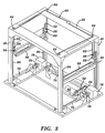
Referring additionally to Fig. 3, the support frame 32 has four
vertical support beams 46 provided with guide tracks 48 for
guiding the tables while being raised or lowered. Each table has
four rotatable guide wheels 50 (only two shown as viewed in Fig.
2) which ride in the guide tracks 48 at the corners of each table.
The table support mechanism 44 comprises four vertical shafts 52
with bearing mounts 54 at the upper ends of each shaft 52. The
shafts 52 are rotatable relative to the bearing mounts 54 which
are attached to the topside of the support frame 32. The support
frame 32 has bores (not shown) which the shafts pass through to
extend downward to the tables 34, 36. At the lower ends of the
shafts 52 are support bars 56 which protrude horizontally outward
from the shaft 52 at a right angle therefrom, and lower bearing
mounts 58 attached to the four vertical support beams 46. In an
inactive position, the support bars 56 face outward and away from
the tables, as shown in Fig. 3. A linkage 60 connecting the shafts
52 transmits rotary motion from a drive motor 62 to rotary plates
64 fixed to the tops of each shaft 52 and to the shaft of the
drive motor 62. Upon a predetermined rotation by the drive motor
62, the linkage 60 connecting the rotary plates causes the four
shafts 52 to rotate 90 degrees, positioning the horizontal support
bars 56 facing inward toward the tables, in the active position as
in Fig. 2. The support bars 56 are in position to support the
tables 34 above the cassette 24 to be accessed by the picker 28.
The elevator mechanism 40 comprises a chain drive system having
four chain drives 66, one mounted on each support beam 46. Two
rotatable sprockets 68, 70 are mounted on each support beam 46 in
an upper and lower position to cooperate with the chains 66 and
transmit rotary motion of the sprockets 68, 70 into linear motion
of the chains 66. The lower sprockets 70 are attached to two
horizontal shafts 72 which transmit rotary motion from a main
drive shaft 74 through several gear boxes 76 and couplings 78. The
main drive shaft 74 is powered by a drive motor 80 through a belt
82 and pulley 84 connection.
The brace 38 is connected to the chains 66 on the inner sides of
the support beams 46 so that upon rotation of the drive motor 80,
the chain drive system raises or lowers the brace 38, the
lowermost table 36, and any upper tables 34 resting thereon which
are not supported by the table support mechanism 44 at the time.
Referring now to Fig. 4, the picker 28 is shown supported on
parallel rails 90 which are fixed to the interior of the engine
compartment 20 (Fig. 1). Complementary rails 92 are mounted inside
of the handler 18 as shown cross section in Fig. 2 and
isometrically in Fig. 3, allowing the picker to move smoothly
between the engine 20 and handler 18. The rails 92 inside the
handler are secured to the support beams 46 of the handler frame
32. The picker 28 has a carriage 94 which is supported on the
rails (90 or 92 depending on whether the handler is in the engine
or the handler respectively) by three guide wheels 96 which engage
the rails 90 (or 92) on each side of the carriage 94. Also two
friction wheels 98 engage the rails 90 (or 92). The friction
wheels 98 are driven by a motor 100 mounted on the carriage 94
through a connection to a drive shaft 102 and a belt and pulley
mechanism 104 on each side of the carriage 94. The motor 100
operates in two directions to effectively propel the picker
carriage 94 in forward and reverse from the engine compartment 20
to the handler 18. The carriage 94 supports three rows 106, 108,
110 of suction cups and an associated vacuum manifold 112 and
vacuum tubing (not shown) between the manifold 112 and the three
rows 106, 108, 100 of suction cups. The suction cups 114 are
mounted on spring loaded fittings 116 to allow compression of the
suction cups 114 against a plate during picking to ensure
attachment of the plate to the picker 28. The first row 106 of
suctions cups that extends the furthest into the handler 18 is
pivotable with respect to the carriage 94. An eccentric drive 118
and linkage 120 pivots the first row 106 of suction cups in a
ÒpeelingÓ motion. The eccentric 118 is driven by a motor 122
mounted on the carriage 94 to break or peel the edge of the plate
being picked away from the stack. The middle row 108 of suction
cups remains fixed with respect to the picker carriage 94. The
third row 110 of suction cups slides out from the middle row 108
of suction cups. Two circular rails 124, 126 are mounted for
sliding through complementary bearings (not shown) in the carriage
body 94 on the both sides of the picker 28. On the right side of
the picker viewed in Fig. 4, the circular rail 126 has a friction
drive wheel (not shown) is in driving contact with the circular
rail 126. The drive wheel is driven by a drive motor 128 through a
belt and pulley mechanism (not shown), all of which are mounted to
the carriage body 94 so as to transmit rotary motion of the drive
wheel into linear motion of the circular rails 126, 124 relative
to the carriage body 94. The third row 110 of suction cups being
movable relative to the other rows 106, 108 of suction cups
expands the overall size of the picker 28 and the coverage area of
the suction cups 114 to accommodate for various sized plates.
Fig. 5 illustrates a simplified top view of the picker 28
positioned over a cassette 24 in the handler. The first row 106 of
suction cups 114 is positioned near an inner edge 130 of the
cassette 24 against which the plates are referenced regardless of
the plate size. Four different plates having different sizes are
depicted by dashed lines and are indicated as plates A, B, C, and
D. Plate A is the smallest plate and the middle row 108 of suction
cups of the picker 28 is positioned near the opposite edge 132 of
plate A from the reference edge 130. The middle row 108 has a
fixed position relative to the first row 106 (excepting that the
first row is pivotable) to pick up plate A without the use of the
third row 110 of suction cups. The third row 110 is shown in an
extended position by solid lines, at the far edge 134 of the
largest plate D opposite from the reference edge 130. The third
row 110 of suction cups is also shown by dashed lines in a non-extended
position. The third row 110 of suction cups is used to
expand the size of the picker 28 to cover the areas for various
size plates, such as B, C, and D, larger than the smallest plate A
and smaller than or equal to the largest plate D, as indicated by
arrow 136. Arrow 138 shows the relative movement of the picker 28
including all three rows 106, 108, 110 of suction cups 114 with
respect to the handler cassette 24 and the engine.
Referring now to Fig. 6, the slip sheet removal mechanism is
generally indicated as 25. The mechanism 25 is for the purpose of
preventing a slip sheet 140 from sticking to the bottom of a plate
142 which is attached to the picker 28, securing the slip sheet
140 on the top of the stack of plates in a cassette 24 to the slip
sheet removal mechanism 25, and subsequently completely removing
the slip sheet 140 from the stack of plates in the cassette 24.
The mechanism 25 comprises a plurality of suction tubes 144
mounted on a first pivotable shaft 146, an optional peeler air
blast 148, a plurality of fingers 150 mounted on a second pivoting
shaft 152, a plurality of nip wheels 154 mounted on a third
pivoting shaft 156 (only one of each seen in drawing due to side
view), and a rotatably driven roller 158 positioned below the nip
wheels 154 which are in rolling contact during part of the slip
sheet removal process, to be described hereinafter. The suction
tubes 144 are fixed to the pivoting shaft 146 to pivot upon being
driven by motor 160 through a drive belt and pulley connection
162. The fingers 150 are fixed to pivoting shaft 152 which is
driven by a similar drive connection to a motor (not shown). The
nip wheels 154 are each mounted to an extension arm 164 which is
attached to a bracket 166 mounted on the pivoting shaft 156. The
extension arm 164 is spring loaded at the connection to the
bracket to allow for the extension arm 164 to pivot or give
slightly while pressure is applied between the nip wheel 154 and
the roller 158. The shaft 156 is rotated in forward and reverse by
the drive motor 168 through a drive belt and pulley connection
170. The roller 158 is driven by a motor 172 also through a belt
and pulley connection 174. It will be understood by those skilled
in the art that equivalent means for rotating the pivoting shafts
146, 152, 154, and rotating roller 158, may be substituted
therefor without departing from the spirit of the invention. The
driven shafts and motors for driving the shafts are all mounted to
a mounting bracket 176 which is connected to the support beams 46
of the handler 18. Operation of the slip sheet removal mechanism
25 will be described hereinafter.
Referring now to Fig. 7 and Fig. 8, a cassette 24 for loading into
the plate handler is shown. The cassette has a removable cover
180, which is removed and replaced in a vertical direction
relative to a rectangular bottom container 182 as indicated by
arrows. The bottom container 182 comprises a base plate 184
surrounded by four aluminum side extrusions 186. The extrusions
186 are attached at the four 90 degree corners by spring clips and
adhesive (not shown). The base plate 184 is contained within a
slot 188 in the edge of each extrusion 186 and is held in place
with an adhesive on the top side 190 of the base plate 184 and a
piece of continuous round flexible urethane belting 192 on the
bottom side of the base plate 184. The round belting 192 is
retained in a thin groove 194 provided in the extrusion 186.
Three channels 196 (one shown) are fastened to the bottom side of
the base plate 184. The channels 196 act as reinforcing stiffeners
for the bottom container 182, and also are housings for three
locator bars 198. Each locator bar 198 is attached within a
channel 196 by an adhesive. An adjustable stop 200 is provided on
each locator bar 198 to slide along the locator bar and be
fastened to a set position by a lock screw 202 which screws into
holes 204 drilled into the locator bars 198. The three adjustable
stops 200 locate and secure a stack of plates 26 against several
reference blocks 206 fastened to the side extrusions 186. The
adjustable stops 200 allow multiple sizes of plates 26 to be held
against the reference blocks 206 within a single bottom container
182. The base plate 184 is provided with embossed areas 208 for
the reference blocks 206 to be set within, which prevents the
plates referenced against the reference blocks 206 from sliding
between the reference block 206 and the base plate 184 and
maintaining alignment of the plates with respect to the reference
block 206.
The cover 180 comprises a top plate 210 and four side extrusions
212 surrounding the top plate 210. The extrusions 212 are fastened
together at the four corners of the top plate 210 by spring clips
and adhesive (not shown). The top plate is secured to a ledge
portion 214 of the extrusions 212 by an adhesive. Two of the four
side extrusions have a handle portion 216 formed in the extrusion
212 which cooperate with hooks on the undersides of the cassette
tables in the handler to remove and replace the cassette cover (to
be described hereinafter). The inside of the top plate 210 has a
layer of foam 218 attached, to ensure that the plates on the top
of a full stack of plates 26 do not slide over the tops of the
reference blocks 206 during loading of a cassette 24 into the
handler 18. The cover 180 and the bottom container 182 are
constructed are constructed from light proof materials, so that
when the plates are enclosed within a covered cassette, there is
no exposure of the light sensitive plate contained within the
cassette. The attachment area between the bottom extrusions 186
and the cover extrusions 212 has magnetic strips 220 which ensure
the cover 180 is attached securely to the bottom container 182 and
that no light will enter the cassette 24 during handling.
The side extrusions 186 are provided with a beveled portion 230
which aid in the loading of the cassette 24 into the plate handler
18. The handler 18 has a loading platform 232 shown in Fig. 2,
extending horizontally from the vertical beams 46 of the handler.
The loading platform 232 has rows of grooved wheels 234 mounted
for rotation within the loading platform 232. The grooved wheels
234 cooperate with the beveled portion 232 of the side extrusions
186 of the cassette 24 during loading and serve to register the
cassettes in a reference position within the handler. All tables
34 and 36 within the handler are also provided with the rows of
grooved wheels to facilitate smooth and easy loading of the
cassette from the loading platform onto the support tables in the
handler, while maintaining the cassette in register. The beveled
portions 230 cooperated with the V-grooved surface 236 of the
grooved wheels 234 on opposite outer sides of the cassette 24 for
proper alignment. The cassette is designed to align the plates
inside the cassette against the reference blocks provided on the
interior of the cassette, and also register the cassette into a
reference position within the handler, as shown in Fig. 5,
regardless of the plate size contained in the cassette. The
parallel rails 92 in the handler are fixed relative to the wheels
of the selected table in the access position. This ensures the
registration of the plates within the cassette relative to the
rails 92, and the registration is transferred to the complementary
rails 90 in the engine compartment, and thereby the plate is
delivered in register into the engine from the handler.
Additional locator stops 238 are provided on each table to assist
in registering the cassette 24 in the loading direction so that
the cassette 24 is pushed into the handler 18 along the grooved
wheels 234 of the table 36, but only to a predetermined location
so that the cassette 24 is registered with respect to two
dimensions and to the picker rails 92. These additional locator
stops 238 are spring loaded and are located between the grooved
wheels 234 within each row of grooved wheels on a table 36. The
stops 238 contact an underside 240 of the side extrusions 186
while the cassette 24 is being loaded, and when the stop 238 comes
into contact with a recess (not shown) formed in the underside of
the extrusion, the spring force behind the stop 238 forces the
stop into the recess and locks the cassette 24 the predetermined
on the table. The wheels 234 register the cassette with respect to
the two reference blocks 206 on one side of the cassette, while
the locator stops 238 within the rows of the wheels 234 register
the cassette 24 with respect the third, alone reference block 206
on the neighboring side of the cassette. Then the plates are
registered in a known location relative to the picker, as depicted
in Fig. 5.
The loading platform can be incorporated into the design of the
doors and covers for enclosing the handler in a light tight
environment. The loading platform can function both as a door into
the cassette loading area, and as the loading platform. This is
accomplished by providing an attachment hinge on the handler frame
for the loading table to pivot between the two functional
positions. The loading table is pivoted up for a closed door
position, and down and horizontally as shown in the figure for an
open, cassette loading position.
Cassettes loaded into the handler house the plates. At any one
time, a cassette holds only like plates (same type, gauge, size,
etc.). Typically, there is a maximum of 50 plates of 0.012" gauge,
75 plates of 0.008" gauge, or 100 plates of 0.006" gauge, in a
single cassette. There are several distinct cassette sizes. A
cassette of a specific size holds a range of plate sizes inside,
however only one size plate is loaded into a cassette at any one
time. Fillers or guides are used to take-up the space between
plate and cassette boundaries. The reference position of the
plates within the cassette is described above with reference to
Fig. 5. Packaging of plates within a cassette is related to both
handler operation and cassette transportability. There may be a
mix of cassettes in the handler (two, three or four cassettes).
All cassettes can be different from each other, in that each
houses a distinct set of plate characteristics (type, size, gauge,
etc.) There may be instances where some or all cassettes inside
the handler have the same plate characteristics.
Now, with reference to all the Figures, the method for using the
plate handler 18 and picker 28 will be described. The primary
function of the handler 18 is to position a required plate on
demand in an access position for the picker 28, which picks and
delivers the required plate to the engine 22. Once the handler 18
receives a request from the engine 22 for a specific plate, the
following actions take place in the handler, in cooperation with
the engine 20. The picker 28 begins in the home position within
the engine 20. The slip sheet removal mechanism 25 is positioned
with the suction tubes 144, fingers 150, and nip wheels 154
retracted (as shown in dotted lines for the suction tubes and nip
wheels in Fig. 6) to clear the path of the tables 34, 36 for
repositioning by the elevator mechanism 40. The elevator mechanism
40 moves the brace 38, lower table 36, and upper tables 34
supported thereon, if any, to a cover removal/replacement
position. In the cover removal/ replacement position, the selected
table 36 is located directly below the table 34 supported by the
support bars 56 of the table support mechanism 44. Hooks on the
bottom of the supported table 34 engage the cover 180 of the
selected cassette 24 for either removal or replacement, so that
the cover 180 is separated from or rejoined with the selected
cassette 24.
In Fig. 2, the cover removal/replacement position for the lower
table 36 is at a position where the open cassette 24 on the lower
table 36 contacts the cover 180 supported by the table 34
immediately above the lower table 36 held by the support bars 56.
When the selected cassette 36 is in the cover removal/replacement
position, the upper tables 34 are all then supported by the brace
38. Then the support bars 56 and shafts 52 are turned 90 degrees
by means of the linkage 60 and drive motor 64. Once the support
bars 56 are retracted from the path of motion of the tables 34,
36, the elevator mechanism 40 moves to the cover
removal/replacement position for the next selected table and
cassette. The table support mechanism 44 moves the support bars 56
into the supporting position underneath the table directly above
the selected cassette 24. The elevator mechanism 40 then moves the
selected table down thereby separating the cover 180 of the
selected cassette 24 from the selected cassette 24 so that the
picker can access the plates 26 contained within the cassette 24.
The picker 28 is then moved from the home position in the engine
20 into the handler 18 along the rails 90 and 92. Depending on the
size of the plate in the selected cassette 24 the picker 28
adjusts the third row 110 of suction cups relative to the middle
row 108 of suction cups to accommodate for various plate sizes, if
necessary (Fig. 5). The elevator mechanism 40 moves the selected
cassette 24 and plates therein upward to come into contact with
the suction cups 114 on the picker 28 (Figs. 4 and 6). The suction
cups 114 retract into the spring loaded fittings 116 to
accommodate for variations in the stack height of the plates 26 in
the cassettes 24, as the elevator 40 moves the cassette 24 up to
the picking position which is at a set vertical height relative to
the picker rails 90b, 92b. Therefore for a maximum stack height of
a full stack of plates, the suction cups 114 compress against the
spring loaded fittings 116 and retract a length into the fittings,
and for a depleted stack of plates, the suction cups 114 compress
against the spring loaded fittings and retract substantially the
same length minus the height of the stack depletion. The spring
loaded fittings 116 also ensure that the plate and the suction
cups 114 make contact to secure the plate onto the picker 28.
After the plate is attached to the picker 28 by the vacuum
suction, the first row 106 of suction cups on the picker 28 is
pivoted upward, peeling back the edge of the plate 142 and
creating a gap between the plate 142 and the slip sheet 140
underneath.
The slip sheet removal mechanism 25 activates the peeler air flow
148, and the fingers 150 are pivoted into position to hold down
the edge of the slip sheet 140 while the elevator mechanism 40
lowers the cassette 24 to a slip sheet removal position. The
peeler air blast 148 remains on while the cassette 24 moves
downward to separate the slip sheet 140 from the bottom of the
plate 142 being picked by the picker 28, which may stick to the
plate due to electrostatic charge. The fingers 150 are pivoted
away from the slip sheet 140 and the suction tubes 144 are pivoted
into position above the slip sheet edge. The suction cups on the
ends of the suction tubes are compliant and flexible so that when
the vacuum is applied and contact is made between a suction cup
and the slip sheet, the slip sheet material is drawn into the
suction cup and the separation of the slip sheet from the plate
below it is initiated. The compliant suction cup deforms to break
the slip sheet away from the lower plate as typically an
attractive force exists between the slip sheet and the plate. This
is also an important step in the process of removing the slip
sheet because the slip sheet may be a porous material and the
vacuum applied through the suction tubes can pass through the slip
sheet material and be applied to the plate below, which is
undesirable when attempting to remove the slip sheet. The selected
cassette 24 is elevated to bring the slip sheet 140 into contact
with the suction tubes 144 while the vacuum is on. The suction
tubes 144 pivot upward slightly to break the adhesion of the slip
sheet 140 to the plate below. The elevator 40 then moves the
selected cassette 24 downward from the slip sheet removal
mechanism 25 and the suction tubes 144 pivot back downward to the
roller 158 with the slip sheet 140 attached. The vacuum for the
suction tubes 144 is turned off and the slip sheet 140 is released
to the rotating roller 158 to pull the slip sheet 140 away from
the stack. The nip wheels 164 pivot from the position shown in
solid lines to the position shown in dotted lines to cooperate
with the roller 158 and remove the slip sheet 140. A sensor (not
shown) indicates that the removal of the slip sheet 140 is
completed and the rotating roller 158 is then halted. Meanwhile
the picker 28 lowers the first row 106 of suction cups from the
peeling position, and the picker 28 travels back into the engine
22 to the home position. For the next plate to be selected by the
picker 28, the steps are partially repeated if the same cassette
24 is being picked from, or the steps are repeated from the
beginning of the sequence for another cassette.
In order to load cassettes into the handler, the following method
steps occur in conjunction with the plate handler apparatus and
the workflow software as described previously. The handler has
sensors positioned appropriately (not shown) to monitor the level
of the plates contained in each cassette. Additionally the handler
has the capability of knowing the types of plates available so
that when a plate needed by the engine is not available, or upon a
sensor detecting an empty cassette, a signal is communicated to
the engine and the operator is alerted through the operator
control terminal 30.
The picker 28 is returned (if not already there) to begin in the
home position within the engine 20. The slip sheet removal
mechanism 25 is positioned with the suction tubes 144, fingers
150, and nip wheels 154 retracted (as shown in dotted lines for
the suction tubes and nip wheels in Fig. 6) to clear the path of
the tables 34, 36 for repositioning by the elevator mechanism 40.
The elevator mechanism 40 moves the brace 38, lower table 36, and
upper tables 34 supported thereon, if any, to the cover
removal/replacement position previously described. Then the
support bars 56 and shafts 52 are turned 90 degrees by means of
the linkage 60 and drive motor 64. Once the support bars 56 are
retracted from the path of motion of the tables 34, 36, the
elevator mechanism 40 moves to the cassette loading position for
the selected table and cassette needing replacement. The cassette
loading position is located where the selected table is adjacent
to the loading platform 232 shown in Fig. 2 extending out from the
handler 18 to support the cassette 24 to slide horizontally
between the selected table and the loading platform 232 during
loading and unloading. Covers and doors (not shown) are provided
to enclose the entire handler frame to maintain the cassette in a
light tight environment. The doors are provided to access the
interior of the handler and at this time the door locks are
released to allow operator access. Then the empty cassette is
removed by sliding the cassette out horizontally in along the path
formed by the grooved wheels in the selected table and the loading
platform, and then the cassette is either reloaded or replaced
with another cassette. The cassette presence is monitored by
sensors. After detecting the cassette on the selected table, the
handler waits for the doors to be closed and then the door locks
are activated. The elevator moves up to the cover
removal/replacement position for the selected cassette and normal
operation is resumed.
It will be understood that the preferred embodiment of the system
described herein being a platesetter for imaging aluminum plates,
can be used also with polyester plates, can be modified to perform
as a proofing device rather than a platesetter, such as in
commonly owned, pending US application 08/496,714, entitled
ÒElectronic Prepress System With Multi-Function Thermal Imaging
Apparatus,Ó hereby incorporated by reference. Additionally the
apparatus described herein is applicable to production of
thermally recorded printing plates as well as photosensitive
lithographic printing plates recorded by light exposure, with
various modification to the system's processing and imaging
components, as appreciated by those familiar with the art.
While this invention has been described in terms of various
preferred embodiments, those skilled in the art will appreciate
that various modifications, substitutions, omissions and changes
may be made without departing from the spirit thereof.
Accordingly, it is intended that the scope of the present
invention be limited solely by the scope of the following claims,
including equivalents thereof.