EP0825064A1 - Apparatus for checking blind spots of vehicle - Google Patents
Apparatus for checking blind spots of vehicle Download PDFInfo
- Publication number
- EP0825064A1 EP0825064A1 EP97114530A EP97114530A EP0825064A1 EP 0825064 A1 EP0825064 A1 EP 0825064A1 EP 97114530 A EP97114530 A EP 97114530A EP 97114530 A EP97114530 A EP 97114530A EP 0825064 A1 EP0825064 A1 EP 0825064A1
- Authority
- EP
- European Patent Office
- Prior art keywords
- vehicle
- taken
- graphic information
- main body
- image sensor
- Prior art date
- Legal status (The legal status is an assumption and is not a legal conclusion. Google has not performed a legal analysis and makes no representation as to the accuracy of the status listed.)
- Granted
Links
- 238000010586 diagram Methods 0.000 description 4
- 238000009434 installation Methods 0.000 description 4
- 230000002349 favourable effect Effects 0.000 description 1
- 238000000034 method Methods 0.000 description 1
- 229920003023 plastic Polymers 0.000 description 1
Images


Classifications
-
- B—PERFORMING OPERATIONS; TRANSPORTING
- B60—VEHICLES IN GENERAL
- B60R—VEHICLES, VEHICLE FITTINGS, OR VEHICLE PARTS, NOT OTHERWISE PROVIDED FOR
- B60R1/00—Optical viewing arrangements; Real-time viewing arrangements for drivers or passengers using optical image capturing systems, e.g. cameras or video systems specially adapted for use in or on vehicles
- B60R1/20—Real-time viewing arrangements for drivers or passengers using optical image capturing systems, e.g. cameras or video systems specially adapted for use in or on vehicles
- B60R1/22—Real-time viewing arrangements for drivers or passengers using optical image capturing systems, e.g. cameras or video systems specially adapted for use in or on vehicles for viewing an area outside the vehicle, e.g. the exterior of the vehicle
- B60R1/23—Real-time viewing arrangements for drivers or passengers using optical image capturing systems, e.g. cameras or video systems specially adapted for use in or on vehicles for viewing an area outside the vehicle, e.g. the exterior of the vehicle with a predetermined field of view
-
- B—PERFORMING OPERATIONS; TRANSPORTING
- B60—VEHICLES IN GENERAL
- B60R—VEHICLES, VEHICLE FITTINGS, OR VEHICLE PARTS, NOT OTHERWISE PROVIDED FOR
- B60R2300/00—Details of viewing arrangements using cameras and displays, specially adapted for use in a vehicle
- B60R2300/10—Details of viewing arrangements using cameras and displays, specially adapted for use in a vehicle characterised by the type of camera system used
- B60R2300/105—Details of viewing arrangements using cameras and displays, specially adapted for use in a vehicle characterised by the type of camera system used using multiple cameras
-
- B—PERFORMING OPERATIONS; TRANSPORTING
- B60—VEHICLES IN GENERAL
- B60R—VEHICLES, VEHICLE FITTINGS, OR VEHICLE PARTS, NOT OTHERWISE PROVIDED FOR
- B60R2300/00—Details of viewing arrangements using cameras and displays, specially adapted for use in a vehicle
- B60R2300/30—Details of viewing arrangements using cameras and displays, specially adapted for use in a vehicle characterised by the type of image processing
- B60R2300/303—Details of viewing arrangements using cameras and displays, specially adapted for use in a vehicle characterised by the type of image processing using joined images, e.g. multiple camera images
-
- B—PERFORMING OPERATIONS; TRANSPORTING
- B60—VEHICLES IN GENERAL
- B60R—VEHICLES, VEHICLE FITTINGS, OR VEHICLE PARTS, NOT OTHERWISE PROVIDED FOR
- B60R2300/00—Details of viewing arrangements using cameras and displays, specially adapted for use in a vehicle
- B60R2300/80—Details of viewing arrangements using cameras and displays, specially adapted for use in a vehicle characterised by the intended use of the viewing arrangement
- B60R2300/802—Details of viewing arrangements using cameras and displays, specially adapted for use in a vehicle characterised by the intended use of the viewing arrangement for monitoring and displaying vehicle exterior blind spot views
-
- B—PERFORMING OPERATIONS; TRANSPORTING
- B60—VEHICLES IN GENERAL
- B60R—VEHICLES, VEHICLE FITTINGS, OR VEHICLE PARTS, NOT OTHERWISE PROVIDED FOR
- B60R2300/00—Details of viewing arrangements using cameras and displays, specially adapted for use in a vehicle
- B60R2300/80—Details of viewing arrangements using cameras and displays, specially adapted for use in a vehicle characterised by the intended use of the viewing arrangement
- B60R2300/8066—Details of viewing arrangements using cameras and displays, specially adapted for use in a vehicle characterised by the intended use of the viewing arrangement for monitoring rearward traffic
Definitions
- the present invention relates to an apparatus for checking the blind spots of a vehicle.
- the areas just and ahead and behind the vehicle are also blind spots, and these blind spots must be checked when the vehicle moves out. This job is performed by the driver before getting into the vehicle, but no check can be made from that point until the vehicle actually moves out, and this is a cause of some apprehension when moving out.
- An object of the present invention is to provide an apparatus for checking the blind spots of a vehicle, with which the situation in the blind spots of the above-mentioned vehicle can be checked easily and reliably.
- the apparatus comprises an apparatus main body , in which graphic information is taken in from both sides of the vehicle by the above-mentioned image sensors, and a display apparatus, which is installed inside the vehicle and displays the graphic information taken in by the above-mentioned image sensors.
- an image sensor that faces forward is furnished to the above-mentioned apparatus main body, so that graphic information from in front of the vehicle will also be taken in by the image sensor.
- the situation in front can also be checked when moving out, there will be no unchecked periods between the time the driver gets into the vehicle and the time the vehicle moves out, and any apprehension that would otherwise be experienced upon moving out is alleviated. Also, when a vehicle is taken from an alley or the like onto a main street, graphic information from in front of the vehicle up until the front end of the vehicle (the apparatus main body) reaches the main street will be displayed on the display apparatus, and this also makes driving extremely easy.
- the situation in front of the vehicle must be directly checked up until the apparatus main body reaches the main street if only graphic information from both sides of the vehicle is displayed on the display apparatus, but if the situation in front of the vehicle can be checked on the display apparatus before the apparatus main body reaches the main street, then the vehicle can be driven while the driver's eyes are on the image of the display apparatus.
- the blind spot checking apparatus of the present invention comprises an apparatus main body, which is installed at the front side of the vehicle on the opposite side from the steering wheel, and in which rearward graphic information along the side of the vehicle is taken in by an image sensor, and a display apparatus, which is installed inside the vehicle and displays the graphic information taken in by the above-mentioned image sensor.
- an image sensor is installed facing rearward on the front side of the vehicle opposite the side with the steering wheel.
- one or two additional image sensors are added and installed on one or both sides of the vehicle.
- the situation on the side of the vehicle on the opposite side from the steering wheel, and the situation to the side of the vehicle on the opposite side from the steering wheel can be checked by installing one wide-angle image sensor facing in between to the rear and to the side of the vehicle.
- the blind spot checking apparatus of the present invention comprises an apparatus main body, which is installed at the top rear portion of the vehicle on the side opposite from the steering wheel, and in which the side portion viewed' along one side of the vehicle and the rear portion viewed along the rear of the vehicle are taken in by an image sensor, and a display apparatus, which is installed inside the vehicle and displays the graphic information taken in by the above-mentioned image sensor.
- two image sensors may be installed facing in each direction, but graphic information from both directions can also be taken in by installing a single image sensor facing downward and in between these directions.
- the image sensor should be installed facing downward and tilted slightly to the front of the vehicle.
- the situation at the side portion viewed along one side of the vehicle and at the rear portion viewed along, the rear of the vehicle can be checked with ease, and the area near the rear wheel of the vehicle can be easily checked during a turn in the direction on the opposite side of the vehicle from the steering wheel, so there is no danger of the rear wheel running over a bicycle or the like that is on the left side of the vehicle, nor is there any danger of running up onto the curb or the like. Also, since the blind spot to the rear can be checked when backing up, there is no unchecked period between the time the driver gets into the vehicle and the time the vehicle starts backing up, which eliminates the apprehension that would otherwise be experienced.
- the other rear side end viewed along the rear of the vehicle is also taken in by the image sensor of the above-mentioned apparatus main body.
- CCD Charge Coupled Device
- the graphic information taken in by the image sensors is displayed on a split display screen of a display apparatus by a known method.
- the orientation of the image sensors is adjusted as needed up and down and to the left or right.
- graphic information is taken in by the image sensors that check the situation to the side such that about half of the field of vision is taken up by the vehicle, and the other half by a view of the surroundings to the side of the vehicle.
- the installation angle should be adjusted so that the orientation of the image sensors is moved slightly away from the vehicle.
- the orientation of the image sensor should be pointed slightly downward in order to obtain graphic information from close to the bumper.
- the graphic information taken in by a plurality of image sensors is subjected to suitable image processing, and the required portion of the range is displayed as a split screen on a display apparatus.
- the surface area, positioning, and so on of the displayed images are determined as desired.
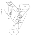
- FIG 1 illustrates a practical example in which an apparatus main body 10 is installed in the middle of the front bumper 2 of a vehicle 1 having a hood.
- This apparatus main body 10 comprises three image sensors 11, 12, and 13.
- the image sensors 11 and 12 are installed facing to the left and right of the vehicle 1, and the image sensor 13 is installed facing to the front of the vehicle 1.
- Graphic information A1 and A2 over a field of vision of 70 degrees is taken in by the image sensors 11 and 12, and graphic information B over a field of vision of 140 degrees is taken in by the image sensor 13.
- the graphic information A1, A2, and B taken in by the various image sensors 11, 12, and 13 is subjected to suitable image processing, and the required portions of the range are displayed on a split screen as shown in Figure 3 on the display component of a display apparatus 14 installed in the interior of the vehicle 1.
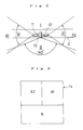
- FIG 4 illustrates a practical example in which an apparatus main body 20 is installed on the side end (left side) on the opposite side from the steering wheel 5 on the front bumper 4 of a van type of vehicle 3.
- This apparatus main body 20 comprises two image sensors 21 and 22.
- the image sensor 21 is installed facing to the rear along the side of the vehicle 3, and the image sensor 22 is installed facing to the left side of the vehicle.
- Graphic information C over a field of vision of 70 degrees is taken in by the image sensor 21, and graphic information D over a field of vision of 70 degrees is taken in by the image sensor 22.
- the graphic information C and D taken in by the image sensors 21 and 22 is subjected to image processing as needed, and the required portions of the range are displayed on a split screen as shown in Figure 6 on the display component of a display apparatus 23 installed in the interior of the vehicle 3.
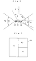
- FIG. 7 illustrates a practical example in which an apparatus main body 30 is installed on the rear end upper portion on the opposite side from the steering wheel on a van type of vehicle 6.
- This apparatus main body 30 comprises three image sensors 31, 32, and 33.
- the image sensor 31 is installed facing downward from the vehicle 6 and tilted slightly to the front of the vehicle, and the image sensors 32 and 33 are installed facing to both sides of the vehicle 6.
- Graphic information E over a field of vision of 140 degrees of the portion along the rear and the portion along the side of the vehicle 6 is taken in by the image sensor 31, and graphic information F1 and F2 over a field of vision of 70 degrees is taken in by the image sensors 32 and 33.
- the graphic information E, F1, and F2 taken in by the image sensors 31, 32, and 33 is subjected to image processing as needed, and the required portions of the range are displayed on a split screen as shown in Figure 9 on the display component of a display apparatus 34 installed in the interior of the vehicle 6.
- two image sensors 31 and 33 can be installed at the rear end upper portion 7 of the vehicle, and the graphic information taken in by these image sensors 31 and 33 can be displayed on a split screen as shown in Figure 10 on the display component of the display apparatus 34.
- the display apparatus of a navigation system, a television, or the like can be used as the display apparatus in the present invention.
Abstract
Description
Claims (6)
- A blind spot checking apparatus for a vehicle characterized by comprising:image sensors facing to both sides of the vehicle are installed at the front of the vehicle;an apparatus main body, in which graphic information is taken in from both sides of the vehicle by the above-mentioned image sensors; anda display apparatus, which is installed inside the vehicle and displays the graphic information taken in by the above-mentioned image sensors.
- The blind spot checking apparatus for a vehicle as defined in Claim 1, wherein an image sensor that faces forward is furnished to the above-mentioned apparatus main body, so that graphic information from in front of the vehicle will also be taken in by said image sensor.
- A blind spot checking apparatus for a vehicle, wherein an apparatus main body, which is installed at the front side of the vehicle on the opposite side from the steering wheel, and in which rearward graphic information along the side of the vehicle is taken in by an image sensor, and a display apparatus, which is installed inside the vehicle and displays the graphic information taken in by the above-mentioned image sensor.
- The blind spot checking apparatus for a vehicle as defined in Claim 3, wherein graphic information from the side of the vehicle is also taken in by the image sensors of the apparatus main body.
- A blind spot checking apparatus for a vehicle, characterized by comprising:an apparatus main body, which is installed at the top rear portion of the vehicle on the side opposite from the steering wheel, and in which the side portion [viewed along one side of the vehicle and the rear portion viewed along the rear of the vehicle are taken in by an image sensor; anda display apparatus, which is installed inside the vehicle and displays the graphic information taken in by the above-mentioned image sensor.
- The blind spot checking apparatus for a vehicle as defined in Claim 5, wherein graphic information to the sides viewed along the rear of the vehicle is also taken in by the image sensor of the above-mentioned apparatus main body.
Applications Claiming Priority (4)
| Application Number | Priority Date | Filing Date | Title |
|---|---|---|---|
| JP8241110A JPH1059068A (en) | 1996-08-23 | 1996-08-23 | Dead angle confirmation device for vehicle |
| JP241110/96 | 1996-08-23 | ||
| JP24111096 | 1996-08-23 | ||
| US08/915,236 US5959555A (en) | 1996-08-23 | 1997-08-20 | Apparatus for checking blind spots of vehicle |
Publications (2)
| Publication Number | Publication Date |
|---|---|
| EP0825064A1 true EP0825064A1 (en) | 1998-02-25 |
| EP0825064B1 EP0825064B1 (en) | 2003-06-25 |
Family
ID=26535095
Family Applications (1)
| Application Number | Title | Priority Date | Filing Date |
|---|---|---|---|
| EP97114530A Expired - Lifetime EP0825064B1 (en) | 1996-08-23 | 1997-08-22 | Apparatus for checking blind spots of vehicle |
Country Status (3)
| Country | Link |
|---|---|
| US (1) | US5959555A (en) |
| EP (1) | EP0825064B1 (en) |
| JP (1) | JPH1059068A (en) |
Cited By (6)
| Publication number | Priority date | Publication date | Assignee | Title |
|---|---|---|---|---|
| EP1018839A2 (en) | 1999-01-08 | 2000-07-12 | Volkswagen Aktiengesellschaft | Method and apparatus for inspecting the rear observation space of a vehicle |
| GB2395177A (en) * | 2002-11-16 | 2004-05-19 | Edward Peter Ellis | Imaging system providing lateral images from the front bumper of a vehicle |
| EP1434441A1 (en) * | 2001-09-28 | 2004-06-30 | Matsushita Electric Industrial Co., Ltd. | Drive support display apparatus |
| WO2004059968A2 (en) * | 2002-12-20 | 2004-07-15 | Bendix Commercial Vehicle Systems Llc | Multiple camera system on single monitor display |
| GB2411533A (en) * | 2004-02-24 | 2005-08-31 | Shih-Hsiung Li | Monitoring peripheral conditions for vehicles |
| EP2166766A1 (en) * | 2008-09-18 | 2010-03-24 | MAGNETI MARELLI SISTEMI ELETTRONICI S.p.A. | On-board system for auxillary viewing of the surroundings of a vehicle |
Families Citing this family (174)
| Publication number | Priority date | Publication date | Assignee | Title |
|---|---|---|---|---|
| US5670935A (en) | 1993-02-26 | 1997-09-23 | Donnelly Corporation | Rearview vision system for vehicle including panoramic view |
| US6822563B2 (en) | 1997-09-22 | 2004-11-23 | Donnelly Corporation | Vehicle imaging system with accessory control |
| US5910854A (en) | 1993-02-26 | 1999-06-08 | Donnelly Corporation | Electrochromic polymeric solid films, manufacturing electrochromic devices using such solid films, and processes for making such solid films and devices |
| US5877897A (en) | 1993-02-26 | 1999-03-02 | Donnelly Corporation | Automatic rearview mirror, vehicle lighting control and vehicle interior monitoring system using a photosensor array |
| US5668663A (en) | 1994-05-05 | 1997-09-16 | Donnelly Corporation | Electrochromic mirrors and devices |
| US6891563B2 (en) | 1996-05-22 | 2005-05-10 | Donnelly Corporation | Vehicular vision system |
| US7655894B2 (en) | 1996-03-25 | 2010-02-02 | Donnelly Corporation | Vehicular image sensing system |
| US6172613B1 (en) | 1998-02-18 | 2001-01-09 | Donnelly Corporation | Rearview mirror assembly incorporating vehicle information display |
| US6124886A (en) | 1997-08-25 | 2000-09-26 | Donnelly Corporation | Modular rearview mirror assembly |
| US8294975B2 (en) | 1997-08-25 | 2012-10-23 | Donnelly Corporation | Automotive rearview mirror assembly |
| US6326613B1 (en) | 1998-01-07 | 2001-12-04 | Donnelly Corporation | Vehicle interior mirror assembly adapted for containing a rain sensor |
| US6445287B1 (en) | 2000-02-28 | 2002-09-03 | Donnelly Corporation | Tire inflation assistance monitoring system |
| US8288711B2 (en) | 1998-01-07 | 2012-10-16 | Donnelly Corporation | Interior rearview mirror system with forwardly-viewing camera and a control |
| US6115651A (en) * | 1998-01-15 | 2000-09-05 | Cruz; Diogenes J. | Large vehicle blindspot monitor |
| US6329925B1 (en) | 1999-11-24 | 2001-12-11 | Donnelly Corporation | Rearview mirror assembly with added feature modular display |
| US6477464B2 (en) | 2000-03-09 | 2002-11-05 | Donnelly Corporation | Complete mirror-based global-positioning system (GPS) navigation solution |
| US6693517B2 (en) | 2000-04-21 | 2004-02-17 | Donnelly Corporation | Vehicle mirror assembly communicating wirelessly with vehicle accessories and occupants |
| US6421081B1 (en) * | 1999-01-07 | 2002-07-16 | Bernard Markus | Real time video rear and side viewing device for vehicles void of rear and quarter windows |
| US6154149A (en) * | 1999-09-07 | 2000-11-28 | Meritor Light Vehicle Systems, Inc. | Object detection by pattern recognition |
| ATE333192T1 (en) | 1999-10-12 | 2006-08-15 | Matsushita Electric Ind Co Ltd | SECURITY CAMERA, METHOD OF ADJUSTING A CAMERA AND VEHICLE MONITORING SYSTEM |
| US7167796B2 (en) | 2000-03-09 | 2007-01-23 | Donnelly Corporation | Vehicle navigation system for use with a telematics system |
| US7370983B2 (en) | 2000-03-02 | 2008-05-13 | Donnelly Corporation | Interior mirror assembly with display |
| EP1263626A2 (en) | 2000-03-02 | 2002-12-11 | Donnelly Corporation | Video mirror systems incorporating an accessory module |
| US7004593B2 (en) | 2002-06-06 | 2006-02-28 | Donnelly Corporation | Interior rearview mirror system with compass |
| US6396408B2 (en) | 2000-03-31 | 2002-05-28 | Donnelly Corporation | Digital electrochromic circuit with a vehicle network |
| JP3627914B2 (en) * | 2000-05-23 | 2005-03-09 | シャープ株式会社 | Vehicle perimeter monitoring system |
| US6313753B1 (en) | 2000-09-27 | 2001-11-06 | Albert E. Butler | Fill and discharge service alignment device |
| JP3750512B2 (en) * | 2000-10-12 | 2006-03-01 | 日産自動車株式会社 | Vehicle obstacle detection device |
| US7255451B2 (en) | 2002-09-20 | 2007-08-14 | Donnelly Corporation | Electro-optic mirror cell |
| US7581859B2 (en) | 2005-09-14 | 2009-09-01 | Donnelly Corp. | Display device for exterior rearview mirror |
| WO2002062623A2 (en) | 2001-01-23 | 2002-08-15 | Donnelly Corporation | Improved vehicular lighting system for a mirror assembly |
| DE20106977U1 (en) * | 2001-04-23 | 2002-08-29 | Mekra Lang Gmbh & Co Kg | Warning device in motor vehicles |
| US6693519B2 (en) * | 2001-05-31 | 2004-02-17 | V-Tech-Usa, Llc | Vehicle safety monitoring system for viewing blind spots |
| US6882287B2 (en) | 2001-07-31 | 2005-04-19 | Donnelly Corporation | Automotive lane change aid |
| US7697027B2 (en) | 2001-07-31 | 2010-04-13 | Donnelly Corporation | Vehicular video system |
| JP2003116125A (en) * | 2001-10-03 | 2003-04-18 | Auto Network Gijutsu Kenkyusho:Kk | Apparatus for visually confirming surrounding of vehicle |
| US7253833B2 (en) * | 2001-11-16 | 2007-08-07 | Autonetworks Technologies, Ltd. | Vehicle periphery visual recognition system, camera and vehicle periphery monitoring apparatus and vehicle periphery monitoring system |
| US20030151598A1 (en) * | 2002-02-13 | 2003-08-14 | Sutor Thomas Andrew | Uses for truck cam |
| ES2391556T3 (en) | 2002-05-03 | 2012-11-27 | Donnelly Corporation | Object detection system for vehicles |
| US6918674B2 (en) | 2002-05-03 | 2005-07-19 | Donnelly Corporation | Vehicle rearview mirror system |
| US7329013B2 (en) | 2002-06-06 | 2008-02-12 | Donnelly Corporation | Interior rearview mirror system with compass |
| US7310177B2 (en) | 2002-09-20 | 2007-12-18 | Donnelly Corporation | Electro-optic reflective element assembly |
| WO2004103772A2 (en) | 2003-05-19 | 2004-12-02 | Donnelly Corporation | Mirror assembly for vehicle |
| US7274501B2 (en) | 2002-09-20 | 2007-09-25 | Donnelly Corporation | Mirror reflective element assembly |
| JP3996498B2 (en) * | 2002-12-02 | 2007-10-24 | 株式会社オートネットワーク技術研究所 | Camera device and vehicle periphery visual recognition device |
| DE10319572A1 (en) * | 2003-04-30 | 2004-11-25 | Kist-Europe Forschungsgesellschaft Mbh | Method for determining the concentration of an analyte |
| US20050040939A1 (en) * | 2003-08-21 | 2005-02-24 | Jobes Janard J. | Integrated motorcoach management system apparatus and method |
| US7446924B2 (en) | 2003-10-02 | 2008-11-04 | Donnelly Corporation | Mirror reflective element assembly including electronic component |
| US7308341B2 (en) | 2003-10-14 | 2007-12-11 | Donnelly Corporation | Vehicle communication system |
| US7526103B2 (en) | 2004-04-15 | 2009-04-28 | Donnelly Corporation | Imaging system for vehicle |
| US7881496B2 (en) | 2004-09-30 | 2011-02-01 | Donnelly Corporation | Vision system for vehicle |
| JP2006180446A (en) * | 2004-11-26 | 2006-07-06 | Nissan Motor Co Ltd | Image pickup device and image pickup method |
| US7720580B2 (en) | 2004-12-23 | 2010-05-18 | Donnelly Corporation | Object detection system for vehicle |
| ATE517368T1 (en) | 2005-05-16 | 2011-08-15 | Donnelly Corp | VEHICLE MIRROR ARRANGEMENT WITH CHARACTER ON THE REFLECTIVE PART |
| JP4566822B2 (en) * | 2005-05-24 | 2010-10-20 | 本田技研工業株式会社 | Image display device for vehicle |
| EP1949666B1 (en) | 2005-11-01 | 2013-07-17 | Magna Mirrors of America, Inc. | Interior rearview mirror with display |
| US8194132B2 (en) | 2006-01-20 | 2012-06-05 | Old World Industries, Llc | System for monitoring an area adjacent a vehicle |
| CN101401024B (en) | 2006-03-09 | 2016-03-16 | 金泰克斯公司 | Comprise the vehicle rearview assembly of high intensity display |
| WO2008024639A2 (en) | 2006-08-11 | 2008-02-28 | Donnelly Corporation | Automatic headlamp control system |
| WO2008127752A2 (en) | 2007-01-25 | 2008-10-23 | Magna Electronics | Radar sensing system for vehicle |
| JP2008247255A (en) * | 2007-03-30 | 2008-10-16 | Honda Lock Mfg Co Ltd | Dead angle monitoring device of vehicle |
| US7914187B2 (en) | 2007-07-12 | 2011-03-29 | Magna Electronics Inc. | Automatic lighting system with adaptive alignment function |
| US8017898B2 (en) | 2007-08-17 | 2011-09-13 | Magna Electronics Inc. | Vehicular imaging system in an automatic headlamp control system |
| WO2009036176A1 (en) | 2007-09-11 | 2009-03-19 | Magna Electronics | Imaging system for vehicle |
| US8446470B2 (en) | 2007-10-04 | 2013-05-21 | Magna Electronics, Inc. | Combined RGB and IR imaging sensor |
| US8694195B2 (en) * | 2007-12-04 | 2014-04-08 | Volkswagen Ag | Motor vehicle having a wheel-view camera and method for controlling a wheel-view camera system |
| US8154418B2 (en) | 2008-03-31 | 2012-04-10 | Magna Mirrors Of America, Inc. | Interior rearview mirror system |
| US20100020170A1 (en) | 2008-07-24 | 2010-01-28 | Higgins-Luthman Michael J | Vehicle Imaging System |
| US9487144B2 (en) | 2008-10-16 | 2016-11-08 | Magna Mirrors Of America, Inc. | Interior mirror assembly with display |
| US8237909B2 (en) | 2009-02-06 | 2012-08-07 | Gentex Corporation | Vehicular rearview mirror assembly including integrated backlighting for a liquid crystal display (LCD) |
| US8411245B2 (en) * | 2009-02-06 | 2013-04-02 | Gentex Corporation | Multi-display mirror system and method for expanded view around a vehicle |
| US20100201508A1 (en) * | 2009-02-12 | 2010-08-12 | Gm Global Technology Operations, Inc. | Cross traffic alert system for a vehicle, and related alert display method |
| EP2401176B1 (en) | 2009-02-27 | 2019-05-08 | Magna Electronics | Alert system for vehicle |
| US20100231716A1 (en) * | 2009-03-13 | 2010-09-16 | Klaerner Mark A | Vehicle-Mountable Imaging Systems and Methods |
| JP5344227B2 (en) * | 2009-03-25 | 2013-11-20 | アイシン精機株式会社 | Vehicle periphery monitoring device |
| US8376595B2 (en) | 2009-05-15 | 2013-02-19 | Magna Electronics, Inc. | Automatic headlamp control |
| WO2011014482A1 (en) | 2009-07-27 | 2011-02-03 | Magna Electronics Inc. | Parking assist system |
| US20110018698A1 (en) * | 2009-07-27 | 2011-01-27 | Charlton Rodriguez | Electrical car sensor for blind spots |
| WO2011014497A1 (en) | 2009-07-27 | 2011-02-03 | Magna Electronics Inc. | Vehicular camera with on-board microcontroller |
| US9041806B2 (en) | 2009-09-01 | 2015-05-26 | Magna Electronics Inc. | Imaging and display system for vehicle |
| US8890955B2 (en) | 2010-02-10 | 2014-11-18 | Magna Mirrors Of America, Inc. | Adaptable wireless vehicle vision system based on wireless communication error |
| US10643467B2 (en) * | 2010-03-28 | 2020-05-05 | Roadmetric Ltd. | System and method for detecting and recording traffic law violation events |
| US9117123B2 (en) | 2010-07-05 | 2015-08-25 | Magna Electronics Inc. | Vehicular rear view camera display system with lifecheck function |
| JP5672862B2 (en) * | 2010-08-27 | 2015-02-18 | ソニー株式会社 | Imaging apparatus, imaging system, and imaging method |
| US9180908B2 (en) | 2010-11-19 | 2015-11-10 | Magna Electronics Inc. | Lane keeping system and lane centering system |
| US9900522B2 (en) | 2010-12-01 | 2018-02-20 | Magna Electronics Inc. | System and method of establishing a multi-camera image using pixel remapping |
| US9264672B2 (en) | 2010-12-22 | 2016-02-16 | Magna Mirrors Of America, Inc. | Vision display system for vehicle |
| US9085261B2 (en) | 2011-01-26 | 2015-07-21 | Magna Electronics Inc. | Rear vision system with trailer angle detection |
| US9194943B2 (en) | 2011-04-12 | 2015-11-24 | Magna Electronics Inc. | Step filter for estimating distance in a time-of-flight ranging system |
| US9547795B2 (en) | 2011-04-25 | 2017-01-17 | Magna Electronics Inc. | Image processing method for detecting objects using relative motion |
| JP2012252675A (en) | 2011-06-07 | 2012-12-20 | Komatsu Ltd | Dump truck |
| US10793067B2 (en) | 2011-07-26 | 2020-10-06 | Magna Electronics Inc. | Imaging system for vehicle |
| WO2013043661A1 (en) | 2011-09-21 | 2013-03-28 | Magna Electronics, Inc. | Vehicle vision system using image data transmission and power supply via a coaxial cable |
| US9681062B2 (en) | 2011-09-26 | 2017-06-13 | Magna Electronics Inc. | Vehicle camera image quality improvement in poor visibility conditions by contrast amplification |
| US9146898B2 (en) | 2011-10-27 | 2015-09-29 | Magna Electronics Inc. | Driver assist system with algorithm switching |
| US10071687B2 (en) | 2011-11-28 | 2018-09-11 | Magna Electronics Inc. | Vision system for vehicle |
| WO2013126715A2 (en) | 2012-02-22 | 2013-08-29 | Magna Electronics, Inc. | Vehicle camera system with image manipulation |
| US10457209B2 (en) | 2012-02-22 | 2019-10-29 | Magna Electronics Inc. | Vehicle vision system with multi-paned view |
| US8694224B2 (en) | 2012-03-01 | 2014-04-08 | Magna Electronics Inc. | Vehicle yaw rate correction |
| US10609335B2 (en) | 2012-03-23 | 2020-03-31 | Magna Electronics Inc. | Vehicle vision system with accelerated object confirmation |
| WO2013158592A2 (en) | 2012-04-16 | 2013-10-24 | Magna Electronics, Inc. | Vehicle vision system with reduced image color data processing by use of dithering |
| US8879139B2 (en) | 2012-04-24 | 2014-11-04 | Gentex Corporation | Display mirror assembly |
| US10089537B2 (en) | 2012-05-18 | 2018-10-02 | Magna Electronics Inc. | Vehicle vision system with front and rear camera integration |
| US9340227B2 (en) | 2012-08-14 | 2016-05-17 | Magna Electronics Inc. | Vehicle lane keep assist system |
| DE102013217430A1 (en) | 2012-09-04 | 2014-03-06 | Magna Electronics, Inc. | Driver assistance system for a motor vehicle |
| US9446713B2 (en) | 2012-09-26 | 2016-09-20 | Magna Electronics Inc. | Trailer angle detection system |
| US9558409B2 (en) | 2012-09-26 | 2017-01-31 | Magna Electronics Inc. | Vehicle vision system with trailer angle detection |
| US9743002B2 (en) | 2012-11-19 | 2017-08-22 | Magna Electronics Inc. | Vehicle vision system with enhanced display functions |
| US9090234B2 (en) | 2012-11-19 | 2015-07-28 | Magna Electronics Inc. | Braking control system for vehicle |
| US10025994B2 (en) | 2012-12-04 | 2018-07-17 | Magna Electronics Inc. | Vehicle vision system utilizing corner detection |
| US9481301B2 (en) | 2012-12-05 | 2016-11-01 | Magna Electronics Inc. | Vehicle vision system utilizing camera synchronization |
| US20140218529A1 (en) | 2013-02-04 | 2014-08-07 | Magna Electronics Inc. | Vehicle data recording system |
| US9092986B2 (en) | 2013-02-04 | 2015-07-28 | Magna Electronics Inc. | Vehicular vision system |
| KR101881346B1 (en) | 2013-03-15 | 2018-07-24 | 젠텍스 코포레이션 | Display mirror assembly |
| US10027930B2 (en) | 2013-03-29 | 2018-07-17 | Magna Electronics Inc. | Spectral filtering for vehicular driver assistance systems |
| US9327693B2 (en) | 2013-04-10 | 2016-05-03 | Magna Electronics Inc. | Rear collision avoidance system for vehicle |
| US10232797B2 (en) | 2013-04-29 | 2019-03-19 | Magna Electronics Inc. | Rear vision system for vehicle with dual purpose signal lines |
| US9508014B2 (en) | 2013-05-06 | 2016-11-29 | Magna Electronics Inc. | Vehicular multi-camera vision system |
| US10567705B2 (en) | 2013-06-10 | 2020-02-18 | Magna Electronics Inc. | Coaxial cable with bidirectional data transmission |
| US9260095B2 (en) | 2013-06-19 | 2016-02-16 | Magna Electronics Inc. | Vehicle vision system with collision mitigation |
| US20140375476A1 (en) | 2013-06-24 | 2014-12-25 | Magna Electronics Inc. | Vehicle alert system |
| US10755110B2 (en) | 2013-06-28 | 2020-08-25 | Magna Electronics Inc. | Trailering assist system for vehicle |
| US10326969B2 (en) | 2013-08-12 | 2019-06-18 | Magna Electronics Inc. | Vehicle vision system with reduction of temporal noise in images |
| US9619716B2 (en) | 2013-08-12 | 2017-04-11 | Magna Electronics Inc. | Vehicle vision system with image classification |
| DE202014010751U1 (en) | 2013-09-24 | 2016-07-18 | Gentex Corporation | Display mirror assembly |
| US9499139B2 (en) | 2013-12-05 | 2016-11-22 | Magna Electronics Inc. | Vehicle monitoring system |
| US9988047B2 (en) | 2013-12-12 | 2018-06-05 | Magna Electronics Inc. | Vehicle control system with traffic driving control |
| US9511715B2 (en) | 2014-01-31 | 2016-12-06 | Gentex Corporation | Backlighting assembly for display for reducing cross-hatching |
| US10160382B2 (en) | 2014-02-04 | 2018-12-25 | Magna Electronics Inc. | Trailer backup assist system |
| CN106061794B (en) | 2014-03-21 | 2019-06-07 | 金泰克斯公司 | Tri-state shows mirror assembly |
| EP3126195B1 (en) | 2014-04-01 | 2019-06-05 | Gentex Corporation | Automatic display mirror assembly |
| US9623878B2 (en) | 2014-04-02 | 2017-04-18 | Magna Electronics Inc. | Personalized driver assistance system for vehicle |
| US9487235B2 (en) | 2014-04-10 | 2016-11-08 | Magna Electronics Inc. | Vehicle control system with adaptive wheel angle correction |
| US10328932B2 (en) | 2014-06-02 | 2019-06-25 | Magna Electronics Inc. | Parking assist system with annotated map generation |
| JP6012680B2 (en) * | 2014-09-02 | 2016-10-25 | 株式会社小松製作所 | Dump truck |
| US9925980B2 (en) | 2014-09-17 | 2018-03-27 | Magna Electronics Inc. | Vehicle collision avoidance system with enhanced pedestrian avoidance |
| WO2016044746A1 (en) | 2014-09-19 | 2016-03-24 | Gentex Corporation | Rearview assembly |
| US9694752B2 (en) | 2014-11-07 | 2017-07-04 | Gentex Corporation | Full display mirror actuator |
| EP3218227B1 (en) | 2014-11-13 | 2018-10-24 | Gentex Corporation | Rearview mirror system with a display |
| CN107107825B (en) | 2014-12-03 | 2020-08-21 | 金泰克斯公司 | Display mirror assembly for a vehicle |
| USD746744S1 (en) | 2014-12-05 | 2016-01-05 | Gentex Corporation | Rearview device |
| US9744907B2 (en) | 2014-12-29 | 2017-08-29 | Gentex Corporation | Vehicle vision system having adjustable displayed field of view |
| US9720278B2 (en) | 2015-01-22 | 2017-08-01 | Gentex Corporation | Low cost optical film stack |
| US10286855B2 (en) | 2015-03-23 | 2019-05-14 | Magna Electronics Inc. | Vehicle vision system with video compression |
| US9995854B2 (en) | 2015-04-20 | 2018-06-12 | Gentex Corporation | Rearview assembly with applique |
| US10819943B2 (en) | 2015-05-07 | 2020-10-27 | Magna Electronics Inc. | Vehicle vision system with incident recording function |
| WO2016187215A1 (en) | 2015-05-18 | 2016-11-24 | Gentex Corporation | Full display rearview device |
| US20160347250A1 (en) * | 2015-05-29 | 2016-12-01 | Andreas Enz | Vehicle System For Providing Indirect View Around A Commercial Vehicle |
| JP7060958B2 (en) | 2015-06-22 | 2022-04-27 | ジェンテックス コーポレイション | Video Stream Image Processing System and Method for Amplitude Modulated Light Flicker Correction |
| US10214206B2 (en) | 2015-07-13 | 2019-02-26 | Magna Electronics Inc. | Parking assist system for vehicle |
| US10078789B2 (en) | 2015-07-17 | 2018-09-18 | Magna Electronics Inc. | Vehicle parking assist system with vision-based parking space detection |
| US10086870B2 (en) | 2015-08-18 | 2018-10-02 | Magna Electronics Inc. | Trailer parking assist system for vehicle |
| US10875403B2 (en) | 2015-10-27 | 2020-12-29 | Magna Electronics Inc. | Vehicle vision system with enhanced night vision |
| EP3368374B1 (en) | 2015-10-30 | 2023-12-27 | Gentex Corporation | Toggle paddle |
| USD798207S1 (en) | 2015-10-30 | 2017-09-26 | Gentex Corporation | Rearview mirror assembly |
| US9994156B2 (en) | 2015-10-30 | 2018-06-12 | Gentex Corporation | Rearview device |
| USD797627S1 (en) | 2015-10-30 | 2017-09-19 | Gentex Corporation | Rearview mirror device |
| USD800618S1 (en) | 2015-11-02 | 2017-10-24 | Gentex Corporation | Toggle paddle for a rear view device |
| US10144419B2 (en) | 2015-11-23 | 2018-12-04 | Magna Electronics Inc. | Vehicle dynamic control system for emergency handling |
| CN108602465B (en) * | 2016-01-28 | 2021-08-17 | 鸿海精密工业股份有限公司 | Image display system for vehicle and vehicle equipped with the same |
| US11277558B2 (en) | 2016-02-01 | 2022-03-15 | Magna Electronics Inc. | Vehicle vision system with master-slave camera configuration |
| US11433809B2 (en) | 2016-02-02 | 2022-09-06 | Magna Electronics Inc. | Vehicle vision system with smart camera video output |
| US10160437B2 (en) | 2016-02-29 | 2018-12-25 | Magna Electronics Inc. | Vehicle control system with reverse assist |
| US20170253237A1 (en) | 2016-03-02 | 2017-09-07 | Magna Electronics Inc. | Vehicle vision system with automatic parking function |
| US10132971B2 (en) | 2016-03-04 | 2018-11-20 | Magna Electronics Inc. | Vehicle camera with multiple spectral filters |
| US10055651B2 (en) | 2016-03-08 | 2018-08-21 | Magna Electronics Inc. | Vehicle vision system with enhanced lane tracking |
| USD845851S1 (en) | 2016-03-31 | 2019-04-16 | Gentex Corporation | Rearview device |
| USD817238S1 (en) | 2016-04-29 | 2018-05-08 | Gentex Corporation | Rearview device |
| US10025138B2 (en) | 2016-06-06 | 2018-07-17 | Gentex Corporation | Illuminating display with light gathering structure |
| USD809984S1 (en) | 2016-12-07 | 2018-02-13 | Gentex Corporation | Rearview assembly |
| USD854473S1 (en) | 2016-12-16 | 2019-07-23 | Gentex Corporation | Rearview assembly |
| JP2020505802A (en) | 2016-12-30 | 2020-02-20 | ジェンテックス コーポレイション | Full screen mirror with on-demand spotter view |
| US10607094B2 (en) | 2017-02-06 | 2020-03-31 | Magna Electronics Inc. | Vehicle vision system with traffic sign recognition |
| US10735638B2 (en) | 2017-03-17 | 2020-08-04 | Gentex Corporation | Dual display reverse camera system |
Citations (13)
| Publication number | Priority date | Publication date | Assignee | Title |
|---|---|---|---|---|
| JPS568729A (en) * | 1979-07-04 | 1981-01-29 | Matsushita Electric Ind Co Ltd | Left side and rear monitoring device for vehicle |
| JPH01123587A (en) * | 1987-11-09 | 1989-05-16 | Mitsubishi Motors Corp | Back view system |
| JPH0253651A (en) * | 1988-08-17 | 1990-02-22 | Hideki Kishi | Obstacle indicating device for automobile |
| US4968124A (en) * | 1988-07-27 | 1990-11-06 | Poly-Optical Products, Inc. | Vehicle viewing system |
| GB2244187A (en) * | 1990-05-16 | 1991-11-20 | Laurence David Scott Allen | Video camera mounted in the front side of a vehicle |
| JPH0424132A (en) * | 1990-05-17 | 1992-01-28 | Kazuyoshi Ochi | Automobile rear-view device |
| JPH0450041A (en) * | 1990-06-15 | 1992-02-19 | Sony Corp | Car with video camera |
| EP0550397A1 (en) * | 1992-01-02 | 1993-07-07 | Wolfgang Kainz | Observation and surveillance device for vehicles or the likes |
| JPH06171425A (en) * | 1992-12-09 | 1994-06-21 | Kansei Corp | Vehicle front lateral direction monitor |
| JPH06171426A (en) * | 1992-12-09 | 1994-06-21 | Kansei Corp | Vehicle front lateral direction monitor |
| JPH06278531A (en) * | 1993-03-25 | 1994-10-04 | Honda Motor Co Ltd | Visual recognition assisting device for vehicle |
| JPH08111798A (en) * | 1994-10-12 | 1996-04-30 | Kansei Corp | Three-direction monitoring image pickup camera device |
| EP0751041A2 (en) * | 1995-06-27 | 1997-01-02 | Yoshihisa Furuta | Device for checking lateral views at front/rear ends of a vehicle |
Family Cites Families (6)
| Publication number | Priority date | Publication date | Assignee | Title |
|---|---|---|---|---|
| US5583495A (en) * | 1992-09-02 | 1996-12-10 | Ben Lulu; Dani | Vehicle alarm system |
| US5670935A (en) * | 1993-02-26 | 1997-09-23 | Donnelly Corporation | Rearview vision system for vehicle including panoramic view |
| US5574443A (en) * | 1994-06-22 | 1996-11-12 | Hsieh; Chi-Sheng | Vehicle monitoring apparatus with broadly and reliably rearward viewing |
| US5734336A (en) * | 1995-05-01 | 1998-03-31 | Collision Avoidance Systems, Inc. | Collision avoidance system |
| JP3390289B2 (en) * | 1995-06-16 | 2003-03-24 | 富士重工業株式会社 | Alarm device |
| US5680123A (en) * | 1996-08-06 | 1997-10-21 | Lee; Gul Nam | Vehicle monitoring system |
-
1996
- 1996-08-23 JP JP8241110A patent/JPH1059068A/en active Pending
-
1997
- 1997-08-20 US US08/915,236 patent/US5959555A/en not_active Expired - Fee Related
- 1997-08-22 EP EP97114530A patent/EP0825064B1/en not_active Expired - Lifetime
Patent Citations (13)
| Publication number | Priority date | Publication date | Assignee | Title |
|---|---|---|---|---|
| JPS568729A (en) * | 1979-07-04 | 1981-01-29 | Matsushita Electric Ind Co Ltd | Left side and rear monitoring device for vehicle |
| JPH01123587A (en) * | 1987-11-09 | 1989-05-16 | Mitsubishi Motors Corp | Back view system |
| US4968124A (en) * | 1988-07-27 | 1990-11-06 | Poly-Optical Products, Inc. | Vehicle viewing system |
| JPH0253651A (en) * | 1988-08-17 | 1990-02-22 | Hideki Kishi | Obstacle indicating device for automobile |
| GB2244187A (en) * | 1990-05-16 | 1991-11-20 | Laurence David Scott Allen | Video camera mounted in the front side of a vehicle |
| JPH0424132A (en) * | 1990-05-17 | 1992-01-28 | Kazuyoshi Ochi | Automobile rear-view device |
| JPH0450041A (en) * | 1990-06-15 | 1992-02-19 | Sony Corp | Car with video camera |
| EP0550397A1 (en) * | 1992-01-02 | 1993-07-07 | Wolfgang Kainz | Observation and surveillance device for vehicles or the likes |
| JPH06171425A (en) * | 1992-12-09 | 1994-06-21 | Kansei Corp | Vehicle front lateral direction monitor |
| JPH06171426A (en) * | 1992-12-09 | 1994-06-21 | Kansei Corp | Vehicle front lateral direction monitor |
| JPH06278531A (en) * | 1993-03-25 | 1994-10-04 | Honda Motor Co Ltd | Visual recognition assisting device for vehicle |
| JPH08111798A (en) * | 1994-10-12 | 1996-04-30 | Kansei Corp | Three-direction monitoring image pickup camera device |
| EP0751041A2 (en) * | 1995-06-27 | 1997-01-02 | Yoshihisa Furuta | Device for checking lateral views at front/rear ends of a vehicle |
Non-Patent Citations (8)
| Title |
|---|
| PATENT ABSTRACTS OF JAPAN vol. 13, no. 366 (E - 806) 15 August 1989 (1989-08-15) * |
| PATENT ABSTRACTS OF JAPAN vol. 14, no. 221 (M - 0971) 10 May 1990 (1990-05-10) * |
| PATENT ABSTRACTS OF JAPAN vol. 16, no. 187 (M - 1244) 7 May 1992 (1992-05-07) * |
| PATENT ABSTRACTS OF JAPAN vol. 16, no. 235 (M - 1257) 29 May 1992 (1992-05-29) * |
| PATENT ABSTRACTS OF JAPAN vol. 18, no. 503 (M - 1677) 21 September 1994 (1994-09-21) * |
| PATENT ABSTRACTS OF JAPAN vol. 5, no. 53 (M - 063) 14 April 1981 (1981-04-14) * |
| PATENT ABSTRACTS OF JAPAN vol. 95, no. 1 25 March 1993 (1993-03-25) * |
| PATENT ABSTRACTS OF JAPAN vol. 96, no. 8 30 August 1996 (1996-08-30) * |
Cited By (10)
| Publication number | Priority date | Publication date | Assignee | Title |
|---|---|---|---|---|
| EP1018839A2 (en) | 1999-01-08 | 2000-07-12 | Volkswagen Aktiengesellschaft | Method and apparatus for inspecting the rear observation space of a vehicle |
| US6348858B2 (en) | 1999-01-08 | 2002-02-19 | Volkswagen Ag | Method and device for surveillance of the rearward observation area of motor vehicles |
| EP1434441A1 (en) * | 2001-09-28 | 2004-06-30 | Matsushita Electric Industrial Co., Ltd. | Drive support display apparatus |
| EP1434441A4 (en) * | 2001-09-28 | 2004-11-10 | Matsushita Electric Ind Co Ltd | Drive support display apparatus |
| US7256688B2 (en) | 2001-09-28 | 2007-08-14 | Matsushita Electric Industrial Co., Ltd. | Drive support display apparatus |
| GB2395177A (en) * | 2002-11-16 | 2004-05-19 | Edward Peter Ellis | Imaging system providing lateral images from the front bumper of a vehicle |
| WO2004059968A2 (en) * | 2002-12-20 | 2004-07-15 | Bendix Commercial Vehicle Systems Llc | Multiple camera system on single monitor display |
| WO2004059968A3 (en) * | 2002-12-20 | 2004-09-10 | Bendix Commercial Vehicle Sys | Multiple camera system on single monitor display |
| GB2411533A (en) * | 2004-02-24 | 2005-08-31 | Shih-Hsiung Li | Monitoring peripheral conditions for vehicles |
| EP2166766A1 (en) * | 2008-09-18 | 2010-03-24 | MAGNETI MARELLI SISTEMI ELETTRONICI S.p.A. | On-board system for auxillary viewing of the surroundings of a vehicle |
Also Published As
| Publication number | Publication date |
|---|---|
| EP0825064B1 (en) | 2003-06-25 |
| JPH1059068A (en) | 1998-03-03 |
| US5959555A (en) | 1999-09-28 |
Similar Documents
| Publication | Publication Date | Title |
|---|---|---|
| US5959555A (en) | Apparatus for checking blind spots of vehicle | |
| US7425889B2 (en) | Vehicle turning assist system and method | |
| US6898495B2 (en) | Parking assist system | |
| US20040036768A1 (en) | System and method for electronically viewing behind a vehicle | |
| US20030214584A1 (en) | Side and rear vision enhancement for vehicles | |
| US20030090568A1 (en) | Digital imaging rear view mirror system | |
| US20020075387A1 (en) | Arrangement and process for monitoring the surrounding area of an automobile | |
| JPH10257482A (en) | Vehicle surrounding condition display device | |
| US6463363B1 (en) | Back monitoring apparatus for vehicle | |
| US10836311B2 (en) | Information-presenting device | |
| JP2010006129A (en) | Vehicle rear information display and vehicle rear information display method | |
| JP2015116853A (en) | View adjustment device for vehicle outside mirror | |
| CN112009368A (en) | 360-degree panoramic image ultrasonic radar control system and method for fuel cell hydrogen energy automobile | |
| US20090027179A1 (en) | Auxiliary Device for Handling a Vehicle | |
| US20030227424A1 (en) | Method and apparatus for in-vehicle traffic flow viewing | |
| JP3063794B2 (en) | Indirect visibility check system for vehicles | |
| CN111655541B (en) | Driver assistance system for industrial vehicles | |
| JP6573218B2 (en) | VEHICLE IMAGE DISPLAY DEVICE AND SETTING METHOD | |
| JPH0424132A (en) | Automobile rear-view device | |
| JPH04243639A (en) | On-vehicle visual device | |
| CN111391757A (en) | Exterior mirror device for a motor vehicle | |
| JPH0683486U (en) | Door mirror device for automobile | |
| CN114162048A (en) | System and method for ensuring safe driving of vehicle | |
| JPH0253651A (en) | Obstacle indicating device for automobile | |
| JPH0630562Y2 (en) | Monitor device for rear view of vehicle |
Legal Events
| Date | Code | Title | Description |
|---|---|---|---|
| PUAI | Public reference made under article 153(3) epc to a published international application that has entered the european phase |
Free format text: ORIGINAL CODE: 0009012 |
|
| AK | Designated contracting states |
Kind code of ref document: A1 Designated state(s): DE FR GB IT |
|
| AX | Request for extension of the european patent |
Free format text: AL;LT;LV;RO;SI |
|
| 17P | Request for examination filed |
Effective date: 19980825 |
|
| AKX | Designation fees paid |
Free format text: DE FR GB IT |
|
| RBV | Designated contracting states (corrected) |
Designated state(s): DE FR GB IT |
|
| 17Q | First examination report despatched |
Effective date: 19990702 |
|
| GRAG | Despatch of communication of intention to grant |
Free format text: ORIGINAL CODE: EPIDOS AGRA |
|
| GRAG | Despatch of communication of intention to grant |
Free format text: ORIGINAL CODE: EPIDOS AGRA |
|
| GRAH | Despatch of communication of intention to grant a patent |
Free format text: ORIGINAL CODE: EPIDOS IGRA |
|
| GRAH | Despatch of communication of intention to grant a patent |
Free format text: ORIGINAL CODE: EPIDOS IGRA |
|
| GRAA | (expected) grant |
Free format text: ORIGINAL CODE: 0009210 |
|
| AK | Designated contracting states |
Designated state(s): DE FR GB IT |
|
| PG25 | Lapsed in a contracting state [announced via postgrant information from national office to epo] |
Ref country code: IT Free format text: LAPSE BECAUSE OF FAILURE TO SUBMIT A TRANSLATION OF THE DESCRIPTION OR TO PAY THE FEE WITHIN THE PRESCRIBED TIME-LIMIT;WARNING: LAPSES OF ITALIAN PATENTS WITH EFFECTIVE DATE BEFORE 2007 MAY HAVE OCCURRED AT ANY TIME BEFORE 2007. THE CORRECT EFFECTIVE DATE MAY BE DIFFERENT FROM THE ONE RECORDED. Effective date: 20030625 Ref country code: FR Free format text: LAPSE BECAUSE OF NON-PAYMENT OF DUE FEES Effective date: 20030625 |
|
| REG | Reference to a national code |
Ref country code: GB Ref legal event code: FG4D |
|
| REF | Corresponds to: |
Ref document number: 69723006 Country of ref document: DE Date of ref document: 20030731 Kind code of ref document: P |
|
| PG25 | Lapsed in a contracting state [announced via postgrant information from national office to epo] |
Ref country code: GB Free format text: LAPSE BECAUSE OF NON-PAYMENT OF DUE FEES Effective date: 20030925 |
|
| PG25 | Lapsed in a contracting state [announced via postgrant information from national office to epo] |
Ref country code: DE Free format text: LAPSE BECAUSE OF FAILURE TO SUBMIT A TRANSLATION OF THE DESCRIPTION OR TO PAY THE FEE WITHIN THE PRESCRIBED TIME-LIMIT Effective date: 20030926 |
|
| PLBE | No opposition filed within time limit |
Free format text: ORIGINAL CODE: 0009261 |
|
| STAA | Information on the status of an ep patent application or granted ep patent |
Free format text: STATUS: NO OPPOSITION FILED WITHIN TIME LIMIT |
|
| GBPC | Gb: european patent ceased through non-payment of renewal fee |
Effective date: 20030925 |
|
| 26N | No opposition filed |
Effective date: 20040326 |
|
| EN | Fr: translation not filed |