EP0825116A1 - Method and apparatus for transporting and opening bags of a web of interconnected bags - Google Patents
Method and apparatus for transporting and opening bags of a web of interconnected bags Download PDFInfo
- Publication number
- EP0825116A1 EP0825116A1 EP97306188A EP97306188A EP0825116A1 EP 0825116 A1 EP0825116 A1 EP 0825116A1 EP 97306188 A EP97306188 A EP 97306188A EP 97306188 A EP97306188 A EP 97306188A EP 0825116 A1 EP0825116 A1 EP 0825116A1
- Authority
- EP
- European Patent Office
- Prior art keywords
- belt
- belts
- film
- bag
- recess
- Prior art date
- Legal status (The legal status is an assumption and is not a legal conclusion. Google has not performed a legal analysis and makes no representation as to the accuracy of the status listed.)
- Granted
Links
Images


Classifications
-
- B—PERFORMING OPERATIONS; TRANSPORTING
- B65—CONVEYING; PACKING; STORING; HANDLING THIN OR FILAMENTARY MATERIAL
- B65B—MACHINES, APPARATUS OR DEVICES FOR, OR METHODS OF, PACKAGING ARTICLES OR MATERIALS; UNPACKING
- B65B43/00—Forming, feeding, opening or setting-up containers or receptacles in association with packaging
- B65B43/26—Opening or distending bags; Opening, erecting, or setting-up boxes, cartons, or carton blanks
- B65B43/267—Opening of bags interconnected in a web
-
- B—PERFORMING OPERATIONS; TRANSPORTING
- B65—CONVEYING; PACKING; STORING; HANDLING THIN OR FILAMENTARY MATERIAL
- B65B—MACHINES, APPARATUS OR DEVICES FOR, OR METHODS OF, PACKAGING ARTICLES OR MATERIALS; UNPACKING
- B65B43/00—Forming, feeding, opening or setting-up containers or receptacles in association with packaging
- B65B43/12—Feeding flexible bags or carton blanks in flat or collapsed state; Feeding flat bags connected to form a series or chain
- B65B43/123—Feeding flat bags connected to form a series or chain
Definitions
- This invention relates to a conveyor system for gripping and transporting plastic film and more particularly to a system in which force applied to the film by a work operation results in tighter gripping of the film by the conveyor system.
- U.S. Patent 4,969,310 issued November 13, 1990 entitled Packaging Machine and Method discloses and claims a packaging machine which has enjoyed commercial success.
- One of the major advantages of the machine of the SP Patent resides in a novel conveyor belt mechanism for gripping upstanding lips of bags of a chain as they are transported along a path of travel and registered at a load station. The firmness with which the lips are gripped makes the machine highly suitable for packaging bulky products which are stuffed into the bags.
- the length of the path of travel through the load station is limited.
- the length of a bag along the path of travel is limited, loading of a bag while it moves along the path of travel is not possible and the concurrent loading of two or more bags is not available.
- each main belt has a lip contacting surface with a centrally located, transversely speaking, lip receiving recess preferably of arcuate cross-sectional configuration.
- a pair of lip transport belts of circular cross-section are respectively cammed into the main transport belt recesses to force bag lips into the recesses and in so doing to reeve the lips around associated transport belts.
- Alternate belt configurations are also disclosed.
- a characteristic of most if not all of the disclosed embodiments is that when forces are applied to transported plastic film by a work operation, such as when bags are loaded, the greater the force applied in effecting the loading or other operation, the greater the resistance to film slippage relative to the belts.
- a coacting transport mechanism in each case includes at least one belt of circular cross section. Plastic film to be transported for a work operation is reeved at least partially around that one belt.
- a coacting member usually in the form of a second belt, but in two disclosed embodiments a rail, includes an elongate recess in which the circular belt is at least partially disposed.
- a first vibratory feeder could deposit a desired number of bolts in a bag at a first location, a second feeder a like number of washers at a second location downstream from the first, and a third feeder a like number of nuts at a third location still further downstream; thus, eliminating the need for a part supply conveyor.
- the objects of this invention are to provide novel and improved film gripping and transport system utilizing novel and improved web gripping belts and methods of gripping and transporting plastic film.
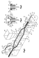
- a web 15 of side connected bags is provided.
- the web 15 is fed from a supply shown schematically at 16 to a bagger section 17.
- the bagger section 17 is separably connected to a bag closure section (not shown).
- the bagger section includes a wheeled support carriage 20.
- the support carriage 20 includes a support frame for supporting bagging mechanisms.
- bagging mechanism is shown in its vertical orientation for gravity loading.
- the machine will be described in such orientation it being recognized that the mechanism may be positioned in a horizontal orientation and at other angular orientations.
- the web 15 is an elongated flattened plastic tube, typically formed of polyethylene film.
- the tube includes a top section 23 for feeding along a mandrel 24, Figure 3.
- the top section 23 is connected to the tops of a chain of side connected bags 25 by front and back lines of weakness in the form of perforations 27, 28.
- Frangible connections 30 connect, adjacent bag side edges, Figures 2 and 3.
- Each bag 25 includes a face 31 and a back 32 interconnected at a bottom 33 by a selected one of a fold or a seal. Side seals adjacent the interconnections 30 delineate the sides of the bags 25.
- the bag faces and backs 31, 32 are respectively connected to the top section 23 by the lines of weakness 27, 28, such that the top section 23 when the web is flattened itself is essentially a tube.
- the web 15 is fed from the supply 16 into a bag feed and preparation portion 35 of the bagger section 17.
- the feed is over the mandrel 24 and past a slitter 36, Figure 3.
- the slitter 36 separates the top section 23 into opposed face and back lips 38, 39.
- the feed through the bag feed and preparation portion 35 is caused by a pair of endless, oppositely rotating, main transport belts 40, 41 supported by oppositely rotating pulley sets 42, 43.
- the main belts 40, 41 are driven by a stepper motor 44, Figure 3 through toothed pulleys 42T, 43T of the sets 42, 43.
- Other of the pulleys 42S, 43S are spring biased by springs S, Figure 1, to tension the belts.
- a plow 45 is provided and shown in Figures 2 and 3. For clarity of illustration the slitter and the plow have been omitted from Figure 1.
- the plow is positioned a short distance upstream from a roller cam 46.
- the lips are drawn along by the main transport belts 40, 41 the lips 38, 39 are respectively folded over the top bag engaging surfaces 40S, 41S of the main transport belts under the action of the plow 45 as depicted in Figure 5.
- the roller cam 46 presses endless, lip transport and clamp belts 48, 49 into complemental grooves 51, 52 in the main transport belts 41, 42 respectively.
- the grooves 51, 52 function as bag clamping surfaces that are complemental with the clamping belts 48, 49. More specifically, the clamp belts are circular in cross section, while the grooves 51, 52 are segments of circles, slightly more than 180° in extent.
- the camming of the clamp belts into the grooves traps the lips 38, 39 between the clamp belts and the grooves.
- the lips due to their coaction with the belts, are capable of resisting substantial stuffing forces as products are forced into the bags at a load station 60. Sections of the clamp belts which are not in the grooves 51, 52 are trained around a set of lip transport belt pulleys 50.
- a bag side separator mechanism 53 is provided at a bag connection breaking station.
- the separator mechanism 53 includes an endless belt 54 which is trained around a pair of spaced pulleys 55 to provide spans which, as shown in Figures 2 and 3, are vertical.
- the pulleys 55 are driven by a motor 57, Figure 2.
- breaking pins 58 projecting from the belt 54 pass between adjacent sides of bags to break the frangible interconnections 30.
- the load station 60 includes a pair of parallel, mirror image, belt spreaders 61, 62.
- the belt spreaders respectively include channels 63, 64.
- the channels 63, 64 respectively guide the main transport belts 40,41, on either side of the load station 60.
- the transport belts 40,41 are in the channels 63, 64, as is clearly seen in Figures 3 and 6, the bags 25 are stretched between the belts in a rectangular top opening configuration.
- FIG. 3 A schematic showing of a supply funnel 66 is included in Figure 3. As suggested by that figure, the products to be packaged are deposited through the rectangular bag openings each time a bag is registered with the supply funnel at the load station.
- a space adjusting mechanism is provided.
- This mechanism includes a spaced pair of adjustment screws 68, 69, Figure 1.
- the adjustment screw 68, 69 are respectively centrally journaled by bearings 70, 71.
- the screws have oppositely threaded sections on either side of their bearings 70, 71 which threadably engage the belt spreaders 61, 62.
- Rotation of a crank 72 causes rotation of the adjustment screw 69.
- the screw 69 is connected to the screw 68 via belts or chains 73, which function to transmit rotation forces so that when the crank 72 is operated the screws 68, 69 are moved equally to drive the spreaders equally into an adjusted spacial, but still parallel, relationship.
- the spring biased pulleys 42S, 43S maintain tension on the main transport belts 40, 41 while permitting relative movement of spans of the belts passing through the spreader channels 63, 64.
- spring biased lip transport belt pulleys 50S maintain tension on the clamp belts 48, 49.
- the spring biased pulleys of both sets are the pulleys to the right as seen in Figure 1, i.e. the entrance end pulleys in the bag feed and preparation portion 35.
- the main transport pulley sets 42, 43 include two idler pulleys 75, 76 downstream from the load station 60.
- the idler pulleys 75, 76 are relatively closely spaced to return the main transport belts 40, 41 into substantially juxtaposed relationship following exit from the load station 60.
- main and lip transport belts are relatively flexed in a vertical plane as they are brought together to grip a bag and relatively flexed in a horizontal plane as they pass through the load station, it will be seen that the belts are flexible in two directions which are orthoganal to one another.
- a conventional support conveyor 160 may be provided, see Figure 2. More frequently a conveyor will be provided under the closure section as disclosed in the New Patent. In either event, suitable height adjustment and locking mechanisms 164 are provided to locate the conveyor 160 in an appropriate position to support the weight of loaded bags being processed into packages.
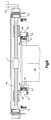
- mirror image main transport belts 100,102 are provided. Since the two are mirror images of one another, the transport belt 100 and the elements which coact with it will be described, it being recognized that corresponding mirror image coaction is provided with the belt 102.
- three lip clamping belts 104-106 are provided.
- a section of plastic film 108 passes upwardly in engagement with a transport path side 110 of the main transport belt 100. The section 108 then passes across a top section 112 of the transport belt 100 and into a recess 114.
- the lip clamping belts 104-106 are disposed in the recess 114 which is in the shape of an arrowhead in cross section to accommodate the three belts.
- the film 108 is reeved over an inside surface of the clamping belt 106 and thence under the transport belts 104,105. If downward force is applied to the film 108, the film tends to push the clamping belt 106 into a corner 115 of the recess 114.
- the belts 104,105 are pulled together with the belt 105 clamping the film against the belt 106 to increase the gripping power of the arrangement as force is applied to the film 108.
- the belt 118 includes a generally triangular upper recess 122.
- the film section 108 extends upwardly along a side 124 of the belt 108, thence over a top surface 125 and into the recess 122.
- the film rides over a relatively small diameter clamping belt 126 and thence is reeved almost completely around a relatively large clamp belt 128.
- the transport belt 118 rides under a rail 130 which retains the clamp belts 126,128 and the film in the recess 122.
- Figure 9 is similar to Figure 8, except that the recess is generally rectangular and the clamp belts are of equal size. Accordingly, like reference numerals with primes added are used in that embodiment.
- main transport belts 132,134 are provided. These belts are very similar to the preferred belts as shown in particular in Figures 5 and 6 with the exception that the clamp belt 49 resides in a recess 135 that is formed in a chamfered outwardly oriented surface 136, rather than a top surface as is the case with the surfaces 40S,41S.
- main transport belts 138,140 are provided.
- the transport belt 138 has an outwardly oriented recess 142 in which upper and lower clamp belts 144,145 are disposed.
- the film section 108 is trained upwardly along the inwardly facing side of the belt 138 over its top and thence downwardly and into the recess 142.
- the film is reeved substantially completely around the lower belt 145, such that when tension force is applied to the film 108 the belt 145 is pulled upwardly to increase the clamping force between the clamping belts 144,145.
- stationary rails 148,150 are provided.
- the rail 148 has in inwardly oriented rectangular recess 152.
- a pair of equally sized circular clamping belts 154,155 are disposed within the recess 152.
- the film section 108 is reeved substantially completely around the upper one of the clamping belts 154 and over the lower clamping belt 155, such that downward force on the film 108 will increase friction around a majority of the perimeter of the upper belt 154 and tightly clamp the film between the clamping belts 154,155.
- Another fixed rail 156 coacts with the belts 154,155 to maintain them in the recess 152.
- Figure 13 differs from the preferred embodiment of Figures 4 and 5 only in that the external surfaces of the transport belts are circular and thus the belts are identified by their reference numerals 40',41'.
- Figure 14 is a variant of the embodiment of Figure 12, in which the lower clamping belt 155 has been omitted and stationary rails are identified by the reference numerals 148',150'.
- the top section 23 of the web 15 is fed along the mandrel 24 and slit by the slitter 36. This forms the lips 38, 39 which are folded over the main transport belts 40, 41 by the action of the plow 45.
- the lip clamp belts 48, 49 descend from the elevated and spring biased pulleys 50S, as shown in Figure 3.
- the roller cam 46 cams the clamp belts 48, 49 respectively into the transport belt recesses 51, 52 to provide very positive and firm support for the bags as they are further processed.
- the motor 55 is operated to drive the belt 54 and cause the breaker pins 58 to rupture the side connections 30.
- the belts are spread under the action of the belt spreaders 61, 62.
- the lips 38, 39 cause the front and back faces 31, 32 adjacent the lead edge of each bag to separate from the lips 38, 39 by tearing a sufficient length of the perforations between them to allow the lead edge to become the mid point in a bag span between the belts as the bag passes longitudinally through the load station 60.
- the perforations adjacent the trailing edge are torn as the trailing part of the bag is spread until the bag achieves a full rectangular opening as shown in Figure 3 in particular.
- the adjacent runs of the main transport belts are brought back together and the loaded bag tops are spread longitudinally of the path of travel either by the planetary stretcher 90 or by opposed air streams from nozzles as taught in the New Patent.
- exit ones 50E of the lip belt pulley set are spaced from the main transport belt and rotatable about angular axes. Expressed more accurately, when the machine is in a vertical loading orientation, the pulleys 50E are above the main transport belt such that the lip transport belts are pulled from the grooves 51, 52.
Abstract

Description
Claims (34)
- A method of performing a work operation utilizing plastic film comprising:a) reeving a section of plastic film at least partially around a conveyor belt;b) trapping the film section between the belt and an elongate coacting mechanism to thereby establish a relative movement resisting grip of the film section between the belt and the mechanism;c) moving at least the belt and the film section along a path of travel;d) performing a work operation on the film and thereby applying a force on the film tending to pull the section away from the belt and mechanism; and,e) allowing the film applied force to increase the relative movement resistance of the grip whereby as such force applied to the film increases there is a proportional increase in grip resistance to slippage of the section relative to and transversely of the belt.
- The method of Claim 1 wherein the belt and section are moved relative to the mechanism.
- The method of Claim 1 wherein the mechanism is a coacting conveyor belt.
- The method of any of Claims 1 through 3, wherein there are two belts, two coacting mechanisms and two film sections.
- The method of Claim 4 wherein each of the mechanism includes a recess and wherein the force application step causes the film sections to be gripped in the recess of the associated first belt.
- The method of any of the preceding claims, wherein resistance to the film applied force to inhibit slippage of the section relative to and transversely of the belt is provided through coaction of the film, the belt and the mechanism alone.
- The method of any of the preceding claims, wherein there are first and second film sections, the belts are first conveyor belts and there are two mechanisms in the form of a pair of second belts, the method further comprising:a) bringing the first and second film sections respectively into engagement with a side part of a surface of an associated one of a spaced pair of the first conveyor belts;b) folding the sections over the respective first belts to bring another part of each section into engagement with another part of its associated first belt;c) positioning a still further part of each section between its associated first belt and an associated one of the pair of second belts to produce frictional gripping of the sections due to coaction of the belts and sections; and,d) applying a force to at least one of the sections to pull the one section against the associated belts and resisting such force with a gripping resistance produced by coaction of the one section and its associated belts alone.
- The method of Claim 7 wherein each of the first belts includes a recess and wherein the force application step causes the still further part of said one section to be gripped in the recess of the associated first belt.
- The method of Claim 7 or Claim 8, wherein the side parts are side surfaces facing one another on opposite sides of a path of travel and wherein the another parts are top surfaces.
- The method of Claim 9 wherein the another parts each include a recess and the positioning step includes camming the belts of the second pair respectively into the recesses.
- The method of any of Claims 7 through 10, wherein the side parts are side surfaces wherein the another parts are side surfaces opposite the side parts of their respective belts.
- The method of Claim 11 wherein the another parts include a recess and the positioning step includes camming the belts of the second pair respectively into the recesses.
- The method of any of the preceding claims, wherein there are two film sections which are bag lips further including spreading the lips to open the bag and loading the bag to make a package.
- A method of supporting and transporting plastic film for a work operation comprising:a) extending each of a pair of film sections to project in a direction away from a film path of travel;b) bringing each of the film sections into engagement with a segment of a surface of each belt of an associated one of two spaced sets of coacting transport belts; and,c) establishing at least a partial wrap around self gripping longitudinally continuous relationship between each section and at least one belt of the associated set such that a coacting section gripping relationship is established between each section and its associated belt set whereby substantially to prevent movement of each section transverse to a path of belt movement, the prevented movement being in a direction toward a work operation applying forces to the film.
- The method of Claim 14 wherein the work operation is a film stretching operation.
- The method of Claim 14 wherein the sections are bag lips and the work operation is bag loading.
- A method of supporting a bag in an open condition for filling an interior volume of the bag, the method comprising:a) bringing first parts of front and back lips of a bag respectively into engagement with a side part of a surface of an associated one of a spaced pair of first conveyor belts;b) folding the lips over the respective first belts to bring another part of each lip into engagement with another part of its associated first belt, the another parts being spaced further from the bag volume than the first parts;c) reeving a still further part of each lip around an associated one of a second pair of belts, the still further parts being respectively spaced further from the volume than said another parts of their respective lips;d) applying a loading force to the bag to pull the lips against the respective belts and thereby pull the second belts toward the first belts and grip the still further parts between their respective associated belts and resist such loading force with a gripping resistance that increases as the loading force increases.
- The method of Claim 17 wherein each of the first belts includes a recess and wherein the loading force application step causes the still further parts to be gripped in the recess.
- The method of Claim 17 or Claim 18, wherein when the bag is suspended vertically, the side parts are generally vertical surfaces facing one another on opposite sides of a path of bag travel and wherein the another parts are top surfaces.
- The method of Claim 19 wherein the another parts each include a recess and the reeving step includes camming the belts of the second pair respectively into the recesses.
- A process of manipulating a chain of side connected bags in preparation for loading and closure to form packages, the process comprising:a) successively gripping the bags between a pair of main transport belts with upstanding front and back lips of the bags projecting in one direction from the belts and bodies of the bags projecting from the belts in an opposite direction;b) oppositely folding the lips over the main belts; andc) securing the lips to the main belts by camming portions of each of the folded over lips into an elongate recess in the belt over which it is folded by forcing each of a pair of clamping belts into an associated recess and by the securement of the lips to the belts resisting bag loading forces applied to such bags transversely of the path.
- The process of Claim 21 wherein each of the main belt recesses and the associated clamping belt have complemental cross-sectional configurations.
- The process of Claim 22 wherein the configurations are at least partially circular.
- The process of any of Claims 21 through 23, further including the step of spreading the main belts apart after the lips have been so secured to form rectangular load openings in the bags.
- The process of Claim 24 further including separating sections of the lips from bag faces and backs adjacent sides of the bags as the rectangular openings are formed.
- In a machine for transporting a plastic film for a work operation an improved film gripping system comprising:a) a first endless conveyor belt having an endless film engaging surface;b) the first belt also having an endless film engaging recess adjacent the surface;c) a coacting, second endless belt the second belt also having an endless bag engaging surface, the belts being flexible in orthogonal directions; andd) the recess and the second belt having complemental cross sectional configurations such that film gripping and supporting relationship is established when the second belt is in the recess with a section of film trapped between the second belt and surfaces defining the recess.
- The machine of Claim 26 wherein at least one of the belts is circular in cross section.
- The machine of Claim 26 or Claim 27 further comprising:a) first and second pairs of conveyor belts positioned on opposite sides of a film transport path of travel;b) one belt of each pair including an elongate recess;c) film diverter means for diverting film sections moving along the path respectively into engagement with the one belts; and,d) belt camming means positioned along the path downstream from the diverter means for forcing the other belt of each pair into the recess of its paired said one belt and thereby trap said film sections respectively between belts of the pairs.
- The machine of Claim 28 wherein each of the recesses is in a belt surface generally transverse to the path.
- The machine of Claim 28 wherein each of the recesses is in a belt surface generally parallel to the path.
- The machine of any of Claims 26 through 30, wherein the machine is a packaging machine for opening and loading bags sequentially to form packages having an improved bag transport system comprising:a) first and second pairs of conveyor belts positioned on opposite sides of a bag path of travel to and through a loading station;b) one belt of each pair including an elongate recess;c) bag lip diverter means for oppositely diverting lips of bags moving along the path respectively into engagement with the one belts; and,d) belt camming means positioned along the path downstream from the diverter means for forcing the other belt of each pair into the recess of its paired said one belt and thereby trap bag lips respectively between belts of the pairs.
- The machine of any of Claims 26 through 31, wherein the belt recess is a segment of a circle in cross section, the segment having an extent greater than 180°.
- A method of supporting and opening bags of a chain of side interconnected bags comprising:a) extending each of a pair of bag lips to project from a load opening of the bag in a direction away from a bag delineated product receiving space;b) bringing each of the bag lips into longitudinally continuous engagement with a segment of a surface of each belt of an associated one of two spaced sets of coacting transport belts; and,c) establishing at least a partial wrap around relationship between each lip and at least one belt of the associated set such that a coacting lip gripping relationship is established between each lip and its associated belt set whereby substantially to prevent movement when bag loading forces are applied of each lip transverse to a path of belt movement, the prevented movement being in a direction toward said product space.
- The process of Claim 33 wherein steps (a) through (c) are repeated with each successive bag in the chain.
Applications Claiming Priority (2)
| Application Number | Priority Date | Filing Date | Title |
|---|---|---|---|
| US08/699,128 US5722218A (en) | 1996-08-16 | 1996-08-16 | Plastic transport system |
| US699128 | 1996-08-16 |
Publications (2)
| Publication Number | Publication Date |
|---|---|
| EP0825116A1 true EP0825116A1 (en) | 1998-02-25 |
| EP0825116B1 EP0825116B1 (en) | 1999-11-03 |
Family
ID=24808064
Family Applications (1)
| Application Number | Title | Priority Date | Filing Date |
|---|---|---|---|
| EP97306188A Expired - Lifetime EP0825116B1 (en) | 1996-08-16 | 1997-08-14 | Method and apparatus for transporting and opening bags of a web of interconnected bags |
Country Status (11)
| Country | Link |
|---|---|
| US (1) | US5722218A (en) |
| EP (1) | EP0825116B1 (en) |
| AR (1) | AR007746A1 (en) |
| AT (1) | ATE186263T1 (en) |
| BR (1) | BR9704371A (en) |
| CA (1) | CA2213190C (en) |
| DE (1) | DE69700734T2 (en) |
| DK (1) | DK0825116T3 (en) |
| ES (1) | ES2138433T3 (en) |
| GR (1) | GR3032435T3 (en) |
| MX (1) | MX9706163A (en) |
Cited By (5)
| Publication number | Priority date | Publication date | Assignee | Title |
|---|---|---|---|---|
| WO1999057017A1 (en) * | 1998-04-21 | 1999-11-11 | Schur Packaging Systems A/S | A method and a system for filling goods in bags from a coherent series of bag members |
| EP1002719A1 (en) * | 1998-11-20 | 2000-05-24 | Automated Packaging Systems, Inc. | Process for making interconnected bags |
| US6990787B2 (en) | 2001-10-08 | 2006-01-31 | Schur Packaging Systems A/S | Method and apparatus for packing of items |
| CN106458372A (en) * | 2014-06-30 | 2017-02-22 | 舒尔技术股份公司 | Method and apparatus for packing items, liquid or loose material in film bags, and a bag web |
| US10807778B2 (en) | 2014-06-30 | 2020-10-20 | Schur Technology A/S | Bag web and method for packing a product in film bags by using such a bag web |
Families Citing this family (30)
| Publication number | Priority date | Publication date | Assignee | Title |
|---|---|---|---|---|
| ES2137758T3 (en) * | 1996-08-16 | 1999-12-16 | Automated Packaging Syst Inc | MACHINE AND SEALING PROCEDURE. |
| US5743070A (en) * | 1996-08-16 | 1998-04-28 | Automated Packaging Systems, Inc. | Packaging machine, material and method |
| SE509523C2 (en) * | 1997-06-05 | 1999-02-08 | Joker System Ab | Device and method for converting a longitudinal thickening hose into a web of arranged packing blanks and a hose intended for the device and the method |
| CA2324752C (en) | 1999-10-27 | 2008-12-30 | Gates Automation, Inc. | Bag filling and sealing machine and method for handling bags |
| US6367975B1 (en) | 2001-05-24 | 2002-04-09 | Automated Packaging Systems, Inc. | Packaging web and process |
| US6742321B2 (en) | 2002-09-30 | 2004-06-01 | Gates Automation, Inc. | Flange alignment and grasping assembly for bag handling apparatus |
| US20050132672A1 (en) * | 2003-12-17 | 2005-06-23 | Hershey Lerner | Packaging machine and process |
| EP3150369B1 (en) | 2004-06-01 | 2020-03-18 | Automated Packaging Systems, Inc. | Web for making fluid filled units |
| US7897219B2 (en) | 2004-06-01 | 2011-03-01 | Automated Packaging Systems, Inc. | Web and method for making fluid filled units |
| US8549822B2 (en) * | 2006-07-17 | 2013-10-08 | Automated Packaging Systems, Inc. | Packaging machine and process |
| AU2007334053B2 (en) * | 2006-12-15 | 2011-04-21 | Ccl Label Gmbh | Stretch film sleeve label applicator |
| EP2209614B1 (en) | 2007-10-31 | 2015-08-19 | Automated Packaging Systems, Inc. | Web and method for making fluid filled units |
| US9205622B2 (en) | 2009-02-27 | 2015-12-08 | Automated Packaging Systems, Inc. | Web and method for making fluid filled units |
| US9623622B2 (en) | 2010-02-24 | 2017-04-18 | Michael Baines | Packaging materials and methods |
| SE535040C2 (en) * | 2010-04-22 | 2012-03-20 | Pronova Ab | Method and apparatus for manufacturing a continuous bag-shaped package blank |
| MX337068B (en) * | 2011-02-21 | 2016-02-11 | Automated Packaging Syst Inc | Packaging machine and process. |
| SE535972C2 (en) * | 2011-06-22 | 2013-03-12 | Pronova Ab | Apparatus and method of packing goods in an inflatable bag |
| MX341459B (en) | 2011-07-07 | 2016-08-19 | Automated Packaging Systems Inc | Air cushion inflation machine. |
| CA2900643A1 (en) | 2013-03-15 | 2014-09-18 | Automated Packaging Systems, Inc. | On-demand inflatable packaging |
| EP2810878B1 (en) * | 2013-06-04 | 2016-11-02 | Cama1 S.p.A. | Machine and method for secondary packaging of articles |
| CH708587A1 (en) * | 2013-09-16 | 2015-03-31 | M Tanner Ag | Wedge conveyor with at least one clamping unit. |
| US9844911B2 (en) | 2013-11-21 | 2017-12-19 | Automated Packaging Systems, Inc. | Air cushion inflation machine |
| SG10201909092SA (en) | 2015-03-31 | 2019-11-28 | Fisher & Paykel Healthcare Ltd | A user interface and system for supplying gases to an airway |
| CN114569856A (en) | 2016-08-11 | 2022-06-03 | 费雪派克医疗保健有限公司 | Collapsible catheter, patient interface and headgear connector |
| CN107416272B (en) * | 2017-03-03 | 2023-03-28 | 广东省智能制造研究所 | Opening mechanism for bag opening of packaging bag |
| DK179277B1 (en) * | 2017-03-27 | 2018-03-26 | Schur Tech As | Bag run and method and apparatus for packing items |
| CN116438057A (en) | 2020-10-08 | 2023-07-14 | 希悦尔公司 | Buffering type web material capable of closing bag |
| IT202100002633A1 (en) * | 2021-02-05 | 2022-08-05 | Ica Spa | CLOSURE SYSTEM FOR PACKAGES WITH SNAP-IN RESEALABLE ELEMENT |
| WO2022182691A1 (en) | 2021-02-26 | 2022-09-01 | Automated Packaging Systems, Llc | Webs of preformed bags with expandable sheet cushioning |
| CN113479586A (en) * | 2021-07-21 | 2021-10-08 | 东莞市冠佳电子设备有限公司 | Double-station high-precision efficient carrying device |
Citations (3)
| Publication number | Priority date | Publication date | Assignee | Title |
|---|---|---|---|---|
| US3699746A (en) * | 1971-04-09 | 1972-10-24 | Basic Packaging Systems Inc | Apparatus for filling a chain of connected bag elements |
| FR2145774A5 (en) * | 1971-07-09 | 1973-02-23 | Hercules Membrino | Filling and sealing plastics bags with easy separation of the finishe |
| WO1994025345A1 (en) * | 1993-05-05 | 1994-11-10 | Jan Jostler | Method and an apparatus for forming and filling packages |
Family Cites Families (38)
| Publication number | Priority date | Publication date | Assignee | Title |
|---|---|---|---|---|
| US2671587A (en) * | 1948-07-30 | 1954-03-09 | Clarence W Vogt | Bag filling machine |
| US2667997A (en) * | 1948-10-07 | 1954-02-02 | Clarence W Vogt | Paired bag filling machine |
| US2845166A (en) * | 1950-10-16 | 1958-07-29 | Schaeffer Werner | Belt conveyor |
| US3019855A (en) * | 1958-04-09 | 1962-02-06 | Cambridge Filter Mfg Corp | Filters |
| US3120892A (en) * | 1959-12-04 | 1964-02-11 | Arenco Ab | Conveyor |
| CH404514A (en) * | 1960-04-13 | 1965-12-15 | Meulen Leonard V D | Method and device for processing a strip of flexible sheet-like material and strips of material processed according to this method |
| US3197936A (en) * | 1961-10-06 | 1965-08-03 | Edwin E Messmer | Method and apparatus for conditioning bags for loading |
| NL281183A (en) * | 1962-07-19 | |||
| US3323703A (en) * | 1963-12-31 | 1967-06-06 | Kalle Ag | Conveyors for webs of material |
| DE1225537B (en) * | 1964-10-30 | 1966-09-22 | Dohmeier & Strothotte K G | Process and device for the continuous production of bags filled with large pieces of bulk goods |
| US3427684A (en) * | 1967-01-26 | 1969-02-18 | Exxon Research Engineering Co | Biaxial stretching machine |
| US3559874A (en) * | 1968-05-08 | 1971-02-02 | Dow Chemical Co | Series bag construction |
| US3540183A (en) * | 1968-07-08 | 1970-11-17 | William A Bodolay | Machine for making two compartment unitary bag |
| US3567095A (en) * | 1968-12-19 | 1971-03-02 | Joseph C Geist | Belt structure |
| US3583127A (en) * | 1969-04-16 | 1971-06-08 | Dow Chemical Co | Arrangement for controllably feeding connected bag elements to filling or like apparatus |
| DE1928661A1 (en) * | 1969-06-06 | 1971-01-14 | Dohmeier & Strothotte Kg | Packing arrangement |
| US3610501A (en) * | 1970-03-18 | 1971-10-05 | Young William E | Film-transporting apparatus |
| US3817017A (en) * | 1970-10-13 | 1974-06-18 | O Titchenal | Bag construction and method for filling the same |
| US3773235A (en) * | 1970-10-26 | 1973-11-20 | American Can Co | Packaging apparatus |
| US3744211A (en) * | 1971-04-09 | 1973-07-10 | Dow Chemical Co | Automatic bag filling method |
| US3746056A (en) * | 1971-06-07 | 1973-07-17 | Dow Chemical Co | Collapsible filling spout |
| US3791573A (en) * | 1971-11-15 | 1974-02-12 | Basic Packaging Sys Inc | Bag construction |
| US3779449A (en) * | 1972-05-05 | 1973-12-18 | H Membrino | Linear strip of severable bags |
| US3969746A (en) * | 1973-12-10 | 1976-07-13 | Texas Instruments Incorporated | Vertical multijunction solar cell |
| NL7614290A (en) * | 1976-12-22 | 1978-06-26 | Lockwood International Bv | DEVICE FOR SPREADING A DOUBLE STRAP PACKING MATERIAL. |
| US4201031A (en) * | 1978-09-27 | 1980-05-06 | Rexham Corporation | Method of making, opening, filling and sealing a two-compartment pouch |
| US4558556A (en) * | 1980-06-30 | 1985-12-17 | Joker System Aktiebolag | Belt having a succession of packaging blanks and method for filling the blanks |
| JPS57194918A (en) * | 1981-05-23 | 1982-11-30 | Taisei Kikai Kk | Packer |
| FR2519944B1 (en) * | 1982-01-19 | 1986-08-14 | Gimar Sa | BELT TELETRANSPORTER |
| US4586319A (en) * | 1982-09-30 | 1986-05-06 | Minigrip, Inc. | Method of and means for easy opening bags |
| US4654878A (en) * | 1982-09-30 | 1987-03-31 | Signode Corporation | Plastic bag chain |
| US4514962A (en) * | 1982-12-16 | 1985-05-07 | Minigrip, Inc. | Method and apparatus for filling reclosable bags |
| US4665552A (en) * | 1985-06-18 | 1987-05-12 | Minigrip, Inc. | Zipper equipped bags and method of and means for manually filling and separating them |
| US4850178A (en) * | 1988-07-01 | 1989-07-25 | Minigrip, Inc. | Device for opening a double link bag chain |
| US4969310A (en) * | 1989-05-12 | 1990-11-13 | Automated Packaging Systems, Inc. | Packaging machine and method |
| US4945714A (en) * | 1989-11-14 | 1990-08-07 | Package Machinery Company, Bodolay/Pratt Division | Form, fill, seal and separate packaging machine for reclosable containers |
| US5187917A (en) * | 1990-10-29 | 1993-02-23 | Cvp Systems, Inc. | Automatic packaging apparatus and method and flexible pouch therefor |
| US5197318A (en) * | 1992-01-27 | 1993-03-30 | Exaire Co. | Metal forming method and apparatus |
-
1996
- 1996-08-16 US US08/699,128 patent/US5722218A/en not_active Expired - Lifetime
-
1997
- 1997-08-12 MX MX9706163A patent/MX9706163A/en unknown
- 1997-08-14 AT AT97306188T patent/ATE186263T1/en not_active IP Right Cessation
- 1997-08-14 ES ES97306188T patent/ES2138433T3/en not_active Expired - Lifetime
- 1997-08-14 DE DE69700734T patent/DE69700734T2/en not_active Expired - Lifetime
- 1997-08-14 EP EP97306188A patent/EP0825116B1/en not_active Expired - Lifetime
- 1997-08-14 DK DK97306188T patent/DK0825116T3/en active
- 1997-08-15 AR ARP970103737A patent/AR007746A1/en unknown
- 1997-08-15 BR BR9704371A patent/BR9704371A/en not_active IP Right Cessation
- 1997-08-15 CA CA002213190A patent/CA2213190C/en not_active Expired - Lifetime
-
2000
- 2000-01-19 GR GR20000400132T patent/GR3032435T3/en not_active IP Right Cessation
Patent Citations (3)
| Publication number | Priority date | Publication date | Assignee | Title |
|---|---|---|---|---|
| US3699746A (en) * | 1971-04-09 | 1972-10-24 | Basic Packaging Systems Inc | Apparatus for filling a chain of connected bag elements |
| FR2145774A5 (en) * | 1971-07-09 | 1973-02-23 | Hercules Membrino | Filling and sealing plastics bags with easy separation of the finishe |
| WO1994025345A1 (en) * | 1993-05-05 | 1994-11-10 | Jan Jostler | Method and an apparatus for forming and filling packages |
Cited By (10)
| Publication number | Priority date | Publication date | Assignee | Title |
|---|---|---|---|---|
| WO1999057017A1 (en) * | 1998-04-21 | 1999-11-11 | Schur Packaging Systems A/S | A method and a system for filling goods in bags from a coherent series of bag members |
| AU753412B2 (en) * | 1998-04-21 | 2002-10-17 | Schur Packaging Systems A/S | A method and a system for filling goods in bags from a coherent series of bag members |
| US6591586B1 (en) | 1998-04-21 | 2003-07-15 | Schur Packaging Systems A/S | Method and a system for filling goods in bags from a coherent series of bag members |
| US7048441B2 (en) | 1998-04-21 | 2006-05-23 | Schur Packaging Systems A/S | Method and system for filling goods in bags from a coherent series of bag members |
| CZ302751B6 (en) * | 1998-04-21 | 2011-10-19 | Schur Packaging Systems A/S | Method for packaging items or loose materials in foil bags, apparatus for making the same and packaging web for use with the method |
| EP1002719A1 (en) * | 1998-11-20 | 2000-05-24 | Automated Packaging Systems, Inc. | Process for making interconnected bags |
| US6990787B2 (en) | 2001-10-08 | 2006-01-31 | Schur Packaging Systems A/S | Method and apparatus for packing of items |
| CN106458372A (en) * | 2014-06-30 | 2017-02-22 | 舒尔技术股份公司 | Method and apparatus for packing items, liquid or loose material in film bags, and a bag web |
| CN106458372B (en) * | 2014-06-30 | 2019-06-04 | 舒尔技术股份公司 | Method and apparatus and landing net for being packaged in article, liquid or discrete material in film bag |
| US10807778B2 (en) | 2014-06-30 | 2020-10-20 | Schur Technology A/S | Bag web and method for packing a product in film bags by using such a bag web |
Also Published As
| Publication number | Publication date |
|---|---|
| ES2138433T3 (en) | 2000-01-01 |
| MX9706163A (en) | 1998-02-28 |
| AR007746A1 (en) | 1999-11-10 |
| DE69700734D1 (en) | 1999-12-09 |
| DK0825116T3 (en) | 2000-05-08 |
| US5722218A (en) | 1998-03-03 |
| DE69700734T2 (en) | 2000-06-08 |
| CA2213190A1 (en) | 1998-02-16 |
| EP0825116B1 (en) | 1999-11-03 |
| BR9704371A (en) | 1999-03-16 |
| ATE186263T1 (en) | 1999-11-15 |
| CA2213190C (en) | 2001-12-04 |
| GR3032435T3 (en) | 2000-05-31 |
Similar Documents
| Publication | Publication Date | Title |
|---|---|---|
| EP0825116B1 (en) | Method and apparatus for transporting and opening bags of a web of interconnected bags | |
| EP2678230B1 (en) | Conveyor system and method | |
| MXPA97006163A (en) | Plast conveyor system | |
| EP1008523B1 (en) | Packaging process for a web of interconnected bags | |
| US8549822B2 (en) | Packaging machine and process | |
| EP1260443B1 (en) | Packaging web and process of packaging utilizing such web | |
| CA1318297C (en) | Packaging machine & method | |
| US5996319A (en) | Packaging machine, material and method | |
| US5887412A (en) | Packaging machine, material and method | |
| US6035611A (en) | Process for making packaging materials | |
| RU2293046C2 (en) | Method of and device for packing of articles | |
| US4702471A (en) | Article transport arrangement | |
| CA2263052C (en) | Packaging machine, material and method | |
| JPH0977223A (en) | Long article carrying equipment | |
| JP2017128429A (en) | Split device of sheet body | |
| NL9300420A (en) | Device for packaging bread in bags |
Legal Events
| Date | Code | Title | Description |
|---|---|---|---|
| PUAI | Public reference made under article 153(3) epc to a published international application that has entered the european phase |
Free format text: ORIGINAL CODE: 0009012 |
|
| AK | Designated contracting states |
Kind code of ref document: A1 Designated state(s): AT BE CH DE DK ES FI FR GB GR IE IT LI LU MC NL PT SE |
|
| AX | Request for extension of the european patent |
Free format text: AL;LT;LV;RO;SI |
|
| 17P | Request for examination filed |
Effective date: 19980801 |
|
| AKX | Designation fees paid |
Free format text: AT BE CH DE DK ES FI FR GB GR IE IT LI LU MC NL PT SE |
|
| RBV | Designated contracting states (corrected) |
Designated state(s): AT BE CH DE DK ES FI FR GB GR IE IT LI LU MC NL PT SE |
|
| 17Q | First examination report despatched |
Effective date: 19981007 |
|
| GRAG | Despatch of communication of intention to grant |
Free format text: ORIGINAL CODE: EPIDOS AGRA |
|
| GRAG | Despatch of communication of intention to grant |
Free format text: ORIGINAL CODE: EPIDOS AGRA |
|
| GRAG | Despatch of communication of intention to grant |
Free format text: ORIGINAL CODE: EPIDOS AGRA |
|
| GRAH | Despatch of communication of intention to grant a patent |
Free format text: ORIGINAL CODE: EPIDOS IGRA |
|
| GRAH | Despatch of communication of intention to grant a patent |
Free format text: ORIGINAL CODE: EPIDOS IGRA |
|
| GRAA | (expected) grant |
Free format text: ORIGINAL CODE: 0009210 |
|
| AK | Designated contracting states |
Kind code of ref document: B1 Designated state(s): AT BE CH DE DK ES FI FR GB GR IE IT LI LU MC NL PT SE |
|
| REF | Corresponds to: |
Ref document number: 186263 Country of ref document: AT Date of ref document: 19991115 Kind code of ref document: T |
|
| REG | Reference to a national code |
Ref country code: CH Ref legal event code: EP |
|
| REG | Reference to a national code |
Ref country code: CH Ref legal event code: NV Representative=s name: RITSCHER & SEIFERT |
|
| REF | Corresponds to: |
Ref document number: 69700734 Country of ref document: DE Date of ref document: 19991209 |
|
| ET | Fr: translation filed | ||
| ITF | It: translation for a ep patent filed |
Owner name: CALVANI SALVI E VERONELLI S.R.L. |
|
| REG | Reference to a national code |
Ref country code: ES Ref legal event code: FG2A Ref document number: 2138433 Country of ref document: ES Kind code of ref document: T3 |
|
| REG | Reference to a national code |
Ref country code: IE Ref legal event code: FG4D |
|
| PG25 | Lapsed in a contracting state [announced via postgrant information from national office to epo] |
Ref country code: PT Free format text: LAPSE BECAUSE OF FAILURE TO SUBMIT A TRANSLATION OF THE DESCRIPTION OR TO PAY THE FEE WITHIN THE PRESCRIBED TIME-LIMIT Effective date: 20000203 |
|
| REG | Reference to a national code |
Ref country code: DK Ref legal event code: T3 |
|
| PG25 | Lapsed in a contracting state [announced via postgrant information from national office to epo] |
Ref country code: LU Free format text: LAPSE BECAUSE OF NON-PAYMENT OF DUE FEES Effective date: 20000814 |
|
| PG25 | Lapsed in a contracting state [announced via postgrant information from national office to epo] |
Ref country code: MC Free format text: THE PATENT HAS BEEN ANNULLED BY A DECISION OF A NATIONAL AUTHORITY Effective date: 20000831 |
|
| PLBE | No opposition filed within time limit |
Free format text: ORIGINAL CODE: 0009261 |
|
| STAA | Information on the status of an ep patent application or granted ep patent |
Free format text: STATUS: NO OPPOSITION FILED WITHIN TIME LIMIT |
|
| 26N | No opposition filed | ||
| PGFP | Annual fee paid to national office [announced via postgrant information from national office to epo] |
Ref country code: GR Payment date: 20010731 Year of fee payment: 5 |
|
| REG | Reference to a national code |
Ref country code: GB Ref legal event code: IF02 |
|
| PG25 | Lapsed in a contracting state [announced via postgrant information from national office to epo] |
Ref country code: GR Free format text: LAPSE BECAUSE OF NON-PAYMENT OF DUE FEES Effective date: 20030305 |
|
| PGFP | Annual fee paid to national office [announced via postgrant information from national office to epo] |
Ref country code: DK Payment date: 20030715 Year of fee payment: 7 Ref country code: CH Payment date: 20030715 Year of fee payment: 7 |
|
| PGFP | Annual fee paid to national office [announced via postgrant information from national office to epo] |
Ref country code: FI Payment date: 20030717 Year of fee payment: 7 |
|
| PGFP | Annual fee paid to national office [announced via postgrant information from national office to epo] |
Ref country code: NL Payment date: 20030718 Year of fee payment: 7 |
|
| PGFP | Annual fee paid to national office [announced via postgrant information from national office to epo] |
Ref country code: SE Payment date: 20030722 Year of fee payment: 7 |
|
| PGFP | Annual fee paid to national office [announced via postgrant information from national office to epo] |
Ref country code: IE Payment date: 20030730 Year of fee payment: 7 |
|
| PGFP | Annual fee paid to national office [announced via postgrant information from national office to epo] |
Ref country code: BE Payment date: 20030801 Year of fee payment: 7 Ref country code: AT Payment date: 20030801 Year of fee payment: 7 |
|
| PGFP | Annual fee paid to national office [announced via postgrant information from national office to epo] |
Ref country code: ES Payment date: 20030811 Year of fee payment: 7 |
|
| PG25 | Lapsed in a contracting state [announced via postgrant information from national office to epo] |
Ref country code: FI Free format text: LAPSE BECAUSE OF NON-PAYMENT OF DUE FEES Effective date: 20040814 Ref country code: AT Free format text: LAPSE BECAUSE OF NON-PAYMENT OF DUE FEES Effective date: 20040814 |
|
| PG25 | Lapsed in a contracting state [announced via postgrant information from national office to epo] |
Ref country code: SE Free format text: LAPSE BECAUSE OF NON-PAYMENT OF DUE FEES Effective date: 20040815 |
|
| PG25 | Lapsed in a contracting state [announced via postgrant information from national office to epo] |
Ref country code: IE Free format text: LAPSE BECAUSE OF NON-PAYMENT OF DUE FEES Effective date: 20040816 |
|
| PG25 | Lapsed in a contracting state [announced via postgrant information from national office to epo] |
Ref country code: ES Free format text: LAPSE BECAUSE OF NON-PAYMENT OF DUE FEES Effective date: 20040817 |
|
| PG25 | Lapsed in a contracting state [announced via postgrant information from national office to epo] |
Ref country code: LI Free format text: LAPSE BECAUSE OF NON-PAYMENT OF DUE FEES Effective date: 20040831 Ref country code: DK Free format text: LAPSE BECAUSE OF NON-PAYMENT OF DUE FEES Effective date: 20040831 Ref country code: CH Free format text: LAPSE BECAUSE OF NON-PAYMENT OF DUE FEES Effective date: 20040831 Ref country code: BE Free format text: LAPSE BECAUSE OF NON-PAYMENT OF DUE FEES Effective date: 20040831 |
|
| BERE | Be: lapsed |
Owner name: *AUTOMATED PACKAGING SYSTEMS INC. Effective date: 20040831 |
|
| PG25 | Lapsed in a contracting state [announced via postgrant information from national office to epo] |
Ref country code: NL Free format text: LAPSE BECAUSE OF NON-PAYMENT OF DUE FEES Effective date: 20050301 |
|
| EUG | Se: european patent has lapsed | ||
| REG | Reference to a national code |
Ref country code: CH Ref legal event code: PL |
|
| NLV4 | Nl: lapsed or anulled due to non-payment of the annual fee |
Effective date: 20050301 |
|
| REG | Reference to a national code |
Ref country code: IE Ref legal event code: MM4A |
|
| REG | Reference to a national code |
Ref country code: DK Ref legal event code: EBP |
|
| PG25 | Lapsed in a contracting state [announced via postgrant information from national office to epo] |
Ref country code: IT Free format text: LAPSE BECAUSE OF NON-PAYMENT OF DUE FEES;WARNING: LAPSES OF ITALIAN PATENTS WITH EFFECTIVE DATE BEFORE 2007 MAY HAVE OCCURRED AT ANY TIME BEFORE 2007. THE CORRECT EFFECTIVE DATE MAY BE DIFFERENT FROM THE ONE RECORDED. Effective date: 20050814 |
|
| REG | Reference to a national code |
Ref country code: ES Ref legal event code: FD2A Effective date: 20040817 |
|
| BERE | Be: lapsed |
Owner name: *AUTOMATED PACKAGING SYSTEMS INC. Effective date: 20040831 |
|
| REG | Reference to a national code |
Ref country code: FR Ref legal event code: PLFP Year of fee payment: 19 |
|
| REG | Reference to a national code |
Ref country code: FR Ref legal event code: PLFP Year of fee payment: 20 |
|
| PGFP | Annual fee paid to national office [announced via postgrant information from national office to epo] |
Ref country code: GB Payment date: 20160830 Year of fee payment: 20 Ref country code: DE Payment date: 20160826 Year of fee payment: 20 |
|
| PGFP | Annual fee paid to national office [announced via postgrant information from national office to epo] |
Ref country code: FR Payment date: 20160825 Year of fee payment: 20 |
|
| REG | Reference to a national code |
Ref country code: DE Ref legal event code: R071 Ref document number: 69700734 Country of ref document: DE |
|
| REG | Reference to a national code |
Ref country code: GB Ref legal event code: PE20 Expiry date: 20170813 |
|
| PG25 | Lapsed in a contracting state [announced via postgrant information from national office to epo] |
Ref country code: GB Free format text: LAPSE BECAUSE OF EXPIRATION OF PROTECTION Effective date: 20170813 |