EP0825445A2 - Automatic biochemical analyzer - Google Patents
Automatic biochemical analyzer Download PDFInfo
- Publication number
- EP0825445A2 EP0825445A2 EP97306356A EP97306356A EP0825445A2 EP 0825445 A2 EP0825445 A2 EP 0825445A2 EP 97306356 A EP97306356 A EP 97306356A EP 97306356 A EP97306356 A EP 97306356A EP 0825445 A2 EP0825445 A2 EP 0825445A2
- Authority
- EP
- European Patent Office
- Prior art keywords
- reagent
- reaction
- turntable
- sample
- stirring
- Prior art date
- Legal status (The legal status is an assumption and is not a legal conclusion. Google has not performed a legal analysis and makes no representation as to the accuracy of the status listed.)
- Granted
Links
Images


Classifications
-
- G—PHYSICS
- G01—MEASURING; TESTING
- G01N—INVESTIGATING OR ANALYSING MATERIALS BY DETERMINING THEIR CHEMICAL OR PHYSICAL PROPERTIES
- G01N35/00—Automatic analysis not limited to methods or materials provided for in any single one of groups G01N1/00 - G01N33/00; Handling materials therefor
- G01N35/02—Automatic analysis not limited to methods or materials provided for in any single one of groups G01N1/00 - G01N33/00; Handling materials therefor using a plurality of sample containers moved by a conveyor system past one or more treatment or analysis stations
- G01N35/025—Automatic analysis not limited to methods or materials provided for in any single one of groups G01N1/00 - G01N33/00; Handling materials therefor using a plurality of sample containers moved by a conveyor system past one or more treatment or analysis stations having a carousel or turntable for reaction cells or cuvettes
-
- G—PHYSICS
- G01—MEASURING; TESTING
- G01N—INVESTIGATING OR ANALYSING MATERIALS BY DETERMINING THEIR CHEMICAL OR PHYSICAL PROPERTIES
- G01N35/00—Automatic analysis not limited to methods or materials provided for in any single one of groups G01N1/00 - G01N33/00; Handling materials therefor
- G01N2035/00465—Separating and mixing arrangements
- G01N2035/00534—Mixing by a special element, e.g. stirrer
-
- G—PHYSICS
- G01—MEASURING; TESTING
- G01N—INVESTIGATING OR ANALYSING MATERIALS BY DETERMINING THEIR CHEMICAL OR PHYSICAL PROPERTIES
- G01N35/00—Automatic analysis not limited to methods or materials provided for in any single one of groups G01N1/00 - G01N33/00; Handling materials therefor
- G01N35/00584—Control arrangements for automatic analysers
- G01N35/0092—Scheduling
- G01N2035/0094—Scheduling optimisation; experiment design
-
- G—PHYSICS
- G01—MEASURING; TESTING
- G01N—INVESTIGATING OR ANALYSING MATERIALS BY DETERMINING THEIR CHEMICAL OR PHYSICAL PROPERTIES
- G01N35/00—Automatic analysis not limited to methods or materials provided for in any single one of groups G01N1/00 - G01N33/00; Handling materials therefor
- G01N35/02—Automatic analysis not limited to methods or materials provided for in any single one of groups G01N1/00 - G01N33/00; Handling materials therefor using a plurality of sample containers moved by a conveyor system past one or more treatment or analysis stations
- G01N35/04—Details of the conveyor system
- G01N2035/0439—Rotary sample carriers, i.e. carousels
- G01N2035/0453—Multiple carousels working in parallel
-
- G—PHYSICS
- G01—MEASURING; TESTING
- G01N—INVESTIGATING OR ANALYSING MATERIALS BY DETERMINING THEIR CHEMICAL OR PHYSICAL PROPERTIES
- G01N35/00—Automatic analysis not limited to methods or materials provided for in any single one of groups G01N1/00 - G01N33/00; Handling materials therefor
- G01N35/10—Devices for transferring samples or any liquids to, in, or from, the analysis apparatus, e.g. suction devices, injection devices
- G01N2035/1027—General features of the devices
- G01N2035/1032—Dilution or aliquotting
-
- G—PHYSICS
- G01—MEASURING; TESTING
- G01N—INVESTIGATING OR ANALYSING MATERIALS BY DETERMINING THEIR CHEMICAL OR PHYSICAL PROPERTIES
- G01N35/00—Automatic analysis not limited to methods or materials provided for in any single one of groups G01N1/00 - G01N33/00; Handling materials therefor
- G01N35/10—Devices for transferring samples or any liquids to, in, or from, the analysis apparatus, e.g. suction devices, injection devices
- G01N35/1065—Multiple transfer devices
- G01N2035/1076—Multiple transfer devices plurality or independently movable heads
-
- G—PHYSICS
- G01—MEASURING; TESTING
- G01N—INVESTIGATING OR ANALYSING MATERIALS BY DETERMINING THEIR CHEMICAL OR PHYSICAL PROPERTIES
- G01N35/00—Automatic analysis not limited to methods or materials provided for in any single one of groups G01N1/00 - G01N33/00; Handling materials therefor
- G01N35/10—Devices for transferring samples or any liquids to, in, or from, the analysis apparatus, e.g. suction devices, injection devices
- G01N35/1081—Devices for transferring samples or any liquids to, in, or from, the analysis apparatus, e.g. suction devices, injection devices characterised by the means for relatively moving the transfer device and the containers in an horizontal plane
- G01N35/1083—Devices for transferring samples or any liquids to, in, or from, the analysis apparatus, e.g. suction devices, injection devices characterised by the means for relatively moving the transfer device and the containers in an horizontal plane with one horizontal degree of freedom
- G01N2035/1086—Cylindrical, e.g. variable angle
-
- Y—GENERAL TAGGING OF NEW TECHNOLOGICAL DEVELOPMENTS; GENERAL TAGGING OF CROSS-SECTIONAL TECHNOLOGIES SPANNING OVER SEVERAL SECTIONS OF THE IPC; TECHNICAL SUBJECTS COVERED BY FORMER USPC CROSS-REFERENCE ART COLLECTIONS [XRACs] AND DIGESTS
- Y10—TECHNICAL SUBJECTS COVERED BY FORMER USPC
- Y10T—TECHNICAL SUBJECTS COVERED BY FORMER US CLASSIFICATION
- Y10T436/00—Chemistry: analytical and immunological testing
- Y10T436/11—Automated chemical analysis
- Y10T436/113332—Automated chemical analysis with conveyance of sample along a test line in a container or rack
- Y10T436/114998—Automated chemical analysis with conveyance of sample along a test line in a container or rack with treatment or replacement of aspirator element [e.g., cleaning, etc.]
-
- Y—GENERAL TAGGING OF NEW TECHNOLOGICAL DEVELOPMENTS; GENERAL TAGGING OF CROSS-SECTIONAL TECHNOLOGIES SPANNING OVER SEVERAL SECTIONS OF THE IPC; TECHNICAL SUBJECTS COVERED BY FORMER USPC CROSS-REFERENCE ART COLLECTIONS [XRACs] AND DIGESTS
- Y10—TECHNICAL SUBJECTS COVERED BY FORMER USPC
- Y10T—TECHNICAL SUBJECTS COVERED BY FORMER US CLASSIFICATION
- Y10T436/00—Chemistry: analytical and immunological testing
- Y10T436/11—Automated chemical analysis
- Y10T436/115831—Condition or time responsive
-
- Y—GENERAL TAGGING OF NEW TECHNOLOGICAL DEVELOPMENTS; GENERAL TAGGING OF CROSS-SECTIONAL TECHNOLOGIES SPANNING OVER SEVERAL SECTIONS OF THE IPC; TECHNICAL SUBJECTS COVERED BY FORMER USPC CROSS-REFERENCE ART COLLECTIONS [XRACs] AND DIGESTS
- Y10—TECHNICAL SUBJECTS COVERED BY FORMER USPC
- Y10T—TECHNICAL SUBJECTS COVERED BY FORMER US CLASSIFICATION
- Y10T436/00—Chemistry: analytical and immunological testing
- Y10T436/25—Chemistry: analytical and immunological testing including sample preparation
- Y10T436/25625—Dilution
-
- Y—GENERAL TAGGING OF NEW TECHNOLOGICAL DEVELOPMENTS; GENERAL TAGGING OF CROSS-SECTIONAL TECHNOLOGIES SPANNING OVER SEVERAL SECTIONS OF THE IPC; TECHNICAL SUBJECTS COVERED BY FORMER USPC CROSS-REFERENCE ART COLLECTIONS [XRACs] AND DIGESTS
- Y10—TECHNICAL SUBJECTS COVERED BY FORMER USPC
- Y10T—TECHNICAL SUBJECTS COVERED BY FORMER US CLASSIFICATION
- Y10T436/00—Chemistry: analytical and immunological testing
- Y10T436/25—Chemistry: analytical and immunological testing including sample preparation
- Y10T436/2575—Volumetric liquid transfer
Definitions
- the present invention relates to an automatic biochemical analyzer for analyzing biological samples such as blood and urine in terms of plural items.
- Such automatic biochemical analyzers for analyzing biological samples have been known, as proposed in Japanese Patent Laid-Open No. 2024/1993.
- a plurality of sample containers are set on a sample disk.
- aliquots of sample in the sample containers set on the sample disk are drawn in by a sample pipette and dispensed into reaction containers on a reaction disk.
- a reagent pipette draws in reagents from plural reagent disks and adds the reagents to the aliquots of sample.
- the sample is analyzed in terms of plural items.
- the order in which the items are analyzed is determined, taking account of the time required for the processing, in order to shorten this processing time.
- this automatic biochemical analyzer plural kinds (e.g., four kinds) of reagents are successively added to a biological sample in each reaction container on the reaction turntable.
- the induced reactions are optically detected.
- the added reagents are referred to first through fourth reagents, respectively, according to the order in which they are added. Whenever each kind of reagent is put into a reaction container, it is necessary to stir the mixture inside the container.
- Providing a reagent pipette and a stirring device for each different kind of reagent may also be conceivable. That is, four sets of reagent pipettes and stirring devices corresponding to the first through fourth reagents are arranged around the reaction turntable.
- the sample pipette for pipetting the sample into the reaction containers, a washing device for washing the sample pipette, a detector, a washing device for washing the reaction containers, and so on are disposed around the reaction turntable. Therefore, limitations are imposed on the space where those reagent pipettes and stirring devices are installed. Consequently, it is very difficult to dispose as many as four sets of reagent pipettes and stirring devices around the reaction turntable.
- an automatic biochemical analyzer comprising: a sample turntable on which a plurality of sample containers for holding samples are arrayed; a reaction turntable on which a plurality of reaction containers for holding reagents are substantially regularly spaced from each other by one pitch circumferentially; a sampling pipette for drawing in an aliquot of sample from a selected one of said sample containers and injecting the drawn aliquot of sample into a selected one of the reaction containers; a reagent pipette for drawing in an aliquot of a selected one of said reagents and injecting the drawn aliquot of reagent into said selected reaction container at any one of first and second injecting positions adjacent to each other; a stirring device for stirring said sample aliquot and said reagent aliquot in said selected reaction container at any one of first and second stirring positions adjacent to each other; and a detector for detecting reaction products arising from said sample aliquot after the stirring.
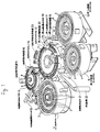
- the whole structure of an automatic biochemical analyzer in accordance with the present invention is shown in Fig. 1.
- the biochemical analyzer generally indicated by reference numeral 1, comprises a sample turntable 4, a diluting turntable 6, a first reagent turntable 8, a second reagent turntable 10, and a reaction turntable 12.
- a given number of sample containers 2 holding biological samples are set on the sample turntable 4.
- the samples are drawn from the sample containers 2 and diluted.
- the diluted samples are put in diluting containers 5, which in turn are set on the diluting turntable 6.
- Reagent containers 7 holding first and fourth reagents of different kinds are set on the reagent turntable 8.
- Reagent containers 9 holding second and third reagents of different kinds are set on the second reagent turntable 10.
- a given number of reaction containers 11 are set on the reaction turntable 12.
- sample containers 2 are arranged in two rows and regularly spaced from each other by one pitch. Each row consists of 42 sample containers 2. This sample turntable 4 is rotated incrementally, one pitch at a time.
- a diluting pipette 13 is mounted between the sample turntable 4 and the diluting turntable 6 and reciprocated between the sample turntable 4 and the diluting turntable 6 by a drive mechanism (not shown).
- the diluting pipette 13 is moved up and down for aspirating and injecting operations.
- a sampling pump (not shown) is operated to take in a given amount of sample. Then, the diluting pipette 13 obtains access to one diluting container 5 in a given position on the diluting turntable 6.
- a given amount of diluent (normally physiological salt solution) supplied from the diluting pipette 13 itself is injected into the diluting container 5, along with the sample.
- the sample is diluted by a given factor within the diluting container 5.
- the diluting pipette 13 is washed by a washing device (not shown) located at the midway location in the reciprocating stroke of the pipette.
- a sampling pipette 14, a stirring device 15, and a washing device 16 are mounted around the diluting turntable 6, as well as the diluting pipette 13.
- the diluted sample in the diluting container 5 is stirred by the stirring device 15, thus producing a uniform diluted sample.
- N be the number of the diluting containers 5 circumferentially arranged on the diluting turntable 6.
- the diluting turntable 6 is rotated incrementally, M pitches at a time. To arrange these devices 13, 14, 15, and 16 with sufficient degrees of freedom, M and N are so selected as not to have any common factor.
- a drive mechanism reciprocates the sampling pipette 14 between the diluting turntable 6 and the reaction turntable 12 through the dilution washing device 16.
- a diluting sampling pump (not shown) is operated to drawn in a given amount of diluted sample.
- the sampling pipette 14 is lowered to obtain access to one reaction container 11 in a given position on the reaction turntable 12, and the pipette 14 injects the drawn diluted sample into the reaction container 11.
- the stirring device 15 is moved up and down by a vertical driving mechanism (not shown) and has a stirring rod (not shown) reciprocating diametrically of the diluting turntable 6.
- the stirring rod of the diluting turntable 6 advances into a diluted sample in the diluting container 5 and moves back and forth to produce a uniform diluted sample.
- the washing device 16 cleanses the sampling pipette 14 after the diluted sample is injected into the reaction container 11.
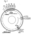
- reaction containers 11 are disposed along the whole outer periphery of the reaction turntable 12.
- Numerals 1 through 221 are given to 221 positions taken in a counterclockwise direction along the outer surface of the reaction turntable 12.
- a first reagent is injected at position 1.
- a fourth reagent is injected at position 2.
- the first reagent is stirred at position 4.
- the fourth reagent is stirred at position 5.
- a third reagent is injected at position 36.
- a second reagent is injected at position 37.
- the third reagent is stirred at position 39.
- the second reagent is stirred at position 40.
- the reaction container 11 is washed and checked for contamination at positions 80-107.
- a diluted sample is injected at position 113.
- the pipettes 14, 17, 18, the stirring devices 19, 20, and the washing device 23 perform their operations on the reaction container 11 halted at the positions described above.
- the reagent pipette 17 is reciprocated between the reaction turntable 12 and the reagent turntable 8 by a driving mechanism (not shown).
- a driving mechanism (not shown)
- the reagent pipette 17 is lowered and obtains access to the reagent container 7 located at a given position on the reagent turntable 8.
- a reagent pump (not shown) is operated to draw in a given amount of reagent.
- the pipette rotates toward the reaction turntable 12.
- the pipette is lowered to get access to the reaction container 11 positioned at a given location on the reaction turntable 12.
- the drawn reagent is injected as the first reagent into the reaction container 11.
- the reagent pipette 17 operates similarly when the fourth reagent held in other reagent container 7 is pipetted into the reaction container 11. As mentioned previously, the position at which the fourth reagent is pipetted differs from the position at which the first reagent is pipetted. That is, the reagent pipette 17 is designed so that it can come to a halt at two pipetting positions.
- the stirring device 19 is moved up and down by a driving mechanism (not shown) and has a stirring rod (not shown) that is rotated and moved back and forth.
- the stirring rod is advanced into the reaction container 11 in a given position on the reaction turntable 12 and then rotated and moved back and forth diametrically of the reaction turntable 12. This assures that the first reagent induces a uniform reaction of the diluted sample.
- the stirring device 19 similarly stirs the diluted sample and the fourth reagent inside the reaction container 11. As described above, the position at which the fourth reagent is stirred is different from the position at which the first reagent is stirred.
- the reagent pipette 18 draws the second or third reagent from the second reagent turntable 10 and injects the drawn reagent into the reaction container located in a given position on the reaction turntable, in exactly the same way as the reagent pipette 17.
- the stirring device 20 stirs the second or third reagent and the diluted sample in the reaction container, in exactly the same manner as the stirring device 19.
- the multi-wavelength photometer 21 measures the absorbance of the diluted sample inside the reaction container 11 and detects the reaction products arising from the diluted sample in the reaction container 11.
- the thermostatic chamber 22 maintains constant the temperature of the reaction containers 11 on the reaction turntable 12 at all times.
- the washing device 23 uses a draining pump (not shown) to draw in the detected diluted sample and reagent held in the reaction container 11.
- the drawn sample and reagent are discharged into a draining tank.
- a detergent pump (not shown) supplies a detergent into this reaction container 11 to wash the interior of the reaction container 11.
- the detergent is then drawn off into the draining tank. At this time, the degree of contamination of the reaction container 11 is measured. If it is heavily contaminated, a warning is issued to replace the container.
- N be the number of the reaction containers 11 circumferentially arranged on the reaction turntable 12.
- This reaction turntable 12 is rotated incrementally, M pitches at a time.
- M and N are so selected as not to have any common factor.
- the reaction turntable 12 is rotated through more than 180 degrees in one step.
- the 221 reaction containers 11 are rotated in 112 pitches in one step.
- Fig. 3 is a fragmentary schematic enlarged view of the reagent pipette 17 and the stirring device 19 of the analyzer shown in Fig. 1.
- the reagent pipette 17 is rotated along a trajectory indicated by an arc in Fig. 3. This pipette 17 can be halted either at position 1 or at position 2 by selecting the angle through which the pipette rotates at a time.
- the reagent pipette 17 can pipette a first reagent into the reaction container 11.
- the reagent pipette 17 can inject a fourth reagent into the reaction container 11.
- the stirring device 19 can move one pitch (i.e., the distance between the successive reaction containers 11) straightly between positions 4 and 5 along a straight line tangent to the outer surface of the reaction turntable 12.
- the stirring device 19 may also move in a slightly curved path along the outer surface of the reaction turntable 12.
- the reagent pipette 18 and stirring device 20 that are put in parentheses in Fig. 3 are constructed similarly to the reagent pipette 17 and stirring device 19, respectively, shown in Fig. 3.
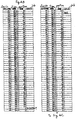
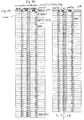
- the present example of reagent-injecting-and-stirring device constructed in this way performs various operations on one reaction container at the timing illustrated in Figs. 4A-4C.
- M pitches e.g., 112 pitches.
- M does not have any common factor with the total number, or 221, of the reaction containers 11.
- M is in excess of half of the total number.
- the reaction turntable 12 rotates in one step the turntable rotates in 112 pitches and comes to a halt.
- This series of operations is repeated at intervals of 3 seconds, as shown in Fig. 7 (a).
- the reaction turntable is rotated.
- the turntable is halted, and a set of operations is performed.
- One sequence of operations is completed in 221 steps in 3 seconds ⁇ 221.
- steps 1, 2, and 3 each have an upper column and a lower column.
- the upper column indicates a position assumed before rotation, while the lower column indicates a position taken after rotation.
- the remaining steps each have one column indicating a position taken before rotation.
- step 1 some reaction container 11A comes to a halt at position 1 after rotation of the reaction turntable.
- the reagent pipette 17 gains access to this reaction container 11A.
- a first reagent previously aspirated is injected into the container 11A (R1) (see Fig. 3). At this time, any diluted sample is not yet injected into the reaction container 11A.
- step 2 the reaction turntable 12 rotates in 112 pitches.
- the reaction container 11A into which the first reagent was pipetted at position 1 is halted at a diluted sample-injecting position 113.
- the sampling pipette 14 gets access to the reaction container 11A and pipettes a diluted sample into the reaction container 11A (S).
- a nozzle (not shown) mounted at the front end of the sampling pipette 14 is advanced into the first reagent.
- the diluted sample is injected into the first reagent.
- the nozzle is withdrawn from the first reagent.
- a slight amount of the first reagent adheres to the outer surface of the nozzle at the front end. Since the amount of the first reagent is greater than the amount of the diluted sample, the adhesion of the first reagent hardly affects the reaction of the diluted sample with the first reagent.
- step 3 the reaction turntable 12 is rotated in 112 pitches and comes to a halt.
- the reaction container 11A passes in front of the multi-wavelength photometer 21, which in turn measures the absorbance of the mixture of the diluted sample and the reagent inside the reaction container 11A.
- the photometer 21 performs a similar measurement.
- the reaction container 11A arrives at a first stirring position 4 (Fig. 3).
- the stirring device 19 stirs the diluted sample and the first reagent in the reaction container 11A (R1MIX).
- the stirring rod of the stirring device 19 is lowered into the diluted sample and first reagent in the container 11A.
- the stirring rod is rotated and reciprocated back and forth diametrically of the reaction turntable 12. The rotation and reciprocating movement of the stirring rod, done longitudinally of the reaction container, make the stirring operation efficient.
- step 4 the reaction turntable 12 is rotated in 112 pitches and comes to a halt.
- the reaction container 11A having the first reagent already stirred in step 3 is at position 116. At this time, the reaction container 11A is not processed at all. In this way, the reaction turntable 12 is rotated in 112 pitches, brought to a halt, and stirring is done in a sequence of steps in 3 seconds, for example. This sequence of steps is repeated at regular intervals.
- step 25 the reaction turntable 12 comes to a halt, and the reaction container 11A arrives at a second reagent-injecting position 37 (Fig. 3).
- the reagent pipette 18 injects the second reagent in the same way as the injection of the first reagent (R2).
- step 27 the reaction turntable 12 comes to a halt, and the reaction container 11A comes to a halt at the second stirring position 40.
- the stirring device (20) stirs the second reagent (R2MIX) in the same way as the stirring (R1MIX) of the first reagent by the stirring device 19.
- step 98 the reaction turntable 12 comes to a halt, and the reaction container 11A arrives at a third reagent-injecting position (36). Since this third reagent-injecting position (36) is adjacent to the second reagent-injecting position (37), the reagent pipette (18) is rotated to this third reagent-injecting position, and then the reagent pipette (18) (R3) injects the third reagent.
- step 100 the reaction turntable 12 comes to a halt, and the reaction container 11A reaches a third stirring position (39) adjacent to the second stirring position (40).
- the stirring device (20) is rotated in one pitch up to the third stirring position along a straight line tangent to the outer surface of the reaction turntable 12.
- the stirring device 20 stirs the third reagent (R3MIX).
- step 149 the reaction turntable 12 comes to a halt, and the reaction container 11A reaches a fourth reagent-injecting position 2 (Fig. 3) adjacent to the first reagent-injecting position 1.
- the reagent pipette 17 is rotated to this fourth reagent-injecting position and then injects the fourth reagent (R4).
- step 151 the reaction turntable 12 comes to a halt, and the reaction container 11A arrives at the fourth stirring position 5 adjacent to the first stirring position 4.
- the stirring device 19 is moved one pitch straight along the straight line tangent to the outer surface of the reaction turntable 12 and assumes a state indicated by the phantom lines in Fig. 2. Then, the stirring device 19 can stir the fourth reagent (R4MIX).
- the photometer 21 detects reaction products arising from the diluted sample in response to each reagent. These measurements end before step 201. Then, the reaction container 11A used for measurements is washed. More specifically, a cleaning device 23 washes the reaction container 11A (WD1, WD2, WD3, WD4, WD5, and WD6), using an alkaline detergent, an acidic detergent, or pure water, at positions 80, 83, 86, 89, 92, and 95, respectively, in steps 201, 203, 205, 207, 209, and 211, respectively.
- steps 214 and 216 the degree of contamination of each reaction container 11 is measured, using physiological salt solution at positions 98 and 101, respectively.
- steps 217 and 219 the cleaning device 23 discharges liquid from the reaction container 11 at positions 104 and 107, respectively. In this way, the measurement of the sample in one reaction container 11A is completed.
- reaction containers successively moved into position 1 subsequently to the reaction container 11A are treated similarly at intervals of one step.
- the reaction turntable 12 is rotated in 112 pitches in one step. It is to be noted that 112 does not have any common factor with the total number, or 221, of the reaction containers 11. This increases the degrees of freedom in designing the instrument. As a result, the two positions at which two kinds of reagents are pipetted or stirred can be made adjacent to each other around the reaction turntable. Consequently, four kinds of reagents can be pipetted and stirred by two reagent pipettes and two stirring devices. Hence, the instrument can be made up of less number of components than heretofore. Also, the cost can be curtailed.
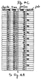
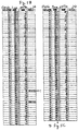
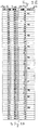
- Figs. 5A-5E are diagrams illustrating an example of timing of a sequence of operations performed on one reaction container in the same manner as in the example of Figs. 4A-4C.
- the turntable is rotated in 112 pitches in one step similarly to the example of Figs. 4A-4C but the period of the 112 pitches is divided into a former operative period corresponding to earlier 45 pitches and a latter operative period corresponding to latter 67 pitches.
- Two halt periods are placed between these two operative periods. An operation can be carried out during each halt period.
- the total period consisting of the two operative periods and the two halt periods is set, for example, to 4.5 seconds.
- the control mechanism for operating the instrument at the timing illustrated in Figs. 5A-5E is the same as the control mechanism of Fig. 1.
- reaction turntable 12 As the reaction turntable 12 is rotated one revolution in 221 steps, one reaction container 11 brought to a halt at position 1 in step 1 is again halted at position 1 in step 193.
- the reaction container 11 halted at position 2 in step 119 is again brought to a halt at position 2 in step 149.
- the reaction container 11 halted at position 4 in step 3 is again halted at position 4 in step 195.
- the reaction container 11 halted at position 5 in step 121 is again halted at position 5 in step 151.
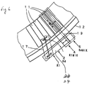
- FIG. 6 there is shown another reagent-injecting-and-stirring device for use with an automatic biochemical analyzer.
- Fig. 6 is a fragmentary enlarged view similar to Fig. 3.
- the reagent pipette 17 is rotated so that it can inject aliquots of reagent into reaction containers 11 either at position 1 or at position 2.
- the stirring device 19 is linearly moved one pitch back and forth so that it can stir the liquid either at position 4 or at position 5.
- the reagent pipette 17 is rotated so that it can inject aliquots of reagent into the reaction containers 11 only at one position 1 or 2.
- the reagent pipette 17 can linearly move one pitch back and forth along the tangential line to the outer surface of the reaction turntable 12.
- the first reagent pipette 17 and the first reaction stirring device 19 are held to a common support base 24.
- reagent pipette 17 or 18 can move one pitch back and forth, together with the stirring device 19 or 20.
- the configuration of Fig. 6 can be applied to any timing scheme of reagent injection and stirring illustrated in Figs. 4A-4C, 5A-5E.
- the reaction turntable is rotated in M pitches in one step, it being noted that M and N (the total number of reaction containers on the reaction turntable) do not have any common factor.
- Two adjacent positions can be established as first and second reagent-injecting positions where the reagent pipette can inject aliquots of reagent into reaction containers.
- two adjacent positions can be established as first and second stirring positions where a stirring device can stir liquid in reaction containers.
- One reagent pipette is moved between these two established first and second injecting positions.
- One stirring device is moved between these two established first and second stirring positions. Consequently, it is possible to inject two kinds of reagents with only one reagent pipette and one stirring device.
- the number of the components of the instrument can be reduced. This can lead to a decrease in the cost.
- reagents can be injected and stirred by dividing one stepwise movement into a former stepwise movement and a latter stepwise movement with at least one intervening halt period.
Abstract
Description
Claims (8)
- An automatic biochemical analyzer comprising:a sample turntable on which a plurality of sample containers for holding samples are arrayed, said sample containers being N in number;a reaction turntable on which a plurality of reaction containers for holding reagents are substantially regularly spaced from each other by one pitch circumferentially, said reaction turntable being rotated in M pitches at a time, said M and said N being so selected that they do not have any common factor;a sampling pipette for drawing in a sample aliquot from a selected one of said sample containers and injecting the drawn sample aliquot into a selected one of said reaction containers;a reagent pipette for drawing in an aliquot of a selected one of said reagents and injecting the drawn reagent aliquot into said selected reaction container at any one of first and second injecting positions adjacent to each other;a stirring device for stirring said sample aliquot and said reagent aliquot in said selected reagent container at any one of first and second stirring positions adjacent to each other, said stirring device being capable of moving between said first and second stirring positions; anda detector for detecting reaction products arising from said sample aliquot after the stirring.
- The automatic biochemical analyzer of claim 1, further comprising a diluting means for once diluting the sample aliquot drawn from said selected sample container so that diluted sample is injected into the selected reaction container by said sampling pipette.
- The automatic biochemical analyzer of claim 1 or 2, wherein said reaction containers are 221 in number, and wherein said reaction turntable is rotated in 112 pitches in one step.
- The automatic biochemical analyzer of claim 3, wherein when said turntable is rotated in 112 pitches in one step, said turntable is first rotated in 45 pitches, halted for a given period of time, and then rotated in 67 pitches.
- The automatic biochemical analyzer of any one of claims 1-4, wherein said reagent pipette can be moved between said first and second injecting positions.
- The automatic biochemical analyzer of claim 5, wherein said reagent pipette is moved one pitch between said first and second injecting positions and said stirring device is moved one pitch between said first and second stirring positions by a common driving mechanism.
- The automatic biochemical analyzer of any one of claims 1-6, wherein third and fourth injecting positions adjacent to each other and independent of said first and second injecting positions are established as injecting positions where a second reagent pipette injects a reagent into said selected reaction container, and wherein third and fourth stirring positions adjacent to each other and independent of said first and second stirring positions are established as stirring positions where a second stirring device stirs liquids in said selected reaction container, said second stirring device being capable of moving between said third and fourth stirring positions.
- The automatic biochemical analyzer of claim 7, wherein said second reagent pipette can be moved between said third and fourth injecting positions.
Applications Claiming Priority (2)
| Application Number | Priority Date | Filing Date | Title |
|---|---|---|---|
| JP219739/96 | 1996-08-21 | ||
| JP21973996A JP3419430B2 (en) | 1996-08-21 | 1996-08-21 | Reagent injection mixer for biochemical automatic analyzer |
Publications (3)
| Publication Number | Publication Date |
|---|---|
| EP0825445A2 true EP0825445A2 (en) | 1998-02-25 |
| EP0825445A3 EP0825445A3 (en) | 1998-09-16 |
| EP0825445B1 EP0825445B1 (en) | 2006-12-06 |
Family
ID=34685709
Family Applications (1)
| Application Number | Title | Priority Date | Filing Date |
|---|---|---|---|
| EP97306356A Expired - Lifetime EP0825445B1 (en) | 1996-08-21 | 1997-08-20 | Automatic biochemical analyzer |
Country Status (5)
| Country | Link |
|---|---|
| US (1) | US6146592A (en) |
| EP (1) | EP0825445B1 (en) |
| JP (1) | JP3419430B2 (en) |
| CA (1) | CA2213595C (en) |
| DE (1) | DE69737052T2 (en) |
Cited By (2)
| Publication number | Priority date | Publication date | Assignee | Title |
|---|---|---|---|---|
| EP1538446A2 (en) * | 2003-12-05 | 2005-06-08 | Hitachi High-Technologies Corporation | Automatic analyzer and analysis method |
| EP2096446A3 (en) * | 2008-02-27 | 2011-02-23 | Hitachi High-Technologies Corporation | Automatic analyzer |
Families Citing this family (44)
| Publication number | Priority date | Publication date | Assignee | Title |
|---|---|---|---|---|
| US8337753B2 (en) | 1998-05-01 | 2012-12-25 | Gen-Probe Incorporated | Temperature-controlled incubator having a receptacle mixing mechanism |
| EP1614475B1 (en) | 1998-05-01 | 2007-05-30 | Gen-Probe Incorporated | Device for agitating the fluid contents of a container |
| JP3603019B2 (en) * | 2000-12-15 | 2004-12-15 | 株式会社日立製作所 | Biochemical automatic analyzer |
| CA2871777C (en) | 2005-03-10 | 2015-07-28 | Matthew J. Hayes | System and methods for detecting multiple optical signals |
| US7998751B2 (en) * | 2005-04-26 | 2011-08-16 | Siemens Healthcare Diagnostics Inc. | Method and apparatus for aspirating and dispensing small liquid samples in an automated clinical analyzer |
| JP2007040843A (en) * | 2005-08-03 | 2007-02-15 | Hitachi High-Technologies Corp | Autoanalyzer |
| US7789552B2 (en) * | 2005-08-18 | 2010-09-07 | Hach Company | Particulate tester with mixer for analytical application |
| JP2007057318A (en) * | 2005-08-23 | 2007-03-08 | Olympus Corp | Analyzer, feeder, stirring device and stirring method |
| JP4955301B2 (en) * | 2006-05-10 | 2012-06-20 | 株式会社日立ハイテクノロジーズ | Chemical analyzer |
| US9047545B2 (en) * | 2007-11-13 | 2015-06-02 | Medica Corporation | Modular chemistry analyzer |
| JP2009270941A (en) * | 2008-05-08 | 2009-11-19 | Hitachi High-Technologies Corp | Automatic analysis apparatus |
| EP2320238B1 (en) * | 2008-07-31 | 2020-09-23 | Hitachi High-Tech Corporation | Automatic analyzing device |
| CN101726616B (en) * | 2008-10-31 | 2014-07-16 | 深圳迈瑞生物医疗电子股份有限公司 | Automatic analytic device and working method thereof |
| KR101358549B1 (en) | 2009-11-13 | 2014-02-05 | 벤타나 메디컬 시스템즈, 인코포레이티드 | Thin film processing apparatuses for adjustable volume accommodation |
| US9498791B2 (en) | 2009-11-13 | 2016-11-22 | Ventana Medical Systems, Inc. | Opposables and automated specimen processing systems with opposables |
| US10746752B2 (en) | 2009-11-13 | 2020-08-18 | Ventana Medical Systems, Inc. | Opposables and automated specimen processing systems with opposables |
| WO2014102160A1 (en) * | 2012-12-26 | 2014-07-03 | Ventana Medical Systems, Inc. | Automated specimen processing systems and methods of using the same |
| DE102009046762A1 (en) * | 2009-11-17 | 2011-05-26 | Diasys Technologies S.A.R.L. | Configuration and operation of an automated analysis device |
| US9046507B2 (en) | 2010-07-29 | 2015-06-02 | Gen-Probe Incorporated | Method, system and apparatus for incorporating capacitive proximity sensing in an automated fluid transfer procedure |
| WO2012116308A1 (en) | 2011-02-24 | 2012-08-30 | Gen-Probe Incorporated | Systems and methods for distinguishing optical signals of different modulation frequencies in an optical signal detector |
| US11274998B2 (en) | 2012-12-26 | 2022-03-15 | Ventana Medical Systems, Inc. | Specimen processing systems and methods for holding slides |
| US9989448B2 (en) | 2012-12-26 | 2018-06-05 | Ventana Medical Systems, Inc. | Specimen processing systems and methods for holding slides |
| US9400285B2 (en) | 2013-03-15 | 2016-07-26 | Abbot Laboratories | Automated diagnostic analyzers having vertically arranged carousels and related methods |
| JP6165961B2 (en) | 2013-03-15 | 2017-07-19 | アボット・ラボラトリーズAbbott Laboratories | Diagnostic analyzer with pre-process carousel and associated method |
| ES2901756T3 (en) | 2013-03-15 | 2022-03-23 | Abbott Lab | Automated diagnostic analyzers having rear accessible track systems and related methods |
| USD728120S1 (en) | 2013-03-15 | 2015-04-28 | Ventana Medical Systems, Inc. | Arcuate member for moving liquids along a microscope slide |
| JP5805136B2 (en) * | 2013-05-16 | 2015-11-04 | 株式会社堀場製作所 | Whole blood blood cell immunoassay device |
| JP5771236B2 (en) * | 2013-05-17 | 2015-08-26 | 株式会社堀場製作所 | Blood analyzer |
| CN105659070B (en) * | 2013-10-17 | 2019-06-14 | 西门子医疗保健诊断公司 | Close-coupled high capacity analysis instrument framework |
| JP6312313B2 (en) * | 2014-04-17 | 2018-04-18 | 日本電子株式会社 | Automatic analyzer and automatic analysis method |
| CN103969459B (en) * | 2014-04-22 | 2015-08-19 | 深圳市库贝尔生物科技有限公司 | A kind of full-automatic biochemical analysis method |
| WO2016130964A1 (en) | 2015-02-13 | 2016-08-18 | Abbott Laboratories | Decapping and capping apparatus, systems and methods for use in diagnostic analyzers |
| CA3197270A1 (en) | 2016-02-17 | 2017-08-24 | Becton, Dickinson And Company | Automated sample preparation system for diagnostic testing of same |
| CN109073664B (en) | 2016-04-22 | 2022-12-06 | 贝克顿·迪金森公司 | Automated diagnostic analyzer and method of operating the same |
| CN207067156U (en) | 2016-04-22 | 2018-03-02 | 贝克顿·迪金森公司 | automated diagnostic analyzer |
| EP3598142A4 (en) * | 2017-03-14 | 2020-12-23 | Hitachi High-Tech Corporation | Automated analysis device |
| WO2020098959A1 (en) * | 2018-11-16 | 2020-05-22 | Aixinno Limited | Module for an automated biology laboratory system with an interface to transfer microplates or lab-ware |
| JP2022518101A (en) * | 2018-11-16 | 2022-03-14 | アイキシンノ・リミテッド | Process module for automated biological systems |
| WO2020098960A1 (en) * | 2018-11-16 | 2020-05-22 | Aixinno Limited | A system for processing biology material, comprising a plurality of uniform design storage modules |
| DE102019134002A1 (en) | 2019-12-11 | 2021-06-17 | Aixinno Limited | Device for the treatment of biological cell cultures |
| DE102019134003A1 (en) | 2019-12-11 | 2021-06-17 | Aixinno Limited | Method and device for culturing biological cells |
| EP4070069A4 (en) * | 2020-02-27 | 2023-09-06 | Molarray Research Inc. | System and apparatus for automated sample extracting of biological specimens |
| CN112924703A (en) * | 2021-01-26 | 2021-06-08 | 英华达(上海)科技有限公司 | Pipetting system and pipetting operation method thereof |
| CN114167071A (en) * | 2022-02-10 | 2022-03-11 | 广州科方生物技术股份有限公司 | Multifunctional sample analysis system |
Citations (8)
| Publication number | Priority date | Publication date | Assignee | Title |
|---|---|---|---|---|
| EP0100663A2 (en) * | 1982-07-30 | 1984-02-15 | Corning Glass Works | Dilution cups for spectrophotometer analyzer |
| US4459265A (en) * | 1980-06-25 | 1984-07-10 | Clinicon Ab | Automatically operating analysis apparatus |
| US4647432A (en) * | 1982-11-30 | 1987-03-03 | Japan Tectron Instruments Corporation Tokuyama Soda Kabushiki Kaisha | Automatic analysis apparatus |
| US4908320A (en) * | 1986-07-11 | 1990-03-13 | Beckman Instruments, Inc. | Analyzer operating method |
| EP0488247A2 (en) * | 1990-11-28 | 1992-06-03 | Hitachi, Ltd. | Analyzing method and apparatus for liquid sample |
| US5183638A (en) * | 1989-12-04 | 1993-02-02 | Kabushiki Kaisha Nittec | Automatic immunity analysis apparatus with magnetic particle separation |
| US5212094A (en) * | 1986-09-16 | 1993-05-18 | Kabushiki Kaisha Toshiba | Automatic chemical analyzer |
| US5352612A (en) * | 1993-02-09 | 1994-10-04 | Baxter Diagnostics Inc. | Method and apparatus for the stepwise movement of items |
Family Cites Families (5)
| Publication number | Priority date | Publication date | Assignee | Title |
|---|---|---|---|---|
| JP3229915B2 (en) * | 1995-01-19 | 2001-11-19 | 日本電子株式会社 | Biochemical automatic analyzer |
| US5741461A (en) * | 1995-05-19 | 1998-04-21 | Hitachi, Ltd. | Automatic analyzer having cuvette cleaning control device |
| JP3063584B2 (en) * | 1995-09-05 | 2000-07-12 | 株式会社日立製作所 | Automatic analyzer |
| JP3001087B2 (en) * | 1995-10-18 | 2000-01-17 | 株式会社日立製作所 | Automatic analyzer and method |
| US5679309A (en) * | 1995-12-14 | 1997-10-21 | Beckman Instruments, Inc. | Automated random access analyzer |
-
1996
- 1996-08-21 JP JP21973996A patent/JP3419430B2/en not_active Expired - Fee Related
-
1997
- 1997-08-20 EP EP97306356A patent/EP0825445B1/en not_active Expired - Lifetime
- 1997-08-20 DE DE69737052T patent/DE69737052T2/en not_active Expired - Lifetime
- 1997-08-21 CA CA002213595A patent/CA2213595C/en not_active Expired - Lifetime
- 1997-08-21 US US08/916,090 patent/US6146592A/en not_active Expired - Lifetime
Patent Citations (8)
| Publication number | Priority date | Publication date | Assignee | Title |
|---|---|---|---|---|
| US4459265A (en) * | 1980-06-25 | 1984-07-10 | Clinicon Ab | Automatically operating analysis apparatus |
| EP0100663A2 (en) * | 1982-07-30 | 1984-02-15 | Corning Glass Works | Dilution cups for spectrophotometer analyzer |
| US4647432A (en) * | 1982-11-30 | 1987-03-03 | Japan Tectron Instruments Corporation Tokuyama Soda Kabushiki Kaisha | Automatic analysis apparatus |
| US4908320A (en) * | 1986-07-11 | 1990-03-13 | Beckman Instruments, Inc. | Analyzer operating method |
| US5212094A (en) * | 1986-09-16 | 1993-05-18 | Kabushiki Kaisha Toshiba | Automatic chemical analyzer |
| US5183638A (en) * | 1989-12-04 | 1993-02-02 | Kabushiki Kaisha Nittec | Automatic immunity analysis apparatus with magnetic particle separation |
| EP0488247A2 (en) * | 1990-11-28 | 1992-06-03 | Hitachi, Ltd. | Analyzing method and apparatus for liquid sample |
| US5352612A (en) * | 1993-02-09 | 1994-10-04 | Baxter Diagnostics Inc. | Method and apparatus for the stepwise movement of items |
Cited By (4)
| Publication number | Priority date | Publication date | Assignee | Title |
|---|---|---|---|---|
| EP1538446A2 (en) * | 2003-12-05 | 2005-06-08 | Hitachi High-Technologies Corporation | Automatic analyzer and analysis method |
| EP1538446A3 (en) * | 2003-12-05 | 2005-09-21 | Hitachi High-Technologies Corporation | Automatic analyzer and analysis method |
| EP2096446A3 (en) * | 2008-02-27 | 2011-02-23 | Hitachi High-Technologies Corporation | Automatic analyzer |
| US8343423B2 (en) | 2008-02-27 | 2013-01-01 | Hitachi High-Technologies Corporation | Automatic analyzer |
Also Published As
| Publication number | Publication date |
|---|---|
| JP3419430B2 (en) | 2003-06-23 |
| EP0825445B1 (en) | 2006-12-06 |
| DE69737052D1 (en) | 2007-01-18 |
| CA2213595C (en) | 2001-10-02 |
| DE69737052T2 (en) | 2007-05-16 |
| EP0825445A3 (en) | 1998-09-16 |
| US6146592A (en) | 2000-11-14 |
| JPH1062429A (en) | 1998-03-06 |
| CA2213595A1 (en) | 1998-02-21 |
Similar Documents
| Publication | Publication Date | Title |
|---|---|---|
| EP0825445B1 (en) | Automatic biochemical analyzer | |
| CA2212903C (en) | Washing device for automatic biochemical analyzer | |
| US5876668A (en) | Automatic biochemical analyzer | |
| EP1007972B1 (en) | Automatic chemistry analyzer | |
| JP2539512B2 (en) | Multi-item analyzer and method for operating the analyzer | |
| EP2535720B1 (en) | Instrument and Method for Clinical Examinations and Cleaning Method Therefor | |
| US6409968B1 (en) | Automatic analysis apparatus for biological fluid sample and automatic analysis method therefor | |
| JP3914837B2 (en) | Automatic analyzer | |
| US20090137048A1 (en) | Automatic analyzer and analysis method for use in the same | |
| CA2213587C (en) | Pipette-washing device for automatic biochemical analyzer | |
| ZA200600492B (en) | Method for increasing capacity in an automatic clinical analyzer by using modular reagent delivery means | |
| JP4102739B2 (en) | Automatic analyzer | |
| WO2003012454A1 (en) | Increasing throughput in an automatic clinical analyzer by partitioning assays according to type | |
| KR20040085068A (en) | Analyzer having a stationary multifunction probe | |
| WO2005008217A9 (en) | Method for increasing capacity in an automatic clinical analyzer by using modular reagent delivery means | |
| EP1536880A2 (en) | Method and apparatus for mixing liquid samples using a sinusoidal mixing action | |
| US4523484A (en) | Dilution pipetter | |
| JP2815433B2 (en) | Automatic analyzer | |
| JPH1062430A (en) | Stirrer in automatic biochemical analyzer | |
| JP4408404B2 (en) | Automatic analyzer | |
| JP4146873B2 (en) | Automatic analyzer | |
| JPH02173570A (en) | Automatic chemical analyzer | |
| JP4410644B2 (en) | Biochemical automatic analyzer | |
| JPH03194468A (en) | Automatic analyzer | |
| JP4538487B2 (en) | Automatic analyzer |
Legal Events
| Date | Code | Title | Description |
|---|---|---|---|
| PUAI | Public reference made under article 153(3) epc to a published international application that has entered the european phase |
Free format text: ORIGINAL CODE: 0009012 |
|
| AK | Designated contracting states |
Kind code of ref document: A2 Designated state(s): DE FR GB |
|
| PUAL | Search report despatched |
Free format text: ORIGINAL CODE: 0009013 |
|
| AK | Designated contracting states |
Kind code of ref document: A3 Designated state(s): AT BE CH DE DK ES FI FR GB GR IE IT LI LU MC NL PT SE |
|
| 17P | Request for examination filed |
Effective date: 19990209 |
|
| AKX | Designation fees paid |
Free format text: DE FR GB |
|
| RBV | Designated contracting states (corrected) |
Designated state(s): DE FR GB |
|
| GRAP | Despatch of communication of intention to grant a patent |
Free format text: ORIGINAL CODE: EPIDOSNIGR1 |
|
| GRAS | Grant fee paid |
Free format text: ORIGINAL CODE: EPIDOSNIGR3 |
|
| GRAA | (expected) grant |
Free format text: ORIGINAL CODE: 0009210 |
|
| AK | Designated contracting states |
Kind code of ref document: B1 Designated state(s): DE FR GB |
|
| REG | Reference to a national code |
Ref country code: GB Ref legal event code: FG4D |
|
| REF | Corresponds to: |
Ref document number: 69737052 Country of ref document: DE Date of ref document: 20070118 Kind code of ref document: P |
|
| ET | Fr: translation filed | ||
| PLBE | No opposition filed within time limit |
Free format text: ORIGINAL CODE: 0009261 |
|
| STAA | Information on the status of an ep patent application or granted ep patent |
Free format text: STATUS: NO OPPOSITION FILED WITHIN TIME LIMIT |
|
| 26N | No opposition filed |
Effective date: 20070907 |
|
| REG | Reference to a national code |
Ref country code: FR Ref legal event code: PLFP Year of fee payment: 20 |
|
| PGFP | Annual fee paid to national office [announced via postgrant information from national office to epo] |
Ref country code: GB Payment date: 20160817 Year of fee payment: 20 Ref country code: DE Payment date: 20160816 Year of fee payment: 20 |
|
| PGFP | Annual fee paid to national office [announced via postgrant information from national office to epo] |
Ref country code: FR Payment date: 20160712 Year of fee payment: 20 |
|
| REG | Reference to a national code |
Ref country code: DE Ref legal event code: R071 Ref document number: 69737052 Country of ref document: DE |
|
| REG | Reference to a national code |
Ref country code: GB Ref legal event code: PE20 Expiry date: 20170819 |
|
| PG25 | Lapsed in a contracting state [announced via postgrant information from national office to epo] |
Ref country code: GB Free format text: LAPSE BECAUSE OF EXPIRATION OF PROTECTION Effective date: 20170819 |