EP0825554A1 - Sealing device - Google Patents
Sealing device Download PDFInfo
- Publication number
- EP0825554A1 EP0825554A1 EP96202269A EP96202269A EP0825554A1 EP 0825554 A1 EP0825554 A1 EP 0825554A1 EP 96202269 A EP96202269 A EP 96202269A EP 96202269 A EP96202269 A EP 96202269A EP 0825554 A1 EP0825554 A1 EP 0825554A1
- Authority
- EP
- European Patent Office
- Prior art keywords
- loop
- sealing device
- broken
- codeword
- electronic component
- Prior art date
- Legal status (The legal status is an assumption and is not a legal conclusion. Google has not performed a legal analysis and makes no representation as to the accuracy of the status listed.)
- Withdrawn
Links
Images

Classifications
-
- G—PHYSICS
- G06—COMPUTING; CALCULATING OR COUNTING
- G06K—GRAPHICAL DATA READING; PRESENTATION OF DATA; RECORD CARRIERS; HANDLING RECORD CARRIERS
- G06K19/00—Record carriers for use with machines and with at least a part designed to carry digital markings
- G06K19/06—Record carriers for use with machines and with at least a part designed to carry digital markings characterised by the kind of the digital marking, e.g. shape, nature, code
- G06K19/067—Record carriers with conductive marks, printed circuits or semiconductor circuit elements, e.g. credit or identity cards also with resonating or responding marks without active components
- G06K19/07—Record carriers with conductive marks, printed circuits or semiconductor circuit elements, e.g. credit or identity cards also with resonating or responding marks without active components with integrated circuit chips
- G06K19/077—Constructional details, e.g. mounting of circuits in the carrier
- G06K19/07749—Constructional details, e.g. mounting of circuits in the carrier the record carrier being capable of non-contact communication, e.g. constructional details of the antenna of a non-contact smart card
- G06K19/07798—Constructional details, e.g. mounting of circuits in the carrier the record carrier being capable of non-contact communication, e.g. constructional details of the antenna of a non-contact smart card part of the antenna or the integrated circuit being adapted for rupturing or breaking, e.g. record carriers functioning as sealing devices for detecting not-authenticated opening of containers
-
- G—PHYSICS
- G06—COMPUTING; CALCULATING OR COUNTING
- G06K—GRAPHICAL DATA READING; PRESENTATION OF DATA; RECORD CARRIERS; HANDLING RECORD CARRIERS
- G06K19/00—Record carriers for use with machines and with at least a part designed to carry digital markings
- G06K19/06—Record carriers for use with machines and with at least a part designed to carry digital markings characterised by the kind of the digital marking, e.g. shape, nature, code
- G06K19/067—Record carriers with conductive marks, printed circuits or semiconductor circuit elements, e.g. credit or identity cards also with resonating or responding marks without active components
- G06K19/07—Record carriers with conductive marks, printed circuits or semiconductor circuit elements, e.g. credit or identity cards also with resonating or responding marks without active components with integrated circuit chips
- G06K19/0723—Record carriers with conductive marks, printed circuits or semiconductor circuit elements, e.g. credit or identity cards also with resonating or responding marks without active components with integrated circuit chips the record carrier comprising an arrangement for non-contact communication, e.g. wireless communication circuits on transponder cards, non-contact smart cards or RFIDs
-
- G—PHYSICS
- G06—COMPUTING; CALCULATING OR COUNTING
- G06K—GRAPHICAL DATA READING; PRESENTATION OF DATA; RECORD CARRIERS; HANDLING RECORD CARRIERS
- G06K19/00—Record carriers for use with machines and with at least a part designed to carry digital markings
- G06K19/06—Record carriers for use with machines and with at least a part designed to carry digital markings characterised by the kind of the digital marking, e.g. shape, nature, code
- G06K19/067—Record carriers with conductive marks, printed circuits or semiconductor circuit elements, e.g. credit or identity cards also with resonating or responding marks without active components
- G06K19/07—Record carriers with conductive marks, printed circuits or semiconductor circuit elements, e.g. credit or identity cards also with resonating or responding marks without active components with integrated circuit chips
- G06K19/073—Special arrangements for circuits, e.g. for protecting identification code in memory
-
- G—PHYSICS
- G06—COMPUTING; CALCULATING OR COUNTING
- G06K—GRAPHICAL DATA READING; PRESENTATION OF DATA; RECORD CARRIERS; HANDLING RECORD CARRIERS
- G06K19/00—Record carriers for use with machines and with at least a part designed to carry digital markings
- G06K19/06—Record carriers for use with machines and with at least a part designed to carry digital markings characterised by the kind of the digital marking, e.g. shape, nature, code
- G06K19/067—Record carriers with conductive marks, printed circuits or semiconductor circuit elements, e.g. credit or identity cards also with resonating or responding marks without active components
- G06K19/07—Record carriers with conductive marks, printed circuits or semiconductor circuit elements, e.g. credit or identity cards also with resonating or responding marks without active components with integrated circuit chips
- G06K19/077—Constructional details, e.g. mounting of circuits in the carrier
- G06K19/07749—Constructional details, e.g. mounting of circuits in the carrier the record carrier being capable of non-contact communication, e.g. constructional details of the antenna of a non-contact smart card
- G06K19/07758—Constructional details, e.g. mounting of circuits in the carrier the record carrier being capable of non-contact communication, e.g. constructional details of the antenna of a non-contact smart card arrangements for adhering the record carrier to further objects or living beings, functioning as an identification tag
- G06K19/0776—Constructional details, e.g. mounting of circuits in the carrier the record carrier being capable of non-contact communication, e.g. constructional details of the antenna of a non-contact smart card arrangements for adhering the record carrier to further objects or living beings, functioning as an identification tag the adhering arrangement being a layer of adhesive, so that the record carrier can function as a sticker
Definitions
- the present invention relates to a sealing device provided for being applied onto an object to be sealed, said device comprising an electronic component with a memory, which component is connected to a first loop comprising a communication means, said communication means being provided for communicating with reading means.
- Such a device is known from patent application PCT/EP92/02841.
- the memory of the electronic component is stored with a codeword, so that when its operation is checked by the reading means via the communication means in the form of a coil acting as an antenna, it sends out the stored codeword.
- the first loop or the electronic component Upon opening the object to which the sealing device is applied, the first loop or the electronic component will be broken, so that the electronic component is prevented from sending out its codeword when read. In this manner, it is detected that the sealing device has been broken.
- a drawback of this known device is that a communication, in this case comprising a codeword, is performed between the electronic component and the reading means only if the sealing device has not been broken. If the sealing device has been broken, the first loop will be broken and connection between the communication means and the electronic component will be broken, so that no communication can be performed. Consequently, difference can not be made between sealing devices whose operation has not been checked and broken sealing devices whose operation has been checked. In both cases, no communication has been performed between the sealing device and the reading means.
- the device according to the invention is characterised in that a second loop, connected to the electronic component, is provided for letting energy circulating through it and to be broken upon breaking said sealing device.
- this second loop forms the sealing part of the device.
- the electrical connection between the electronic component and the communication means remains, even if the second loop is broken, so that a communication between the reading means and the electronic component can still be performed.
- a communication between the sealing device and the reading means is performed.
- no communication is performed between the sealing device and the reading means. Consequently, difference can be made between broken sealing devices whose operation has been checked and sealing devices whose operation has not been checked.
- the sealing device according to the invention is provided for being powered by said reading means.
- This enables to form a simple compact sealing device which is only activated when communicating with the reading means and which is independent from an own power source, such as e.g. a battery, which would otherwise have to be provided on the sealing device.
- said second loop is connected in parallel with the first loop. This enables to have an electronic component which is only provided with two connection ports instead of four, for connecting the first loop and the second loop, without affecting the presence of two loops.
- a capacitance or an inductance is provided in the second loop. This enables to detect a difference of resonance frequency of the energy circulating through the first and the second loop. In case the object has been opened, the second loop will be broken so that energy will circulate only through the first loop, which gives another resonance frequency than in the case the second loop is intact.
- the device according to the invention comprises means provided for generating a first codeword upon establishing that the second loop is intact and a second codeword upon establishing that the second loop is broken. This forms an alternative to detect whether or not the sealing device has been broken.
- said memory is connected to counter means provided for memorising how many times the object, onto which the device has been applied, has been sealed. This enables to use the same sealing device to objects, which have to be opened several times at determined places during the travel between the originating place and the destination place, e.g. a container which has to be checked several times, such as for example several customs.
- a first identification codeword for identifying said device is stored in said memory. This enables to readily identify the device, which is useful in case a plurality of sealing devices, each having their own first identification codeword, have to be checked with the reading means.
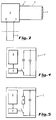
- Figure 1 is a schematic view of the sealing device according to a first preferred embodiment.
- Figure 2 is a schematic view of the sealing device according to a second preferred embodiment.
- Figure 3 is a schematic view of the sealing device according to a third preferred embodiment.
- Figure 4 is a detail of the electronic component of the sealing device.
- Figure 5 is a detail of the electronic component of the sealing device according to an alternative.
- the sealing device 1 is provided to be applied on an object to be sealed, such a for example a container or a valuable product. It comprises an electronic component 2, e.g. a microchip, provided with a memory 8 ( Figures 4 and 5).
- the electronic component is connected to a first loop 3 comprising a communication means, for example a coil 4.
- the coil 4 is provided for communicating with reading means (not illustrated).
- a second loop 5 is connected to the electronic component 2, either directly or in parallel with the first loop 3, and is provided for letting energy circulating through it and to break (illustrated by the dotted lines) upon breaking the sealing device.
- the advantage of having the second loop 5 connected in parallel with the first loop 3 is that only two in/outputs must be provided on the electronic component.
- the second loop is a galvanic conductive loop which preferably consists of a very thin wire having for example a section diameter of 30 ⁇ m. Such a thin wire prevents the second loop from being easily fraudulently fixed once it has been broken.
- the sealing device according to the invention is preferably passive, i.e. powered by the reading means, so that a very compact device can be made which is not dependent from the power of an own source, such as e.g. a battery, which would otherwise be provided in the sealing device.
- the second loop comprises further a capacitance 6 ( Figure 1) or an inductance 7 ( Figure 2).
- the reading means which comprises another communication means such as a coil
- the reading means is coupled, e.g. inductively to the coil 4 and supplies energy, e.g. current, through the intermediary of the communication coil 4 to the first loop 3 and the second loop 5. If the object has been opened, the second loop will be broken, as illustrated by the dotted lines, so that no energy passes through the capacitance 6 or the inductance 7.
- Figure 3 illustrates a third preferred embodiment of the sealing device according to the invention.
- the electronic component comprises a logic component 9 connected to the memory 8 ( Figures 4 and 5).
- the logic component could for example be a D-flip-flop, whereby the first extremity 10 of the second loop 5 is connected to the clock input of the flip-flop and the second extremity 11 of the second loop 5 to the D-input of the flip-flop.
- energy is supplied to the first extremity 10 of the second loop 5. If the second loop is intact, the energy will arrive at the second extremity 11. This means that both the D-input and the clock input have the value 1.
- the output Q gives consequently the value 1 which indicates that the second loop is intact.
- the clock input has the value 1 and the D-input the value 0.
- the output Q gives consequently the value 0 which indicates that the second loop is broken.
- This value is then supplied to the reading means and preferably also stored in the memory. By storing this value in the memory, which could for example be an EEPROM, it is possible to retrieve this value later, so that one could detect that the second loop has been broken once.
- a first identification codeword identifying the sealing device is stored in the memory 8, so that when checking a plurality of sealing devices each having an own first identification codeword, they can be distinguished from each other.
- the electronic component 2 also comprises counter means for memorising how many times the object, onto which the device has been applied, has been sealed.
- said first codeword comprises several bits which are each time incremented by the logic component when a change in state of the sealing device, i.e. broken or intact has occurred.
- the first codeword has value 0000.
- the logic component increases the first codeword into a second codeword 0001, upon powering up the sealing device.
- the second loop is broken the second codeword changes into a third codeword 0010.
- value 0011 is given and so on.
- a value 0101 means that the object has been sealed 2 times and is now closed.
- a value 1000 means that the object has been sealed 4 times and is now open.
- the memory 8 is provided for being stored with a second identification codeword by means of writing means, which second identification codeword identifies the content of the object to be sealed. This enables a user, upon reading the content of the memory by means of the reading means, to check what the content of the sealed object is.
- the second loop in the embodiment according to Figure 3 could also be a light conductive or optical loop instead of a galvanic conductive loop.
- the second extremity 11 of the second loop would check the presence of energy in the form of light.
- Figures 4 and 5 illustrate possible embodiments of the electronic component 2, using known transmission technologies.
- Figure 4 illustrates the FM technology and Figure 5 the AM technology. These techniques are known as such and will therefore not be described further in detail.
- the described embodiments illustrate that the energy is supplied by the reading means. It is clear that energy could also be provided by the sealing device itself, provided a battery or another power source is comprised in the sealing device. In this case, the first loop would only serve as means for communicating to the reading means if the second loop is broken or not. Instead of current or light, acoustic energy could also be used.
- the illustrated communication means have been illustrated as communication coils. It is clear that other communication means could be used such as for example an antenna, in particular a dipole antenna. This type of communication means could be used if communication is performed at a high frequency, whereas the coils are provided for performing communication at a low frequency.
Abstract
The present invention relates to a sealing device provided for being
applied onto an object to be sealed, said device comprising an electronic
component with a memory, which component is connected to a first loop
comprising a communication means, said communication means being
provided for communicating with reading means, characterised in that a
second loop, connected to the electronic component, is provided for
letting energy circulating through it and to be broken upon breaking said
sealing device.
Description
The present invention relates to a sealing device provided
for being applied onto an object to be sealed, said device comprising an
electronic component with a memory, which component is connected to a
first loop comprising a communication means, said communication
means being provided for communicating with reading means.
Such a device is known from patent application
PCT/EP92/02841. According to this known device, the memory of the
electronic component is stored with a codeword, so that when its
operation is checked by the reading means via the communication
means in the form of a coil acting as an antenna, it sends out the stored
codeword. Upon opening the object to which the sealing device is
applied, the first loop or the electronic component will be broken, so that
the electronic component is prevented from sending out its codeword
when read. In this manner, it is detected that the sealing device has been
broken.
A drawback of this known device is that a communication,
in this case comprising a codeword, is performed between the electronic
component and the reading means only if the sealing device has not
been broken. If the sealing device has been broken, the first loop will be
broken and connection between the communication means and the
electronic component will be broken, so that no communication can be
performed. Consequently, difference can not be made between sealing
devices whose operation has not been checked and broken sealing
devices whose operation has been checked. In both cases, no
communication has been performed between the sealing device and the
reading means.
It is an object of the invention to provide a sealing device,
which enables to perform a communication with the reading means, even
if the sealing device has been broken.
To this object, the device according to the invention is
characterised in that a second loop, connected to the electronic
component, is provided for letting energy circulating through it and to be
broken upon breaking said sealing device. By providing that the second
loop is provided to be broken upon breaking said sealing device, this
second loop forms the sealing part of the device. The electrical
connection between the electronic component and the communication
means remains, even if the second loop is broken, so that a
communication between the reading means and the electronic
component can still be performed. In case the operation of a sealing
device is checked, a communication between the sealing device and the
reading means is performed. In case the operation of a sealing device in
not checked, no communication is performed between the sealing device
and the reading means. Consequently, difference can be made between
broken sealing devices whose operation has been checked and sealing
devices whose operation has not been checked. By providing that the
second loop is provided for letting energy circulating through it, it is
possible to detect whether or not the sealing device has been broken.
According to a first preferred embodiment, the sealing
device according to the invention is provided for being powered by said
reading means. This enables to form a simple compact sealing device
which is only activated when communicating with the reading means and
which is independent from an own power source, such as e.g. a battery,
which would otherwise have to be provided on the sealing device.
According to a second preferred embodiment of the device
according to the invention, said second loop is connected in parallel with
the first loop. This enables to have an electronic component which is
only provided with two connection ports instead of four, for connecting
the first loop and the second loop, without affecting the presence of two
loops.
According to a third preferred embodiment of the device
according to the invention, a capacitance or an inductance is provided in
the second loop. This enables to detect a difference of resonance
frequency of the energy circulating through the first and the second loop.
In case the object has been opened, the second loop will be broken so
that energy will circulate only through the first loop, which gives another
resonance frequency than in the case the second loop is intact.
According to a fourth preferred embodiment, the device
according to the invention comprises means provided for generating a first
codeword upon establishing that the second loop is intact and a second
codeword upon establishing that the second loop is broken. This forms
an alternative to detect whether or not the sealing device has been
broken.
According to a fifth preferred embodiment of the device
according to the invention, said memory is connected to counter means
provided for memorising how many times the object, onto which the
device has been applied, has been sealed. This enables to use the same
sealing device to objects, which have to be opened several times at
determined places during the travel between the originating place and
the destination place, e.g. a container which has to be checked several
times, such as for example several customs.
According to a sixth preferred embodiment of the device
according to the invention, a first identification codeword for identifying
said device is stored in said memory. This enables to readily identify the
device, which is useful in case a plurality of sealing devices, each having
their own first identification codeword, have to be checked with the
reading means.
Referring to the annexed figures, the device according to
the invention will now be described into details, whereby same reference
numerals refer to a same component.
Figure 1 is a schematic view of the sealing device
according to a first preferred embodiment.
Figure 2 is a schematic view of the sealing device
according to a second preferred embodiment.
Figure 3 is a schematic view of the sealing device
according to a third preferred embodiment.
Figure 4 is a detail of the electronic component of the
sealing device.
Figure 5 is a detail of the electronic component of the
sealing device according to an alternative.
The sealing device 1 according to the invention, illustrated
in the figures, is provided to be applied on an object to be sealed, such a
for example a container or a valuable product. It comprises an electronic
component 2, e.g. a microchip, provided with a memory 8 (Figures 4 and
5). The electronic component is connected to a first loop 3 comprising a
communication means, for example a coil 4. The coil 4 is provided for
communicating with reading means (not illustrated). According to the
invention, a second loop 5 is connected to the electronic component 2,
either directly or in parallel with the first loop 3, and is provided for letting
energy circulating through it and to break (illustrated by the dotted lines)
upon breaking the sealing device. The advantage of having the second
loop 5 connected in parallel with the first loop 3 is that only two
in/outputs must be provided on the electronic component.
The second loop is a galvanic conductive loop which
preferably consists of a very thin wire having for example a section
diameter of 30 µm. Such a thin wire prevents the second loop from being
easily fraudulently fixed once it has been broken.
The sealing device according to the invention is preferably
passive, i.e. powered by the reading means, so that a very compact
device can be made which is not dependent from the power of an own
source, such as e.g. a battery, which would otherwise be provided in the
sealing device.
Turning now to Figures 1 and 2, a first, respectively a
second embodiment, are illustrated. The second loop comprises further a
capacitance 6 (Figure 1) or an inductance 7 (Figure 2). To check if the
sealing device according to Figures 1 and 2 is open, use is made of the
resonance frequency technique. According to this technique, the reading
means, which comprises another communication means such as a coil, is
coupled, e.g. inductively to the coil 4 and supplies energy, e.g. current,
through the intermediary of the communication coil 4 to the first loop 3
and the second loop 5. If the object has been opened, the second loop
will be broken, as illustrated by the dotted lines, so that no energy
passes through the capacitance 6 or the inductance 7. If the second loop
5 is still intact, a portion of the supplied energy will pass through this
parallelly connected second loop 5. In this case, a parallel LC (Figure 1)
or LL (Figure 2) circuit is formed by the communication coil 4 of the first
loop 3 and the capacitance (Figure 1) or inductance (Figure 2) of the
second loop 5. Consequently, the energy returned to the reading means
will resonate at a different frequency than in the case the second loop 5
is broken whereby no energy will circulate through the second loop 5.
Figure 3 illustrates a third preferred embodiment of the
sealing device according to the invention. According to this embodiment,
the electronic component comprises a logic component 9 connected to
the memory 8 (Figures 4 and 5). The logic component could for example
be a D-flip-flop, whereby the first extremity 10 of the second loop 5 is
connected to the clock input of the flip-flop and the second extremity 11
of the second loop 5 to the D-input of the flip-flop. Upon powering up the
sealing device, energy is supplied to the first extremity 10 of the second
loop 5. If the second loop is intact, the energy will arrive at the second
extremity 11. This means that both the D-input and the clock input have
the value 1. The output Q gives consequently the value 1 which indicates
that the second loop is intact. If the second loop is broken, energy will
not arrive at the second extremity of the second loop. This means that
the clock input has the value 1 and the D-input the value 0. The output Q
gives consequently the value 0 which indicates that the second loop is
broken. This value is then supplied to the reading means and preferably
also stored in the memory. By storing this value in the memory, which
could for example be an EEPROM, it is possible to retrieve this value
later, so that one could detect that the second loop has been broken
once.
Preferably, a first identification codeword identifying the
sealing device is stored in the memory 8, so that when checking a
plurality of sealing devices each having an own first identification
codeword, they can be distinguished from each other.
Preferably, the electronic component 2 also comprises
counter means for memorising how many times the object, onto which
the device has been applied, has been sealed. This could for example
be realised by providing that said first codeword comprises several bits
which are each time incremented by the logic component when a change
in state of the sealing device, i.e. broken or intact has occurred. For
example, the first codeword has value 0000. When the second loop is
connected to the electronic component, the logic component increases
the first codeword into a second codeword 0001, upon powering up the
sealing device. When the second loop is broken the second codeword
changes into a third codeword 0010. When the second loop, preferably a
new one, is connected, value 0011 is given and so on. Thus, a value
0101 means that the object has been sealed 2 times and is now closed.
A value 1000 means that the object has been sealed 4 times and is now
open.
Preferably, the memory 8 is provided for being stored with a
second identification codeword by means of writing means, which second
identification codeword identifies the content of the object to be sealed. This
enables a user, upon reading the content of the memory by means of the
reading means, to check what the content of the sealed object is.
The second loop in the embodiment according to Figure 3
could also be a light conductive or optical loop instead of a galvanic
conductive loop. In this case, the second extremity 11 of the second loop
would check the presence of energy in the form of light.
Figures 4 and 5 illustrate possible embodiments of the
electronic component 2, using known transmission technologies. Figure
4 illustrates the FM technology and Figure 5 the AM technology. These
techniques are known as such and will therefore not be described further
in detail.
The described embodiments illustrate that the energy is
supplied by the reading means. It is clear that energy could also be
provided by the sealing device itself, provided a battery or another power
source is comprised in the sealing device. In this case, the first loop
would only serve as means for communicating to the reading means if
the second loop is broken or not. Instead of current or light, acoustic
energy could also be used.
The illustrated communication means have been illustrated
as communication coils. It is clear that other communication means could
be used such as for example an antenna, in particular a dipole antenna.
This type of communication means could be used if communication is
performed at a high frequency, whereas the coils are provided for
performing communication at a low frequency.
Claims (10)
- A sealing device provided for being applied onto an object to be sealed, said device comprising an electronic component with a memory, which component is connected to a first loop comprising a communication means, said communication means being provided for communicating with reading means, characterised in that a second loop, connected to the electronic component, is provided for letting energy circulating through it and to be broken upon breaking said sealing device.
- A device according to claim 1, characterised in that it is provided for being powered by said reading means.
- A device according to claim 1 or 2, characterised in that said second loop is connected in parallel with the first loop.
- A device according to any one of the claims 1 to 3, characterised in that a capacitance is provided in the second loop.
- A device according to any one of the claims 1 to 3, characterised in that an inductance is provided in the second loop.
- A device according to claim 1 or 2, characterised in that it comprises means provided for generating a first codeword upon establishing that the second loop is intact and a second codeword upon establishing that the second loop is broken.
- A device according to claim 6, characterised in that said memory is connected to counter means provided for memorising how many times the object, onto which the device has been applied, has been sealed.
- A device according to any one of the claims 1 to 7, characterised in that a first identification codeword for identifying said device is stored in said memory.
- A device according to any one of the claims 1 to 8, characterised in that said memory is provided for being stored with a second identification codeword by means of writing means, which second identification codeword identifies the content of the object to be sealed.
- A device according to claim 1 or 2, characterised in that said second loop is an optical loop.
Priority Applications (5)
| Application Number | Priority Date | Filing Date | Title |
|---|---|---|---|
| EP96202269A EP0825554A1 (en) | 1996-08-13 | 1996-08-13 | Sealing device |
| JP50941198A JP2002515998A (en) | 1996-08-13 | 1997-08-11 | Sealing device |
| AU42047/97A AU4204797A (en) | 1996-08-13 | 1997-08-11 | Sealing device |
| PCT/EP1997/004411 WO1998007116A1 (en) | 1996-08-13 | 1997-08-11 | Sealing device |
| EP97940075A EP0919040A1 (en) | 1996-08-13 | 1997-08-11 | Sealing device |
Applications Claiming Priority (1)
| Application Number | Priority Date | Filing Date | Title |
|---|---|---|---|
| EP96202269A EP0825554A1 (en) | 1996-08-13 | 1996-08-13 | Sealing device |
Publications (1)
| Publication Number | Publication Date |
|---|---|
| EP0825554A1 true EP0825554A1 (en) | 1998-02-25 |
Family
ID=8224281
Family Applications (2)
| Application Number | Title | Priority Date | Filing Date |
|---|---|---|---|
| EP96202269A Withdrawn EP0825554A1 (en) | 1996-08-13 | 1996-08-13 | Sealing device |
| EP97940075A Ceased EP0919040A1 (en) | 1996-08-13 | 1997-08-11 | Sealing device |
Family Applications After (1)
| Application Number | Title | Priority Date | Filing Date |
|---|---|---|---|
| EP97940075A Ceased EP0919040A1 (en) | 1996-08-13 | 1997-08-11 | Sealing device |
Country Status (4)
| Country | Link |
|---|---|
| EP (2) | EP0825554A1 (en) |
| JP (1) | JP2002515998A (en) |
| AU (1) | AU4204797A (en) |
| WO (1) | WO1998007116A1 (en) |
Cited By (21)
| Publication number | Priority date | Publication date | Assignee | Title |
|---|---|---|---|---|
| WO2001020543A1 (en) * | 1999-09-15 | 2001-03-22 | European Community (Ec) | Electronic multipurpose seal with passive transponder |
| WO2003042959A1 (en) * | 2001-11-09 | 2003-05-22 | Savi Technology, Inc. | Method and apparatus for providing container security with a tag |
| US6720888B2 (en) | 2000-09-07 | 2004-04-13 | Savi Technology, Inc. | Method and apparatus for tracking mobile devices using tags |
| US6765484B2 (en) | 2000-09-07 | 2004-07-20 | Savi Technology, Inc. | Method and apparatus for supplying commands to a tag |
| US6940392B2 (en) | 2001-04-24 | 2005-09-06 | Savi Technology, Inc. | Method and apparatus for varying signals transmitted by a tag |
| WO2006004484A1 (en) * | 2004-07-06 | 2006-01-12 | Tagmaster Ab | Electronic security seal |
| WO2006102678A1 (en) * | 2005-03-24 | 2006-09-28 | Intel Corporation | Tamper detection with rfid tag |
| US7259669B2 (en) | 2003-04-18 | 2007-08-21 | Savi Technology, Inc. | Method and apparatus for detecting unauthorized intrusion into a container |
| US7315246B2 (en) | 2003-10-27 | 2008-01-01 | Savi Technology, Inc. | Security and monitoring for containers |
| US7317387B1 (en) | 2003-11-07 | 2008-01-08 | Savi Technology, Inc. | Method and apparatus for increased container security |
| DE102007048423A1 (en) * | 2007-10-09 | 2009-04-16 | Volkswagen Ag | Device for testing of manipulation attempts in component of motor vehicle, comprises evaluation unit, component, digital sealing and access opening which is closed, where digital sealing is destroyed or modified |
| US7538672B2 (en) | 2005-11-01 | 2009-05-26 | Savi Technology, Inc. | Method and apparatus for capacitive sensing of door position |
| US7667597B2 (en) | 2007-03-09 | 2010-02-23 | Savi Technology, Inc. | Method and apparatus using magnetic flux for container security |
| US7808383B2 (en) | 2005-11-03 | 2010-10-05 | Savi Technology, Inc. | Method and apparatus for monitoring an environmental condition with a tag |
| US8258950B2 (en) | 2004-07-15 | 2012-09-04 | Savi Technology, Inc. | Method and apparatus for control or monitoring of a container |
| WO2012131144A1 (en) * | 2011-03-30 | 2012-10-04 | Upm Rfid Oy | Radio-frequency identification tag with securing portion |
| WO2013076352A1 (en) * | 2011-11-25 | 2013-05-30 | Smartrac Ip B.V. | Transponder with tamper protection |
| WO2013079787A1 (en) * | 2011-11-29 | 2013-06-06 | Smartrac Ip B.V. | A radio-frequency transponder comprising a tamper loop functionality |
| EP3340114A1 (en) * | 2016-12-22 | 2018-06-27 | EM Microelectronic-Marin SA | Rfid circuit with two communication frequencies provided with a tamper-proof loop |
| US10360493B2 (en) | 2014-10-19 | 2019-07-23 | Thin Film Electronics Asa | NFC/RF mechanism with multiple valid states for detecting an open container, and methods of making and using the same |
| EP3364333B1 (en) * | 2017-02-17 | 2022-04-06 | Nxp B.V. | Electronic tamper detection device |
Families Citing this family (3)
| Publication number | Priority date | Publication date | Assignee | Title |
|---|---|---|---|---|
| JP4553508B2 (en) * | 2001-03-23 | 2010-09-29 | シャープ株式会社 | Wireless information storage device |
| JP5682389B2 (en) * | 2011-03-18 | 2015-03-11 | 凸版印刷株式会社 | IC tag and case for goods provided with IC tag |
| JP7033898B2 (en) * | 2017-12-05 | 2022-03-11 | トッパン・フォームズ株式会社 | Linerless label |
Citations (6)
| Publication number | Priority date | Publication date | Assignee | Title |
|---|---|---|---|---|
| US4523186A (en) * | 1982-08-12 | 1985-06-11 | The United States Of America As Represented By The United States Department Of Energy | Seal system with integral detector |
| EP0329960A2 (en) * | 1988-02-25 | 1989-08-30 | Westinghouse Electric Corporation | Secured package integrity |
| WO1990007759A1 (en) * | 1989-01-06 | 1990-07-12 | Battelle Memorial Institute | Electronic security device |
| EP0463294A1 (en) * | 1990-06-16 | 1992-01-02 | Anatoli Stobbe | Electronic seal |
| US5422627A (en) * | 1993-02-12 | 1995-06-06 | N.V. Kema | Sealing system for an object and seal therefor |
| WO1995024023A1 (en) * | 1994-03-01 | 1995-09-08 | Brand, Edith | Electronic attachment or sealing device |
-
1996
- 1996-08-13 EP EP96202269A patent/EP0825554A1/en not_active Withdrawn
-
1997
- 1997-08-11 JP JP50941198A patent/JP2002515998A/en active Pending
- 1997-08-11 AU AU42047/97A patent/AU4204797A/en not_active Abandoned
- 1997-08-11 WO PCT/EP1997/004411 patent/WO1998007116A1/en not_active Application Discontinuation
- 1997-08-11 EP EP97940075A patent/EP0919040A1/en not_active Ceased
Patent Citations (6)
| Publication number | Priority date | Publication date | Assignee | Title |
|---|---|---|---|---|
| US4523186A (en) * | 1982-08-12 | 1985-06-11 | The United States Of America As Represented By The United States Department Of Energy | Seal system with integral detector |
| EP0329960A2 (en) * | 1988-02-25 | 1989-08-30 | Westinghouse Electric Corporation | Secured package integrity |
| WO1990007759A1 (en) * | 1989-01-06 | 1990-07-12 | Battelle Memorial Institute | Electronic security device |
| EP0463294A1 (en) * | 1990-06-16 | 1992-01-02 | Anatoli Stobbe | Electronic seal |
| US5422627A (en) * | 1993-02-12 | 1995-06-06 | N.V. Kema | Sealing system for an object and seal therefor |
| WO1995024023A1 (en) * | 1994-03-01 | 1995-09-08 | Brand, Edith | Electronic attachment or sealing device |
Cited By (33)
| Publication number | Priority date | Publication date | Assignee | Title |
|---|---|---|---|---|
| WO2001020543A1 (en) * | 1999-09-15 | 2001-03-22 | European Community (Ec) | Electronic multipurpose seal with passive transponder |
| EP1087334A1 (en) * | 1999-09-15 | 2001-03-28 | European Community | Multi-use electronic seal with passive transponder |
| US6888241B1 (en) | 1999-09-15 | 2005-05-03 | European Community (Ec) | Electronic multipurpose seal with passive transponder |
| US6720888B2 (en) | 2000-09-07 | 2004-04-13 | Savi Technology, Inc. | Method and apparatus for tracking mobile devices using tags |
| US6765484B2 (en) | 2000-09-07 | 2004-07-20 | Savi Technology, Inc. | Method and apparatus for supplying commands to a tag |
| US6940392B2 (en) | 2001-04-24 | 2005-09-06 | Savi Technology, Inc. | Method and apparatus for varying signals transmitted by a tag |
| US8253541B2 (en) | 2001-04-24 | 2012-08-28 | Savi Technology, Inc. | Method and apparatus for varying signals transmitted by a tag |
| WO2003042959A1 (en) * | 2001-11-09 | 2003-05-22 | Savi Technology, Inc. | Method and apparatus for providing container security with a tag |
| US6747558B1 (en) | 2001-11-09 | 2004-06-08 | Savi Technology, Inc. | Method and apparatus for providing container security with a tag |
| US7259669B2 (en) | 2003-04-18 | 2007-08-21 | Savi Technology, Inc. | Method and apparatus for detecting unauthorized intrusion into a container |
| US7315246B2 (en) | 2003-10-27 | 2008-01-01 | Savi Technology, Inc. | Security and monitoring for containers |
| US7436298B2 (en) | 2003-10-27 | 2008-10-14 | Savi Technology, Inc. | Container security and monitoring |
| US7317387B1 (en) | 2003-11-07 | 2008-01-08 | Savi Technology, Inc. | Method and apparatus for increased container security |
| CN100449582C (en) * | 2004-07-06 | 2009-01-07 | 塔格马斯特股份公司 | Electronic security seal |
| WO2006004484A1 (en) * | 2004-07-06 | 2006-01-12 | Tagmaster Ab | Electronic security seal |
| US8258950B2 (en) | 2004-07-15 | 2012-09-04 | Savi Technology, Inc. | Method and apparatus for control or monitoring of a container |
| GB2436494A (en) * | 2005-03-24 | 2007-09-26 | Intel Corp | Tamper detection with rfid tag |
| WO2006102678A1 (en) * | 2005-03-24 | 2006-09-28 | Intel Corporation | Tamper detection with rfid tag |
| US7538672B2 (en) | 2005-11-01 | 2009-05-26 | Savi Technology, Inc. | Method and apparatus for capacitive sensing of door position |
| US7808383B2 (en) | 2005-11-03 | 2010-10-05 | Savi Technology, Inc. | Method and apparatus for monitoring an environmental condition with a tag |
| US7667597B2 (en) | 2007-03-09 | 2010-02-23 | Savi Technology, Inc. | Method and apparatus using magnetic flux for container security |
| DE102007048423A1 (en) * | 2007-10-09 | 2009-04-16 | Volkswagen Ag | Device for testing of manipulation attempts in component of motor vehicle, comprises evaluation unit, component, digital sealing and access opening which is closed, where digital sealing is destroyed or modified |
| WO2012131144A1 (en) * | 2011-03-30 | 2012-10-04 | Upm Rfid Oy | Radio-frequency identification tag with securing portion |
| WO2013076352A1 (en) * | 2011-11-25 | 2013-05-30 | Smartrac Ip B.V. | Transponder with tamper protection |
| US9058554B2 (en) | 2011-11-25 | 2015-06-16 | Smartrac Ip B.V. | Transponder with tamper protection |
| WO2013079787A1 (en) * | 2011-11-29 | 2013-06-06 | Smartrac Ip B.V. | A radio-frequency transponder comprising a tamper loop functionality |
| US10360493B2 (en) | 2014-10-19 | 2019-07-23 | Thin Film Electronics Asa | NFC/RF mechanism with multiple valid states for detecting an open container, and methods of making and using the same |
| US10579919B2 (en) | 2014-10-19 | 2020-03-03 | Thin Film Electronics Asa | NFC/RF mechanism with multiple valid states for detecting an open container, and methods of making and using the same |
| EP3340114A1 (en) * | 2016-12-22 | 2018-06-27 | EM Microelectronic-Marin SA | Rfid circuit with two communication frequencies provided with a tamper-proof loop |
| CN108229631A (en) * | 2016-12-22 | 2018-06-29 | Em微电子-马林有限公司 | Has the dual communication frequency RFID circuit in anti-tamper circuit |
| US10152863B2 (en) | 2016-12-22 | 2018-12-11 | Em Microelectronic-Marin S.A. | Dual communication frequency RFID circuit equipped with a tamper-evident loop |
| CN108229631B (en) * | 2016-12-22 | 2020-10-27 | Em微电子-马林有限公司 | Dual communication frequency RFID circuit with tamper-resistant loop |
| EP3364333B1 (en) * | 2017-02-17 | 2022-04-06 | Nxp B.V. | Electronic tamper detection device |
Also Published As
| Publication number | Publication date |
|---|---|
| JP2002515998A (en) | 2002-05-28 |
| AU4204797A (en) | 1998-03-06 |
| EP0919040A1 (en) | 1999-06-02 |
| WO1998007116A1 (en) | 1998-02-19 |
Similar Documents
| Publication | Publication Date | Title |
|---|---|---|
| EP0825554A1 (en) | Sealing device | |
| KR100525584B1 (en) | Apparatus for magnetically decoupling an RFID tag | |
| US7762471B2 (en) | Proximity payment card with cost-effective connection between user-actuatable input switch and RFID IC | |
| US9893889B2 (en) | Anti-counterfeiting label preserving functionality after use | |
| CA2349409C (en) | Rfid tag having parallel resonant circuit for magnetically decoupling tag from its environment | |
| EP0324564A2 (en) | System for communicating identification information and the like | |
| CN101322141B (en) | Method and systems using radio frequency identifier tags for comparing and authenticating items | |
| US8633821B2 (en) | Dual use RFID/EAS device | |
| US20070040683A1 (en) | Light-activated RFID tag | |
| US20140253291A1 (en) | Ultra wideband radio frequency identification system, method, and apparatus | |
| US20070257800A1 (en) | IC tags/RFID tags for magnetic resonance imaging applications | |
| US5587578A (en) | Method and apparatus for optimizing magnetic flux through an electronic label of a contact-free identification system | |
| JP4318640B2 (en) | Identification device and identification system | |
| US20050218230A1 (en) | Portable device comprising a communication station configuration and a data carrier configuration | |
| EP0592224A1 (en) | Dual resonant antenna circuit for RF tags | |
| KR950033932A (en) | Manual transponder | |
| US10249125B2 (en) | Seal and method for testing a product for manipulation | |
| CN208188871U (en) | Double antenna passive electronic label, system and its monitoring system | |
| US4857913A (en) | Coded objects identifiable by proximity and devices for changing the codes of these objects | |
| US7598864B2 (en) | IC chip for identification, method for reading out data therefrom, and method for writing data thereinto | |
| CN1184541A (en) | Method and device for adapting a chip card to different card terminals | |
| EP1727078B1 (en) | IC chip for contactless identification system | |
| AU2005202368B2 (en) | IC chip for identification, method for reading out data therefrom, and method for writing data thereinto | |
| JP2002506237A (en) | Device to protect the identity of the object | |
| MXPA99008744A (en) | Apparatus for magnetically decoupling an rfid tag |
Legal Events
| Date | Code | Title | Description |
|---|---|---|---|
| PUAI | Public reference made under article 153(3) epc to a published international application that has entered the european phase |
Free format text: ORIGINAL CODE: 0009012 |
|
| AK | Designated contracting states |
Kind code of ref document: A1 Designated state(s): AT BE CH DE DK ES FI FR GB GR IE IT LI LU MC NL PT SE |
|
| AX | Request for extension of the european patent |
Free format text: AL;LT;LV;SI |
|
| AKX | Designation fees paid | ||
| RBV | Designated contracting states (corrected) | ||
| STAA | Information on the status of an ep patent application or granted ep patent |
Free format text: STATUS: THE APPLICATION IS DEEMED TO BE WITHDRAWN |
|
| 18D | Application deemed to be withdrawn |
Effective date: 19980826 |
|
| REG | Reference to a national code |
Ref country code: DE Ref legal event code: 8566 |