The invention relates to an antenna structure which has two resonant frequency
bands or which may be used as the antenna of a radio set in two frequency ranges.
In different parts of the world cellular telephone systems are in operation with
operating frequency ranges which differ significantly one from another. Among the
digital cellular telephone systems, the operating frequencies of the GSM (Global
System for Mobile Telecommunications) system are in the 890-960 MHz band, those
of JDC (Japanese Digital Cellular) 800 and 1500 MHz band, those of the PCN
(Personal Communication Network) are in the 1710-1880 MHZ band and those of
the PCS (Personal Communication System) in the 1850-1990 MHz band. The
operating frequencies of the American AMPS mobile telephone system are 824-894
MHz and the operating frequencies of the DECT (Digital European Cordless
Telephone) system are 1880-1900 MHz.
In the mobile telephones designed for these systems, use is generally made of
simple cylindrical coil or helical antennae or whip antennae formed from a straight
conductor on account of their low manufacturing costs and their relatively good
performance. The resonant frequency of an antenna is determined by its electrical
length, which should be a specific part of the wavelength of the radio frequency
used. The electrical length of a helical antenna used at mobile telephone
frequencies should preferably be, for example, 3λ/8, 5λ/8 or λ/4, where λ is the
wavelength in use. Similarly, the electrical length of a whip antenna should
preferably be, for example, λ/2, 5λ/8, 3λ/8 or λ/4. Solutions are also known where
the whip or helical element may be connected in turn to the antenna port of the radio
set, and whip-helix series connections which may be pushed partially inside the
telephone (for example patent publication WO-92/16980). Technical solutions
generally involve an attempt to ensure that the antenna is as small as possible
during storage and transport, but it may be necessary to pull the antenna out to its
external position in order to obtain a better link.
Since the resonant frequency of the antenna according to the prior art is, as has
been shown, related to the length of the antenna via the wavelength, it is only
possible to use a certain antenna in a mobile telephone that is designed for a
cellular telephone system with a single frequency range. In some cases, however,
one may wish to use the same telephone in some second frequency range. Then an
effective antenna solution is required in addition to the appropriate RF components.
The easiest solution would be to provide the telephone with at least two separate
antennae, from which the user can always select for his telephone the antenna
which corresponds to the frequency range of the system in use at any time. It has to
be assumed, however, that the necessary alternative antenna is generally missing.
Continual exchange of the antenna also overtaxes the antenna connector and may
over time cause contact disturbances. The second option would be to manufacture
at least two fixed antennae of differing dimensions for different points of the
telephone, in which case the user would select an antenna by switching into
operation the one which corresponded to the frequency range of the system in use.
This would add to the number of telephone components and thus increase the
manufacturing costs.
American Patent US 4 442 438 presents an antenna structure resonating at two
frequencies, which essentially consists of two helices HX1, HX2 and one whip
element P1, as shown in Figure 1. The helices HX1 and HX2 are positioned in
succession parallel with the axis of symmetry of the structure and their adjacent
ends Al and A2 form the feed point of the combined structure. The whip element P1
lies partially inside the upper helix HX1, projecting to some extent beyond this and
its feed point A3 is at the bottom end. The RF signal is carried to the feed point in
question A3 via the coaxial conductor KX which lies along the axis of symmetry of
the structure and goes through the lower helix HX2. The feed point A3 of the whip
element is joined to the lower end Al of the upper helix and the lower helix is joined
at its upper end A2 to the conductive and earthed mantle of the coaxial conductor
KX. The first resonating frequency of the structure is the resonating frequency of the
combined structure formed by helices HX1 and HX2, which in the embodiment given
as an example is 827 MHz. The second resonating frequency of the structure is the
common resonating frequency of upper helix HX1 and whip element P1, which in the
embodiment in the example is 850 MHz. The helix HX1 and the whip element P1 are
thus so designed that they have essentially the same resonating frequency.
The structure presented in the US Patent is relatively complex and its physical
length in the direction of the axis of symmetry is the sum of the physical lengths of
the lower helix HX2 and the whip element P1. The greatest drawback of the
structure with regard to manufacturing technology is the feed point arrangement at
the midpoint of the antenna, where the lower end A3 of the whip element and the
lower end A1 of the upper helix have to be in galvanic connection and the lower
helix has to be joined at its upper end A2 to the mantle of the coaxial conductor
which feeds the whip element. The difference between the two resonating
frequencies which are to be attained by the structure is, according to the material
presented in the patent, small, since the upper helix H1 and the whip element P1
have to be so dimensioned that they have essentially the same common resonating
frequency, so that this antenna cannot for example be used for a telephone
operating at GSM and PCN frequencies.
In the explanatory part of the patent the objective of the invention is stated to be the
widening of the resonance frequency range of the mobile telephone antenna so that
it best covers all of the frequency band in one cellular telephone system.
The objective of this present invention is to present a new type of dual-frequency
antenna which is easy to manufacture and which can be dimensioned as desired for
two different frequency ranges.
The aims of this present invention are attained with an antenna structure in which, at
a certain point between the ends of a helical antenna which is wound to form a
cylindrical coil conductor, there is a junction for connection of a second antenna
element.
The antenna according to this invention is characterized by the fact that the
cylindrical coil conductor which is the first antenna element comprises in the
direction of its longitudinal axis a first portion and a second portion, and that a
second antenna element is connected to the said cylindrical coil conductor by a
fixed connection at a junction lying between the first and second portions.
The invention is based on the principle that the two radiating antenna elements may
have a common lower part up to a specific point of divergence, above which the
electrical lengths of the antenna elements are different. The terms lower and upper
part here refer to the position in which the antennae are generally depicted in a
technical drawing, and do not impose restrictions on the manufacture of an antenna
according to the invention or limit its use in any particular direction. The first
resonant frequency of the combined antenna structure is determined by the
combined electrical length of the common lower part of the antenna elements and
the upper part of the first antenna element. The second resonant frequency is
determined correspondingly by the combined electrical length of the common lower
part and the upper part of the second antenna element. The resonant frequencies
are also affected by interconnection between the antenna elements and by the fact
that the antenna elements are electrically conductive components in each other's
near field, so that they charge each other.
There are many reasons why it is worth choosing a helical antenna as the first
antenna element in the antenna structure according to this invention. First of all, the
manufacture and fixing of a helical antenna to the connector element, which is
attached to the radio set, is rendered relatively easy by applying, for example, the
procedure described in Finnish Patent Application No. 951670, "A flexible antenna
structure and method for the manufacture thereof'. In the second place, the physical
length of the helical antenna is fairly small in relation to its electrical length or to the
electrical length of a whip antenna of similar performance at the same frequency,
which is advantageous particularly in small radio sets such as mobile telephones.
Thirdly, the helical antenna is naturally flexible, which makes it mechanically
durable. It is also simple to produce, for a helical antenna, a junction which
corresponds to the above-mentioned divergence point and to which the second
antenna element of the dual-frequency antenna according to this invention can be
connected. The junction may be a cylindrical or lamellar component situated inside
the helix, or part of a helical winding which is wound more tightly than the rest of the
helix.
The second antenna element has to be so chosen that its connection to the junction
which is formed by the helical antenna is simple and that its design can be selected
to suit both the physical dimensions and the functioning of the antenna structure. A
useful option is the whip antenna or straight conductor, which may be a piece of
fairly rigid conductive filament or, for example, a conductive pattern formed on the
surface of an insulating plate. The whip antenna does not need to be literally
straight, but may be bent in order to shorten the physical length of the structure. For
the second antenna element use may also be made of a small-diameter helical
element.
Below, the invention will be explained in greater detail with reference to favourable
embodiments and attached drawings which are presented by way of example, where
- Figure 1
- represents a known antenna structure,
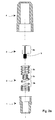
- Figure 2a
- represents a favourable embodiment of the invention as an exploded
diagram,
- Figure 2b
- shows the embodiment in Figure 2a assembled,
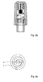
- Figure 2c
- shows the antenna elements of Figures 2a and 2b viewed from
another direction,
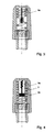
- Figure 3
- represents a second favourable embodiment of the invention,
- Figure 4
- represents a third favourable embodiment of the invention,
- Figure 5
- represents a fourth favourable embodiment of the invention.
In the description of the prior art above, reference is made to Figure 1, and so in the
following account of the invention and its favourable embodiments, reference will
chiefly be made to Figures 2a - 5. In the drawings, the same reference numbers are
employed for parts which correspond to one another.
Figure 2a is an exploded view, and parts 1, 2 and 4 show the antenna structure in
longitudinal section, where 1 is a connector, 2 is a helical element, 3 is an insulating
plate provided with a conductive pattern and 4 is a protective sheath made from an
insulation material. The structure is assembled by attaching helical element 2 to
connector 1 in a known manner, by pushing insulating plate 3 inside the helical
element and pressing protective sheath 4 onto the whole structure, thus forming an
antenna according to Figure 2b. The connector 1 is made from metal or another
electrically conductive material, and on the outside of the sleeve-like lower part
there is a screw thread for effective attachment of the antenna to the radio set (not
shown in the Figure). Figure 2c shows the combined helical element and insulating
plate viewed from above and from this it can be seen how the insulating plate 3 is
positioned inside the helical element 2.
On the surface of insulating plate 3 there is a conductive pattern 5, which on the
lower part of the plate extends to the edges of the plate and on the upper part of the
plate forms a straight conductor, so that it is possible to call it a whip element 5a.
When the plate is attached to the helical element in accordance with Figure 2b, the
lower part of the conductive pattern contacts at its edges the more tightly wound
portion in the middle of the helix, which is marked with reference number 2c. In
order to ensure electrical conductivity, the edges of the conductive pattern may be
soldered fast to the helical wire at point 2c. In an alternative embodiment, in which
galvanic contact between conductive pattern 5 and the helical element 2 is not
required, the conductive pattern does not need to extend to the edges of insulating
plate 3. In that case, the lower part of the whip element is connected to the junction
of the helical element capacitively. Below the junction there is a portion of the helix
marked with reference number 2a, and above the junction there is the portion of
helix marked with reference number 2b. The turns of the helix connected to the
connector 1 are not included in portion 2a, since the electrically conductive
connector short-circuits these turns and they do not act as a radiating part of the
antenna. The upper part of the insulating plate 3 may be wider than lower part
thereof, as in the Figure, in which case its edges support the upper part 2b of the
helix, or it may be of equal width, or of some other shape.
Typical design parameters for an antenna of this sort are the number of turns in the
lower part 2a and the upper part 2b of the helix and the position of the junction 2c to
which the conductive pattern 5 of specific length is connected. The dimensioning of
the helix (diameter of the helix and the number of turns in lower part 2a and the
number of turns in upper part 2b of the helix) determines the lower operating
frequency of the antenna. Helix 2 is so designed that it is, charged by whip element
5a, in tune with the lower operating frequency of the antenna, for example the GSM
or AMPS frequencies. The dimensioning of whip element 5a in proportion to junction
2c determines the upper operating frequency of the antenna, which is determined by
the proportion of the helix which is in its lower part 2a and by the length of the whip
element 5a. At the upper operating frequency the radiating antenna element is a
connection in series of the lower part 2a of the helix and the whip element.
The bandwidth of the operating frequencies is determined by the position of junction
2c or by the dimensional ratio of lower part 2a and upper part 2b of the helix. If the
junction 2c is shifted downwards in the helix or the number of turns in the lower part
2a of the helix is reduced, the bandwidth of the higher operating frequency
increases and the bandwidth of the lower operating frequency correspondingly
decreases. If the junction 2c is shifted upwards or the number of turns in the lower
part 2a of the helix increases in relation to the upper part 2b of the helix, the
bandwidth of the higher operating frequency decreases and the bandwidth of the
lower operating frequency increases. By means of the position of the junction 2c, by
the dimensioning of lower part 2a and upper part 2b of the helix and by selection of
the length of whip element 5a, the operating frequencies and bandwidths of the
antenna may be adjusted for desired system pairs. The selection of dimensions by
trial and error is in itself a technique known to those skilled in the art.
Figure 3 shows, in partial longitudinal section, a second favourable embodiment of
this invention, which differs from the embodiment shown in Figures 2a - 2c in that,
instead of being an insulating plate with a conductive pattern formed thereon, whip
element 5 is a straight piece of conductive filament. The junction 2c of the helix is
wound with a smaller diameter than in the embodiment shown in Figures 2a - 2c, so
that the whip element 5a may be pushed to the middle of the junction 2c. If the whip
element is thick enough and the diameter of the junction 2c is small enough, the
whip element may be attached in place simply by the effect of friction between it and
the helix wire. The connection may also be ensured by soldering, by adhesion or by
some other suitable procedure. If the whip element 5a is coated with an insulating
material, friction attachment or adhesion will be involved. In that case, electrical
connection between the helix and the whip element is capacitive. The insulation
coating may of course also be removed from below the whip element before
attachment, in which case the connection will be galvanic.
Figure 4 shows an embodiment of the invention in which the whip element 5a
formed on insulating plate 3 is not straight but forms a zig-zag pattern at the top.
Such a solution will be involved when the desired higher frequency of the antenna
necessitates such a great electrical length of the whip element that in the direction
of the longitudinal axis of the structure it would extend considerably further (upwards
in the drawing) than the helical element. Nothing of course prevents the whip
element from extending further than the helical element, but the structure will be
more compact if its length can be kept as small as possible. The helix in the
embodiment in Figure 4 does not have a junction with turns of smaller diameter, but
the insulating plate 3 is throughout as wide as the internal diameter of the helix, and
the whip element is connected capacitively via a widening 5b to the midpoint of the
helix.
Figure 5 is an exploded view in longitudinal section of the components of an
embodiment of this invention, in which the antenna element 6 designed for the
higher operating frequency is not a whip element but a helical element so small in
diameter that it fits into the upper part 2b of the larger helix. When the antenna
bends, however, the helices may strike each other, in which case functioning of the
antenna is disturbed This may be avoided by positioning around the smaller helix 6
a sleeve 7 made of an insulating material, the internal diameter of which is the same
as the external diameter of the smaller helix 6 and the external diameter of which is
the same as the internal diameter of the upper part 2b of the larger helix.
The above embodiments are intended only as examples, and it will clear to those
skilled in the art that the details of the embodiments of the invention may vary, and
thus realization of the invention lies within the scope of the patent claims below. The
present invention is not restricted to any specific application but may be employed in
antennae for different applications and at different frequencies, preferably at radio
frequencies, such as UHF and VHF. The structure is suitable for use for mobile
telephones.
The scope of the present disclosure includes any novel feature or combination of
features disclosed therein either explicitly or implicitly or any generalisation thereof
irrespective of whether or not it relates to the claimed invention or mitigates any or
all of the problems addressed by the present invention. The applicant hereby gives
notice that new claims may be formulated to such features during prosecution of this
application or of any such further application derived therefrom.