EP0826347A1 - Joint prosthesis - Google Patents
Joint prosthesis Download PDFInfo
- Publication number
- EP0826347A1 EP0826347A1 EP97113638A EP97113638A EP0826347A1 EP 0826347 A1 EP0826347 A1 EP 0826347A1 EP 97113638 A EP97113638 A EP 97113638A EP 97113638 A EP97113638 A EP 97113638A EP 0826347 A1 EP0826347 A1 EP 0826347A1
- Authority
- EP
- European Patent Office
- Prior art keywords
- insert
- carrier part
- clamping surface
- joint prosthesis
- angle
- Prior art date
- Legal status (The legal status is an assumption and is not a legal conclusion. Google has not performed a legal analysis and makes no representation as to the accuracy of the status listed.)
- Granted
Links
Images

Classifications
-
- A—HUMAN NECESSITIES
- A61—MEDICAL OR VETERINARY SCIENCE; HYGIENE
- A61F—FILTERS IMPLANTABLE INTO BLOOD VESSELS; PROSTHESES; DEVICES PROVIDING PATENCY TO, OR PREVENTING COLLAPSING OF, TUBULAR STRUCTURES OF THE BODY, e.g. STENTS; ORTHOPAEDIC, NURSING OR CONTRACEPTIVE DEVICES; FOMENTATION; TREATMENT OR PROTECTION OF EYES OR EARS; BANDAGES, DRESSINGS OR ABSORBENT PADS; FIRST-AID KITS
- A61F2/00—Filters implantable into blood vessels; Prostheses, i.e. artificial substitutes or replacements for parts of the body; Appliances for connecting them with the body; Devices providing patency to, or preventing collapsing of, tubular structures of the body, e.g. stents
- A61F2/02—Prostheses implantable into the body
- A61F2/30—Joints
- A61F2/46—Special tools or methods for implanting or extracting artificial joints, accessories, bone grafts or substitutes, or particular adaptations therefor
- A61F2/4637—Special tools or methods for implanting or extracting artificial joints, accessories, bone grafts or substitutes, or particular adaptations therefor for connecting or disconnecting two parts of a prosthesis
-
- A—HUMAN NECESSITIES
- A61—MEDICAL OR VETERINARY SCIENCE; HYGIENE
- A61F—FILTERS IMPLANTABLE INTO BLOOD VESSELS; PROSTHESES; DEVICES PROVIDING PATENCY TO, OR PREVENTING COLLAPSING OF, TUBULAR STRUCTURES OF THE BODY, e.g. STENTS; ORTHOPAEDIC, NURSING OR CONTRACEPTIVE DEVICES; FOMENTATION; TREATMENT OR PROTECTION OF EYES OR EARS; BANDAGES, DRESSINGS OR ABSORBENT PADS; FIRST-AID KITS
- A61F2/00—Filters implantable into blood vessels; Prostheses, i.e. artificial substitutes or replacements for parts of the body; Appliances for connecting them with the body; Devices providing patency to, or preventing collapsing of, tubular structures of the body, e.g. stents
- A61F2/02—Prostheses implantable into the body
- A61F2/30—Joints
- A61F2/32—Joints for the hip
- A61F2/34—Acetabular cups
-
- A—HUMAN NECESSITIES
- A61—MEDICAL OR VETERINARY SCIENCE; HYGIENE
- A61F—FILTERS IMPLANTABLE INTO BLOOD VESSELS; PROSTHESES; DEVICES PROVIDING PATENCY TO, OR PREVENTING COLLAPSING OF, TUBULAR STRUCTURES OF THE BODY, e.g. STENTS; ORTHOPAEDIC, NURSING OR CONTRACEPTIVE DEVICES; FOMENTATION; TREATMENT OR PROTECTION OF EYES OR EARS; BANDAGES, DRESSINGS OR ABSORBENT PADS; FIRST-AID KITS
- A61F2/00—Filters implantable into blood vessels; Prostheses, i.e. artificial substitutes or replacements for parts of the body; Appliances for connecting them with the body; Devices providing patency to, or preventing collapsing of, tubular structures of the body, e.g. stents
- A61F2/02—Prostheses implantable into the body
- A61F2/30—Joints
- A61F2/46—Special tools or methods for implanting or extracting artificial joints, accessories, bone grafts or substitutes, or particular adaptations therefor
- A61F2/4603—Special tools or methods for implanting or extracting artificial joints, accessories, bone grafts or substitutes, or particular adaptations therefor for insertion or extraction of endoprosthetic joints or of accessories thereof
- A61F2/4609—Special tools or methods for implanting or extracting artificial joints, accessories, bone grafts or substitutes, or particular adaptations therefor for insertion or extraction of endoprosthetic joints or of accessories thereof of acetabular cups
-
- A—HUMAN NECESSITIES
- A61—MEDICAL OR VETERINARY SCIENCE; HYGIENE
- A61F—FILTERS IMPLANTABLE INTO BLOOD VESSELS; PROSTHESES; DEVICES PROVIDING PATENCY TO, OR PREVENTING COLLAPSING OF, TUBULAR STRUCTURES OF THE BODY, e.g. STENTS; ORTHOPAEDIC, NURSING OR CONTRACEPTIVE DEVICES; FOMENTATION; TREATMENT OR PROTECTION OF EYES OR EARS; BANDAGES, DRESSINGS OR ABSORBENT PADS; FIRST-AID KITS
- A61F2/00—Filters implantable into blood vessels; Prostheses, i.e. artificial substitutes or replacements for parts of the body; Appliances for connecting them with the body; Devices providing patency to, or preventing collapsing of, tubular structures of the body, e.g. stents
- A61F2/02—Prostheses implantable into the body
- A61F2/30—Joints
- A61F2002/30001—Additional features of subject-matter classified in A61F2/28, A61F2/30 and subgroups thereof
- A61F2002/30316—The prosthesis having different structural features at different locations within the same prosthesis; Connections between prosthetic parts; Special structural features of bone or joint prostheses not otherwise provided for
- A61F2002/30317—The prosthesis having different structural features at different locations within the same prosthesis
- A61F2002/30321—The prosthesis having different structural features at different locations within the same prosthesis differing in roughness
-
- A—HUMAN NECESSITIES
- A61—MEDICAL OR VETERINARY SCIENCE; HYGIENE
- A61F—FILTERS IMPLANTABLE INTO BLOOD VESSELS; PROSTHESES; DEVICES PROVIDING PATENCY TO, OR PREVENTING COLLAPSING OF, TUBULAR STRUCTURES OF THE BODY, e.g. STENTS; ORTHOPAEDIC, NURSING OR CONTRACEPTIVE DEVICES; FOMENTATION; TREATMENT OR PROTECTION OF EYES OR EARS; BANDAGES, DRESSINGS OR ABSORBENT PADS; FIRST-AID KITS
- A61F2/00—Filters implantable into blood vessels; Prostheses, i.e. artificial substitutes or replacements for parts of the body; Appliances for connecting them with the body; Devices providing patency to, or preventing collapsing of, tubular structures of the body, e.g. stents
- A61F2/02—Prostheses implantable into the body
- A61F2/30—Joints
- A61F2002/30001—Additional features of subject-matter classified in A61F2/28, A61F2/30 and subgroups thereof
- A61F2002/30316—The prosthesis having different structural features at different locations within the same prosthesis; Connections between prosthetic parts; Special structural features of bone or joint prostheses not otherwise provided for
- A61F2002/30329—Connections or couplings between prosthetic parts, e.g. between modular parts; Connecting elements
- A61F2002/30331—Connections or couplings between prosthetic parts, e.g. between modular parts; Connecting elements made by longitudinally pushing a protrusion into a complementarily-shaped recess, e.g. held by friction fit
- A61F2002/30332—Conically- or frustoconically-shaped protrusion and recess
- A61F2002/30345—Multiple conical connection, i.e. the protrusion and recess having several tapered sections of different complementary conicities
-
- A—HUMAN NECESSITIES
- A61—MEDICAL OR VETERINARY SCIENCE; HYGIENE
- A61F—FILTERS IMPLANTABLE INTO BLOOD VESSELS; PROSTHESES; DEVICES PROVIDING PATENCY TO, OR PREVENTING COLLAPSING OF, TUBULAR STRUCTURES OF THE BODY, e.g. STENTS; ORTHOPAEDIC, NURSING OR CONTRACEPTIVE DEVICES; FOMENTATION; TREATMENT OR PROTECTION OF EYES OR EARS; BANDAGES, DRESSINGS OR ABSORBENT PADS; FIRST-AID KITS
- A61F2/00—Filters implantable into blood vessels; Prostheses, i.e. artificial substitutes or replacements for parts of the body; Appliances for connecting them with the body; Devices providing patency to, or preventing collapsing of, tubular structures of the body, e.g. stents
- A61F2/02—Prostheses implantable into the body
- A61F2/30—Joints
- A61F2002/30001—Additional features of subject-matter classified in A61F2/28, A61F2/30 and subgroups thereof
- A61F2002/30316—The prosthesis having different structural features at different locations within the same prosthesis; Connections between prosthetic parts; Special structural features of bone or joint prostheses not otherwise provided for
- A61F2002/30329—Connections or couplings between prosthetic parts, e.g. between modular parts; Connecting elements
- A61F2002/30331—Connections or couplings between prosthetic parts, e.g. between modular parts; Connecting elements made by longitudinally pushing a protrusion into a complementarily-shaped recess, e.g. held by friction fit
- A61F2002/30332—Conically- or frustoconically-shaped protrusion and recess
- A61F2002/30349—Conically- or frustoconically-shaped protrusion and recess the male and female complementary cones being of different conicities, i.e. for reducing the contact area
-
- A—HUMAN NECESSITIES
- A61—MEDICAL OR VETERINARY SCIENCE; HYGIENE
- A61F—FILTERS IMPLANTABLE INTO BLOOD VESSELS; PROSTHESES; DEVICES PROVIDING PATENCY TO, OR PREVENTING COLLAPSING OF, TUBULAR STRUCTURES OF THE BODY, e.g. STENTS; ORTHOPAEDIC, NURSING OR CONTRACEPTIVE DEVICES; FOMENTATION; TREATMENT OR PROTECTION OF EYES OR EARS; BANDAGES, DRESSINGS OR ABSORBENT PADS; FIRST-AID KITS
- A61F2/00—Filters implantable into blood vessels; Prostheses, i.e. artificial substitutes or replacements for parts of the body; Appliances for connecting them with the body; Devices providing patency to, or preventing collapsing of, tubular structures of the body, e.g. stents
- A61F2/02—Prostheses implantable into the body
- A61F2/30—Joints
- A61F2002/30001—Additional features of subject-matter classified in A61F2/28, A61F2/30 and subgroups thereof
- A61F2002/30316—The prosthesis having different structural features at different locations within the same prosthesis; Connections between prosthetic parts; Special structural features of bone or joint prostheses not otherwise provided for
- A61F2002/30535—Special structural features of bone or joint prostheses not otherwise provided for
- A61F2002/30593—Special structural features of bone or joint prostheses not otherwise provided for hollow
-
- A—HUMAN NECESSITIES
- A61—MEDICAL OR VETERINARY SCIENCE; HYGIENE
- A61F—FILTERS IMPLANTABLE INTO BLOOD VESSELS; PROSTHESES; DEVICES PROVIDING PATENCY TO, OR PREVENTING COLLAPSING OF, TUBULAR STRUCTURES OF THE BODY, e.g. STENTS; ORTHOPAEDIC, NURSING OR CONTRACEPTIVE DEVICES; FOMENTATION; TREATMENT OR PROTECTION OF EYES OR EARS; BANDAGES, DRESSINGS OR ABSORBENT PADS; FIRST-AID KITS
- A61F2/00—Filters implantable into blood vessels; Prostheses, i.e. artificial substitutes or replacements for parts of the body; Appliances for connecting them with the body; Devices providing patency to, or preventing collapsing of, tubular structures of the body, e.g. stents
- A61F2/02—Prostheses implantable into the body
- A61F2/30—Joints
- A61F2/30767—Special external or bone-contacting surface, e.g. coating for improving bone ingrowth
- A61F2/30771—Special external or bone-contacting surface, e.g. coating for improving bone ingrowth applied in original prostheses, e.g. holes or grooves
- A61F2002/3082—Grooves
-
- A—HUMAN NECESSITIES
- A61—MEDICAL OR VETERINARY SCIENCE; HYGIENE
- A61F—FILTERS IMPLANTABLE INTO BLOOD VESSELS; PROSTHESES; DEVICES PROVIDING PATENCY TO, OR PREVENTING COLLAPSING OF, TUBULAR STRUCTURES OF THE BODY, e.g. STENTS; ORTHOPAEDIC, NURSING OR CONTRACEPTIVE DEVICES; FOMENTATION; TREATMENT OR PROTECTION OF EYES OR EARS; BANDAGES, DRESSINGS OR ABSORBENT PADS; FIRST-AID KITS
- A61F2/00—Filters implantable into blood vessels; Prostheses, i.e. artificial substitutes or replacements for parts of the body; Appliances for connecting them with the body; Devices providing patency to, or preventing collapsing of, tubular structures of the body, e.g. stents
- A61F2/02—Prostheses implantable into the body
- A61F2/30—Joints
- A61F2/32—Joints for the hip
- A61F2002/3241—Joints for the hip having a ring, e.g. for locking the femoral head into the acetabular cup
-
- A—HUMAN NECESSITIES
- A61—MEDICAL OR VETERINARY SCIENCE; HYGIENE
- A61F—FILTERS IMPLANTABLE INTO BLOOD VESSELS; PROSTHESES; DEVICES PROVIDING PATENCY TO, OR PREVENTING COLLAPSING OF, TUBULAR STRUCTURES OF THE BODY, e.g. STENTS; ORTHOPAEDIC, NURSING OR CONTRACEPTIVE DEVICES; FOMENTATION; TREATMENT OR PROTECTION OF EYES OR EARS; BANDAGES, DRESSINGS OR ABSORBENT PADS; FIRST-AID KITS
- A61F2/00—Filters implantable into blood vessels; Prostheses, i.e. artificial substitutes or replacements for parts of the body; Appliances for connecting them with the body; Devices providing patency to, or preventing collapsing of, tubular structures of the body, e.g. stents
- A61F2/02—Prostheses implantable into the body
- A61F2/30—Joints
- A61F2/46—Special tools or methods for implanting or extracting artificial joints, accessories, bone grafts or substitutes, or particular adaptations therefor
- A61F2/4637—Special tools or methods for implanting or extracting artificial joints, accessories, bone grafts or substitutes, or particular adaptations therefor for connecting or disconnecting two parts of a prosthesis
- A61F2002/4641—Special tools or methods for implanting or extracting artificial joints, accessories, bone grafts or substitutes, or particular adaptations therefor for connecting or disconnecting two parts of a prosthesis for disconnecting
-
- A—HUMAN NECESSITIES
- A61—MEDICAL OR VETERINARY SCIENCE; HYGIENE
- A61F—FILTERS IMPLANTABLE INTO BLOOD VESSELS; PROSTHESES; DEVICES PROVIDING PATENCY TO, OR PREVENTING COLLAPSING OF, TUBULAR STRUCTURES OF THE BODY, e.g. STENTS; ORTHOPAEDIC, NURSING OR CONTRACEPTIVE DEVICES; FOMENTATION; TREATMENT OR PROTECTION OF EYES OR EARS; BANDAGES, DRESSINGS OR ABSORBENT PADS; FIRST-AID KITS
- A61F2220/00—Fixations or connections for prostheses classified in groups A61F2/00 - A61F2/26 or A61F2/82 or A61F9/00 or A61F11/00 or subgroups thereof
- A61F2220/0025—Connections or couplings between prosthetic parts, e.g. between modular parts; Connecting elements
- A61F2220/0033—Connections or couplings between prosthetic parts, e.g. between modular parts; Connecting elements made by longitudinally pushing a protrusion into a complementary-shaped recess, e.g. held by friction fit
-
- A—HUMAN NECESSITIES
- A61—MEDICAL OR VETERINARY SCIENCE; HYGIENE
- A61F—FILTERS IMPLANTABLE INTO BLOOD VESSELS; PROSTHESES; DEVICES PROVIDING PATENCY TO, OR PREVENTING COLLAPSING OF, TUBULAR STRUCTURES OF THE BODY, e.g. STENTS; ORTHOPAEDIC, NURSING OR CONTRACEPTIVE DEVICES; FOMENTATION; TREATMENT OR PROTECTION OF EYES OR EARS; BANDAGES, DRESSINGS OR ABSORBENT PADS; FIRST-AID KITS
- A61F2250/00—Special features of prostheses classified in groups A61F2/00 - A61F2/26 or A61F2/82 or A61F9/00 or A61F11/00 or subgroups thereof
- A61F2250/0014—Special features of prostheses classified in groups A61F2/00 - A61F2/26 or A61F2/82 or A61F9/00 or A61F11/00 or subgroups thereof having different values of a given property or geometrical feature, e.g. mechanical property or material property, at different locations within the same prosthesis
- A61F2250/0025—Special features of prostheses classified in groups A61F2/00 - A61F2/26 or A61F2/82 or A61F9/00 or A61F11/00 or subgroups thereof having different values of a given property or geometrical feature, e.g. mechanical property or material property, at different locations within the same prosthesis differing in roughness
-
- A—HUMAN NECESSITIES
- A61—MEDICAL OR VETERINARY SCIENCE; HYGIENE
- A61F—FILTERS IMPLANTABLE INTO BLOOD VESSELS; PROSTHESES; DEVICES PROVIDING PATENCY TO, OR PREVENTING COLLAPSING OF, TUBULAR STRUCTURES OF THE BODY, e.g. STENTS; ORTHOPAEDIC, NURSING OR CONTRACEPTIVE DEVICES; FOMENTATION; TREATMENT OR PROTECTION OF EYES OR EARS; BANDAGES, DRESSINGS OR ABSORBENT PADS; FIRST-AID KITS
- A61F2310/00—Prostheses classified in A61F2/28 or A61F2/30 - A61F2/44 being constructed from or coated with a particular material
- A61F2310/00005—The prosthesis being constructed from a particular material
- A61F2310/00011—Metals or alloys
-
- A—HUMAN NECESSITIES
- A61—MEDICAL OR VETERINARY SCIENCE; HYGIENE
- A61F—FILTERS IMPLANTABLE INTO BLOOD VESSELS; PROSTHESES; DEVICES PROVIDING PATENCY TO, OR PREVENTING COLLAPSING OF, TUBULAR STRUCTURES OF THE BODY, e.g. STENTS; ORTHOPAEDIC, NURSING OR CONTRACEPTIVE DEVICES; FOMENTATION; TREATMENT OR PROTECTION OF EYES OR EARS; BANDAGES, DRESSINGS OR ABSORBENT PADS; FIRST-AID KITS
- A61F2310/00—Prostheses classified in A61F2/28 or A61F2/30 - A61F2/44 being constructed from or coated with a particular material
- A61F2310/00005—The prosthesis being constructed from a particular material
- A61F2310/00179—Ceramics or ceramic-like structures
Definitions
- the present invention relates to a joint prosthesis with a pan-shaped support part in which a ceramic Use fixed by means of conical clamping is arranged.
- Joint prostheses which have a metallic support part and have an insert contained therein.
- the metallic support part is in the patient's bone anchored.
- the insert forms a wear-resistant one Sliding surface against which the joint ball of the bone or another prosthetic joint.
- the so-called hard sliding pairings exist at least Part of the articulation, for example the insert Metal.
- the attachment of the metallic insert in the carrier part also made of metal with the help of a polyethylene coupling.
- the polyethylene coupling is used through microrelative movements subject to wear. This wear is true not as serious as friction wear, nevertheless the seat of the insert is loosened and the abrasion gets into the tissue and the joint shell.
- US 5 282 864 describes a joint prosthesis where a metallic insert with the help of screws is anchored in a metallic support part.
- the Insert consists of a cobalt-chrome alloy, while the carrier part consists of a titanium alloy. Due to this structure of the joint prosthesis the risk of fretting and galvanic corrosion. In the event of corrosion, the metals give off toxic ions that can harm the patient.
- the invention has for its object the connection between the support part and the insert that a safe reproducible connection is achieved and at the same time removing the insert is possible.
- the ceramic Use by means of conical clamping in the pan-shaped Carrier part attached.
- the angle of the The clamping surface of the insert has a value other than the angle of the clamping surface of the carrier part, so that the Use only over a relatively small area with the Carrier part is connected. This enables a controlled Power transmission from the insert to the carrier part.
- the axially acting joint force is high used in extensive compressive stresses, minimizing the occurrence of tensile stress during use becomes.
- the load-bearing surface of the carrier part can be roughened so that, for example, a roughness of 20 ⁇ m is created. So irregularities in the Power transmission caused, for example, by deviations in shape arise in the micro range, be avoided.
- the Clamping surface of the carrier part finely turned or ground be so that the surface has a roughness from 0 to 4 ⁇ m.
- the insert preferably has that on the opening side opposite end of the clamping surface a radius or a slight additional slope. This will canting of the insert during insertion or during Put under load can be prevented. This can also be the case can be achieved in that on the opening side opposite end of the clamping surface of the carrier part an undercut follows.
- the insert If the insert wears out, it must be replaced will. To minimize the burden on the patient, the insert becomes in situ from the carrier part removed while it remains on the bone.
- a special one Embodiment of the invention at least one recess provided by the opening side on the Interface between insert and carrier part along to to the end of the two facing away from the opening side Clamping surfaces runs.
- the opening side opposite end of the recess is a Rocker arm that engages behind the clamping surface of the insert. With a tool such as one Wedge, the end of the recess located in the Rocker arm pressed against the insert, causing this is removed from the carrier part.
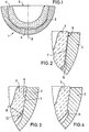
- Figure 1 shows a joint prosthesis 1 consisting of a pan-shaped metallic support part 2 and a die artificial joint-forming ceramic insert 3.
- the insert 3 is in an interior 4 of the carrier part 2 arranged.
- the inner surface of the insert 3 is formed as a ball socket on the opening side 5 takes up the counterpart of the joint.
- the mission 3 is by means of conical clamping in the carrier part 2 captured.
- the clamping surface 6 of the insert 3 runs under one Angle ⁇ to the clamping surface 7 of the carrier part 2 ( Figure 2).
- the angle at which the insert clamping surface 6 is too the joint axis 8 of the joint prosthesis is larger than the angle of the carrier part clamping surface 7.
- the size of the contact area 9 can by changing the angle ⁇ can be changed.
- the smaller the angle ⁇ the more the contact area 9 becomes larger.
- the angle ⁇ can also be negative.
- the contact surface is 9 in the lower area of the clamping surfaces 6 and 7. The one between the two contact surfaces 6 and 7 The gap thus opens towards the opening side 5.
- the clamping surface 7 of the carrier part 2 has one Roughness of about 20 ⁇ m. This will cause shape deviations the stake 3 balanced.
- FIG. 3 and 4 are the clamping surfaces 6 and 7 shown parallel to each other and not roughened, to improve clarity. Indeed the connection between insert 3 and the However, carrier part 2 as shown in Fig. 2.
- figure 3 connects to the lower end area of the clamping surface 6 of the insert 3 with a curved surface 10 the radius R.
- an undercut in the carrier part 2 11 is provided which in the region of the lower end of the Clamping surface 6 of the carrier part 3 is arranged (Fig. 4).
- the carrier part 2 has an elongated recess 12, which is in the border area located between the carrier part 2 and the insert 3 and parallel to the clamping surface 6 of the insert 3 runs.
- the recess 12 faces the opening side 5 the joint prosthesis 1 open.
- a rocker arm 13 which consists of two Legs 13a and 13b, which is under a flat Angles are arranged to each other.
- the leg 13a engages behind the clamping surface 6 of the insert 13 and is clamped between the insert 3 and the carrier part 2.
- the second leg 13b protrudes into the recess 12 in.
- the angle between the two legs 13a, 13b is designed so that the second leg 13b runs approximately parallel to the recess 12.
- FIG 6 it is shown how using a wedge-shaped Tool 14 of the rocker arm 13 is activated.
- the wedge 14 is pushed into the recess 12 until the wedge tip between the carrier part 2 and the second leg 13b of the rocker arm 13 is located.
- By further pressure on the wedge 14 becomes the second leg 13b pressed in the direction of the insert 3. This is causing also a movement of the first leg 13a, the pushes the insert 3 out of the carrier part 2.
Abstract
Description
Die vorliegende Erfindung betrifft eine Gelenkprothese mit einem pfannenförmigen Trägerteil, in dem ein keramischer Einsatz mittels konischer Klemmung festsitzend angeordnet ist.The present invention relates to a joint prosthesis with a pan-shaped support part in which a ceramic Use fixed by means of conical clamping is arranged.
Bekannt sind Gelenkprothesen, die ein metallisches Trägerteil und einen darin enthaltenen Einsatz aufweisen. Das metallische Trägerteil wird im Knochen des Patienten verankert. Der Einsatz bildet eine verschleißfeste Gleitfläche, gegen die die Gelenkkugel des Knochens oder einer anderen Gelenkprothese drückt. Bei den sogenannten harten Gleitpaarungen besteht zumindestens ein Teil der Gelenkverbindung, zum Beispiel der Einsatz aus Metall. Die Befestigung des metallischen Einsatzes in dem ebenfalls aus Metall bestehenden Trägerteil erfolgt mit Hilfe einer Polyethylen-Kupplung. Die Polyethylen-Kupplung ist durch Mikrorelativbewegungen zum Einsatz hin Verschleiß unterworfen. Dieser Verschleiß ist zwar nicht so gravierend wie Reibungsverschleiß, dennoch wird der Sitz des Einsatzes gelockert und der Abrieb gelangt in das Gewebe und die Gelenkschale.Joint prostheses are known which have a metallic support part and have an insert contained therein. The metallic support part is in the patient's bone anchored. The insert forms a wear-resistant one Sliding surface against which the joint ball of the bone or another prosthetic joint. With the so-called hard sliding pairings exist at least Part of the articulation, for example the insert Metal. The attachment of the metallic insert in the carrier part also made of metal with the help of a polyethylene coupling. The polyethylene coupling is used through microrelative movements subject to wear. This wear is true not as serious as friction wear, nevertheless the seat of the insert is loosened and the abrasion gets into the tissue and the joint shell.
In US 5 282 864 ist eine Gelenkprothese beschrieben, bei der ein metallischer Einsatz mit Hilfe von Schrauben in einem metallischen Tragerteil verankert ist. Der Einsatz besteht aus einer Kobalt-Chrom-Legierung, während das Trägerteil aus einer Titan-Legierung besteht. Bedingt durch diesen Aufbau der Gelenkprothese besteht die Gefahr von Reibkorrosion und galvanischer Korrosion. Bei Korrosion geben die Metalle toxische Ionen ab, die den Patienten schädigen können.US 5 282 864 describes a joint prosthesis where a metallic insert with the help of screws is anchored in a metallic support part. Of the Insert consists of a cobalt-chrome alloy, while the carrier part consists of a titanium alloy. Due to this structure of the joint prosthesis the risk of fretting and galvanic corrosion. In the event of corrosion, the metals give off toxic ions that can harm the patient.
Um diese Nachteile zu vermeiden, werden keramische Einsätze in die metallischen Trägerteile eingesetzt. Da keramische Werkstoffe nur schwer zu verarbeiten sind, werden sie meist mittels konischer Klemmung in dem Trägerteil befestigt. Ein Beispiel hierfür ist in EP 0 649 641 A2 beschrieben.To avoid these disadvantages, ceramic inserts inserted into the metallic support parts. There ceramic materials are difficult to process, they are mostly by means of conical clamping in the carrier part attached. An example of this is in EP 0 649 641 A2.
Bei der konischen Klemmung treten in bestimmten Zonen des Einsatzes erhebliche Zugspannungen auf, da die Krafteinleitung nicht kontrollierbar ist. Keramische Werkstoffe sind zwar sehr hart und druckfest, können aber nur begrenzt Zugkräfte aufnehmen. Dies führt dazu, daß insbesondere dünnwandige Keramikeinsätze technisch nicht realisiert werden können.Conical clamping occurs in certain zones use considerable tensile stresses because the Force transmission is not controllable. Ceramic Although materials are very hard and pressure-resistant, they can but only absorb tractive forces to a limited extent. This leads to, that in particular thin-walled ceramic inserts technically cannot be realized.
Der Erfindung liegt die Aufgabe zugrunde, die Verbindung zwischen dem Trägerteil und dem Einsatz so zu gestalten, daß eine sichere reproduzierbare Verbindung erreicht wird und gleichzeitig das Herauslösen des Einsatzes möglich ist. The invention has for its object the connection between the support part and the insert that a safe reproducible connection is achieved and at the same time removing the insert is possible.
Diese Aufgabe wird erfindungsgemäß durch die Merkmale
des Patentanspruchs 1 gelöst.This object is achieved by the features
of
Bei der erfindungsgemäßen Gelenkprothese wird der keramische Einsatz mittels konischer Klemmung in dem pfannenförmigen Trägerteil befestigt. Der Winkel der Klemmfläche des Einsatzes hat einen anderen Wert als der Winkel der Klemmfläche des Trägerteils, so daß der Einsatz nur über einen relativ kleinen Bereich mit dem Trägerteil verbunden ist. Dies ermöglicht eine kontrollierte Kraftübertragung von dem Einsatz auf das Trägerteil. Die axial wirkende Gelenkkraft wird in hohem Maß in umfänglich wirkende Druckspannungen eingesetzt, wobei das Entstehen von Zugspannungen im Einsatz minimiert wird.In the joint prosthesis according to the invention, the ceramic Use by means of conical clamping in the pan-shaped Carrier part attached. The angle of the The clamping surface of the insert has a value other than the angle of the clamping surface of the carrier part, so that the Use only over a relatively small area with the Carrier part is connected. This enables a controlled Power transmission from the insert to the carrier part. The axially acting joint force is high used in extensive compressive stresses, minimizing the occurrence of tensile stress during use becomes.
In einer bevorzugten Ausführung der Erfindung wird die Verbindung zwischen Trägerteil und Einsatz im Bereich der Öffnungsseite der Gelenkprothese realisiert. An dem der Öffnungsseite abgewandten Ende berühren sich die Klemmflächen nicht. Dies hat den Vorteil, daß die von der Gelenkprothese aufzunehmende Kraft gleichmäßig über den Umfang verteilt in einem bestimmten Bereich eingeleitet wird.In a preferred embodiment of the invention, the Connection between support part and use in the area the opening side of the joint prosthesis. To the the end facing away from the opening side touch No clamping surfaces. This has the advantage that the force to be absorbed evenly over the joint prosthesis the scope started in a certain area becomes.
Die lasttragende Oberfläche des Trägerteils kann aufgerauht werden, so daß zum Beispiel eine Rauhigkeit von 20 µm entsteht. So können Unregelmässigkeiten in der Kraftübertragung, die zum Beispiel durch Formabweichungen im Mikrobereich entstehen, vermieden werden.The load-bearing surface of the carrier part can be roughened so that, for example, a roughness of 20 µm is created. So irregularities in the Power transmission caused, for example, by deviations in shape arise in the micro range, be avoided.
Zur Verbesserung der Reibungseigenschaften kann die Klemmfläche des Trägerteils feinstgedreht oder geschliffen sein, so daß die Oberfläche eine Rauhigkeit von 0 bis 4 µm aufweist.To improve the friction properties, the Clamping surface of the carrier part finely turned or ground be so that the surface has a roughness from 0 to 4 µm.
Bevorzugterweise weist der Einsatz an dem der Öffnungsseite abgewandten Ende der Klemmfläche einen Radius oder eine leichte zusätzliche Schräge auf. Dadurch wird ein Verkanten des Einsatzes beim Einführen oder beim Setzen unter Last verhindert werden. Dies kann auch dadurch erreicht werden, daß sich an dem der Öffnungsseite abgewandten Ende der Klemmfläche des Trägerteils ein Freistich anschließt.The insert preferably has that on the opening side opposite end of the clamping surface a radius or a slight additional slope. This will canting of the insert during insertion or during Put under load can be prevented. This can also be the case can be achieved in that on the opening side opposite end of the clamping surface of the carrier part an undercut follows.
Bei Verschleiß des Einsatzes muß dieser ausgewechselt werden. Um die Belastung für den Patienten zu minimieren, wird der Einsatz in situ aus dem Trägerteil entfernt, während dieses am Knochen verbleibt. Um den Einsatz leicht entfernen zu können, ist in einer besonderen Ausgestaltung der Erfindung mindestens eine Ausnehmung vorgesehen, die von der Öffnungsseite an der Grenzfläche zwischen Einsatz und Trägerteil entlang bis zu dem der Öffnungsseite abgewandten Ende der beiden Klemmflächen verläuft. An dem inneren, der Öffnungsseite abgewandten Ende der Ausnehmung befindet sich ein Kipphebel, der die Klemmfläche des Einsatzes hintergreift. Mit einem Werkzeug, wie zum Beispiel einem Keil, kann das in der Ausnehmung befindliche Ende des Kipphebels gegen den Einsatz gedrückt werden, wodurch dieser aus dem Trägerteil entfernt wird.If the insert wears out, it must be replaced will. To minimize the burden on the patient, the insert becomes in situ from the carrier part removed while it remains on the bone. To the Being able to easily remove the insert is a special one Embodiment of the invention at least one recess provided by the opening side on the Interface between insert and carrier part along to to the end of the two facing away from the opening side Clamping surfaces runs. On the inside, the opening side opposite end of the recess is a Rocker arm that engages behind the clamping surface of the insert. With a tool such as one Wedge, the end of the recess located in the Rocker arm pressed against the insert, causing this is removed from the carrier part.
Im folgenden werden Ausführungsbeispiele der Erfindung unter Bezugnahme auf die Zeichnungen näher erläutert.The following are exemplary embodiments of the invention explained in more detail with reference to the drawings.
Es zeigen:
- Fig. 1
- einen Schnitt durch eine Gelenkprothese mit Trägerteil und einem darin festsitzenden Einsatz,
- Fig. 2
- eine Detaildarstellung der konischen Klemmung,
- Fig. 3
- eine Detaildarstellung des innengelegenen Endes der Klemmfläche des Einsatzes,
- Fig. 4
- eine Detaildarstellung des innengelegenen Endes der Klemmfläche des Trägerteils,
- Fig. 5
- eine Detaildarstellung der Gelenkprothese mit einer Ausnehmung und einem darin befindlichen Kipphebel zum Herauslösen des Einsatzes, und
- Fig. 6
- eine Detaildarstellung der Gelenkprothese mit einem den Kipphebel aktivierenden Werkzeug.
- Fig. 1
- a section through a joint prosthesis with support part and an insert stuck therein,
- Fig. 2
- a detailed representation of the conical clamping,
- Fig. 3
- a detailed representation of the inner end of the clamping surface of the insert,
- Fig. 4
- a detailed representation of the inner end of the clamping surface of the carrier part,
- Fig. 5
- a detailed view of the prosthetic joint with a recess and a rocker arm located therein for releasing the insert, and
- Fig. 6
- a detailed view of the joint prosthesis with a tool activating the rocker arm.
Figur 1 zeigt eine Gelenkprothese 1 bestehend aus einem
pfannenförmigen metallischen Trägerteil 2 und einem die
künstliche Gelenkschale bildenden keramischen Einsatz
3. Der Einsatz 3 ist in einem Innenraum 4 des Trägerteils
2 angeordnet. Die Innenfläche des Einsatzes 3 ist
als Kugelpfanne ausgebildet, die an der Öffnungsseite 5
das Gegenstück des Gelenkes aufnimmt. Der Einsatz 3
wird mittels konischer Klemmung in dem Trägerteil 2
festgehalten.Figure 1 shows a
Die Klemmfläche 6 des Einsatzes 3 verläuft unter einem
Winkel α zu der Klemmfläche 7 des Trägerteiles 2 (Figur
2). Der Winkel, unter dem die Einsatz-Klemmfläche 6 zu
der Gelenkachse 8 der Gelenkprothese verläuft, ist
größer als der Winkel der Trägerteil-Klemmfläche 7. The clamping
Dies bewirkt, daß der Einsatz 3 nur in einem relativ
kleinen Kontaktbereich 9, der sich an der Öffnungsseite
5 befindet, an das Trägerteil 2 gepreßt wird. Die Größe
des Kontaktbereiches 9 kann durch Änderung des Winkels
α verändert werden. Je kleiner der Winkel α ist, desto
größer wird der Kontaktbereich 9. Der Winkel α kann
auch negativ sein. In diesem Fall liegt die Kontaktfläche
9 im unteren Bereich der Klemmflächen 6 und 7.
Der zwischen den beiden Kontaktflächen 6 und 7 befindliche
Spalt öffnet sich also zur Öffnungsseite 5 hin.This causes the
Die Klemmfläche 7 des Trägerteiles 2 weist eine
Rauhigkeit von etwa 20 µm auf. Dadurch werden Formabweichungen
des Einsatzes 3 ausgeglichen.The clamping
In den Figuren 3 und 4 sind die Klemmflächen 6 und 7
parallel zueinander und nicht aufgerauht dargestellt,
um die Übersichtlichkeit zu verbessern. Tatsächlich
erfolgt die Verbindung zwischen dem Einsatz 3 und dem
Trägerteil 2 jedoch wie in Fig. 2 dargestellt. In Figur
3 schließt sich an den unteren Endbereich der Klemmfläche
6 des Einsatzes 3 eine gekrümmte Fläche 10 mit
dem Radius R an. Bei dem Einführen des Einsatzes 3 in
das Trägerteil 2 wird durch diese Abrundung der unteren
Kante der Klemmfläche 6 ein Verkanten des Einsatzes 3
in dem Trägerteil 2 vermieden. Dies kann auch dadurch
erreicht werden, daß in dem Trägerteil 2 ein Freistich
11 vorgesehen ist, der im Bereich des unteren Endes der
Klemmfläche 6 des Trägerteils 3 angeordnet ist (Fig.
4).3 and 4 are the clamping
In Figur 5 ist ein weiteres Ausführungsbeispiel der
Gelenkprothese 1 dargestellt. Das Trägerteil 2 weist
eine längliche Ausnehmung 12 auf, die sich im Grenzbereich
zwischen dem Trägerteil 2 und dem Einsatz 3 befindet
und parallel zu der Klemmfläche 6 des Einsatzes
3 verläuft. Die Ausnehmung 12 ist zur Öffnungsseite 5
der Gelenkprothese 1 offen. In dem unteren Ende der
Ausnehmung befindet sich ein Kipphebel 13, der aus zwei
Schenkeln 13a und 13b besteht, die unter einem flachen
Winkel zueinander angeordnet sind. Der Schenkel 13a
hintergreift die Klemmfläche 6 des Einsatzes 13 und
wird zwischen dem Einsatz 3 und dem Trägerteil 2 eingeklemmt.
Der zweite Schenkel 13b ragt in die Ausnehmung
12 hinein. Der Winkel zwischen den beiden Schenkeln
13a,13b ist so ausgelegt, daß der zweite Schenkel 13b
etwa parallel zu der Ausnehmung 12 verläuft.5 shows a further embodiment of the
In Figur 6 ist gezeigt, wie mit Hilfe eines keilförmigen
Werkzeuges 14 der Kipphebel 13 aktiviert wird.
Der Keil 14 wird in die Ausnehmung 12 geschoben, bis
die Keilspitze sich zwischen dem Trägerteil 2 und dem
zweiten Schenkel 13b des Kipphebels 13 befindet. Durch
weiteren Druck auf den Keil 14 wird der zweite Schenkel
13b in Richtung des Einsatzes 3 gedrückt. Dies verursacht
auch eine Bewegung des ersten Schenkels 13a, der
den Einsatz 3 aus dem Trägerteil 2 herausdrückt.In Figure 6 it is shown how using a wedge-shaped
Claims (10)
dadurch gekennzeichnet,
daß der Winkel der Klemmfläche (6) des Einsatzes (3) verschieden ist von dem Winkel der Klemmfläche (7) des Trägerteiles (2).Joint prosthesis with a cup-shaped support part (2), in the interior of which a ceramic insert (3) is arranged by means of conical clamping,
characterized,
that the angle of the clamping surface (6) of the insert (3) is different from the angle of the clamping surface (7) of the carrier part (2).
Applications Claiming Priority (4)
| Application Number | Priority Date | Filing Date | Title |
|---|---|---|---|
| DE19634274 | 1996-08-24 | ||
| DE19634274 | 1996-08-24 | ||
| DE19701536 | 1997-01-17 | ||
| DE19701536A DE19701536A1 (en) | 1996-08-24 | 1997-01-17 | Joint prosthesis |
Publications (2)
| Publication Number | Publication Date |
|---|---|
| EP0826347A1 true EP0826347A1 (en) | 1998-03-04 |
| EP0826347B1 EP0826347B1 (en) | 2002-12-11 |
Family
ID=26028712
Family Applications (1)
| Application Number | Title | Priority Date | Filing Date |
|---|---|---|---|
| EP97113638A Expired - Lifetime EP0826347B1 (en) | 1996-08-24 | 1997-08-07 | Joint prosthesis |
Country Status (4)
| Country | Link |
|---|---|
| US (1) | US5919236A (en) |
| EP (1) | EP0826347B1 (en) |
| AT (1) | ATE229307T1 (en) |
| ES (1) | ES2184017T3 (en) |
Cited By (8)
| Publication number | Priority date | Publication date | Assignee | Title |
|---|---|---|---|---|
| EP0995412A1 (en) * | 1998-10-23 | 2000-04-26 | Sulzer Orthopädie AG | Method for loosening an insert from the shell of an artificial joint cup and artificial joint cup |
| FR2798583A1 (en) * | 1999-09-21 | 2001-03-23 | Denis Chambaud | COTYLOIDIAN IMPLANT |
| US6358282B1 (en) | 1998-10-23 | 2002-03-19 | Sulzer Orthpaedie Ag | Method for the releasing of an insert from the shell of an artifical joint pan and artifical joint pan |
| EP1312323A3 (en) * | 2000-03-15 | 2005-08-24 | Depuy Orthopaedics, Inc. | Prosthetic cup assembly having increased assembly congruency |
| DE102011017809A1 (en) | 2010-07-16 | 2011-11-03 | Ceram Tec Gmbh | Acetabulum and cup insert combination for hip joint prosthesis, has cup insert coupled with acetabulum over expander cone, where tangential transitions occur between geometry elements of radial contour lines |
| WO2011135074A1 (en) | 2010-04-30 | 2011-11-03 | Ceramtec Gmbh | Increasing the breaking load of ceramic cup inserts for hip joint prostheses by a defined back side collision of the cup insert and acetabular cup |
| US8123815B2 (en) | 2008-11-24 | 2012-02-28 | Biomet Manufacturing Corp. | Multiple bearing acetabular prosthesis |
| US8308810B2 (en) | 2009-07-14 | 2012-11-13 | Biomet Manufacturing Corp. | Multiple bearing acetabular prosthesis |
Families Citing this family (31)
| Publication number | Priority date | Publication date | Assignee | Title |
|---|---|---|---|---|
| CA2420898A1 (en) * | 2000-08-28 | 2002-03-07 | Advanced Bio Surfaces, Inc. | Method for mammalian joint resurfacing |
| WO2002102285A1 (en) * | 2001-06-15 | 2002-12-27 | Permedica S.P.A. | Acetabular cup for hip joint prosthesis |
| EP1455692B1 (en) | 2001-12-04 | 2010-02-17 | Active Implants Corporation | Cushion bearing implants for load bearing applications |
| ES2323775T3 (en) | 2002-05-23 | 2009-07-24 | Active Implants Corporation | DENTAL AND ARTICULATION IMPLANTS. |
| US20060190089A1 (en) * | 2005-02-18 | 2006-08-24 | Howmedica Osteonics Corp. | Internal adaptor for hip acetabular cage |
| US7591853B2 (en) | 2005-03-09 | 2009-09-22 | Vertebral Technologies, Inc. | Rail-based modular disc nucleus prosthesis |
| US8454617B2 (en) | 2005-08-16 | 2013-06-04 | Benvenue Medical, Inc. | Devices for treating the spine |
| US20070106392A1 (en) * | 2005-11-08 | 2007-05-10 | Howmedica Osteonics Corp. | Acetabular cup locking mechanism |
| US8679187B2 (en) | 2006-03-20 | 2014-03-25 | Smith & Nephew, Inc. | Acetabular cup assembly for multiple bearing materials |
| US20080071379A1 (en) * | 2006-05-10 | 2008-03-20 | Mark Rydell | Intervertebral disc replacement |
| US9737414B2 (en) | 2006-11-21 | 2017-08-22 | Vertebral Technologies, Inc. | Methods and apparatus for minimally invasive modular interbody fusion devices |
| US8328873B2 (en) | 2007-01-10 | 2012-12-11 | Biomet Manufacturing Corp. | Knee joint prosthesis system and method for implantation |
| US8157869B2 (en) | 2007-01-10 | 2012-04-17 | Biomet Manufacturing Corp. | Knee joint prosthesis system and method for implantation |
| US8187280B2 (en) | 2007-10-10 | 2012-05-29 | Biomet Manufacturing Corp. | Knee joint prosthesis system and method for implantation |
| US8562616B2 (en) | 2007-10-10 | 2013-10-22 | Biomet Manufacturing, Llc | Knee joint prosthesis system and method for implantation |
| US8163028B2 (en) | 2007-01-10 | 2012-04-24 | Biomet Manufacturing Corp. | Knee joint prosthesis system and method for implantation |
| US20080281428A1 (en) * | 2007-05-07 | 2008-11-13 | Zimmer, Inc. | Methods and apparatuses for attaching soft tissue to orthopaedic implants |
| US7780740B2 (en) * | 2007-05-21 | 2010-08-24 | Active Implants Corporation | Methods, systems, and apparatus for implanting prosthetic devices into cartilage |
| EP2008619B1 (en) * | 2007-06-26 | 2016-11-02 | Finsbury (Development) Limited | Prosthesis |
| EP2008620A3 (en) * | 2007-06-26 | 2009-08-19 | Finsbury (Development) Limited | Prosthesis |
| US9364338B2 (en) | 2008-07-23 | 2016-06-14 | Resspond Spinal Systems | Modular nucleus pulposus prosthesis |
| CA2731048C (en) * | 2008-07-23 | 2016-11-29 | Marc I. Malberg | Modular nucleus pulposus prosthesis |
| FR2935262B1 (en) | 2008-09-01 | 2010-09-10 | Denis Pichon | JOINT PROTHETIC COTYLE. |
| FR2935263B1 (en) * | 2008-09-01 | 2012-02-24 | Denis Pichon | JOINT PROTHETIC COTYLE. |
| AU2012227336B2 (en) * | 2011-09-30 | 2015-03-26 | Depuy Products, Inc. | Self-centering, anti-seizing acetabular liner |
| US8771367B2 (en) | 2011-09-30 | 2014-07-08 | DePuy Synthes Products, LLC | Self centering, anti-seizing acetabular liner |
| US9510953B2 (en) | 2012-03-16 | 2016-12-06 | Vertebral Technologies, Inc. | Modular segmented disc nucleus implant |
| GB2529203B (en) * | 2014-08-13 | 2016-09-28 | James Wallace Mcminn Derek | Acetabular cup prosthesis |
| RU2018122094A (en) * | 2015-11-19 | 2019-12-19 | Керамтек Гмбх | RING CERAMIC INSERT FOR ENDOPROSTHESIS |
| US10507114B2 (en) | 2016-05-09 | 2019-12-17 | Alessandro MELOZZI | Universal prosthetic head for hip prosthesis |
| US10307255B1 (en) | 2017-11-29 | 2019-06-04 | b-ONE Ortho, Corp. | Acetabular cup assembly |
Citations (13)
| Publication number | Priority date | Publication date | Assignee | Title |
|---|---|---|---|---|
| FR2329249A1 (en) * | 1975-10-27 | 1977-05-27 | Sulzer Ag | JOINT PROSTHESIS |
| EP0237751A1 (en) * | 1986-02-18 | 1987-09-23 | GebràDer Sulzer Aktiengesellschaft | Endoprosthesis for an acetabular cup |
| EP0445068A1 (en) * | 1990-03-02 | 1991-09-04 | Gebrüder Sulzer Aktiengesellschaft | Artificial hip cup |
| EP0444381A1 (en) * | 1990-03-01 | 1991-09-04 | GebràDer Sulzer Aktiengesellschaft | Metal hip socket which can be fitted without cement |
| US5282864A (en) | 1992-02-19 | 1994-02-01 | Joint Medical Products Corporation | Acetabular prosthesis having a metal socket bearing |
| EP0586335A1 (en) * | 1992-09-02 | 1994-03-09 | SULZER Medizinaltechnik AG | Two-piece acetabular cup |
| WO1994023670A1 (en) * | 1993-04-22 | 1994-10-27 | Implex Corporation | Prosthetic acetabular cup and method of implant |
| EP0640324A1 (en) * | 1993-08-30 | 1995-03-01 | SULZER Medizinaltechnik AG | Artificial acetubular cup |
| EP0649641A2 (en) | 1993-10-21 | 1995-04-26 | CERASIV GmbH INNOVATIVES KERAMIK-ENGINEERING | Conical hip joint acetabular cup |
| US5413610A (en) * | 1986-12-25 | 1995-05-09 | Kyocera Corporation | Artificial hip joint |
| DE4337936A1 (en) * | 1993-11-06 | 1995-05-11 | Cerasiv Gmbh | Spherical acetabular cup |
| EP0655230A1 (en) * | 1993-11-26 | 1995-05-31 | CERASIV GmbH INNOVATIVES KERAMIK-ENGINEERING | Conical acetabular cup without any self-blocking |
| EP0694294A1 (en) * | 1994-07-28 | 1996-01-31 | Werner Hermann | Socket of a joint prosthesis |
Family Cites Families (7)
| Publication number | Priority date | Publication date | Assignee | Title |
|---|---|---|---|---|
| US4012795A (en) * | 1974-10-29 | 1977-03-22 | Feldmuhle Anlagen- Und Produktionsgesellschaft Mit Beschrankter Haftung | Artificial head assembly for an articulated joint between two bones |
| CH661430A5 (en) * | 1983-12-12 | 1987-07-31 | Sulzer Ag | Hip joint socket. |
| FR2633179B1 (en) * | 1988-06-28 | 1992-03-27 | Desmarquest Ceramiques Tech | IMPROVED ASSEMBLY OF A CERAMIC HEAD ON A METAL ROD FOR HIP PROSTHESIS |
| US5362311A (en) * | 1990-01-05 | 1994-11-08 | Kyocera Corporation | Artificial hip joint |
| US5314487A (en) * | 1991-02-14 | 1994-05-24 | Smith & Nephew Richards Inc. | Acetabular prosthesis with anchoring pegs |
| US5405392A (en) * | 1992-06-10 | 1995-04-11 | Deckner; Andre G. | Articular prosthetic device |
| US5549703A (en) * | 1995-02-16 | 1996-08-27 | Smith & Nephew Richards Inc. | Orthopedic prosthesis apparatus with improved taper locking connection |
-
1997
- 1997-08-07 ES ES97113638T patent/ES2184017T3/en not_active Expired - Lifetime
- 1997-08-07 EP EP97113638A patent/EP0826347B1/en not_active Expired - Lifetime
- 1997-08-07 AT AT97113638T patent/ATE229307T1/en active
- 1997-08-22 US US08/916,670 patent/US5919236A/en not_active Expired - Lifetime
Patent Citations (13)
| Publication number | Priority date | Publication date | Assignee | Title |
|---|---|---|---|---|
| FR2329249A1 (en) * | 1975-10-27 | 1977-05-27 | Sulzer Ag | JOINT PROSTHESIS |
| EP0237751A1 (en) * | 1986-02-18 | 1987-09-23 | GebràDer Sulzer Aktiengesellschaft | Endoprosthesis for an acetabular cup |
| US5413610A (en) * | 1986-12-25 | 1995-05-09 | Kyocera Corporation | Artificial hip joint |
| EP0444381A1 (en) * | 1990-03-01 | 1991-09-04 | GebràDer Sulzer Aktiengesellschaft | Metal hip socket which can be fitted without cement |
| EP0445068A1 (en) * | 1990-03-02 | 1991-09-04 | Gebrüder Sulzer Aktiengesellschaft | Artificial hip cup |
| US5282864A (en) | 1992-02-19 | 1994-02-01 | Joint Medical Products Corporation | Acetabular prosthesis having a metal socket bearing |
| EP0586335A1 (en) * | 1992-09-02 | 1994-03-09 | SULZER Medizinaltechnik AG | Two-piece acetabular cup |
| WO1994023670A1 (en) * | 1993-04-22 | 1994-10-27 | Implex Corporation | Prosthetic acetabular cup and method of implant |
| EP0640324A1 (en) * | 1993-08-30 | 1995-03-01 | SULZER Medizinaltechnik AG | Artificial acetubular cup |
| EP0649641A2 (en) | 1993-10-21 | 1995-04-26 | CERASIV GmbH INNOVATIVES KERAMIK-ENGINEERING | Conical hip joint acetabular cup |
| DE4337936A1 (en) * | 1993-11-06 | 1995-05-11 | Cerasiv Gmbh | Spherical acetabular cup |
| EP0655230A1 (en) * | 1993-11-26 | 1995-05-31 | CERASIV GmbH INNOVATIVES KERAMIK-ENGINEERING | Conical acetabular cup without any self-blocking |
| EP0694294A1 (en) * | 1994-07-28 | 1996-01-31 | Werner Hermann | Socket of a joint prosthesis |
Cited By (13)
| Publication number | Priority date | Publication date | Assignee | Title |
|---|---|---|---|---|
| US6358282B1 (en) | 1998-10-23 | 2002-03-19 | Sulzer Orthpaedie Ag | Method for the releasing of an insert from the shell of an artifical joint pan and artifical joint pan |
| EP0995412A1 (en) * | 1998-10-23 | 2000-04-26 | Sulzer Orthopädie AG | Method for loosening an insert from the shell of an artificial joint cup and artificial joint cup |
| FR2798583A1 (en) * | 1999-09-21 | 2001-03-23 | Denis Chambaud | COTYLOIDIAN IMPLANT |
| EP1086666A1 (en) * | 1999-09-21 | 2001-03-28 | Denis Chambaud | Cotyloidal implant |
| EP1312323A3 (en) * | 2000-03-15 | 2005-08-24 | Depuy Orthopaedics, Inc. | Prosthetic cup assembly having increased assembly congruency |
| US7326253B2 (en) | 2001-11-16 | 2008-02-05 | Depuy Products, Inc. | Prosthetic cup assembly having increased assembly congruency |
| US8123815B2 (en) | 2008-11-24 | 2012-02-28 | Biomet Manufacturing Corp. | Multiple bearing acetabular prosthesis |
| US9445903B2 (en) | 2008-11-24 | 2016-09-20 | Biomet Manufacturing, Llc | Multi-bearing acetabular prosthesis |
| US8308810B2 (en) | 2009-07-14 | 2012-11-13 | Biomet Manufacturing Corp. | Multiple bearing acetabular prosthesis |
| US9445904B2 (en) | 2009-07-14 | 2016-09-20 | Biomet Manufacturing, Llc | Multiple bearing acetabular prosthesis |
| WO2011135074A1 (en) | 2010-04-30 | 2011-11-03 | Ceramtec Gmbh | Increasing the breaking load of ceramic cup inserts for hip joint prostheses by a defined back side collision of the cup insert and acetabular cup |
| US9820854B2 (en) | 2010-04-30 | 2017-11-21 | Ceramtec Gmbh | Increasing the breaking load of ceramic cup inserts for hip joint prostheses by a defined back side collision of the cup insert and acetabular cup |
| DE102011017809A1 (en) | 2010-07-16 | 2011-11-03 | Ceram Tec Gmbh | Acetabulum and cup insert combination for hip joint prosthesis, has cup insert coupled with acetabulum over expander cone, where tangential transitions occur between geometry elements of radial contour lines |
Also Published As
| Publication number | Publication date |
|---|---|
| ATE229307T1 (en) | 2002-12-15 |
| EP0826347B1 (en) | 2002-12-11 |
| ES2184017T3 (en) | 2003-04-01 |
| US5919236A (en) | 1999-07-06 |
Similar Documents
| Publication | Publication Date | Title |
|---|---|---|
| EP0826347B1 (en) | Joint prosthesis | |
| EP0655230B1 (en) | Conical acetabular cup without any self-blocking | |
| DE10065398C2 (en) | Length-adjustable placeholder for insertion between two vertebrae | |
| EP0861058B1 (en) | Acetabular prosthesis and surgical instrument for insertion thereof | |
| DE4435497C1 (en) | Modular bone implant with socket | |
| DE60033876T2 (en) | Modular tibial insert for a prosthetic system | |
| EP0547354A1 (en) | Adjustable hip joint endoprothesis | |
| DE2712855C2 (en) | Joint endoprosthesis | |
| DE2605180B2 (en) | Endo apparatus for articulated support of a shoulder or hip joint for the regeneration of bone and cartilage tissue in the joint elements | |
| EP0876807A1 (en) | Adaptive shaft interconnector between a stump harness and the body of a prosthesis | |
| DE19701536A1 (en) | Joint prosthesis | |
| EP1028831A1 (en) | Actuating tool | |
| EP0743049A1 (en) | Artificial acetabular cup | |
| EP1098611B1 (en) | Cotyloid cavity prosthesis | |
| EP0024442A1 (en) | Composite endoprosthesis consisting of a metallic body and a ceramic joint | |
| DE69823968T2 (en) | Method for producing a cold-cured connector for modular parts | |
| DE2349357A1 (en) | PAN FASTENING A SPHERICAL JOINT PAN MADE OF A CERAMIC MATERIAL | |
| DE10261200A1 (en) | Stump cutting tool for a stump cutting device has shaft of cutting insert unit with at least one narrowed sector and one widened sector | |
| DE19654409C5 (en) | acetabulum | |
| DE8510531U1 (en) | Implant | |
| EP0307654B1 (en) | Implant as a substitute for a surgically removed patella part | |
| EP1728489B1 (en) | Hip endoprosthesis with acetabular having sealed bores | |
| WO1996022746A1 (en) | Modular bone implant with socket and pins | |
| EP1059070A2 (en) | Prosthesis shaft | |
| EP0205132B1 (en) | Cup for an artificial hip joint |
Legal Events
| Date | Code | Title | Description |
|---|---|---|---|
| PUAI | Public reference made under article 153(3) epc to a published international application that has entered the european phase |
Free format text: ORIGINAL CODE: 0009012 |
|
| AK | Designated contracting states |
Kind code of ref document: A1 Designated state(s): AT CH DE ES FR GB IT LI |
|
| 17P | Request for examination filed |
Effective date: 19980813 |
|
| AKX | Designation fees paid |
Free format text: AT CH DE ES FR GB IT LI |
|
| RBV | Designated contracting states (corrected) |
Designated state(s): AT CH DE ES FR GB IT LI |
|
| 17Q | First examination report despatched |
Effective date: 20010115 |
|
| GRAG | Despatch of communication of intention to grant |
Free format text: ORIGINAL CODE: EPIDOS AGRA |
|
| GRAG | Despatch of communication of intention to grant |
Free format text: ORIGINAL CODE: EPIDOS AGRA |
|
| GRAH | Despatch of communication of intention to grant a patent |
Free format text: ORIGINAL CODE: EPIDOS IGRA |
|
| GRAH | Despatch of communication of intention to grant a patent |
Free format text: ORIGINAL CODE: EPIDOS IGRA |
|
| GRAA | (expected) grant |
Free format text: ORIGINAL CODE: 0009210 |
|
| AK | Designated contracting states |
Kind code of ref document: B1 Designated state(s): AT CH DE ES FR GB IT LI |
|
| REF | Corresponds to: |
Ref document number: 229307 Country of ref document: AT Date of ref document: 20021215 Kind code of ref document: T |
|
| REG | Reference to a national code |
Ref country code: GB Ref legal event code: FG4D Free format text: NOT ENGLISH |
|
| REG | Reference to a national code |
Ref country code: CH Ref legal event code: EP |
|
| GBT | Gb: translation of ep patent filed (gb section 77(6)(a)/1977) |
Effective date: 20021211 |
|
| REG | Reference to a national code |
Ref country code: CH Ref legal event code: NV Representative=s name: ISLER & PEDRAZZINI AG |
|
| REF | Corresponds to: |
Ref document number: 59708928 Country of ref document: DE Date of ref document: 20030123 |
|
| REG | Reference to a national code |
Ref country code: ES Ref legal event code: FG2A Ref document number: 2184017 Country of ref document: ES Kind code of ref document: T3 |
|
| ET | Fr: translation filed | ||
| PLBE | No opposition filed within time limit |
Free format text: ORIGINAL CODE: 0009261 |
|
| STAA | Information on the status of an ep patent application or granted ep patent |
Free format text: STATUS: NO OPPOSITION FILED WITHIN TIME LIMIT |
|
| 26N | No opposition filed |
Effective date: 20030912 |
|
| REG | Reference to a national code |
Ref country code: CH Ref legal event code: PCAR Free format text: ISLER & PEDRAZZINI AG;POSTFACH 1772;8027 ZUERICH (CH) |
|
| REG | Reference to a national code |
Ref country code: FR Ref legal event code: PLFP Year of fee payment: 20 |
|
| PGFP | Annual fee paid to national office [announced via postgrant information from national office to epo] |
Ref country code: GB Payment date: 20160819 Year of fee payment: 20 Ref country code: CH Payment date: 20160819 Year of fee payment: 20 Ref country code: IT Payment date: 20160825 Year of fee payment: 20 |
|
| PGFP | Annual fee paid to national office [announced via postgrant information from national office to epo] |
Ref country code: AT Payment date: 20160822 Year of fee payment: 20 Ref country code: FR Payment date: 20160822 Year of fee payment: 20 |
|
| PGFP | Annual fee paid to national office [announced via postgrant information from national office to epo] |
Ref country code: ES Payment date: 20160810 Year of fee payment: 20 |
|
| PGFP | Annual fee paid to national office [announced via postgrant information from national office to epo] |
Ref country code: DE Payment date: 20161020 Year of fee payment: 20 |
|
| REG | Reference to a national code |
Ref country code: DE Ref legal event code: R071 Ref document number: 59708928 Country of ref document: DE |
|
| REG | Reference to a national code |
Ref country code: CH Ref legal event code: PL |
|
| REG | Reference to a national code |
Ref country code: GB Ref legal event code: PE20 Expiry date: 20170806 |
|
| REG | Reference to a national code |
Ref country code: AT Ref legal event code: MK07 Ref document number: 229307 Country of ref document: AT Kind code of ref document: T Effective date: 20170807 |
|
| PG25 | Lapsed in a contracting state [announced via postgrant information from national office to epo] |
Ref country code: GB Free format text: LAPSE BECAUSE OF EXPIRATION OF PROTECTION Effective date: 20170806 |
|
| REG | Reference to a national code |
Ref country code: ES Ref legal event code: FD2A Effective date: 20180508 |
|
| PG25 | Lapsed in a contracting state [announced via postgrant information from national office to epo] |
Ref country code: ES Free format text: LAPSE BECAUSE OF EXPIRATION OF PROTECTION Effective date: 20170808 |