EP0826347A1 - Gelenkprothese - Google Patents
Gelenkprothese Download PDFInfo
- Publication number
- EP0826347A1 EP0826347A1 EP97113638A EP97113638A EP0826347A1 EP 0826347 A1 EP0826347 A1 EP 0826347A1 EP 97113638 A EP97113638 A EP 97113638A EP 97113638 A EP97113638 A EP 97113638A EP 0826347 A1 EP0826347 A1 EP 0826347A1
- Authority
- EP
- European Patent Office
- Prior art keywords
- insert
- carrier part
- clamping surface
- joint prosthesis
- angle
- Prior art date
- Legal status (The legal status is an assumption and is not a legal conclusion. Google has not performed a legal analysis and makes no representation as to the accuracy of the status listed.)
- Granted
Links
Images

Classifications
-
- A—HUMAN NECESSITIES
- A61—MEDICAL OR VETERINARY SCIENCE; HYGIENE
- A61F—FILTERS IMPLANTABLE INTO BLOOD VESSELS; PROSTHESES; DEVICES PROVIDING PATENCY TO, OR PREVENTING COLLAPSING OF, TUBULAR STRUCTURES OF THE BODY, e.g. STENTS; ORTHOPAEDIC, NURSING OR CONTRACEPTIVE DEVICES; FOMENTATION; TREATMENT OR PROTECTION OF EYES OR EARS; BANDAGES, DRESSINGS OR ABSORBENT PADS; FIRST-AID KITS
- A61F2/00—Filters implantable into blood vessels; Prostheses, i.e. artificial substitutes or replacements for parts of the body; Appliances for connecting them with the body; Devices providing patency to, or preventing collapsing of, tubular structures of the body, e.g. stents
- A61F2/02—Prostheses implantable into the body
- A61F2/30—Joints
- A61F2/46—Special tools or methods for implanting or extracting artificial joints, accessories, bone grafts or substitutes, or particular adaptations therefor
- A61F2/4637—Special tools or methods for implanting or extracting artificial joints, accessories, bone grafts or substitutes, or particular adaptations therefor for connecting or disconnecting two parts of a prosthesis
-
- A—HUMAN NECESSITIES
- A61—MEDICAL OR VETERINARY SCIENCE; HYGIENE
- A61F—FILTERS IMPLANTABLE INTO BLOOD VESSELS; PROSTHESES; DEVICES PROVIDING PATENCY TO, OR PREVENTING COLLAPSING OF, TUBULAR STRUCTURES OF THE BODY, e.g. STENTS; ORTHOPAEDIC, NURSING OR CONTRACEPTIVE DEVICES; FOMENTATION; TREATMENT OR PROTECTION OF EYES OR EARS; BANDAGES, DRESSINGS OR ABSORBENT PADS; FIRST-AID KITS
- A61F2/00—Filters implantable into blood vessels; Prostheses, i.e. artificial substitutes or replacements for parts of the body; Appliances for connecting them with the body; Devices providing patency to, or preventing collapsing of, tubular structures of the body, e.g. stents
- A61F2/02—Prostheses implantable into the body
- A61F2/30—Joints
- A61F2/32—Joints for the hip
- A61F2/34—Acetabular cups
-
- A—HUMAN NECESSITIES
- A61—MEDICAL OR VETERINARY SCIENCE; HYGIENE
- A61F—FILTERS IMPLANTABLE INTO BLOOD VESSELS; PROSTHESES; DEVICES PROVIDING PATENCY TO, OR PREVENTING COLLAPSING OF, TUBULAR STRUCTURES OF THE BODY, e.g. STENTS; ORTHOPAEDIC, NURSING OR CONTRACEPTIVE DEVICES; FOMENTATION; TREATMENT OR PROTECTION OF EYES OR EARS; BANDAGES, DRESSINGS OR ABSORBENT PADS; FIRST-AID KITS
- A61F2/00—Filters implantable into blood vessels; Prostheses, i.e. artificial substitutes or replacements for parts of the body; Appliances for connecting them with the body; Devices providing patency to, or preventing collapsing of, tubular structures of the body, e.g. stents
- A61F2/02—Prostheses implantable into the body
- A61F2/30—Joints
- A61F2/46—Special tools or methods for implanting or extracting artificial joints, accessories, bone grafts or substitutes, or particular adaptations therefor
- A61F2/4603—Special tools or methods for implanting or extracting artificial joints, accessories, bone grafts or substitutes, or particular adaptations therefor for insertion or extraction of endoprosthetic joints or of accessories thereof
- A61F2/4609—Special tools or methods for implanting or extracting artificial joints, accessories, bone grafts or substitutes, or particular adaptations therefor for insertion or extraction of endoprosthetic joints or of accessories thereof of acetabular cups
-
- A—HUMAN NECESSITIES
- A61—MEDICAL OR VETERINARY SCIENCE; HYGIENE
- A61F—FILTERS IMPLANTABLE INTO BLOOD VESSELS; PROSTHESES; DEVICES PROVIDING PATENCY TO, OR PREVENTING COLLAPSING OF, TUBULAR STRUCTURES OF THE BODY, e.g. STENTS; ORTHOPAEDIC, NURSING OR CONTRACEPTIVE DEVICES; FOMENTATION; TREATMENT OR PROTECTION OF EYES OR EARS; BANDAGES, DRESSINGS OR ABSORBENT PADS; FIRST-AID KITS
- A61F2/00—Filters implantable into blood vessels; Prostheses, i.e. artificial substitutes or replacements for parts of the body; Appliances for connecting them with the body; Devices providing patency to, or preventing collapsing of, tubular structures of the body, e.g. stents
- A61F2/02—Prostheses implantable into the body
- A61F2/30—Joints
- A61F2002/30001—Additional features of subject-matter classified in A61F2/28, A61F2/30 and subgroups thereof
- A61F2002/30316—The prosthesis having different structural features at different locations within the same prosthesis; Connections between prosthetic parts; Special structural features of bone or joint prostheses not otherwise provided for
- A61F2002/30317—The prosthesis having different structural features at different locations within the same prosthesis
- A61F2002/30321—The prosthesis having different structural features at different locations within the same prosthesis differing in roughness
-
- A—HUMAN NECESSITIES
- A61—MEDICAL OR VETERINARY SCIENCE; HYGIENE
- A61F—FILTERS IMPLANTABLE INTO BLOOD VESSELS; PROSTHESES; DEVICES PROVIDING PATENCY TO, OR PREVENTING COLLAPSING OF, TUBULAR STRUCTURES OF THE BODY, e.g. STENTS; ORTHOPAEDIC, NURSING OR CONTRACEPTIVE DEVICES; FOMENTATION; TREATMENT OR PROTECTION OF EYES OR EARS; BANDAGES, DRESSINGS OR ABSORBENT PADS; FIRST-AID KITS
- A61F2/00—Filters implantable into blood vessels; Prostheses, i.e. artificial substitutes or replacements for parts of the body; Appliances for connecting them with the body; Devices providing patency to, or preventing collapsing of, tubular structures of the body, e.g. stents
- A61F2/02—Prostheses implantable into the body
- A61F2/30—Joints
- A61F2002/30001—Additional features of subject-matter classified in A61F2/28, A61F2/30 and subgroups thereof
- A61F2002/30316—The prosthesis having different structural features at different locations within the same prosthesis; Connections between prosthetic parts; Special structural features of bone or joint prostheses not otherwise provided for
- A61F2002/30329—Connections or couplings between prosthetic parts, e.g. between modular parts; Connecting elements
- A61F2002/30331—Connections or couplings between prosthetic parts, e.g. between modular parts; Connecting elements made by longitudinally pushing a protrusion into a complementarily-shaped recess, e.g. held by friction fit
- A61F2002/30332—Conically- or frustoconically-shaped protrusion and recess
- A61F2002/30345—Multiple conical connection, i.e. the protrusion and recess having several tapered sections of different complementary conicities
-
- A—HUMAN NECESSITIES
- A61—MEDICAL OR VETERINARY SCIENCE; HYGIENE
- A61F—FILTERS IMPLANTABLE INTO BLOOD VESSELS; PROSTHESES; DEVICES PROVIDING PATENCY TO, OR PREVENTING COLLAPSING OF, TUBULAR STRUCTURES OF THE BODY, e.g. STENTS; ORTHOPAEDIC, NURSING OR CONTRACEPTIVE DEVICES; FOMENTATION; TREATMENT OR PROTECTION OF EYES OR EARS; BANDAGES, DRESSINGS OR ABSORBENT PADS; FIRST-AID KITS
- A61F2/00—Filters implantable into blood vessels; Prostheses, i.e. artificial substitutes or replacements for parts of the body; Appliances for connecting them with the body; Devices providing patency to, or preventing collapsing of, tubular structures of the body, e.g. stents
- A61F2/02—Prostheses implantable into the body
- A61F2/30—Joints
- A61F2002/30001—Additional features of subject-matter classified in A61F2/28, A61F2/30 and subgroups thereof
- A61F2002/30316—The prosthesis having different structural features at different locations within the same prosthesis; Connections between prosthetic parts; Special structural features of bone or joint prostheses not otherwise provided for
- A61F2002/30329—Connections or couplings between prosthetic parts, e.g. between modular parts; Connecting elements
- A61F2002/30331—Connections or couplings between prosthetic parts, e.g. between modular parts; Connecting elements made by longitudinally pushing a protrusion into a complementarily-shaped recess, e.g. held by friction fit
- A61F2002/30332—Conically- or frustoconically-shaped protrusion and recess
- A61F2002/30349—Conically- or frustoconically-shaped protrusion and recess the male and female complementary cones being of different conicities, i.e. for reducing the contact area
-
- A—HUMAN NECESSITIES
- A61—MEDICAL OR VETERINARY SCIENCE; HYGIENE
- A61F—FILTERS IMPLANTABLE INTO BLOOD VESSELS; PROSTHESES; DEVICES PROVIDING PATENCY TO, OR PREVENTING COLLAPSING OF, TUBULAR STRUCTURES OF THE BODY, e.g. STENTS; ORTHOPAEDIC, NURSING OR CONTRACEPTIVE DEVICES; FOMENTATION; TREATMENT OR PROTECTION OF EYES OR EARS; BANDAGES, DRESSINGS OR ABSORBENT PADS; FIRST-AID KITS
- A61F2/00—Filters implantable into blood vessels; Prostheses, i.e. artificial substitutes or replacements for parts of the body; Appliances for connecting them with the body; Devices providing patency to, or preventing collapsing of, tubular structures of the body, e.g. stents
- A61F2/02—Prostheses implantable into the body
- A61F2/30—Joints
- A61F2002/30001—Additional features of subject-matter classified in A61F2/28, A61F2/30 and subgroups thereof
- A61F2002/30316—The prosthesis having different structural features at different locations within the same prosthesis; Connections between prosthetic parts; Special structural features of bone or joint prostheses not otherwise provided for
- A61F2002/30535—Special structural features of bone or joint prostheses not otherwise provided for
- A61F2002/30593—Special structural features of bone or joint prostheses not otherwise provided for hollow
-
- A—HUMAN NECESSITIES
- A61—MEDICAL OR VETERINARY SCIENCE; HYGIENE
- A61F—FILTERS IMPLANTABLE INTO BLOOD VESSELS; PROSTHESES; DEVICES PROVIDING PATENCY TO, OR PREVENTING COLLAPSING OF, TUBULAR STRUCTURES OF THE BODY, e.g. STENTS; ORTHOPAEDIC, NURSING OR CONTRACEPTIVE DEVICES; FOMENTATION; TREATMENT OR PROTECTION OF EYES OR EARS; BANDAGES, DRESSINGS OR ABSORBENT PADS; FIRST-AID KITS
- A61F2/00—Filters implantable into blood vessels; Prostheses, i.e. artificial substitutes or replacements for parts of the body; Appliances for connecting them with the body; Devices providing patency to, or preventing collapsing of, tubular structures of the body, e.g. stents
- A61F2/02—Prostheses implantable into the body
- A61F2/30—Joints
- A61F2/30767—Special external or bone-contacting surface, e.g. coating for improving bone ingrowth
- A61F2/30771—Special external or bone-contacting surface, e.g. coating for improving bone ingrowth applied in original prostheses, e.g. holes or grooves
- A61F2002/3082—Grooves
-
- A—HUMAN NECESSITIES
- A61—MEDICAL OR VETERINARY SCIENCE; HYGIENE
- A61F—FILTERS IMPLANTABLE INTO BLOOD VESSELS; PROSTHESES; DEVICES PROVIDING PATENCY TO, OR PREVENTING COLLAPSING OF, TUBULAR STRUCTURES OF THE BODY, e.g. STENTS; ORTHOPAEDIC, NURSING OR CONTRACEPTIVE DEVICES; FOMENTATION; TREATMENT OR PROTECTION OF EYES OR EARS; BANDAGES, DRESSINGS OR ABSORBENT PADS; FIRST-AID KITS
- A61F2/00—Filters implantable into blood vessels; Prostheses, i.e. artificial substitutes or replacements for parts of the body; Appliances for connecting them with the body; Devices providing patency to, or preventing collapsing of, tubular structures of the body, e.g. stents
- A61F2/02—Prostheses implantable into the body
- A61F2/30—Joints
- A61F2/32—Joints for the hip
- A61F2002/3241—Joints for the hip having a ring, e.g. for locking the femoral head into the acetabular cup
-
- A—HUMAN NECESSITIES
- A61—MEDICAL OR VETERINARY SCIENCE; HYGIENE
- A61F—FILTERS IMPLANTABLE INTO BLOOD VESSELS; PROSTHESES; DEVICES PROVIDING PATENCY TO, OR PREVENTING COLLAPSING OF, TUBULAR STRUCTURES OF THE BODY, e.g. STENTS; ORTHOPAEDIC, NURSING OR CONTRACEPTIVE DEVICES; FOMENTATION; TREATMENT OR PROTECTION OF EYES OR EARS; BANDAGES, DRESSINGS OR ABSORBENT PADS; FIRST-AID KITS
- A61F2/00—Filters implantable into blood vessels; Prostheses, i.e. artificial substitutes or replacements for parts of the body; Appliances for connecting them with the body; Devices providing patency to, or preventing collapsing of, tubular structures of the body, e.g. stents
- A61F2/02—Prostheses implantable into the body
- A61F2/30—Joints
- A61F2/46—Special tools or methods for implanting or extracting artificial joints, accessories, bone grafts or substitutes, or particular adaptations therefor
- A61F2/4637—Special tools or methods for implanting or extracting artificial joints, accessories, bone grafts or substitutes, or particular adaptations therefor for connecting or disconnecting two parts of a prosthesis
- A61F2002/4641—Special tools or methods for implanting or extracting artificial joints, accessories, bone grafts or substitutes, or particular adaptations therefor for connecting or disconnecting two parts of a prosthesis for disconnecting
-
- A—HUMAN NECESSITIES
- A61—MEDICAL OR VETERINARY SCIENCE; HYGIENE
- A61F—FILTERS IMPLANTABLE INTO BLOOD VESSELS; PROSTHESES; DEVICES PROVIDING PATENCY TO, OR PREVENTING COLLAPSING OF, TUBULAR STRUCTURES OF THE BODY, e.g. STENTS; ORTHOPAEDIC, NURSING OR CONTRACEPTIVE DEVICES; FOMENTATION; TREATMENT OR PROTECTION OF EYES OR EARS; BANDAGES, DRESSINGS OR ABSORBENT PADS; FIRST-AID KITS
- A61F2220/00—Fixations or connections for prostheses classified in groups A61F2/00 - A61F2/26 or A61F2/82 or A61F9/00 or A61F11/00 or subgroups thereof
- A61F2220/0025—Connections or couplings between prosthetic parts, e.g. between modular parts; Connecting elements
- A61F2220/0033—Connections or couplings between prosthetic parts, e.g. between modular parts; Connecting elements made by longitudinally pushing a protrusion into a complementary-shaped recess, e.g. held by friction fit
-
- A—HUMAN NECESSITIES
- A61—MEDICAL OR VETERINARY SCIENCE; HYGIENE
- A61F—FILTERS IMPLANTABLE INTO BLOOD VESSELS; PROSTHESES; DEVICES PROVIDING PATENCY TO, OR PREVENTING COLLAPSING OF, TUBULAR STRUCTURES OF THE BODY, e.g. STENTS; ORTHOPAEDIC, NURSING OR CONTRACEPTIVE DEVICES; FOMENTATION; TREATMENT OR PROTECTION OF EYES OR EARS; BANDAGES, DRESSINGS OR ABSORBENT PADS; FIRST-AID KITS
- A61F2250/00—Special features of prostheses classified in groups A61F2/00 - A61F2/26 or A61F2/82 or A61F9/00 or A61F11/00 or subgroups thereof
- A61F2250/0014—Special features of prostheses classified in groups A61F2/00 - A61F2/26 or A61F2/82 or A61F9/00 or A61F11/00 or subgroups thereof having different values of a given property or geometrical feature, e.g. mechanical property or material property, at different locations within the same prosthesis
- A61F2250/0025—Special features of prostheses classified in groups A61F2/00 - A61F2/26 or A61F2/82 or A61F9/00 or A61F11/00 or subgroups thereof having different values of a given property or geometrical feature, e.g. mechanical property or material property, at different locations within the same prosthesis differing in roughness
-
- A—HUMAN NECESSITIES
- A61—MEDICAL OR VETERINARY SCIENCE; HYGIENE
- A61F—FILTERS IMPLANTABLE INTO BLOOD VESSELS; PROSTHESES; DEVICES PROVIDING PATENCY TO, OR PREVENTING COLLAPSING OF, TUBULAR STRUCTURES OF THE BODY, e.g. STENTS; ORTHOPAEDIC, NURSING OR CONTRACEPTIVE DEVICES; FOMENTATION; TREATMENT OR PROTECTION OF EYES OR EARS; BANDAGES, DRESSINGS OR ABSORBENT PADS; FIRST-AID KITS
- A61F2310/00—Prostheses classified in A61F2/28 or A61F2/30 - A61F2/44 being constructed from or coated with a particular material
- A61F2310/00005—The prosthesis being constructed from a particular material
- A61F2310/00011—Metals or alloys
-
- A—HUMAN NECESSITIES
- A61—MEDICAL OR VETERINARY SCIENCE; HYGIENE
- A61F—FILTERS IMPLANTABLE INTO BLOOD VESSELS; PROSTHESES; DEVICES PROVIDING PATENCY TO, OR PREVENTING COLLAPSING OF, TUBULAR STRUCTURES OF THE BODY, e.g. STENTS; ORTHOPAEDIC, NURSING OR CONTRACEPTIVE DEVICES; FOMENTATION; TREATMENT OR PROTECTION OF EYES OR EARS; BANDAGES, DRESSINGS OR ABSORBENT PADS; FIRST-AID KITS
- A61F2310/00—Prostheses classified in A61F2/28 or A61F2/30 - A61F2/44 being constructed from or coated with a particular material
- A61F2310/00005—The prosthesis being constructed from a particular material
- A61F2310/00179—Ceramics or ceramic-like structures
Abstract
Description
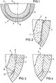
- Fig. 1
- einen Schnitt durch eine Gelenkprothese mit Trägerteil und einem darin festsitzenden Einsatz,
- Fig. 2
- eine Detaildarstellung der konischen Klemmung,
- Fig. 3
- eine Detaildarstellung des innengelegenen Endes der Klemmfläche des Einsatzes,
- Fig. 4
- eine Detaildarstellung des innengelegenen Endes der Klemmfläche des Trägerteils,
- Fig. 5
- eine Detaildarstellung der Gelenkprothese mit einer Ausnehmung und einem darin befindlichen Kipphebel zum Herauslösen des Einsatzes, und
- Fig. 6
- eine Detaildarstellung der Gelenkprothese mit einem den Kipphebel aktivierenden Werkzeug.
Claims (10)
- Gelenkprothese mit einem pfannenförmigen Trägerteil (2), in dessen Innenraum ein keramischer Einsatz (3) mittels konischer Klemmung festsitzend angeordnet ist,
dadurch gekennzeichnet,
daß der Winkel der Klemmfläche (6) des Einsatzes (3) verschieden ist von dem Winkel der Klemmfläche (7) des Trägerteiles (2). - Gelenkprothese nach Anspruch 1, dadurch gekennzeichnet, daß die Klemmfläche (6) des Einsatzes (7) unter einem Winkel (α) von 1 bis 20 Winkelminuten, bezogen auf die Klemmfläche (7) des Trägerteiles (2), verläuft, vorzugsweise unter einem Winkel (α) von 1 bis 5 Winkelminuten.
- Gelenkprothese nach Anspruch 2, dadurch gekennzeichnet, daß die Klemmfläche (6) des Einsatzes (3) im Bereich der Öffnungsseite (5) der Gelenkprothese an der Klemmfläche (7) des Trägerteiles (2) zur Erzeugung der konischen Klemmung anliegt.
- Gelenkprothese nach einem der Ansprüche 1 bis 3, dadurch gekennzeichnet, daß die Klemmfläche (7) des Trägerteiles (2) strukturiert ist.
- Gelenkprothese nach Anspruch 4, dadurch gekennzeichnet, daß die Klemmfläche (7) des Trägerteiles (2) eine Rauhigkeit von 20 µm aufweist.
- Gelenkprothese nach einem der Ansprüche 1 bis 3, dadurch gekennzeichnet, daß die Klemmfläche (7) des Trägerteiles (2) glatt ist.
- Gelenkprothese nach Anspruch 6, dadurch gekennzeichnet, daß die Klemmfläche (7) des Trägerteiles (2) eine Rauhigkeit von 0 bis 4 µm aufweist.
- Gelenkprothese nach einem der Ansprüche 1 bis 7, dadurch gekennzeichnet, daß der Einsatz (3) an dem Endbereich der konischen Klemmfläche (6) mit dem kleineren Durchmesser einen Radius (R) oder eine leichte zusätzliche Schräge (10) aufweist, die ein Verkanten beim Einsetzen des Einsatzes (3) in das Trägerteil (2) verhindert.
- Gelenkprothese nach einem der Ansprüche 1 bis 7, dadurch gekennzeichnet, daß das Trägerteil (2) an dem dem Innenraum (4) zugewandten Endbereich der Klemmfläche (7) einen Freistich (11) aufweist.
- Gelenkprothese nach einem der Ansprüche 1 bis 9, dadurch gekennzeichnet, daß in dem Trägerteil (2) auf der Klemmfläche (7) zumindestens eine Ausnehmung (12) von der Öffnungsseite (5) zu dem Innenraum (4) verläuft, daß am inneren Ende der Ausnehmung (12) ein die Klemmfläche (6) des Einsatzes (3) hintergreifender Kipphebel (13) angeordnet ist und daß zum Lösen des Einsatzes (3) aus dem Trägerteil (2) der Kipphebel (13) mit einem Werkzeug (14) umlegbar ist.
Applications Claiming Priority (4)
| Application Number | Priority Date | Filing Date | Title |
|---|---|---|---|
| DE19634274 | 1996-08-24 | ||
| DE19634274 | 1996-08-24 | ||
| DE19701536 | 1997-01-17 | ||
| DE19701536A DE19701536A1 (de) | 1996-08-24 | 1997-01-17 | Gelenkprothese |
Publications (2)
| Publication Number | Publication Date |
|---|---|
| EP0826347A1 true EP0826347A1 (de) | 1998-03-04 |
| EP0826347B1 EP0826347B1 (de) | 2002-12-11 |
Family
ID=26028712
Family Applications (1)
| Application Number | Title | Priority Date | Filing Date |
|---|---|---|---|
| EP97113638A Expired - Lifetime EP0826347B1 (de) | 1996-08-24 | 1997-08-07 | Gelenkprothese |
Country Status (4)
| Country | Link |
|---|---|
| US (1) | US5919236A (de) |
| EP (1) | EP0826347B1 (de) |
| AT (1) | ATE229307T1 (de) |
| ES (1) | ES2184017T3 (de) |
Cited By (8)
| Publication number | Priority date | Publication date | Assignee | Title |
|---|---|---|---|---|
| EP0995412A1 (de) * | 1998-10-23 | 2000-04-26 | Sulzer Orthopädie AG | Verfahren zum Lösen eines Einsatzes von der Schale einer künstlichen Gelenkpfanne und künstliche Gelenkpfanne |
| FR2798583A1 (fr) * | 1999-09-21 | 2001-03-23 | Denis Chambaud | Implant cotyloidien |
| US6358282B1 (en) | 1998-10-23 | 2002-03-19 | Sulzer Orthpaedie Ag | Method for the releasing of an insert from the shell of an artifical joint pan and artifical joint pan |
| EP1312323A3 (de) * | 2000-03-15 | 2005-08-24 | Depuy Orthopaedics, Inc. | Prosthetische Pfannenzusammensetzung mit zunehmender Zusammensetzungsübereinstimmung |
| DE102011017809A1 (de) | 2010-07-16 | 2011-11-03 | Ceram Tec Gmbh | Erhöhung der Bruchlast keramischer Pfanneneinsätze für Hüftgelenkprothesen durch definierte Rückseitenkollision von Pfanneneinsatz und Hüftpfanne |
| WO2011135074A1 (de) | 2010-04-30 | 2011-11-03 | Ceramtec Gmbh | Erhöhung der bruchlast keramischer pfanneneinsätze für hüftgelenkprothesen durch definierte rückseitenkollision von pfanneneinsatz und hüftpfanne |
| US8123815B2 (en) | 2008-11-24 | 2012-02-28 | Biomet Manufacturing Corp. | Multiple bearing acetabular prosthesis |
| US8308810B2 (en) | 2009-07-14 | 2012-11-13 | Biomet Manufacturing Corp. | Multiple bearing acetabular prosthesis |
Families Citing this family (31)
| Publication number | Priority date | Publication date | Assignee | Title |
|---|---|---|---|---|
| DE60139262D1 (de) * | 2000-08-28 | 2009-08-27 | Disc Dynamics Inc | System zur wiederherstellung von gelenkoberflächen von säugetieren |
| WO2002102285A1 (en) * | 2001-06-15 | 2002-12-27 | Permedica S.P.A. | Acetabular cup for hip joint prosthesis |
| DE60235400D1 (de) | 2001-12-04 | 2010-04-01 | Active Implants Corp | Kissenlagerungsimplantate für lasttragende anwendungen |
| WO2003099156A2 (en) | 2002-05-23 | 2003-12-04 | Discure, Ltd. | Joint and dental implants |
| US20060190089A1 (en) * | 2005-02-18 | 2006-08-24 | Howmedica Osteonics Corp. | Internal adaptor for hip acetabular cage |
| US7267690B2 (en) * | 2005-03-09 | 2007-09-11 | Vertebral Technologies, Inc. | Interlocked modular disc nucleus prosthesis |
| US20070106392A1 (en) * | 2005-11-08 | 2007-05-10 | Howmedica Osteonics Corp. | Acetabular cup locking mechanism |
| WO2007108848A1 (en) | 2006-03-20 | 2007-09-27 | Smith & Nephew, Inc. | Acetabular cup assembly for multiple bearing materials |
| US20080071379A1 (en) * | 2006-05-10 | 2008-03-20 | Mark Rydell | Intervertebral disc replacement |
| US9737414B2 (en) | 2006-11-21 | 2017-08-22 | Vertebral Technologies, Inc. | Methods and apparatus for minimally invasive modular interbody fusion devices |
| US8163028B2 (en) | 2007-01-10 | 2012-04-24 | Biomet Manufacturing Corp. | Knee joint prosthesis system and method for implantation |
| JP5448842B2 (ja) | 2007-01-10 | 2014-03-19 | バイオメト マニファクチャリング コーポレイション | 膝関節プロテーゼシステムおよび埋込み方法 |
| US8328873B2 (en) | 2007-01-10 | 2012-12-11 | Biomet Manufacturing Corp. | Knee joint prosthesis system and method for implantation |
| US8187280B2 (en) | 2007-10-10 | 2012-05-29 | Biomet Manufacturing Corp. | Knee joint prosthesis system and method for implantation |
| US8562616B2 (en) | 2007-10-10 | 2013-10-22 | Biomet Manufacturing, Llc | Knee joint prosthesis system and method for implantation |
| EP2124778B1 (de) | 2007-02-21 | 2019-09-25 | Benvenue Medical, Inc. | Vorrichtungen zur wirbelsäulenbehandlung |
| US20080281428A1 (en) * | 2007-05-07 | 2008-11-13 | Zimmer, Inc. | Methods and apparatuses for attaching soft tissue to orthopaedic implants |
| US7780740B2 (en) * | 2007-05-21 | 2010-08-24 | Active Implants Corporation | Methods, systems, and apparatus for implanting prosthetic devices into cartilage |
| EP2008619B1 (de) * | 2007-06-26 | 2016-11-02 | Finsbury (Development) Limited | Prothese |
| EP2008620A3 (de) * | 2007-06-26 | 2009-08-19 | Finsbury (Development) Limited | Prothese |
| US9364338B2 (en) | 2008-07-23 | 2016-06-14 | Resspond Spinal Systems | Modular nucleus pulposus prosthesis |
| KR101614561B1 (ko) * | 2008-07-23 | 2016-04-21 | 마르크 아이. 말베르크 | 모듈화된 수핵 보철기구 |
| FR2935263B1 (fr) * | 2008-09-01 | 2012-02-24 | Denis Pichon | Cotyle prothetique articulaire. |
| FR2935262B1 (fr) | 2008-09-01 | 2010-09-10 | Denis Pichon | Cotyle prothetique articulaire. |
| AU2012227336B2 (en) * | 2011-09-30 | 2015-03-26 | Depuy Products, Inc. | Self-centering, anti-seizing acetabular liner |
| US8771367B2 (en) | 2011-09-30 | 2014-07-08 | DePuy Synthes Products, LLC | Self centering, anti-seizing acetabular liner |
| US9510953B2 (en) | 2012-03-16 | 2016-12-06 | Vertebral Technologies, Inc. | Modular segmented disc nucleus implant |
| GB2529203B (en) * | 2014-08-13 | 2016-09-28 | James Wallace Mcminn Derek | Acetabular cup prosthesis |
| EP3377782B1 (de) * | 2015-11-19 | 2020-05-06 | CeramTec GmbH | Ringförmiges keramisches insert für die endoprothetik |
| US10507114B2 (en) | 2016-05-09 | 2019-12-17 | Alessandro MELOZZI | Universal prosthetic head for hip prosthesis |
| US10307255B1 (en) | 2017-11-29 | 2019-06-04 | b-ONE Ortho, Corp. | Acetabular cup assembly |
Citations (13)
| Publication number | Priority date | Publication date | Assignee | Title |
|---|---|---|---|---|
| FR2329249A1 (fr) * | 1975-10-27 | 1977-05-27 | Sulzer Ag | Prothese d'articulation |
| EP0237751A1 (de) * | 1986-02-18 | 1987-09-23 | GebràDer Sulzer Aktiengesellschaft | Endoprothese für eine Hüftgelenkspfanne |
| EP0444381A1 (de) * | 1990-03-01 | 1991-09-04 | GebràDer Sulzer Aktiengesellschaft | Zementfrei einzusetzende metallische Hüftgelenkspfanne |
| EP0445068A1 (de) * | 1990-03-02 | 1991-09-04 | Gebrüder Sulzer Aktiengesellschaft | Künstliche Hüftgelenkspfanne |
| US5282864A (en) | 1992-02-19 | 1994-02-01 | Joint Medical Products Corporation | Acetabular prosthesis having a metal socket bearing |
| EP0586335A1 (de) * | 1992-09-02 | 1994-03-09 | SULZER Medizinaltechnik AG | Zweiteilige Hüftgelenkpfanne |
| WO1994023670A1 (en) * | 1993-04-22 | 1994-10-27 | Implex Corporation | Prosthetic acetabular cup and method of implant |
| EP0640324A1 (de) * | 1993-08-30 | 1995-03-01 | SULZER Medizinaltechnik AG | Künstliche Hüftgelenkpfanne |
| EP0649641A2 (de) | 1993-10-21 | 1995-04-26 | CERASIV GmbH INNOVATIVES KERAMIK-ENGINEERING | Konische Hüftgelenkpfanne |
| US5413610A (en) * | 1986-12-25 | 1995-05-09 | Kyocera Corporation | Artificial hip joint |
| DE4337936A1 (de) * | 1993-11-06 | 1995-05-11 | Cerasiv Gmbh | Sphärische Hüftgelenkpfanne |
| EP0655230A1 (de) * | 1993-11-26 | 1995-05-31 | CERASIV GmbH INNOVATIVES KERAMIK-ENGINEERING | Konische Hüftgelenkpfanne ohne Selbsthemmung |
| EP0694294A1 (de) * | 1994-07-28 | 1996-01-31 | Werner Hermann | Pfannenteil einer Gelenkprothese |
Family Cites Families (7)
| Publication number | Priority date | Publication date | Assignee | Title |
|---|---|---|---|---|
| US4012795A (en) * | 1974-10-29 | 1977-03-22 | Feldmuhle Anlagen- Und Produktionsgesellschaft Mit Beschrankter Haftung | Artificial head assembly for an articulated joint between two bones |
| CH661430A5 (de) * | 1983-12-12 | 1987-07-31 | Sulzer Ag | Hueftgelenkspfanne. |
| FR2633179B1 (fr) * | 1988-06-28 | 1992-03-27 | Desmarquest Ceramiques Tech | Assemblage ameliore d'une tete ceramique sur une tige metallique pour prothese de hanche |
| US5362311A (en) * | 1990-01-05 | 1994-11-08 | Kyocera Corporation | Artificial hip joint |
| US5314487A (en) * | 1991-02-14 | 1994-05-24 | Smith & Nephew Richards Inc. | Acetabular prosthesis with anchoring pegs |
| US5405392A (en) * | 1992-06-10 | 1995-04-11 | Deckner; Andre G. | Articular prosthetic device |
| US5549703A (en) * | 1995-02-16 | 1996-08-27 | Smith & Nephew Richards Inc. | Orthopedic prosthesis apparatus with improved taper locking connection |
-
1997
- 1997-08-07 ES ES97113638T patent/ES2184017T3/es not_active Expired - Lifetime
- 1997-08-07 EP EP97113638A patent/EP0826347B1/de not_active Expired - Lifetime
- 1997-08-07 AT AT97113638T patent/ATE229307T1/de active
- 1997-08-22 US US08/916,670 patent/US5919236A/en not_active Expired - Lifetime
Patent Citations (13)
| Publication number | Priority date | Publication date | Assignee | Title |
|---|---|---|---|---|
| FR2329249A1 (fr) * | 1975-10-27 | 1977-05-27 | Sulzer Ag | Prothese d'articulation |
| EP0237751A1 (de) * | 1986-02-18 | 1987-09-23 | GebràDer Sulzer Aktiengesellschaft | Endoprothese für eine Hüftgelenkspfanne |
| US5413610A (en) * | 1986-12-25 | 1995-05-09 | Kyocera Corporation | Artificial hip joint |
| EP0444381A1 (de) * | 1990-03-01 | 1991-09-04 | GebràDer Sulzer Aktiengesellschaft | Zementfrei einzusetzende metallische Hüftgelenkspfanne |
| EP0445068A1 (de) * | 1990-03-02 | 1991-09-04 | Gebrüder Sulzer Aktiengesellschaft | Künstliche Hüftgelenkspfanne |
| US5282864A (en) | 1992-02-19 | 1994-02-01 | Joint Medical Products Corporation | Acetabular prosthesis having a metal socket bearing |
| EP0586335A1 (de) * | 1992-09-02 | 1994-03-09 | SULZER Medizinaltechnik AG | Zweiteilige Hüftgelenkpfanne |
| WO1994023670A1 (en) * | 1993-04-22 | 1994-10-27 | Implex Corporation | Prosthetic acetabular cup and method of implant |
| EP0640324A1 (de) * | 1993-08-30 | 1995-03-01 | SULZER Medizinaltechnik AG | Künstliche Hüftgelenkpfanne |
| EP0649641A2 (de) | 1993-10-21 | 1995-04-26 | CERASIV GmbH INNOVATIVES KERAMIK-ENGINEERING | Konische Hüftgelenkpfanne |
| DE4337936A1 (de) * | 1993-11-06 | 1995-05-11 | Cerasiv Gmbh | Sphärische Hüftgelenkpfanne |
| EP0655230A1 (de) * | 1993-11-26 | 1995-05-31 | CERASIV GmbH INNOVATIVES KERAMIK-ENGINEERING | Konische Hüftgelenkpfanne ohne Selbsthemmung |
| EP0694294A1 (de) * | 1994-07-28 | 1996-01-31 | Werner Hermann | Pfannenteil einer Gelenkprothese |
Cited By (13)
| Publication number | Priority date | Publication date | Assignee | Title |
|---|---|---|---|---|
| US6358282B1 (en) | 1998-10-23 | 2002-03-19 | Sulzer Orthpaedie Ag | Method for the releasing of an insert from the shell of an artifical joint pan and artifical joint pan |
| EP0995412A1 (de) * | 1998-10-23 | 2000-04-26 | Sulzer Orthopädie AG | Verfahren zum Lösen eines Einsatzes von der Schale einer künstlichen Gelenkpfanne und künstliche Gelenkpfanne |
| FR2798583A1 (fr) * | 1999-09-21 | 2001-03-23 | Denis Chambaud | Implant cotyloidien |
| EP1086666A1 (de) * | 1999-09-21 | 2001-03-28 | Denis Chambaud | Hüftgelenkpfannenimplantat |
| EP1312323A3 (de) * | 2000-03-15 | 2005-08-24 | Depuy Orthopaedics, Inc. | Prosthetische Pfannenzusammensetzung mit zunehmender Zusammensetzungsübereinstimmung |
| US7326253B2 (en) | 2001-11-16 | 2008-02-05 | Depuy Products, Inc. | Prosthetic cup assembly having increased assembly congruency |
| US8123815B2 (en) | 2008-11-24 | 2012-02-28 | Biomet Manufacturing Corp. | Multiple bearing acetabular prosthesis |
| US9445903B2 (en) | 2008-11-24 | 2016-09-20 | Biomet Manufacturing, Llc | Multi-bearing acetabular prosthesis |
| US8308810B2 (en) | 2009-07-14 | 2012-11-13 | Biomet Manufacturing Corp. | Multiple bearing acetabular prosthesis |
| US9445904B2 (en) | 2009-07-14 | 2016-09-20 | Biomet Manufacturing, Llc | Multiple bearing acetabular prosthesis |
| WO2011135074A1 (de) | 2010-04-30 | 2011-11-03 | Ceramtec Gmbh | Erhöhung der bruchlast keramischer pfanneneinsätze für hüftgelenkprothesen durch definierte rückseitenkollision von pfanneneinsatz und hüftpfanne |
| US9820854B2 (en) | 2010-04-30 | 2017-11-21 | Ceramtec Gmbh | Increasing the breaking load of ceramic cup inserts for hip joint prostheses by a defined back side collision of the cup insert and acetabular cup |
| DE102011017809A1 (de) | 2010-07-16 | 2011-11-03 | Ceram Tec Gmbh | Erhöhung der Bruchlast keramischer Pfanneneinsätze für Hüftgelenkprothesen durch definierte Rückseitenkollision von Pfanneneinsatz und Hüftpfanne |
Also Published As
| Publication number | Publication date |
|---|---|
| US5919236A (en) | 1999-07-06 |
| EP0826347B1 (de) | 2002-12-11 |
| ATE229307T1 (de) | 2002-12-15 |
| ES2184017T3 (es) | 2003-04-01 |
Similar Documents
| Publication | Publication Date | Title |
|---|---|---|
| EP0826347B1 (de) | Gelenkprothese | |
| EP0655230B1 (de) | Konische Hüftgelenkpfanne ohne Selbsthemmung | |
| DE10065398C2 (de) | Längenverstellbarer Platzhalter zum Einsetzen zwischen zwei Wirbelkörper | |
| EP0861058B1 (de) | Hüftpfanne und chirurgisches instrument zum einsetzen derselben | |
| DE4435497C1 (de) | Modulares Knochenimplantat mit Pfanne und Stiften | |
| DE60033876T2 (de) | Modularer tibialer Einsatz für ein prosthetisches System | |
| EP0547354A1 (de) | Einstellbare Hüftgelenk-Endoprothese | |
| DE19701536A1 (de) | Gelenkprothese | |
| EP1028831A1 (de) | Betätigungswerkzeug | |
| EP0743049A1 (de) | Künstliche Gelenkschale | |
| CH687436A5 (de) | Pfannenteil einer Hueftgelenks-Prothese. | |
| EP0699425A1 (de) | Künstliche Hüftgelenkpfanne sowie Verfahren zur Herstellung | |
| DE2712855A1 (de) | Gelenk-endoprothese | |
| EP1098611B1 (de) | Hüftpfannenprothese | |
| EP0024442A1 (de) | Verbund-Endoprothese aus einem Metallschaft und einem keramischen Gelenkteil | |
| DE69823968T2 (de) | Verfahren zur Herstellung eines kaltgehärteten Verbinders für modulare Teile | |
| DE2349357A1 (de) | Pfannenbefestigung einer kugelfoermigen gelenkpfanne aus einem keramischen werkstoff | |
| DE10261200A1 (de) | Stumpfschneidevorrichtung | |
| DE19654409C5 (de) | Hüftgelenkpfanne | |
| DE8510531U1 (de) | Implantat | |
| EP0307654B1 (de) | Implantat als Ersatz für einen resezierten Patellateil | |
| EP1728489B1 (de) | Hüftgelenk-Endoprothese mit Gelenkpfanne mit abgeschlossenen Bohrungen | |
| WO1996022746A1 (de) | Modulares knochenimplantat mit pfanne und stiften | |
| EP1059070A2 (de) | Prothesenschaft | |
| EP0205132B1 (de) | Pfanne für ein künstliches Hüftgelenk |
Legal Events
| Date | Code | Title | Description |
|---|---|---|---|
| PUAI | Public reference made under article 153(3) epc to a published international application that has entered the european phase |
Free format text: ORIGINAL CODE: 0009012 |
|
| AK | Designated contracting states |
Kind code of ref document: A1 Designated state(s): AT CH DE ES FR GB IT LI |
|
| 17P | Request for examination filed |
Effective date: 19980813 |
|
| AKX | Designation fees paid |
Free format text: AT CH DE ES FR GB IT LI |
|
| RBV | Designated contracting states (corrected) |
Designated state(s): AT CH DE ES FR GB IT LI |
|
| 17Q | First examination report despatched |
Effective date: 20010115 |
|
| GRAG | Despatch of communication of intention to grant |
Free format text: ORIGINAL CODE: EPIDOS AGRA |
|
| GRAG | Despatch of communication of intention to grant |
Free format text: ORIGINAL CODE: EPIDOS AGRA |
|
| GRAH | Despatch of communication of intention to grant a patent |
Free format text: ORIGINAL CODE: EPIDOS IGRA |
|
| GRAH | Despatch of communication of intention to grant a patent |
Free format text: ORIGINAL CODE: EPIDOS IGRA |
|
| GRAA | (expected) grant |
Free format text: ORIGINAL CODE: 0009210 |
|
| AK | Designated contracting states |
Kind code of ref document: B1 Designated state(s): AT CH DE ES FR GB IT LI |
|
| REF | Corresponds to: |
Ref document number: 229307 Country of ref document: AT Date of ref document: 20021215 Kind code of ref document: T |
|
| REG | Reference to a national code |
Ref country code: GB Ref legal event code: FG4D Free format text: NOT ENGLISH |
|
| REG | Reference to a national code |
Ref country code: CH Ref legal event code: EP |
|
| GBT | Gb: translation of ep patent filed (gb section 77(6)(a)/1977) |
Effective date: 20021211 |
|
| REG | Reference to a national code |
Ref country code: CH Ref legal event code: NV Representative=s name: ISLER & PEDRAZZINI AG |
|
| REF | Corresponds to: |
Ref document number: 59708928 Country of ref document: DE Date of ref document: 20030123 |
|
| REG | Reference to a national code |
Ref country code: ES Ref legal event code: FG2A Ref document number: 2184017 Country of ref document: ES Kind code of ref document: T3 |
|
| ET | Fr: translation filed | ||
| PLBE | No opposition filed within time limit |
Free format text: ORIGINAL CODE: 0009261 |
|
| STAA | Information on the status of an ep patent application or granted ep patent |
Free format text: STATUS: NO OPPOSITION FILED WITHIN TIME LIMIT |
|
| 26N | No opposition filed |
Effective date: 20030912 |
|
| REG | Reference to a national code |
Ref country code: CH Ref legal event code: PCAR Free format text: ISLER & PEDRAZZINI AG;POSTFACH 1772;8027 ZUERICH (CH) |
|
| REG | Reference to a national code |
Ref country code: FR Ref legal event code: PLFP Year of fee payment: 20 |
|
| PGFP | Annual fee paid to national office [announced via postgrant information from national office to epo] |
Ref country code: GB Payment date: 20160819 Year of fee payment: 20 Ref country code: CH Payment date: 20160819 Year of fee payment: 20 Ref country code: IT Payment date: 20160825 Year of fee payment: 20 |
|
| PGFP | Annual fee paid to national office [announced via postgrant information from national office to epo] |
Ref country code: AT Payment date: 20160822 Year of fee payment: 20 Ref country code: FR Payment date: 20160822 Year of fee payment: 20 |
|
| PGFP | Annual fee paid to national office [announced via postgrant information from national office to epo] |
Ref country code: ES Payment date: 20160810 Year of fee payment: 20 |
|
| PGFP | Annual fee paid to national office [announced via postgrant information from national office to epo] |
Ref country code: DE Payment date: 20161020 Year of fee payment: 20 |
|
| REG | Reference to a national code |
Ref country code: DE Ref legal event code: R071 Ref document number: 59708928 Country of ref document: DE |
|
| REG | Reference to a national code |
Ref country code: CH Ref legal event code: PL |
|
| REG | Reference to a national code |
Ref country code: GB Ref legal event code: PE20 Expiry date: 20170806 |
|
| REG | Reference to a national code |
Ref country code: AT Ref legal event code: MK07 Ref document number: 229307 Country of ref document: AT Kind code of ref document: T Effective date: 20170807 |
|
| PG25 | Lapsed in a contracting state [announced via postgrant information from national office to epo] |
Ref country code: GB Free format text: LAPSE BECAUSE OF EXPIRATION OF PROTECTION Effective date: 20170806 |
|
| REG | Reference to a national code |
Ref country code: ES Ref legal event code: FD2A Effective date: 20180508 |
|
| PG25 | Lapsed in a contracting state [announced via postgrant information from national office to epo] |
Ref country code: ES Free format text: LAPSE BECAUSE OF EXPIRATION OF PROTECTION Effective date: 20170808 |