EP0828320A1 - Connector - Google Patents
Connector Download PDFInfo
- Publication number
- EP0828320A1 EP0828320A1 EP97109524A EP97109524A EP0828320A1 EP 0828320 A1 EP0828320 A1 EP 0828320A1 EP 97109524 A EP97109524 A EP 97109524A EP 97109524 A EP97109524 A EP 97109524A EP 0828320 A1 EP0828320 A1 EP 0828320A1
- Authority
- EP
- European Patent Office
- Prior art keywords
- holding element
- connector according
- housing
- connector
- locking
- Prior art date
- Legal status (The legal status is an assumption and is not a legal conclusion. Google has not performed a legal analysis and makes no representation as to the accuracy of the status listed.)
- Withdrawn
Links
Images


Classifications
-
- H—ELECTRICITY
- H01—ELECTRIC ELEMENTS
- H01R—ELECTRICALLY-CONDUCTIVE CONNECTIONS; STRUCTURAL ASSOCIATIONS OF A PLURALITY OF MUTUALLY-INSULATED ELECTRICAL CONNECTING ELEMENTS; COUPLING DEVICES; CURRENT COLLECTORS
- H01R13/00—Details of coupling devices of the kinds covered by groups H01R12/70 or H01R24/00 - H01R33/00
- H01R13/62—Means for facilitating engagement or disengagement of coupling parts or for holding them in engagement
- H01R13/627—Snap or like fastening
- H01R13/6275—Latching arms not integral with the housing
-
- H—ELECTRICITY
- H01—ELECTRIC ELEMENTS
- H01R—ELECTRICALLY-CONDUCTIVE CONNECTIONS; STRUCTURAL ASSOCIATIONS OF A PLURALITY OF MUTUALLY-INSULATED ELECTRICAL CONNECTING ELEMENTS; COUPLING DEVICES; CURRENT COLLECTORS
- H01R12/00—Structural associations of a plurality of mutually-insulated electrical connecting elements, specially adapted for printed circuits, e.g. printed circuit boards [PCB], flat or ribbon cables, or like generally planar structures, e.g. terminal strips, terminal blocks; Coupling devices specially adapted for printed circuits, flat or ribbon cables, or like generally planar structures; Terminals specially adapted for contact with, or insertion into, printed circuits, flat or ribbon cables, or like generally planar structures
- H01R12/70—Coupling devices
- H01R12/7005—Guiding, mounting, polarizing or locking means; Extractors
- H01R12/7011—Locking or fixing a connector to a PCB
- H01R12/707—Soldering or welding
Definitions
- the present invention relates to a Connector according to the preamble of claim 1.
- Connectors of this type as for example in Cell phones are supposed to be used in smaller and smaller sizes future versions must always be offered the same forces when inserting and removing a cable connector can endure.
- the object of the present invention is therefore a To create connectors of the type mentioned, in which the mechanical load on the plastic housing considerably reduced and in particular the number of components is.
- the measures according to the invention ensure that the mechanical stress, in particular due to the locking occurs when inserting and removing the cable connector, from Taken plastic housing and transferred to the holding element is.
- the holding element serves at the same time Attach the plastic housing to the circuit board. On this is the mounting area and locking area arranged immediately adjacent to each other, so that as good as no moments of force can occur. Furthermore, it is given a constructive simplification, since only one only holding element must be used, which in simple Can be manufactured and installed in the plastic housing.
- the connector 10 shown in FIGS. 1 to 3 according to a preferred embodiment Invention is built into, for example, cell phones and there with a printed circuit board 15 indicated in FIG. 2 electrically and mechanically connected.
- the connector 10 can for example with one shown in Figure 4 Cable connector 11 are connected.
- the connector 10 has a plastic housing 12, one held in the housing or in one piece with the housing Holder 36 made of electrical insulating material, one Contact arrangement 37 which is in parallel recesses 38 of the Holder 36 is at least partially included, and two mirror images of each other Holding elements 13 and 14.
- the thin-walled plastic housing 12 has an approximately cuboid outer shape and also cuboid Interior 16, which to the cable connector side front or Front 17 towards the clear cross section of the Plastic housing is open.
- the PCB end or back 18 of the interior 16 is of one with the Recesses 38 provided corresponding recesses 19 Back wall 21 covered.
- the two side walls 26 and 27 of the top wall 28 to the bottom 29 of the plastic housing 12 with a slot arrangement 31 and 32, respectively are arranged in mirror image to each other.
- the Slot arrangement 31, 32 is at the top by each one parallel to the relevant side wall 26 or 27 extending longitudinal slot 33 and a near that of Front 17 facing end a transverse and in this opening transverse slot 34 is formed.
- the slot arrangement 31, 32 formed only as a longitudinal slot 33, i.e. It is not Cross slot available.
- the lower region 35 of the Longitudinal slot 33 at both ends opposite the upper one Area 30 of the longitudinal slot 33 somewhat shorter.
- the metallic contact arrangement 37 is made in the holder 36 Plastic either inserted from the back 18 or poured.
- the holder 36 is elongated in cross section rectangular and central in the interior 16 of the housing 12 arranged.
- the adjacent contact webs of the Contact arrangement 37 have connection ends on the cable connector side 39 and on the printed circuit board side towards the printed circuit board 15 Connection ends 40.
- the metallic holding element 13, 14 is made in one piece from one Formed sheet, i.e. punched and bent accordingly.
- the Holding element 13, 14 has a main region 45, which of a slightly wider head 46 is covered, and one perpendicular (i.e. by 90 °) to the large area of the Main area 45 and angled around its narrow edge Locking tab 47, which is at an axial distance from the head 46 is provided.
- One at the main area 45 subsequent foot area 48 is in the final state in a Fastening tab 49 and a fastening pin 50 branched out.
- the fastening pin 50 lies in the plane of the main area 45, while the fastening tab 49 perpendicular (i.e.
- the fastening tab 49 is in the main area 45 facing part with a slot, the Internal dimensions the outer dimensions of the mounting pin 50 corresponds, since the fastening pin 50 from the Fastening tab 49 is released or punched out.
- the mounting pin 50 in the width direction of the Main area 45 is centered on this and has on his free end inclined surfaces 51.
- the fastening pin 50 is much shorter than the mounting bracket 49.
- Figure 1 shows in solid lines the final state of Holding element 13, 14 as it is when the holding element 13, 14 is located in the plastic housing 12.
- the fastening tab 49 is located from the top still in the plane of the main area 45 and thus in the plane of the mounting pin 50, as shown in Figure 1 using the Holding element 13 is indicated dotted.
- 32 are the longitudinal slot 33 of the Side wall 26, 27 and the protruding into the top wall 28 Cross slot 34 formed accordingly.
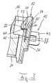
- the Locking tab 47 with its front 17 facing surface 52 on a side wall 26 or 27 molded nose 22, 23 past by their rear surface 20 slides along, and lies exactly behind the nose 22, 23, if the head 46 on said shoulder in the longitudinal slot 33 lies on.
- the holding element 13, 14 is thus in the housing 12 fixed or immobile.
- the foot region 48 projects over the underside of the housing base 29, which has a longitudinal groove 24 is provided.
- the foot area 48 the fastening tab 49 in that shown in Figure 1 Position bent outwards by 90 °, being in the longitudinal groove 24 is recorded and the side wall 26 or 27 protrudes like this is particularly evident from Figure 2.
- the mounting pin 50 in a not shown corresponding recess in the circuit board 15 is pressed or is plugged in and soldered, lies the Mounting tab 49 on a surface area of the Printed circuit board 15, preferably a solder connection will be produced.
- the plastic housing 12 is over the holding elements 13 and 14 on the printed circuit board 15 connected immovably and mechanically stressable.
- the cable connector 11 has at the front end of its housing 61 accommodating a contact arrangement 62, in that a cable, not shown, is inserted Plug component 64, the active contacts with the plug-side connection ends 39 of the connector 10 are connectable.
- Plug component 64 has the plug component 64 on both narrow side surfaces elastic or held elastic Locking tongues 67, in the locking recesses 68 the Locking tabs 47 of the holding elements 13, 14 and the lugs 22, 23 engage in the plastic housing 12.
- For Unlocking can locking tabs 67 of the cable connector 11 through handles 69 held laterally on the housing 61 to the inside are deflected so that the recesses 68 of the Noses 22, 23 and locking tabs 47 forming counter-catches come free.
Landscapes
- Coupling Device And Connection With Printed Circuit (AREA)
- Details Of Connecting Devices For Male And Female Coupling (AREA)
Abstract
Description
Die vorliegende Erfindung bezieht sich auf einen Steckverbinder nach dem Oberbegriff des Anspruchs 1.The present invention relates to a Connector according to the preamble of claim 1.
Steckverbinder dieser Art, wie sie beispielsweise in Mobiltelefonen verwendet werden, sollen zwar in immer kleiner werdender Ausführung angeboten werden, müssen jedoch stets diesselben Kräfte beim Ein- und Ausstecken eines Kabelsteckers aushalten können.Connectors of this type, as for example in Cell phones are supposed to be used in smaller and smaller sizes future versions must always be offered the same forces when inserting and removing a cable connector can endure.
Bei einem aus der DE 195 00 102 A1 bekannten Steckverbinder der eingangs genannten Art ist das Befestigungsteil durch Lötlaschen, die mit einem U-förmig umgebogenen Schenkel in der Durchgangsausnehmung gehalten sind, und das Verriegelungsteil durch ein im Abstand dazu angeordnetes separates in eine weitere Ausnehmung eingesetztes Bauteil gebildet. Diese Anordnung umfaßt zwei getrennte Teile einerseits für die Befestigung und andererseits für die Verriegelung, was auch zwei Ausnehmungen im Gehäuse bedeutet. Dies ist aufwendig. Außerdem besitzen das Verriegelungsteil und das Befestigungsteil einen Abstand in der Tiefe des Steckverbinders, was einerseits eine Verkürzung des Gehäuses verhindert und andererseits ein Kräftemoment beim Einstecken bzw. Ausstecken eines Kabelsteckers auf das mit einer Leiterplatte verlötete Befestigungsteil zur Folge haben kann. Desweiteren greift die beim Ein- und Ausstecken eines Kabelsteckers auftretende mechanische Belastung unmittelbar auf das Kunststoffgehäuse und wird über dieses auf die Lötverbindung übertragen. Dies bedeutet, daß das Kunststoffgehäuse eine entsprechende Stabilität aufweisen muß.In a connector known from DE 195 00 102 A1 of the type mentioned is the fastener through Solder tabs with a U-shaped bent leg in the Through recess are held, and the locking part by a separate one at a distance from it further recess used component formed. This Arrangement comprises two separate parts on the one hand for the Attachment and on the other hand for locking what means two recesses in the housing. This is expensive. In addition, the locking part and Fastening a distance in the depth of the Connector, which on the one hand shortened the housing prevents and on the other hand a moment of force when inserting or unplug a cable connector to the one with a PCB can result in soldered fasteners. Furthermore, it takes effect when inserting and removing one Mechanical stress occurring immediately on the plastic housing and is on this on the Transfer solder connection. This means that Plastic housing must have an appropriate stability.
Aufgabe der vorliegenden Erfindung ist es deshalb, einen Steckverbinder der eingangs genannten Art zu schaffen, bei dem die mechanische Belastung auf das Kunststoffgehäuse erheblich reduziert und insbesondere die Anzahl der Bauteile verringert ist.The object of the present invention is therefore a To create connectors of the type mentioned, in which the mechanical load on the plastic housing considerably reduced and in particular the number of components is.
Zur Lösung dieser Aufgabe sind bei einem Steckverbinder der genannten Art die im Anspruch 1 angegebenen Merkmale vorgesehen. To solve this problem with a connector mentioned type the features specified in claim 1 intended.
Durch die erfindungsgemäßen Maßnahmen ist erreicht, daß die mechanische Belastung, die insbesondere durch die Arretierung beim Ein- und Ausstecken des Kabelsteckers auftritt, vom Kunststoffgehäuse genommen und auf das Halteelement übertragen ist. Darüber hinaus dient das Halteelement gleichzeitig zum Befestigen des Kunststoffgehäuses an der Leiterplatte. Auf diese Weise sind Befestigungsbereich und Verriegelungsbereich einander unmittelbar benachbart angeordnet, so daß so gut wie keine Kraftmomente auftreten können. Desweiteren ist damit eine konstruktive Vereinfachung gegeben, da lediglich ein einziges Halteelement verwendet werden muß, das in einfacher Weise herstellbar und in das Kunststoffgehäuse einbaubar ist.The measures according to the invention ensure that the mechanical stress, in particular due to the locking occurs when inserting and removing the cable connector, from Taken plastic housing and transferred to the holding element is. In addition, the holding element serves at the same time Attach the plastic housing to the circuit board. On this is the mounting area and locking area arranged immediately adjacent to each other, so that as good as no moments of force can occur. Furthermore, it is given a constructive simplification, since only one only holding element must be used, which in simple Can be manufactured and installed in the plastic housing.
Vorteilhafte konstruktive Ausgestaltungen des Halteelements ergeben sich aus den Merkmalen des Anspruchs 2 und/oder 3.Advantageous structural designs of the holding element result from the features of claim 2 and / or 3.
Mit dem Merkmal gemäß Anspruch 4 ist erreicht, daß das
Verriegelungsteil und damit das gesamte Halteelement im
Gehäuse unverrückbar gehalten ist.With the feature according to
Sind die Merkmale gemäß Anspruch 5 vorgesehen, ist eine weitere Verbindungsmöglichkeit zwischen dem Steckverbinder und der Leiterplatte erreicht, so daß größere Haltekräfte, auch unter verschiedenen Angriffswinkeln aufgenommen werden können. Dabei kann sich eine weitere konstruktive und herstellungstechnische Vereinfachung des Halteelements dann ergeben, wenn die Merkmale gemäß Anspruch 6 vorgesehen sind. If the features are provided according to claim 5, one is further connection possibility between the connector and reached the circuit board so that greater holding forces, too can be recorded at different angles of attack. This can be another constructive and manufacturing simplification of the holding element then result if the features are provided according to claim 6.
Mit den Merkmalen des Anspruchs 7 ist eine einfache Fixierung des Hauptbereichs des Halteelementes innerhalb des Kunststoffgehäuses erreicht.With the features of claim 7 is a simple fixation the main area of the holding element within the Plastic housing reached.
Weitere vorteilhafte Ausgestaltungen ergeben sich aus den Merkmalen eines oder mehrerer der Ansprüche 8 bis 11.Further advantageous configurations result from the Features of one or more of claims 8 to 11.
Weitere Einzelheiten der Erfindung sind der folgenden Beschreibung zu entnehmen, in der die Erfindung anhand des in der Zeichnung dargestellten Ausführungsbeispieles näher beschrieben und erläutert ist. Es zeigen:
- Figur 1
- in Explosionsdarstellung und perspektivischer Vorderansicht einen Steckverbinder gemäß einem bevorzugten Ausführungsbeispiel vorliegender Erfindung,
- Figur 2
- in perspektivischer Rückansicht von oben den Steckverbinder nach Figur 1 in montiertem Zustand,
Figur 3- in vergrößerter ausschnittweiser Darstellung einen Schnitt längs der Linie III-III der Figur 2 und
Figur 4- in perspektivischer Darstellung einen mit dem Steckverbinder nach den Figuren 1 bis 3 verwendbaren Kabelstecker.
- Figure 1
- an exploded view and perspective front view of a connector according to a preferred embodiment of the present invention,
- Figure 2
- in a rear perspective view from above, the connector according to FIG. 1 in the assembled state,
- Figure 3
- an enlarged sectional view of a section along the line III-III of Figure 2 and
- Figure 4
- in perspective a usable with the connector of Figures 1 to 3 cable connector.
Der in den Figuren 1 bis 3 dargestellte Steckverbinder 10
gemäß einem bevorzugten Ausführungsbeispiel vorliegender
Erfindung wird beispielsweise in Mobiltelefone eingebaut und
dort mit einer in Figur 2 angedeuteten Leiterplatte 15
elektrisch und mechanisch verbunden. Der Steckverbinder 10
kann beispielsweise mit einem in Figur 4 dargestellten
Kabelstecker 11 verbunden werden.The
Der Steckverbinder 10 besitzt ein Kunststoffgehäuse 12, einen
im Gehäuse festgehaltenen oder mit dem Gehäuse einstückigen
Halter 36 aus elektrischem Isoliermaterial, eine
Kontaktanordnung 37, die in parallelen Ausnehmungen 38 des
Halters 36 zumindest teilweise aufgenommen ist, und zwei
spiegelbildlich zueinander angeordnete und ausgeführte
Halteelemente 13 und 14.The
Das dünnwandige Kunststoffgehäuse 12 besitzt eine etwa
quaderförmige Außenform und einen ebenfalls quaderförmigen
Innenraum 16, der zur kabelsteckerseitigen Front bzw.
Vorderseite 17 hin entsprechend dem lichten Querschnitt des
Kunststoffgehäuses offen ist. Das leiterplattenseitige Ende
bzw. Rückseite 18 des Innenraums 16 ist von einer mit den
Ausnehmungen 38 korrespondierenden Ausnehmungen 19 versehenen
Rückwand 21 abgedeckt. In einem näher der Vorderseite 17
zugewandten Bereich sind die beiden Seitenwände 26 und 27 von
der Deckwand 28 bis zum Boden 29 des Kunststoffgehäuses 12 mit
einer Schlitzanordnung 31 bzw. 32 versehen, die
spiegelbildlich zueinander angeordnet sind. Die
Schlitzanordnung 31, 32 ist an der Oberseite durch jeweils
einen parallel zur betreffenden Seitenwand 26 bzw. 27
verlaufenden Längsschlitz 33 und einen nahe dem der
Vorderseite 17 zugewandten Ende einen quer verlaufenden und in
diesen mündenden Querschlitz 34 gebildet. An der nicht
dargestellten Unterseite ist die Schlitzanordnung 31, 32
lediglich als Längsschlitz 33 ausgebildet, d.h. es ist kein
Querschlitz vorhanden. Dabei ist der untere Bereich 35 des
Längsschlitzes 33 an seinen beiden Enden gegenüber dem oberen
Bereich 30 des Längsschlitzes 33 etwas kürzer.The thin-walled
Die metallische Kontaktanordnung 37 ist in dem Halter 36 aus
Kunststoff entweder von der Rückseite 18 her eingeschoben oder
eingegossen. Der Halter 36 ist im Querschnitt länglich
rechteckförmig und zentrisch im Innenraum 16 des Gehäuses 12
angeordnet. Die nebeneinander verlaufenden Kontaktstege der
Kontaktanordnung 37 besitzen kabelsteckerseitig Anschlußenden
39 und leiterplattenseitig zur Leiterplatte 15 hin abgekröpfte
Anschlußenden 40.The
Das metallische Halteelement 13, 14 ist einstückig aus einem
Blech geformt, d.h. gestanzt und entsprechend gebogen. Das
Halteelement 13, 14 besitzt einen Hauptbereich 45, der von
einem etwas breiteren Kopf 46 abgedeckt ist, und eine
senkrecht (d.h. um 90°) zur großflächigen Ebene des
Hauptbereichs 45 und um dessen Schmalkante abgewinkelte
Verriegelungslasche 47, die in einem axialen Abstand vom Kopf
46 vorgesehen ist. Ein sich an den Hauptbereich 45
anschließender Fußbereich 48 ist im Endzustand in eine
Befestigungslasche 49 und einen Befestigungsstift 50
aufgezweigt. Der Befestigungsstift 50 liegt dabei in der Ebene
des Hauptbereichs 45, während die Befestigungslasche 49
senkrecht (d.h. um 90°) zur Ebene des Hauptbereichs 45
umgebogen ist, wobei sie in eine Richtung zeigt, die der
Richtung der Verriegelungslasche 47 entgegengesetzt ist. Die
Befestigungslasche 49 ist in einem dem Hauptbereich 45
zugewandten Teil mit einem Schlitz versehen, dessen
Innenabmessungen den Außenabmessungen des Befestigungsstiftes
50 entspricht, da der Befestigungsstift 50 aus der
Befestigungslasche 49 ausgeklinkt bzw. ausgestanzt ist. Damit
ist der Befestigungsstift 50 in Richtung der Breite des
Hauptbereichs 45 zentrisch zu diesem und besitzt an seinem
freien Ende Schrägflächen 51. Der Befestigungsstift 50 ist
wesentlich kürzer als die Befestigungslasche 49.The
Figur 1 zeigt in ausgezogenen Linien den Endzustand des
Halteelements 13, 14 wie er ist, wenn sich das Halteelement
13, 14 im Kunststoffgehäuse 12 befindet. Vor dem Einstecken
des Halteelementes 13, 14 in die Schlitzanordnung 31 bzw. 32
von der Oberseite aus befindet sich die Befestigungslasche 49
noch in der Ebene des Hauptbereichs 45 und damit in der Ebene
des Befestigungsstiftes 50, wie dies in Figur 1 anhand des
Halteelementes 13 punktiert angedeutet ist. Zur Aufnahme der
so vorgeformten Halteelemente 13 und 14 in den
Schlitzanordnungen 31, 32 sind der Längsschlitz 33 der
Seitenwand 26, 27 und der in die Deckwand 28 ragende
Querschlitz 34 entsprechend ausgebildet. Während der nahe der
Oberseite längere Bereich 35 des Längsschlitzes 33 den Kopf 46
des Halteelements 13, 14 aufnimmt, nimmt der restliche und
etwas kürzere Bereich 30 des Längsschlitzes 33 den gegenüber
dem Kopf 46 schmäleren Hauptbereich 45 auf. Dabei bildet der
Übergang vom oberen Bereich zum unteren Bereich des
Längsschlitzes 33 eine Schulter 25 (Figur 3), auf der die
Unterseite 53 des Kopfes 46 nach dem Einstecken der
Halteelemente 13, 14 aufliegt. Mit dem Einstecken des
Halteelements 13, 14 in die Schlitzanordnung 31, 32 gelangt
die Verriegelungslasche 47 in den Querschlitz 34, der in den
Innenraum 16 des Gehäuses 12 mündet. Dabei gelangt die
Verriegelungslasche 47 mit ihrer der Vorderseite 17
zugewandten Fläche 52 an einer an der Seitenwand 26 bzw. 27
angeformten Nase 22, 23 vorbei, indem sie an deren Rückfläche
20 entlanggleitet, und genau hinter der Nase 22, 23 liegt,
wenn der Kopf 46 auf der genannten Schulter im Längsschlitz 33
aufliegt. Damit ist das Halteelement 13, 14 im Gehäuse 12
fixiert bzw. unbeweglich gehalten.Figure 1 shows in solid lines the final state of
In diesem Zustand ragt der Fußbereich 48 über die Unterseite
des Gehäusebodens 29 hinaus, der mit einer Längsnut 24
versehen ist. In diesem Einbauzustand wird aus dem Fußbereich
48 die Befestigungslasche 49 in die in Figur 1 dargestellte
Lage um 90° nach außen umgebogen, wobei sie in der Längsnut 24
aufgenommen ist und die Seitenwand 26 bzw. 27 überragt, wie
dies insbesondere aus Figur 2 ersichtlich ist.In this state, the
Während der Befestigungsstift 50 in eine nicht dargestellte
entsprechende Ausnehmung in der Leiterplatte 15 eingepreßt
oder eingesteckt und verlötet wird, liegt die
Befestigungslasche 49 auf einem Oberflächenbereich der
Leiterplatte 15 auf, wobei bevorzugt eine Lötverbindung
hergestellt wird. Dadurch ist das Kunststoffgehäuse 12 über
die Halteelemente 13 und 14 an der Leiterplatte 15
unverrückbar und mechanisch beanspruchbar verbunden.During the mounting pin 50 in a not shown
corresponding recess in the
Außer zur festen Verbindung des Kunststoffgehäuses 12 mit der
Leiterplatte 15 dienen die Halteelemente 13, 14 zur
verriegelnden Halterung des in Figur 4 dargestellten
Kabelsteckers 11. Der Kabelstecker 11 besitzt am vorderen Ende
seines eine Kontaktanordnung 62 aufnehmenden Gehäuses 61, in
das ein nicht dargestellte Kabel eingeführt ist, ein
Steckerbauteil 64, dessen aktiven Kontakte mit den
steckerseitigen Anschlußenden 39 des Steckverbinders 10
verbindbar sind. Zur Verrastung von Kabelstecker 11 und
Steckverbinder 10 besitzt das Steckerbauteil 64 an beiden
schmalen Seitenflächen elastische oder elastisch gehaltene
Verriegelungszungen 67, in deren Rastausnehmungen 68 die
Verriegelungslaschen 47 der Halteelemente 13, 14 und die Nasen
22, 23 im Kunststoffgehäuse 12 verrastend greifen. Zur
Entriegelung können Verriegelungszungen 67 des Kabelsteckers
11 durch am Gehäuse 61 seitlich gehaltene Griffe 69 nach innen
ausgelenkt werden, so daß die Rastausnehmungen 68 von den die
Gegenrasten bildenden Nasen 22, 23 und Verriegelungslaschen 47
frei kommen.Except for the fixed connection of the
Claims (11)
Applications Claiming Priority (2)
| Application Number | Priority Date | Filing Date | Title |
|---|---|---|---|
| DE29613694U DE29613694U1 (en) | 1996-08-08 | 1996-08-08 | Connectors |
| DE29613694U | 1996-09-08 |
Publications (1)
| Publication Number | Publication Date |
|---|---|
| EP0828320A1 true EP0828320A1 (en) | 1998-03-11 |
Family
ID=8027544
Family Applications (1)
| Application Number | Title | Priority Date | Filing Date |
|---|---|---|---|
| EP97109524A Withdrawn EP0828320A1 (en) | 1996-08-08 | 1997-06-12 | Connector |
Country Status (4)
| Country | Link |
|---|---|
| US (1) | US6030249A (en) |
| EP (1) | EP0828320A1 (en) |
| JP (1) | JPH1079280A (en) |
| DE (1) | DE29613694U1 (en) |
Cited By (2)
| Publication number | Priority date | Publication date | Assignee | Title |
|---|---|---|---|---|
| EP0991141A2 (en) * | 1998-10-01 | 2000-04-05 | Hirose Electric Co., Ltd. | Surface-mount connector |
| US6307934B1 (en) | 1999-06-03 | 2001-10-23 | Telefonaktiebolaget Lm Ericsson (Publ) | Multiconnector for mobile telephones |
Families Citing this family (10)
| Publication number | Priority date | Publication date | Assignee | Title |
|---|---|---|---|---|
| US6398577B1 (en) | 2000-10-04 | 2002-06-04 | Molex Incorporated | Latching/unlatching system for electrical connectors |
| JP2002124329A (en) * | 2000-10-13 | 2002-04-26 | Auto Network Gijutsu Kenkyusho:Kk | Connector for mounting on substrate |
| JP4007970B2 (en) * | 2004-03-30 | 2007-11-14 | 日本航空電子工業株式会社 | Connector fixing member and connector using the same |
| JP4262708B2 (en) * | 2005-09-26 | 2009-05-13 | 住友電装株式会社 | Board connector |
| US8657632B2 (en) * | 2011-12-07 | 2014-02-25 | Cheng Uei Precision Industry Co., Ltd. | I/O connector |
| US11296467B2 (en) * | 2012-11-06 | 2022-04-05 | Server Technology, Inc. | High outlet density power distribution unit |
| CA2889216A1 (en) | 2012-11-06 | 2014-05-15 | Server Technology, Inc. | High outlet density power distribution unit |
| JP6148489B2 (en) | 2013-02-13 | 2017-06-14 | 矢崎総業株式会社 | Connector peg press-fit structure |
| DE102013102823A1 (en) * | 2013-03-19 | 2014-09-25 | Phoenix Contact Gmbh & Co. Kg | Charging plug with reinforcement element |
| USD809461S1 (en) * | 2013-11-06 | 2018-02-06 | Server Technology, Inc. | Outlet bank |
Citations (4)
| Publication number | Priority date | Publication date | Assignee | Title |
|---|---|---|---|---|
| WO1993002489A1 (en) * | 1991-07-16 | 1993-02-04 | E.I. Du Pont De Nemours And Company | Retention system for a connector housing |
| US5232379A (en) * | 1992-02-28 | 1993-08-03 | Foxconn International, Inc. | Connector with mounting means for SMT |
| EP0691712A1 (en) * | 1994-07-04 | 1996-01-10 | Framatome Connectors International | Coupling device for a pair of modules and its application to complementary electrical connectors |
| WO1996007221A1 (en) * | 1994-08-31 | 1996-03-07 | The Whitaker Corporation | Improved latch and mounting member for a surface mounted electrical connector |
Family Cites Families (19)
| Publication number | Priority date | Publication date | Assignee | Title |
|---|---|---|---|---|
| JPH0322865Y2 (en) * | 1985-04-04 | 1991-05-17 | ||
| DE3538457C2 (en) * | 1985-10-29 | 1996-02-08 | Siemens Ag | Connectors |
| DE3603250A1 (en) * | 1986-02-03 | 1987-08-06 | Allied Corp | Plug connecter, an insulating body for it, and a method for attaching the plug connecter to a printed circuit board |
| US4826442A (en) * | 1986-12-19 | 1989-05-02 | Amp Incorporated | Solderable connector retention feature |
| DE3734607C1 (en) * | 1987-10-13 | 1988-12-01 | Harting Elektronik Gmbh | Device for mounting plug connectors on printed circuit boards |
| DE8804956U1 (en) * | 1988-04-15 | 1988-06-09 | Harting Elektronik Gmbh, 4992 Espelkamp, De | |
| US4878858A (en) * | 1988-12-13 | 1989-11-07 | Molex Incorporated | Low profile shielded jack |
| US5021002A (en) * | 1989-12-20 | 1991-06-04 | Burndy Corporation | Snap-lock electrical connector with quick release |
| DE9000704U1 (en) * | 1990-01-23 | 1991-03-28 | Siemens Nixdorf Informationssysteme Ag, 4790 Paderborn, De | |
| GB2244181B (en) * | 1990-04-13 | 1994-12-21 | Oki Electric Cable | Double lock male/female type connector |
| DE9004483U1 (en) * | 1990-04-19 | 1991-03-21 | Siemens Nixdorf Informationssysteme Ag, 4790 Paderborn, De | |
| US5234357A (en) * | 1990-07-04 | 1993-08-10 | Hirose Electric Co., Ltd. | Lock mechanism for electrical connector |
| US5340329A (en) * | 1992-02-28 | 1994-08-23 | Honda Tsushin Kogyo Kabushiki Kaisha | Connector combination |
| US5259789A (en) * | 1993-02-23 | 1993-11-09 | Molex Incorporated | Retention system for circuit board mounted electrical connector |
| US5334049A (en) * | 1993-05-13 | 1994-08-02 | Molex Incorporated | Hold-down clip for board mounted electrical connector and method of use |
| US5354214A (en) * | 1993-07-23 | 1994-10-11 | Molex Incorporated | Printed circuit board electrical connector with mounting latch clip |
| US5468154A (en) * | 1993-12-15 | 1995-11-21 | Burndy Corporation | Multi-piece housing card edge connector with mounting arms |
| US5454729A (en) * | 1994-03-07 | 1995-10-03 | Wen-Te; Chuang | Electric plug and socket connecting mechanism |
| DE19500102C2 (en) * | 1995-01-04 | 1999-09-30 | Itt Cannon Gmbh | Locking device for a connector |
-
1996
- 1996-08-08 DE DE29613694U patent/DE29613694U1/en not_active Expired - Lifetime
-
1997
- 1997-06-12 EP EP97109524A patent/EP0828320A1/en not_active Withdrawn
- 1997-08-05 JP JP9210595A patent/JPH1079280A/en active Pending
- 1997-08-07 US US08/908,671 patent/US6030249A/en not_active Expired - Lifetime
Patent Citations (4)
| Publication number | Priority date | Publication date | Assignee | Title |
|---|---|---|---|---|
| WO1993002489A1 (en) * | 1991-07-16 | 1993-02-04 | E.I. Du Pont De Nemours And Company | Retention system for a connector housing |
| US5232379A (en) * | 1992-02-28 | 1993-08-03 | Foxconn International, Inc. | Connector with mounting means for SMT |
| EP0691712A1 (en) * | 1994-07-04 | 1996-01-10 | Framatome Connectors International | Coupling device for a pair of modules and its application to complementary electrical connectors |
| WO1996007221A1 (en) * | 1994-08-31 | 1996-03-07 | The Whitaker Corporation | Improved latch and mounting member for a surface mounted electrical connector |
Cited By (3)
| Publication number | Priority date | Publication date | Assignee | Title |
|---|---|---|---|---|
| EP0991141A2 (en) * | 1998-10-01 | 2000-04-05 | Hirose Electric Co., Ltd. | Surface-mount connector |
| EP0991141A3 (en) * | 1998-10-01 | 2002-02-13 | Hirose Electric Co., Ltd. | Surface-mount connector |
| US6307934B1 (en) | 1999-06-03 | 2001-10-23 | Telefonaktiebolaget Lm Ericsson (Publ) | Multiconnector for mobile telephones |
Also Published As
| Publication number | Publication date |
|---|---|
| JPH1079280A (en) | 1998-03-24 |
| DE29613694U1 (en) | 1997-12-18 |
| US6030249A (en) | 2000-02-29 |
Similar Documents
| Publication | Publication Date | Title |
|---|---|---|
| DE2054201C3 (en) | Electrical contact element intended for use in an electrical connector | |
| DE2130855C2 (en) | Connector device for a printed circuit board | |
| DE102009022094B4 (en) | stacking connector | |
| EP0898327B1 (en) | Circuit board connector | |
| DE19920981C2 (en) | Electrical connector | |
| DE2406125C3 (en) | Socket contact | |
| DE2204924A1 (en) | Electrical connector assembly | |
| DE2446081A1 (en) | ELECTRICAL CONNECTOR ARRANGEMENT | |
| DE1802589A1 (en) | Electrical connection terminal | |
| DE2212807C2 (en) | Electrical connector assembly | |
| DE2161637A1 (en) | Electrical connection element, in particular for attachment to printed circuit boards | |
| DE19621614C1 (en) | Connectors | |
| DE10119695B4 (en) | Connectors for electronic components | |
| EP0800233A1 (en) | Contact spring, specially adapted for an electrical connector | |
| DE3928751C2 (en) | ||
| DE2746273C2 (en) | Electrical connector for attaching a plug-in housing to a substrate | |
| DE10257759A1 (en) | Electrical connector with a housing and a high current contact | |
| DE102004011962A1 (en) | Connector connection, connector and assembly method | |
| EP0828320A1 (en) | Connector | |
| CH677550A5 (en) | ||
| EP0211357A2 (en) | Process for installing a contact device on a circuit board. | |
| DE19834681C1 (en) | Circuit board connection terminal has holding elements inserted into circuit board to lock side wall of housing of connection terminal | |
| EP0884801B1 (en) | Insertion shell for printed circuit board | |
| DE602004009268T2 (en) | Interconnects | |
| DE3915777A1 (en) | ELECTRICAL CONNECTOR |
Legal Events
| Date | Code | Title | Description |
|---|---|---|---|
| PUAI | Public reference made under article 153(3) epc to a published international application that has entered the european phase |
Free format text: ORIGINAL CODE: 0009012 |
|
| AK | Designated contracting states |
Kind code of ref document: A1 Designated state(s): DE FI FR GB IT SE |
|
| 17P | Request for examination filed |
Effective date: 19980909 |
|
| AKX | Designation fees paid |
Free format text: DE FI FR GB IT SE |
|
| RBV | Designated contracting states (corrected) |
Designated state(s): DE FI FR GB IT SE |
|
| 17Q | First examination report despatched |
Effective date: 20041012 |
|
| STAA | Information on the status of an ep patent application or granted ep patent |
Free format text: STATUS: THE APPLICATION IS DEEMED TO BE WITHDRAWN |
|
| 18D | Application deemed to be withdrawn |
Effective date: 20050222 |