FIELD OF THE INVENTION
This invention relates to the field of image display
systems, more particularly to methods and systems for
detecting motion in a video data sequence.
BACKGROUND OF THE INVENTION
Video image display systems create moving images by
rapidly displaying a sequence of still images, or frames.
Display systems must rapidly produce each new frame in order
to create the impression of smooth motion in the video
sequence. Each frame is formed by displaying an orthogonal
array of picture elements, or pixels. During each frame,
every pixel in the array is assigned its own brightness and
color value. Digital systems typically represent a single
pixel using three values, each value representing the
intensity of one of three component colors.
Due to the high frame rate required to smoothly portray
moving objects, display systems require a very high data
throughput. Early television broadcast standards, such as
NTSC, developed a technique called interlacing to reduce the
throughput requirements. Interlaced video systems, such as
NTSC, PAL, SECAM, and some HDTV standards, transmit each frame
as two sub-frames or fields. Each of the two fields that form
a frame contain alternate scan lines from the frame. The
first field typically contains all of the odd scan lines while
the second field contains all of the even scan lines. Because
the display forms the two sequential fields so quickly, the
viewer's eye integrates the sequential fields into a
continuous moving display. While the two separate fields are
visually integrated into a single frame, flicker is reduced by
projecting the image fields sequentially.
Modern image display systems, such as most computer
displays and some HDTV standards, are non-interlaced. Non-scanned,
or simply proscan, since the lines that form each
image are scanned sequentially from top to bottom instead of
being divided into two fields. Proscan display systems must
have a higher frame rate than interlaced systems in order to
avoid visible image flicker. Because of the higher frame
rate, proscan systems typically display more information and
have a higher resolution than comparable interlaced systems
with a lower frame rate.
Some modern image display systems with relatively high
bandwidths convert interlaced video signals to proscan in
order to improve the display quality. Additionally, some
display devices, such as the digital micromirror device (DMD),
utilize proscan data conversion to compensate for a lack of
image persistence.
Proscan conversion can introduce errors, or artifacts,
into an image depending on what the video sequence is
displaying and how the proscan conversion is being performed.
A simple form of proscan conversion simply adds the even
lines from a frame to the odd lines of a frame. Although this
form of proscan conversion is preferred for still images, it
creates problems when displaying moving objects. The problems
arise from the fact that the two fields in an image frame do
not represent the image at the same point in time. The image
data is created by scanning the original image twice, once for
every odd line and a second time for every even line,
therefore the even-line field represents data one-half of a
frame period later than the data represented by the odd-line
field. The proscan conversion described above, which creates
current frame images by filling in missing lines with pixel
data from the prior field, causes misalignment in moving
images. This misalignment is most obvious along the edges of
a moving object since the edges will appear jagged. The same
effect occurs in the center of a moving object, but unless
there is a lot of contrast within the object the artifacts are
not as noticeable.
Alternative forms of proscan conversion, which eliminate
the effects of motion, are line doubling and line averaging.
Both line doubling and line averaging use data from adjacent
pixels of the same field to fill in the missing lines of the
current field. Line doubling simply displays each line from
the present field twice, once in its proper position and once
in place of the subsequent or preceding line from the next
field. When the next field is received, the display again
uses each line of image data twice, once in its proper
position and once in place of the preceding or subsequent line
from the previous field. Line-averaging systems create a new
line of image data based on the average of the image data for
the lines above and below the created line. Because both the
line-doubling and line-averaging methods only use data from
one time sample, they avoid the problems associated with
simply combining the two image fields. Line-doubling and
line-averaging, however, reduce the effective resolution of
the image since they use less information to generate each
image.
In order to maintain the highest effective resolution
while avoiding motion artifacts, proscan conversion systems
should compensate for motion in the image data. Ideally, the
contribution of adjacent pixels from the same video field and
from the same pixel in adjacent video fields should depend on
the amount of motion in the video sequence. Therefore an
accurate motion detection system is needed to allow
optimization of the proscan conversion process.
SUMMARY OF THE INVENTION
Objects and advantages will be obvious, and will in part
appear hereinafter and will be accomplished by the present
invention which provides an improved method and system for
measuring motion in a video image and for performing a proscan
conversion on interlaced video data based on the improved
motion measurement.
According to a first embodiment of the improved method of
measuring motion, a field-difference motion value is
measuring motion, a field-difference motion value is
calculated for a missing pixel. This field-difference motion
value is used to select a proscan algorithm that will
accurately de-interlace the video data.
According to another embodiment of the improved method of
measuring motion, a field-difference motion value is
determined by calculating a first prior-field average value
equal to the average of same-pixel prior-field image data and
same-pixel prior-field two-rows-prior image data, and
determining the absolute value of the difference between same-pixel
prior-row image data and the first prior-field average
value data.
According to yet another embodiment of the improved
method of measuring motion, a motion value is determined by
determining a first prior-field average value equal to the
average of same-pixel prior-field image data and same-pixel
prior-field two-rows-prior image data, determining a first
field-difference motion value equal to the absolute value of
the difference between same-pixel prior-row image data and the
first prior-field average value data.
According to yet another embodiment of the improved
method of measuring motion, a motion value is determined by
determining a second prior-field average value equal to the
average of same-pixel prior-field image data and same-pixel
prior-field two-rows-later image data, and determining second
field-difference motion value equal to the absolute value of
the difference between same-pixel prior-row image data and the
second prior-field average value data.
According to yet another embodiment of the improved
method of measuring motion, a first field-difference motion
value is determined by determining a first prior-field average
value equal to the average of same-pixel prior-field image
data and same-pixel prior-field two-rows-prior image data,
determining a first field-difference motion value equal to the
absolute value of the difference between same-pixel prior-row
image data and the first prior-field average value data, a
second field-difference is determined by determining a second
prior-field average value equal to the average of same-pixel
prior-field image data and same-pixel prior-field two-rows-later
image data, and determining second field-difference
motion value equal to the absolute value of the difference
between same-pixel prior-row image data and the second prior-field
average value data, and a minimum of the first and
second field-difference motion values is used as the field-difference
motion value.
According to yet another embodiment of the disclosed
invention calculates a field-difference motion value for a
missing pixel, calculates a frame-difference motion value for
a missing pixel, and selects a proscan algorithm based on both
the frame-difference and the field-difference motion values to
select an algorithm for creating data for the missing pixel.
According to yet another embodiment of the disclosed
invention, a proscan algorithm is selected based on the frame-difference
motion value when the frame-difference motion value
is less than a threshold and using the field-difference motion
value when the frame-difference motion value is greater than
the threshold.
According to yet another embodiment of the disclosed
invention, a proscan algorithm is selected based on the frame-difference
motion value when the frame-difference motion value
is less than a first threshold, using the field-difference
motion value when the frame-difference motion value is greater
than a second threshold, and using a weighted average of the
frame-difference and the field-difference motion values to
select an algorithm for creating data for the missing pixel
when the frame-difference motion value is less than the first
threshold and greater than the second threshold.
According to yet another embodiment of the disclosed
invention, a method of determining a motion value for a pixel
location in a video signal is provided. The method comprises
determining a first frame-difference motion value by comparing
same-pixel prior-row image data from a current frame and a
value by comparing same-pixel next-row image data from the
current frame and the prior frame, and setting the motion
value equal to a minimum of the first frame-difference motion
value and the second frame-difference motion value.
According to yet another embodiment of the disclosed
invention, a method of determining a motion value is provided.
The method comprises comparing same-pixel prior-row image
data from a current frame and a same-pixel same-row image data
from a prior field.
According to yet another embodiment of the disclosed
invention, a logical mixer is provided. The logical mixer
comprises a first comparator outputting a selection signal
indicating whether a first signal is greater than a threshold
signal, a second comparator outputting a maximum signal equal
to the maximum of the first signal and a second signal, and a
selector receiving the selection signal, the first signal, and
the maximum signal, the selector outputting the first signal
when the first signal is less than the threshold signal and
outputting the maximum signal when the first signal is greater
than the threshold signal.
According to yet another embodiment of the disclosed
invention, a display system is provided. The display system
comprises a video processor for receiving an interlaced video
signal and converting the interlaced video signal to a
progressive-scan video signal, the video processor performs
the conversion based on a calculated field-difference motion
value for the interlaced video signal, and a display for
receiving the progressive-scan video signal from the video
processor and for displaying the progressive scan video
signal.
BRIEF DESCRIPTION OF THE DRAWINGS
For a more complete understanding of the present
invention, and the advantages thereof, reference is now made
to the following descriptions taken in conjunction with the
accompanying drawings, in which:
accompanying drawings, in which:
DETAILED DESCRIPTION OF THE PREFERRED EMBODIMENTS
Figure 1 schematically depicts video data for five
adjacent image lines from each of three sequential fields.
Each line of real image data, image data transmitted from the
interleaved source, is designated by a solid line. Each line
of created image data, data generated by the proscan
conversion, is designated by a dashed line. The spatial
relationship between image lines within a single field is
shown in Figure 1 which shows the five rows, r-2, r-1, r0, r1,
and r2, arranged vertically adjacent to each other. The
current line, the line for which motion vectors are presently
being calculated, is row r0. Three sequential fields, f-2, f-1,
and f0, are shown in chronological order from left to right.
The current field, the field for which motion vectors are
presently being calculated, is f0. As shown in Figure 1, field
f-2 is comprised of the odd-numbered rows, r-1 and r1, of a
first frame, field f-1 is comprised of even-numbered rows r-2,
r0, and r2, and field f0 is comprised of the odd-numbered rows,
r-1 and r1, from a second frame.
The dark circle on each of the image lines represents a
single pixel in the row of pixels. Unless otherwise
specified, the pixel indicated in each row of a figure is the
same pixel from each row, i.e. the pixel occupying the same
horizontal position in each of the rows indicated.
proscan conversion to create image data for pixel 102 in row r0
of field f0 from data for pixels 104, 108, and 110 of an
interlaced video signal. Typical motion detection algorithms
subtract the pixel data of pixel 104 from the pixel data of
pixel 106 and use the magnitude of the difference between the
two pixels as a rough estimate of the amount of motion in the
portion of the image depicted by pixel 102. If no motion is
detected, the proscan conversion algorithm simply uses the
data from pixel 108 for pixel 102. If a lot of motion is
detected, the average of the image data from pixel 104 and
pixel 110 is used for pixel 102. For intermediate motion
values, a weighted average of the data from each of the three
pixels is used with the weights selected to transition
smoothly from the no motion use of data from pixel 108 to the
high motion use of data from pixel 104 and pixel 110. For
example, the image data for pixel 102, ID102, is determined by:
ID102 = (k*ID108) + (1-k)*(ID104+ID110)/2
where IDx is the image data for pixel x, and k is the magnitude
of the detected motion ranging from zero to one. Since there
is no need to generate image data for the image lines which
are transmitted in each field, the motion detection algorithm
is only used on alternate lines within each field.
Figure 2 is a block diagram of a motion detection system
200 according to the prior art. In Figure 2, delay block 202
delays the current image data 204 for one field period.
Summation block 206 subtracts the delayed image data 208 from
the current image data 204. The output of the summation block 206 is a number representing the detected motion at the
current image pixel. Block 210 determines the absolute value
of the number representing the detected motion and block 212
scales the absolute value. Non-linear scaling block 212
typically subtracts a minimum threshold value from the
absolute value and limits, or clips, the result to a maximum
value. The minimum threshold provides some immunity to noise
on the motion signal while the maximum value narrows the range
of motion values that must be considered by the proscan
of motion values that must be considered by the proscan
algorithm.
In practice, the minimum threshold values determine the
point at which the proscan conversion algorithm starts using
current field data to generate image data, the point at which
k is greater than zero in the previous equation, while the
limiting value determines the point at which the proscan
conversion algorithm stops using data from a previous field to
generate image data, k equals 1. Therefore, the frame-difference
algorithm of Figure 2 uses current field and
previous frame data to determine a motion value, k, which
controls how image data is created from current field and
previous field data.
Figure 3 depicts the operation of the frame-difference
algorithm shown in Figure 2. In Figure 3, motion data for
pixel 302 is generated by subtracting the prior frame adjacent
pixel 306 (f-2, r-1) data from the current frame adjacent pixel 304 (f0, r-1) data. Not shown in Figure 3 are the absolute
value or the non-linear scaling functions of Figure 2.
Depending on the motion value determined for pixel 302, image
data for pixel 302 is created using image data from pixels
304, 308, and 310.
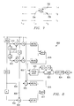
An improved frame-difference system and algorithm, which
uses data from adjacent rows above and below the missing data
line is depicted in Figures 4 and 5. In Figures 4 and 5, the
image data for row r0 is generated using data from rows r-1 and
r1. In Figure 4, the current image data 402 is compared to
image data from the previous frame 404, and image data from
the previous line 406 is compared to image data from the
previous line of the previous frame 408. Magnitude scaling
blocks 410, and 412, scale the absolute value of the results
of these comparisons resulting in a motion value 414 for the
line below the missing line and a motion value 416 for the
line above the missing line. These two motion values are
compared and the minimum motion value 418 is used to influence
the proscan algorithm. Instead of merely selecting the
to select the maximum motion value, or a weighted average of
the two calculated motion values 414 and 416. Figure 5
graphically shows the data flow through the system of Figure
4. The absolute value/non-linear scaling functional blocks,
410 and 412, of Figure 4 are not shown in Figure 5.
The frame-difference systems and algorithms represented
by Figures 2-5 reliably measure the image motion in still, or
low-motion video sequences. They may, however, fail to detect
motion in very high-motion image sequences due to the
relatively slow sample rate of the input data.
An alternative to the frame-difference systems and
algorithms of Figure 2-5 is the field-difference motion
detection system 600 of Figure 6. In Figure 6, the frame
delay of Figure 2 has been replaced by a field delay 602.
Referring to Figure 7, the field-difference system 600 of
Figure 6 compares transmitted image data from pixels 702 (f0,
r-1) and 704 (f-1, r0) to generate a detected motion value for
pixel 706 (f0, r0). As in the frame-detection system of Figure
2, the magnitude of the detect motion value is scaled by non-linear
scaling block 212 before it is used to control the
proscan conversion algorithm.
The advantage of the field-difference motion detection
system 600 of Figure 6 is its enhanced ability to detect rapid
motion compared to the detection system of Figure 2. The
enhanced detection ability is due to the increased sample rate
of the field-difference motion detection system 600 compared
to the frame sample rate used by the detection system 200 of
Figure 2. The field-difference motion detection system 600
uses current field (f0) and previous field (f-1) data instead
of current frame and previous frame data to determine a motion
value which controls how image data is created from current
field and previous field data.
Unfortunately, while the field-difference motion
detection system 600 detects very high rates of motion, it
also generates false motion values when the processed image
has a high vertical image frequency since the two data values
has a high vertical image frequency since the two data values
being compared are from different rows of the image. The
image data in each line in an image with a high vertical image
frequency is very different from the image data in adjacent
lines. Therefore, when the field-difference motion detection
system 600 compares data from pixel 702 with data from pixel
704, the line-to-line difference in still image data is
interpreted as motion.
To overcome the problems inherent with frame-difference
and field-difference motion detection systems, a new detection
system has been developed. The disclosed motion detection
system 800 is shown in Figure 8. Figure 9 depicts the logical
operation of the motion detection system 800 on image data.
The new motion detection system of Figures 8 and 9 determines
the motion vector for each pixel in each of the missing rows
by measuring and comparing four different motion vectors.
First, the system of Figures 8 and 9 measures the frame-difference
motion vector for the same pixel, the pixel in the
same horizontal location, in the lines immediately above and
below the pixel of interest. Then, the system measures the
field-difference motion vector for the same two pixels. The
lesser of the two frame-difference motion vectors and the
lesser of the two field-difference motion vectors are input
into a logical mixer and used to determine the motion vector
to be assigned to the current pixel.
Figures 8 and 9 show the steps used to calculate these
four motion vectors. As shown in Figure 8, one frame-difference
motion value is computed by comparing the current
image data 802 from pixel 902 (f0, r1) of Figure 9 with image
data 804 from the same pixel of the previous frame 904 (f-2,
r1) using block 805 while the second frame-difference motion
value is computed using image data 808 from the same pixel of
the previous line 906 (f0, r-1) and image data 810 from the
same pixel of the previous line of the previous frame 908 (f-2,
r-1) by block 809. Comparator 817 outputs the minimum value of
these two comparisons as the frame-difference motion value 816
of Figure 4.
The motion detection system of Figure 8 also calculates a
minimum field-difference motion value 818 by averaging the
image data from pixels 910 (f-1, r0) and 912 (f-1, r-2) and
comparing the average to the image data value from pixel 906
(f0, r-1) . The result is compared with a second field-difference
value determined using data from pixels 902 (f0,
r1), 910 (f-1, r0), and 914 (f-1, r2), and the minimum of the two
operations is the minimum field-difference value 818.
Although Figures 8 and 9 each show selecting the minimum
field-difference motion value 818 and the minimum frame-difference
motion value 814 of the two values created, the
motion detection system 800 could also select the maximum
motion value, the average motion value, or a weighted average
of the two motion value depending on the application.
The minimum frame-difference motion value 816 and the
minimum field-difference motion value 818 are both input into
a logical mixer 820. The logical mixer 820 outputs a motion
value which is then smoothed by an optional vertical maximum
detector 822 and an optional vertical/horizontal low pass
filter 824 before being scaled by an optional non-linear
scaling function 826. The vertical maximum detector 822
compares the motion value of the current line with the motion
value for a pixel in the same location of the previous,
current, and next lines, and uses the maximum of the three
values as the current pixel's motion value. The vertical
maximum detector 822 and the vertical/horizontal low pass
filter 824 both operate to smooth the output of the motion
detection system 800. This smoothing helps to prevent visual
artifacts from being introduced between regions in which
motion is detected and those in which no motion is detected.
Additionally, a non-linear scaling block 826, which typically
subtracts a minimum threshold value from the motion value and
limits, or clips, the result to a maximum value, also operates
to smooth the motion value determined by the circuit of Figure
8.
The disclosed motion detection circuit relies on a new
logical mixer 820 to determine the proper motion value. The
logical mixer 820 is critical to obtaining the accurate motion
data from the field and frame-difference portions of the
motion detection system 800. Because the frame-difference
portion of the motion detection system 800 is very accurate
for low frequency motion, the logical mixer block outputs the
results of the frame-difference subcircuit when the detected
motion value is low. When the detected motion value is high,
however, the logical mixer block outputs the results of the
field-difference subcircuit.
To summarize Figures 8 and 9, a motion value for the
current pixel 900 is determined by first finding a field-difference
motion value 818 and a frame-difference motion
value 816 and inputting the field-difference motion value 818
and frame-difference motion value 816 into logical mixer 820.
The frame-difference motion value is the minimum of two
frame-difference motion values obtained using adjacent data
from the same field (f0) and the previous frame (f-2). The
first frame-difference motion value is the absolute value of
the difference between image data 806 from the same pixel 906
in a prior row (r-1) of the same field (f0) and image data 808
from the same pixel 908 in the prior row (r-1) of the prior
frame (f-2). The second frame-difference motion value is the
absolute value of the difference between image data 802 from
the same pixel 902 in a following row (r1) of the same field
(f0) and image data 804 from the same pixel 904 in the
following row (r1) of the prior frame (f-2). In other words,
the frame-difference motion value is the minimum absolute
value obtained by comparing same-pixel adjacent-row same-field
image data 802, 806, with same-pixel adjacent-row prior-frame
image data 804, 808.
Also input into the logical mixer is the field-difference
motion value. The field-difference motion value is the
minimum of two field-difference motion values obtained using
adjacent data from the same field (f0) and the previous field
(f-1). The first field-difference motion value is the absolute
value of the difference between image data 806 from the same
pixel 906 of the prior row (r-1) of the same field (f0) and the
average of image data 810 from the same pixel 910 of the same
row (r0) of the prior field (f-1) and image data 812 from the
same pixel 912 of two rows prior (r-2) in the prior field (f-1) .
The second field-difference motion value is the absolute
value of the difference between image data 802 from the same
pixel 902 of the following row (r1) of the same field (f0) and
the average of image data 810 from the same pixel 910 of the
same row (r0) of the prior field (f-1) and image data 814 from
the same pixel 914 of two rows following (r2) in the prior
field (f-1) . In other words, the field-difference motion value
is the minimum absolute value obtained by comparing same-pixel
adjacent-row same-field image data 802, 806, with the average
of same-pixel same-row prior-field image data 810 and same-pixel
two-rows-adjacent prior-field image data 812, 814.
Combining the teachings of Figures 6 and 7 with that of
Figures 8 and 9, image data 810 could be substituted for the
average of image data 810 and the data 812, 814, from the same
pixels 912, 914, two rows adjacent (r-2, r2) in the prior field
(f-1).
Figure 10 shows one embodiment of a logical mixer
according to the present invention. In Figure 10, the minimum
frame-difference value (MFR) is compared to a threshold value
(TH) by comparator 1002. If the minimum frame-difference
value is greater than the threshold, then the greater of the
frame-difference motion value and the field-difference motion
value is output by selector 1004. The logical mixer 1000 of
Figure 10 selects the frame-difference motion value when there
is only a small amount of motion in the image and the greater
of the frame and field-difference motion values when there is
a lot of motion in the image. The result is that the frame-difference
motion value, which is very accurate, is used
except when both the field-difference value is greater and the
frame-difference value is significant. This allows the faster
field-difference value to be used without the fear of falsely
detecting motion in still images.
Figure 11 shows a second embodiment of a logical mixer
where the threshold value is three. In Figure 11, whenever
either one or both of the two most significant bits, MFR[3] or
MFR[2], is set, the maximum of the minimum frame difference
(MFR[3:0]) and minimum field difference (MFI[3:0]) motion
values is used by the display system to calculate a current
pixel motion value.
Figure 12 shows an embodiment of a logical mixer 1200
that implements a soft switching function. In Figure 12,
comparator 1202 compares the minimum frame difference motion
value (MFR[3:0]) to a lower threshold (THA), an intermediate
threshold (THB), and an upper threshold (THC), and outputs a
signal to multiplexer 1204 to indicate which thresholds, if
any, the minimum frame difference motion value exceeds. The
minimum frame-difference motion value is output by selector
1202 whenever it is less than a lower threshold (THA), and the
maximum of the field and frame-difference values is used when
the minimum frame-difference motion value is above an upper
threshold (THC). When the minimum frame-difference value is
above the lower threshold, but below the upper threshold
(THC), a weighted average of the minimum frame-difference and
the minimum field-difference values, determined by averaging
circuitry 1206, is used. In the example shown in Figure 12,
an intermediate threshold (THB) is used to allow one of four
combinations of the frame and field-difference values to
control the proscan algorithm.
Figure 13 shows one embodiment of a display system
including the disclosed motion detection system. In Figure
13, video data is received by receiver 1302. The video
processor 1304 includes the disclosed motion detection system
and uses the disclosed motion detection system to process the
received video data. The processed video data is then output
to display device 1306 for display.
Although to this point the disclosed motion detection
Although to this point the disclosed motion detection
system has been described in terms of block diagrams
implementing the system, it should be understood that the
system can be implemented in many ways, including hardware and
software components. Table 1 below is a listing of a software
program implementing the disclosed motion detection system.
Thus, although there has been disclosed to this point a
particular embodiment for a motion detection system and a
method thereof, it is not intended that such specific
references be considered as limitations upon the scope of this
invention except in-so-far as set forth in the following
claims. Furthermore, having described the invention in
connection with certain specific embodiments thereof, it is to
be understood that further modifications may now suggest
themselves to those skilled in the art, for example, later
data fields, if available, could also be used to determine the
motion of the image data, it is intended to cover all such
modifications as fall within the scope of the appended claims.