EP0830843A1 - Wound closure apparatus - Google Patents
Wound closure apparatus Download PDFInfo
- Publication number
- EP0830843A1 EP0830843A1 EP97202851A EP97202851A EP0830843A1 EP 0830843 A1 EP0830843 A1 EP 0830843A1 EP 97202851 A EP97202851 A EP 97202851A EP 97202851 A EP97202851 A EP 97202851A EP 0830843 A1 EP0830843 A1 EP 0830843A1
- Authority
- EP
- European Patent Office
- Prior art keywords
- suture
- needles
- cannula
- distal
- proximal
- Prior art date
- Legal status (The legal status is an assumption and is not a legal conclusion. Google has not performed a legal analysis and makes no representation as to the accuracy of the status listed.)
- Granted
Links
Images


Classifications
-
- A—HUMAN NECESSITIES
- A61—MEDICAL OR VETERINARY SCIENCE; HYGIENE
- A61B—DIAGNOSIS; SURGERY; IDENTIFICATION
- A61B17/00—Surgical instruments, devices or methods, e.g. tourniquets
- A61B17/04—Surgical instruments, devices or methods, e.g. tourniquets for suturing wounds; Holders or packages for needles or suture materials
- A61B17/0469—Suturing instruments for use in minimally invasive surgery, e.g. endoscopic surgery
-
- A—HUMAN NECESSITIES
- A61—MEDICAL OR VETERINARY SCIENCE; HYGIENE
- A61B—DIAGNOSIS; SURGERY; IDENTIFICATION
- A61B17/00—Surgical instruments, devices or methods, e.g. tourniquets
- A61B17/04—Surgical instruments, devices or methods, e.g. tourniquets for suturing wounds; Holders or packages for needles or suture materials
- A61B17/0483—Hand-held instruments for holding sutures
-
- A—HUMAN NECESSITIES
- A61—MEDICAL OR VETERINARY SCIENCE; HYGIENE
- A61B—DIAGNOSIS; SURGERY; IDENTIFICATION
- A61B17/00—Surgical instruments, devices or methods, e.g. tourniquets
- A61B17/04—Surgical instruments, devices or methods, e.g. tourniquets for suturing wounds; Holders or packages for needles or suture materials
- A61B17/06—Needles ; Sutures; Needle-suture combinations; Holders or packages for needles or suture materials
- A61B17/062—Needle manipulators
- A61B17/0625—Needle manipulators the needle being specially adapted to interact with the manipulator, e.g. being ridged to snap fit in a hole of the manipulator
-
- A—HUMAN NECESSITIES
- A61—MEDICAL OR VETERINARY SCIENCE; HYGIENE
- A61B—DIAGNOSIS; SURGERY; IDENTIFICATION
- A61B17/00—Surgical instruments, devices or methods, e.g. tourniquets
- A61B17/0057—Implements for plugging an opening in the wall of a hollow or tubular organ, e.g. for sealing a vessel puncture or closing a cardiac septal defect
-
- A—HUMAN NECESSITIES
- A61—MEDICAL OR VETERINARY SCIENCE; HYGIENE
- A61B—DIAGNOSIS; SURGERY; IDENTIFICATION
- A61B17/00—Surgical instruments, devices or methods, e.g. tourniquets
- A61B17/04—Surgical instruments, devices or methods, e.g. tourniquets for suturing wounds; Holders or packages for needles or suture materials
- A61B17/0482—Needle or suture guides
-
- A—HUMAN NECESSITIES
- A61—MEDICAL OR VETERINARY SCIENCE; HYGIENE
- A61B—DIAGNOSIS; SURGERY; IDENTIFICATION
- A61B17/00—Surgical instruments, devices or methods, e.g. tourniquets
- A61B17/00234—Surgical instruments, devices or methods, e.g. tourniquets for minimally invasive surgery
- A61B2017/00349—Needle-like instruments having hook or barb-like gripping means, e.g. for grasping suture or tissue
-
- A—HUMAN NECESSITIES
- A61—MEDICAL OR VETERINARY SCIENCE; HYGIENE
- A61B—DIAGNOSIS; SURGERY; IDENTIFICATION
- A61B17/00—Surgical instruments, devices or methods, e.g. tourniquets
- A61B17/0057—Implements for plugging an opening in the wall of a hollow or tubular organ, e.g. for sealing a vessel puncture or closing a cardiac septal defect
- A61B2017/00637—Implements for plugging an opening in the wall of a hollow or tubular organ, e.g. for sealing a vessel puncture or closing a cardiac septal defect for sealing trocar wounds through abdominal wall
-
- A—HUMAN NECESSITIES
- A61—MEDICAL OR VETERINARY SCIENCE; HYGIENE
- A61B—DIAGNOSIS; SURGERY; IDENTIFICATION
- A61B17/00—Surgical instruments, devices or methods, e.g. tourniquets
- A61B17/0057—Implements for plugging an opening in the wall of a hollow or tubular organ, e.g. for sealing a vessel puncture or closing a cardiac septal defect
- A61B2017/00646—Type of implements
- A61B2017/00663—Type of implements the implement being a suture
-
- A—HUMAN NECESSITIES
- A61—MEDICAL OR VETERINARY SCIENCE; HYGIENE
- A61B—DIAGNOSIS; SURGERY; IDENTIFICATION
- A61B17/00—Surgical instruments, devices or methods, e.g. tourniquets
- A61B17/0057—Implements for plugging an opening in the wall of a hollow or tubular organ, e.g. for sealing a vessel puncture or closing a cardiac septal defect
- A61B2017/00672—Locating means therefor, e.g. bleed back lumen
-
- A—HUMAN NECESSITIES
- A61—MEDICAL OR VETERINARY SCIENCE; HYGIENE
- A61B—DIAGNOSIS; SURGERY; IDENTIFICATION
- A61B17/00—Surgical instruments, devices or methods, e.g. tourniquets
- A61B2017/00982—General structural features
- A61B2017/00986—Malecots, e.g. slotted tubes, of which the distal end is pulled to deflect side struts
-
- A—HUMAN NECESSITIES
- A61—MEDICAL OR VETERINARY SCIENCE; HYGIENE
- A61B—DIAGNOSIS; SURGERY; IDENTIFICATION
- A61B17/00—Surgical instruments, devices or methods, e.g. tourniquets
- A61B17/04—Surgical instruments, devices or methods, e.g. tourniquets for suturing wounds; Holders or packages for needles or suture materials
- A61B17/0469—Suturing instruments for use in minimally invasive surgery, e.g. endoscopic surgery
- A61B2017/047—Suturing instruments for use in minimally invasive surgery, e.g. endoscopic surgery having at least one proximally pointing needle located at the distal end of the instrument, e.g. for suturing trocar puncture wounds starting from inside the body
-
- A—HUMAN NECESSITIES
- A61—MEDICAL OR VETERINARY SCIENCE; HYGIENE
- A61B—DIAGNOSIS; SURGERY; IDENTIFICATION
- A61B17/00—Surgical instruments, devices or methods, e.g. tourniquets
- A61B17/04—Surgical instruments, devices or methods, e.g. tourniquets for suturing wounds; Holders or packages for needles or suture materials
- A61B17/0469—Suturing instruments for use in minimally invasive surgery, e.g. endoscopic surgery
- A61B2017/0472—Multiple-needled, e.g. double-needled, instruments
Definitions
- This invention relates generally to apparatus and methods for closing a wound or hole in a body wall, and more specifically to wound closure devices using suture material.
- a puncture-type wound in a body wall can be created either unintentionally, or intentionally as part of a surgical procedure.
- the wound typically has the configuration of a hole extending through the body wall where access to the far side of the wall is available only through the wound.
- the wound in the body wall may be accidentally created but it is more likely that it will be intentionally created in a surgical procedure associated with interventional cardiology, for example.
- Surgical procedures involving interventional cardiology commonly produce a wound in the femoral or iliac artery of the patient.
- the body wall in which the wound is formed is the wail of the artery which is disposed some distance beneath the skin of the patient.
- wounds or holes are left in the tissue wall forming the arteries.
- large caliber access sheaths and dilators are used which merely accentuate the size of the wound and demand an appropriate suturing apparatus and technique for closing the wound. Wounds of this type have been addressed with direct hand pressure or specialized weights, bandages and dressings. These implements, requiring placement for extended supervised periods of time, also result in considerable discomfort to the patient.
- closure devices include bioresorbable plugs which in some cases provide a matrix which facilitates clotting. More recently, devices have been used which include needles and attached sutures which have been inserted into the vessel. The needles have been driven outwardly through the wall of the vessel where the suture ends have been captured and retrieved for knot tying.
- the wound closure device of the present invention includes a distal cannula which is insertable through the wound and functions to provide a suture on the far side of the body wall.
- a handle of the device remains on the near side of the body wall.
- a finger tab operable on the handle manipulates the suture on the far side of the body wall between radially spaced outer and inner positions.
- a needle deployment mechanism also operable on the handle, deploys needles from a proximal position to a distal position. In the distal position, the needles extend through needle holes in the surrounding tissue of the body wall, and into proximity with the suture on the far side of the body wall.
- the needles are disposed between the first and second positions of the suture so that manipulation of the suture between the first and second positions results in engaging the needle.
- the needles can then be withdrawn to capture the ends of the suture and to bring those ends through the needle holes to the near side of the body wall.
- the entire wound closure device can be retracted leaving the suture ends extending through tissue on opposite sides of the wound. Tying a knot between these ends tightens the suture across the wound to accomplish closure.
- the apparatus for threading the needle on the far side of the body wall can include a Mallicot structure having legs which are radially expandable and contractible to move the suture into threading engagement with the needles. This mechanism is operable from the handle of the apparatus on the near side of the body wall.
- the apparatus for deploying the needles between the proximal and distal positions is also operable from the handle. This apparatus not only moves the needle but also trips the threading mechanism when the needles are appropriately positioned for threading. Further operation of the deployment mechanism frees the suture loop from a tensioning mechanism after the needles have been threaded, thereby permitting the apparatus to be withdrawn from the wound with the suture appropriately positioned to facilitate closure of the wound.
- a wound closure apparatus is adapted for suturing a wound in a tissue wall.
- the apparatus includes a cannula having an axis extending between a proximal end and a distal end.
- a handle is disposed at the proximal end of the cannula.
- At least one pair of needles is disposed in proximity to the distal end of the cannula, the needle being movable between a proximal position and a distal position wherein the needle extends through the tissue wall.
- a suture manipulator carried by the cannula is insertable through the wound and operable to manipulate the suture into an engaging relationship with the needle when the needle is in the distal position.
- An associated method results in suturing a wound formed in tissue of a body wall having a near side and a far side.
- Steps of the method include providing a suture having a first end, a second end, and a suture loop extending therebetween. The first and second ends of the suture are inserted through the wound leaving the suture loop on the near side of the body wall. Inserting an unthreaded first needle and an unthreaded second needle through the tissue places the distal ends of the needles on the far side of the body wall.
- the method also includes the steps of threading the first and second needles on the far side of the wall with respective ends of the suture, and withdrawing the threaded needles together with the associated first and second ends of the sutures to the near side of the body wall. Then the suture ends can be tensioned to draw the suture loop to the far side of the body wall, and tied to draw the tissue into proximity and thereby close the wound in the body wall.
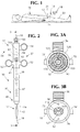
- a wound closure apparatus is illustrated in Figure 1 and designated generally by the reference numeral 10.
- the apparatus 10 is illustrated in use for closing a wound 12 in a femoral artery 14 of a patient 16.
- the wound 12 would typically have been intentionally created in order to provide access through the femoral artery 14 to the cardiovascular system of the patient 16.
- the wound 12 is formed in the tissue of a body wall which forms the femoral artery 14.
- portions of the femoral artery define the hole or wound 12 in the body wall.
- the apparatus 10 is typically introduced into the artery 14 over a guidewire 18 which extends through an incision 21 in the skin 23 of the patient 16.
- Figure 1 illustrates the suturing of a wound 12 interiorly of the skin 23, the apparatus 10 is equally adapted for use in suturing a wound in any body wall including the skin 23.
- a preferred embodiment of the wound closure apparatus 10 is illustrated in Figure 2 and consists generally of a cannula 30 having a distal section 32, a proximal section 34, and an intermediate section 36.
- the proximal section 34 comprises a handle 37
- the distal section 34 comprises a flexible catheter 45
- the intermediate section 36 comprises a generally rigid tube.
- the cannula 30 is otherwise defined by an axis 38 which extends between a proximal end 41 and a distal end 43 of the apparatus 10.
- the cannula 30 is generally hollow in order to facilitate insertion of the apparatus 10 over the guidewire 18 which is shown at both the proximal and distal ends 41 and 43 respectively.
- Graduations 47 can be provided on the exterior surface of the intermediate section 36 in order to measure the depth of the wound 12 relative to the skin 23.
- Radiopaque marker rings can also be provided on the catheter 45 to facilitate fluoroscopic guidance and X-ray contrast.
- the handle 37 includes a pair of stationary finger rings 52, and an actuator in the form of an axially movable finger ring 54 which is discussed in greater detail below.
- a finger tab 56 is also movable along the handle 37. This finger tab 56 rides within an elongate groove 58 which includes a slot 61 having a proximally facing shoulder 63.
- the embodiment of Figure 2 is also provided with a Touchy-Boast valve 65 which can be tightened to seal against the guidewire 18. Back bleeding through the catheter 45 can be evidenced through the Touchy-Boast valve 65 to provide a visual indication that the catheter 45 is located within the artery 14.
- the interior regions of the cannula 30 are illustrated in Figure 3. From this view it can be seen that the catheter 45 in this particular embodiment extends from the proximal end 41 and exits the cannula 30 through the distal end 43. Thus the catheter 45 forms a hollow tube within the hollow tube of the cannula 30.
- An inner channel 70 associated with the catheter 45 is adapted to receive not only the guidewire 18, but also a suture 72 which is described in greater detail below.
- An inner channel 74 associated with the cannula 30 is provided with a plug 76 at its distal end 43.
- This plug 76 has a distally facing outer surface 78, a proximally facing shoulder 79, and an annular recess 81 terminating within the channel 74 at a proximally facing surface 83.
- a pair of longitudinal needle bores 85, 87 are provided which extend generally parallel to the axis 38 from the cannula channel 74 to the outer surface 78.
- a pair of needles 90, 92 are mounted for reciprocal movement within the respective bores 85 and 87. These needles 90, 92 are carried by a common radial flange 94 which is disposed within the channel 74 of the cannula 30 but is suitably apertured to receive the catheter 45 along the axis 38.
- a needle return spring 96 is disposed to extend from the surface 83 of the recess 81 to the flange 94.
- a travel slack spring 98 extends from the flange 94 to a distally facing surface 101 of an elongate cylinder 103.
- This cylinder 103 which is disposed coaxial with and interiorly of the cannula 30, and is moveable by operation of the finger ring 54 within the channel 74 of the cannula 30.
- the catheter 45 extends through the cylinder 103 so that the cylinder 103 occupies a generally cylindrical space between the catheter 45 and the cannula 30.
- the finger ring 54 and attached cylinder 103 together with the springs 96, 98, the needles 90, 92 and associated flange 94 function as a deployment mechanism to initially deploy and ultimately retract the needles 90, 92.
- distal pressure on of the finger ring 54 moves the needles 90, 92 from a proximal position best illustrated in Figure 3 to a distal position best illustrated in Figure 5.
- the cylinder 103 withdraws from the spring 98 and the force of the compressed spring on the flange 94 causes the needles 90, 92 to return from the distal position illustrated in Figure 5 toward the proximal position illustrated in Figure 3.
- the combination of the cylinder 103 and finger ring 54 is also provided with a trip mechanism in the form of a tang 105 which rides within the groove 58 to engage a flange 107 on the finger tab 56.
- This flange 107 has an inclined surface 109 and a distal facing shoulder 111, discussed in greater detail below.
- a suture deployment mechanism 114 can be formed as part of the catheter 45 in general proximity to the distal surface 78 associated with the cannula 30.
- this suture manipulating mechanism 114 is formed by a plurality of slits 116 (best shown in the radial cross section view of Figure 3B) which are spaced around the circumference of the catheter 45. These slits 116 define a plurality of fingers 118 perhaps best shown in Figure 5A. Each of the fingers 118 can be provided with an intermediated living hinge 121 which facilitates radial expansion of the fingers 118 when the catheter 45 is axially compressed. This radial expansion occurs between a first position illustrated in Figure 3, where the fingers 118 have a relatively low profile, to a second position illustrated in Figure 4, where the fingers 118 have a relatively high radial profile. In combination, the expandable fingers 118 form a device commonly referred to as a Mallicot structure. Between the first, low profile position and the second, high profile position of the fingers 118, there exists a natural position described below with reference to Figure 6.
- the suture manipulating mechanism 114 also includes the finger tab 56 and a projection 123 which extends from the tab 56 through the groove 58 and into the channel 74 of the cannula 30.
- An elongate element 125 is fixed at its proximal end to the projection 123 and at its distal end to a flange 127 at the distal tip of the apparatus 10.
- This flange 127 which is apertured to receive the guidewire 18, is at least as large as the catheter 45 at the distal end 43 of the apparatus 10. It is the purpose of the finger tab 56, the element 125 and the flange 127 to move the fingers 118 between the low profile position and the high profile position.
- These fingers 118 can be maintained in the second, expanded position automatically by ensuring that the flange 107 associated with the finger tab 56 is appropriately lodged within the slot 61 associated with the groove 58.
- the finger tab 56 can be locked in the proximal, dotted position when the flange 107 falls into the slot 61 and the distally facing surface 111 of the flange 107 engages the proximally facing surface 63 of the slot 61.
- the resulting lock which holds the tab 56 in its proximal position and holds the fingers 118 in their second expanded state, is released in a preferred embodiment when the tab 105 associated with the finger ring 54 and cylinder 103 engages the flange 107 forcing it out of the slot 61.
- Distal finger pressure on the tab 56 can also facilitate movement of the fingers 118 from the high profile state toward the low profile state if the elongate element 125 can accommodate a compressive load.
- the suture 72 includes free ends 130 and 132 which can be embedded in or near the living hinge 121 of adjacent fingers 118. Between the ends 130 and 132, the suture forms a suture loop 134 which is relatively long and extends from the fingers 118 into the channel 70 of the catheter 45 and along substantially the entire length of the cannula 30 where it exits the catheter 45 through a pathway or hole 136.
- the suture loop 134 engages a suture tensioning device 138 in the form of a tab 141 formed in the wall of the cylinder 103.
- This tab 141 includes a post 143 which extends radially outwardly to receive the suture loop 134.
- the tab 141 is compressible radially inwardly by a projection 145 on the inner surface of the handle 37, best seen in Figure 5C.
- the projection 145 engages the tab 141 and moves it radially inwardly. This causes the suture 72 to clear the post 143 effectively dislodging the suture loop 134 from the tensioning device 138. This feature is particularly advantageous during operation of the apparatus 10 for reasons discussed in greater detail below.
- a preferred method for attaching the suture 72 to the fingers 118 can be best understood with reference to Figure 5A.
- the fingers 118 are further designated by the reference numerals 152, 154, 156, and 158.
- the fingers 152-158 are fully extended in the second position.
- the associated living hinges 121 are disposed at the bends of the fingers 152-158 where the fingers reach their maximum radial distance from the axis 38.
- the suture end 130 can be loosely embedded in the finger 154, the suture can then be led from the finger 154 and through a slit in the living hinge 121 associated with the finger 156. From this point, the suture loop 134 can be fed into the catheter 45 and along the length of the cannula 30.
- the suture end 132 can be loosely embedded in the finger 152 and led through a slit in the living hinge 121 associated with the leg 158.
- each of the suture ends 130, 132 forms a short section of suture which extends between adjacent legs.
- the suture end 130 extends between adjacent legs 154, 156 to form a suture portion 159, while the suture end 132 extends between opposing adjacent legs 152, 158 to form a suture portion 160.
- the finger tab 56 on the handle 37 is initially set to the distal position illustrated by the solid lines in Figure 3. This ensures that the fingers 118 forming the Mallicot structure are in the low profile state.
- the suture 72 can then be mounted on the fingers 118 and the suture loop 134 and threaded through the channel 70 of the catheter 45. After exiting the hole 136 in the catheter 45, the suture loop 134 is disposed around the post 143 in the suture tensioner 138.
- the movable finger ring 54 is placed in its proximal position so that the needles 90, 92 are retracted into the associated bores 85, 87.
- the Touchy-Boast valve 65 can also be loosened to allow insertion over the guidewire 18.
- Operation of the wound closure apparatus is begun by inserting the catheter 45 into the wound 12. If the wound 12 is in the skin 23 of the patient 16, the catheter 45 is introduced directly into the wound 12. If however, as illustrated in Figure 1, the wound occurs in a body wall, such as the wall of the femoral artery 14, the small incision 21 can be made in the skin 23 in order to gain access to the artery 14.
- the guidewire 18 will typically have been placed through the incision 21 and wound 12 as part of the surgical procedure which developed the wound 12.
- the apparatus 10 can be positioned over the guidewire 18 so that the distal tip of the catheter 45 follows the guidewire through the incision 21 and the wound 12 into the artery 14.
- the graduations 47 on the cannula 30 will provide an indication of the depth of the artery 14 relative to the skin 23.
- Radiopaque markers on the catheter 45 can be useful to facilitate fluoroscopic guidance to an operative position.
- the Touchy-Boast valve 65 also provides a visual indication of Back bleeding which would evidence proper placement within a blood vessel.
- the valve 65 can also be provided with a T-fitting to facilitate injections of X-ray contrast media through the catheter 45.
- the body wall in this case a body wall 161 of the artery 14, has a near side 163 and a far side 165. Since access to the far side 165 of the body wall 161 is severely limited, it is of particular advantage to the present invention that wound closure can be achieved without direct access to the far side 165 except through the wound 12.
- the catheter 45 is inserted through the wound 12 a distance sufficient that the fingers 118 forming a Mallicot structure are positioned on the far side 165 of the body wall 161.
- the suture ends 130, 132 illustrated in Figure 4 are positioned on the far side 165 while the suture loop 134 is positioned on the near side 163 of the body wall 161.
- This preferred operative position for the apparatus 10 is achieved by operation of the handle 37 and associated stationary rings 52. With the apparatus 10 thus disposed, the fingers can be expanded from their first low profile state illustrated in Figure 3 to their second expanded state illustrated in Figure 4. Note that this expansion of the fingers 118 results in the radial outward movement of the suture portion 159, 160.
- the needles 90, 92 can now be deployed. These needles 90, 92 are initially disposed in their associated bores 85, 87 on the near side 163 of the body wall 161. Deployment of the needles 90, 92 is accomplished by moving the finger ring 54 and associated cylinder 103 distally in the direction of an arrow 167 in Figure 5. The distally facing surface 101 of the cylinder 103 compresses the spring 98 which in turn exerts a force on the needle flange 94.
- This force which is increased with further distal movement of the finger ring 54 against the bias of the spring 96, moves the needles 90, 92 beyond the distal surface 78 and through needle holes 170 and 172 respectively, in the body wall 161. Distal movement of the needles 90, 92 ceases when the flange 94 bottoms out on the proximal facing surface 79 of the plug 76.
- the needles 90, 92 each have a needle eye 176, 178 respectively, which in a preferred embodiment is in the form of a French eye.
- these eyes 176, 178 are preferably disposed on the far side 165 of the body wall 161 and beyond the suture portions 159, 160.
- this manipulation of the suture 72 is accomplished by further distal movement of the finger ring 54 to a second position where the tang 105, riding within the groove 58, engages the inclined surface 109 of the flange 107.
- This engagement of the flange 107 by the tang 105 releases the finger tab 56 from its locked proximal position.
- the radial compression of the fingers 118 moves the suture portions 159, 160 against the associated needles 90, 92 at a position proximal to the eyes 176, 178.
- distal movement of the finger ring 54 has operated to deploy the needles 90, 92 in a first position, and to manipulate the fingers 118 in order to thread the needles in a second position of the finger ring 54.
- This manipulation of the fingers 118 in the second position is accomplished while tensioning the sutures 72 with the mechanism 138.
- movement of the finger ring 54 in a common distal direction operates to perform three sequential steps in a method for operating the apparatus 10.
- a first step associated with first distal position of the ring 54 the needles 90, 92 are deployed to a position where they can be threaded.
- the finger tab 56 is released thereby permitting contraction of the fingers 118 to facilitate threading the needles 90, 92.
- a third step associated with a third position of the finger ring 54 the suture loop 134 is released from the tensioning mechanism 138 to facilitate withdrawal of the apparatus 10.
- the needles 90, 92 can now be retracted. Initially this retraction of the needles 90, 92 causes the tensioned suture portions 159, 160 to enter the eyes 176, 178. Further retraction of the needles 90, 92 withdraws the captured suture portions 159, 160 through the associated needle holes 170, 172 in the skin 23. At this point, both of the suture ends 130, 132, as well as the suture loop 134, are disposed on the near side 163 of the wall 161. The apparatus 10 can now be withdrawn from the wound 12.
- the needles 90, 92 are preferably retracted until the eyes 176, 178 enlarged by the presence of the suture portions 152, 154 are biased against the distal surface 78 at the distal end of the cannula 30. In this position of the needles 90, 92, illustrated in the enlarged view of Figure 6A, the suture ends 130, 132 are trapped between the respective needles 90, 92 and the cannula 30 due to return spring force.
- the suture ends 130, 132 can be removed or cut from the fingers 118 and tied with a surgeon's knot in a conventional manner. Such a knot can be pushed through the incision 21 and into proximity with the wound 12 as illustrated in Figure 8.
- FIG 10 An additional embodiment of the invention is illustrated in Figure 10 and includes two needle pairs.
- the needles 90 and 92 previously discussed form one of the needle pairs while an additional needle pair comprises needles 201 and 203.
- the four needles 90, 92, 201 and 203 are displaced 90° from each other around the distal surface 78 of the cannula 30.
- the needle deployment (not shown in Figure 10) can be similar to that previously discussed where the four needles 90, 92, 201 and 203 are fixed to the common flange 94 (best illustrated in Figure 4).
- This embodiment of the invention functions to simultaneously apply two sutures to the wound 12.
- the first suture can be that previously referenced with the numeral 72.
- This suture can be laced to the suture manipulating mechanism illustrated in Figure 9 in the same manner as discussed with reference to Figure 5.
- a second color-coded suture 205 can also be laced on to the legs 152-158 of the Mallicot structure in the manner illustrated in Figure 9.
- This suture 205 having a first end 207 and a second end 209 is also characterized by a suture loop portion 210.
- the end 207 of the suture 205 is loosely held in the leg 154 of the Mallicot structure.
- the suture is then laced through the living hinge 121 and the leg 152 with the suture loop 210 extending into the channel associated with the catheter 45. As the suture loop exits this channel, it can be passed through the living hinge 121 associated with the leg 158.
- the end 209 of the second suture 205 can be loosely embedded in the leg 156.
- This configuration for the second suture 205 produces a suture portion 212 between the legs 152 and 154 and a second suture portion 214 between the legs 156 and 158.
- the two sutures 72 and 205 can form the four suture portions 159, 160, 212 and 214 for the respective needles 90, 92, 201 and 203.
- the resulting suture deployment mechanism can be operated in the manner previously discussed to thread each of the four needles associated with the embodiment of Figure 10.
- the dual suture embodiment of the suture deployment mechanism illustrated in Figure 9, can also be used with the two needle embodiment of the apparatus 10 previously discussed.
- the two needles 90-92 can be operated in the manner previously discussed to capture the suture portions 159 and 160. Then the cannula 30 and needles 90, 92 can be rotated 90° to function with respect to the suture portions 212 and 214.
- means must be provided for rotating the cannula 30, and needles 90, 92 relative to the legs 152-158 forming the Mallicot structure.
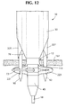
- Figure 12 illustrates a further embodiment of the wound closure apparatus 10.
- This embodiment includes the cannula 30 and catheter 45, as well as the fingers 118 and associated suture 72.
- the illustrated embodiment also includes the needles 90, 92, but in this case, the needle eyes (previously designated by the reference numerals 176, 178) are not formed as French eyes, but rather as mere slots 221, 223.
- the slots 221, 223 can be formed with a significantly lesser depth.
- the needles 90, 92 can provided with a much smaller diameter.
- the embodiment of Figure 12 provides for effective suture capture with the provision of suture capture needles 225 and 227.
- These needles 225 and 227 can be provided with a tubular configuration and a telescoping relationship with the associated needles 90, 92.
- the distal ends of the suture capture needles 225, 227 can be sharpened to facilitate their deployment through the body wall 17.
- the needles 90, 92 and associated capture needles 225, 227 can be withdrawn toward the cannula 30.
- the entire apparatus 10 can be withdrawn from the wound 12 as the method of closure continues in the manner previously described.
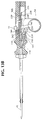
- FIGS 13A-13C illustrate another embodiment of the wound closure apparatus 10.
- This embodiment includes a suture deployment mechanism which is substantially identical to the suture deployment mechanism 114 shown in Figures 3 and 4, including the finger tab 56, which is lockable in its proximal position, and the tab 105 on the finger ring 54, which releases the finger tab 56 from its locked position when the finger ring 54 is moved distally.
- the embodiment of Figures 13A-13C includes a suture carriage 230 which is releasably secured to the finger ring 54 by a detent 232 which extends proximally from the suture carriage 230 to engage a shoulder 234 formed on a distal portion of the finger ring 54.
- the suture carriage 230 also includes a tab 141 and radially compressible post 143 which receive and release the suture loop 134 as shown in Figures 3C and 3D in connection with the first embodiment.
- the suture loop 134 in the embodiment of Figure 3 exits the catheter at a point proximal to the suture tensioner 138 and is doubled over and extended downwardly to engage the post 143 in the manner of a pulley
- the suture loop 134 according to the embodiment of Figures 13A-13C exits the catheter at a point distal to the suture carriage 230 and extends upwardly over the post 143 in a more direct manner.
- the needles of the wound closure apparatus 10 of Figures 13A-13C extend from the distal side of a flange 94 (not shown in Figures 113A-13C) mounted for reciprocation in the cannula.
- the needle control cylinder 103 of the embodiment of Figures 3-5 is replaced in this embodiment with a needle control rod 236 extending proximally from the proximal side of the flange 94.
- the finger ring 54 is coupled to the control rod 236 by a pair of axially spaced flanges 238, 240 which allow the finger ring 54 to slide between a distal point wherein a distal surface 242 of the distal flange 240 engages a drive block 244 formed on the control rod 236 and a proximal point wherein a proximal surface 248 of the distal flange 240 engages a return block 250 formed on the control rod.
- the catheter 45 is inserted into the wound 12 a distance sufficient to position the fingers 118 forming the Mallicot structure (not shown in Figures 13A-13C) on the far side of the body wall.
- the finger tab 56 can be locked into its proximal position to hold the Mallicot fingers in their expanded state so that free ends of the suture 72 extend radially outwardly.
- the finger ring 54 is moved distally to deploy the needles distally through the body wall 161.
- Distal movement of the needles begins when the distal surface of the distal flange 240 of the finger ring 54 contacts the drive block 244 of the needle control rod 236, as shown in Figure 13A, and ceases when the distal surface 252 of the finger ring 54 bottoms out on the proximal surface 254 of the suture carriage 230. At this point the detent 232 on the suture carriage 230 engages the shoulder 234 on the finger ring 54, as shown in Figure 13B.
- the ends of the suture are now extended radially outwardly and aligned with the eyes of needles.
- the finger tab 56 can be released from its locked position, allowing the fingers of the Mallicot structure to compress to their natural position, thus moving the ends of the suture into the eyes of needles.
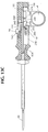
- the finger ring 54 is moved proximally, causing the suture carriage 230 to also move proximally, thereby tensioning the suture.
- the finger ring 54 continues to slide proximally along the needle control rod 236 until the proximal surface 248 of the distal flange 240 contacts the return block 250 of the needle control rod 236, thus causing the needle control rod 236 and the needles to move proximally as well.
- Suture tensioning and needle withdrawal now continue simultaneously. This results in more reliable capture of the suture ends in the needle eyes than in the previous embodiment, where needle withdrawal does not occur until after the suture has been released from the tensioner.
- the finger ring continues to be moved proximally, retracting the needles, until the proximal flange 238 of the finger ring 54 abuts the proximal end of the housing handle cavity, as shown in Figure 13C.
- the wound closure apparatus 10 can then be removed from the wound 12 and the ends of the suture tied in a conventional manner, as in the previous embodiment.
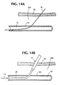
- FIGs 14A-14E are schematic illustrations of a method of using the wound closure device 10 of the present invention to place a suture in a wound before a surgical procedure.
- a guide wire 18 is inserted into the skin 23 of a patient, through a layer of fat 254, and through the wall 161 of a body vessel such as a femoral artery 14, as shown in Figure 14A.
- the flexible catheter 45 at the distal end of the wound closure device 10 of the present invention is introduced over the guidewire 18, as shown in Figure 14B.
- the wound closure device 10 is now manipulated as earlier described, and shown in greater detail in Figures 15A-15C, to place a suture 72 in the wound.
- the needles 90, 92 are first deployed through the wall 161 and the suture manipulating mechanism 114 is deployed to radially expand the end portions 159, 160 of the suture 72 in the proximity of the needle eyes 176, 178, as shown in Figure 15B.
- the needles 90, 92 are retracted and the suture loop 134 is drawn proximally to tension the suture 72, as shown in Figure 15B.
- the guidewire 18 is repositioned as necessary, and the ends 130, 132, of the suture 72 are retrieved through the opening 256 formed in the skin 23 by the device 10.
- a dilator 258 is introduced over the guidewire 18 and the wound 12 is enlarged to accommodate an access sheath of a size appropriate for the desired surgical procedure, as shown in Figure 14D.
- the sheath and the guidewire 18 are withdrawn, and the ends 130, 132 of the suture 72 tied to one another to close the wound, as shown in Figure 14E.
- the above method places the suture in the wound before dilation takes place, it allows a single, relatively small diameter (ie. 6-8 French) wound closure device 10 to be used for a wide range of procedures using different sized access sheaths (for instance, up to 10-12 French). This is in direct contrast to conventional methods which place the suture in the wound after dilation, and thus require a number of wound closure devices of different sheath sizes to be made available in order to fit in the various-sized wounds.
Abstract
Description
Claims (13)
- A wound closure apparatus for suturing a wound in a body wall, comprising:a cannula having an axis extending between a proximal end and a distal end;a handle disposed at the proximal end of the cannula;a catheter coupled to the distal end of the cannula, the catheter being sized and configured to extend through the wound in the body wall;a pair of needles movable from a proximal position in proximity to the cannula to a distal position in proximity to the catheter, each of the needles having a proximal end and a distal end;a suture having a first end, a second end, and a suture loop disposed between the first and second ends;a suture manipulator in the catheter for containing the suture ends and moving the suture ends relative to the needles;an actuator mounted for reciprocation in cannula, the actuator includingfirst means for cooperating with the needles to move the needles from the proximal position to the distal position, andsecond means for cooperating with the suture manipulator to move the suture ends into threading engagement with the needles.
- The wound closure apparatus according to claim 1, wherein:the wound closure apparatus further comprises a suture tensioning mechanism for releasably supporting the suture loop, the suture tensioning mechanism being mounted for reciprocation in the cannula; andthe actuator further comprises third means for cooperating with the suture carriage to prevent the suture from slackening.
- A wound closure apparatus for suturing a wound in a body wall, comprising:a cannula having an axis extending between a proximal end and a distal end;a handle disposed at the proximal end of the cannula;a catheter coupled to the distal end of the cannula, the catheter being sized and configured to extend through the wound in the body wall;pair of needles mounted for reciprocation within the cannula;a needle deployment mechanism in the cannula for controlling movement of the needles between a proximal position in the cannula and a distal position in proximity to the catheter, each of the needles having a proximal end and a distal end;a suture having a first end, and a second end, and a suture loop disposed belween the first and second ends; a suture manipulator in the catheter for containing the suture ends and moving the suture ends relative to the needles;a suture tensioning mechanism for releasably supporting the suture loop and preventing slackening of the suture; andactuator means mounted in the cannula and cooperating with the suture manipulator, the needle deployment mechanism and the suture tensioning mechanism to control deployment, threading, and retraction of the needles, and to maintain sufficient tension on the suture as the needles are being deployed, threaded, and withdrawn.
- The wound closure apparatus according to claim 3, wherein the actuation means comprises an actuator including:first engagement means for engaging the needle deployment mechanism;second engagement means for engaging the suture tensioning mechanism; andthird engagement means for engaging the suture manipulator.
- The wound closure apparatus according to claim 4, wherein the needle deployment mechanism includes:drive means for cooperating with the first engagement means to control distal movement of the needles; andreturn means for cooperating with the first engagement means to control proximal movement of the needles.
- The wound closure apparatus according to claim 5, wherein the actuator is mounted for sliding movement between:a first position wherein the first engagament means engages the drive means of the needle deployment mechanism to initiate distal movement of the needle;a second position wherein the second engagement means engages the suture tensioning means; anda third position wherein the first engagement means engages the return means of the needle deployment mechanism to initiate proximal movement of the needles.
- The wound closure apparatus according to claim 6, wherein:the second position is located distally of the first position; andthe third position is located proximally of the first and second positions.
- The wound closure apparatus according to claim 3, wherein the needle deployment mechanism comprises a needle support assembly, the needle support assembly including:a flange mounted for reciprocation in the cannula, the flange having a proximal side and a distal side, the distal side supporting the proximal ends of the needles;a control rod extending proximally from the proximal side of the flange;a drive block projecting radially from the control rod; anda return block projecting radially from the control rod and located proximally of the drive block.
- The wound closure apparatus according to claim 8, wherein the actuation means comprises:an actuator mounted for sliding movement on the control rod; anda flange extending from the actuator, the flange having a distal side for engaging the drive block on the control rod to push the needle support assembly distally in response to distal movement of the actuator, anda proximal side for engaging the return block on the control rod to push the needle support assembly proximally in response to proximal movement of the actuator.
- The wound closure apparatus according to claim 4, wherein the suture tensioning mechanism includes:a suture carriage mounted for reciprocation in the cannula and located distally of the actuator, anda detent extending proximally from the suture carriage; andthe second engagement means includes a shoulder formed on a distal portion of the actuator for engaging the detent on the suture carriage when the actuator is moved into the second position;
whereby movement of the actuator from the second position to the third position causes the suture tensioning mechanism to move proximally to tension the suture. - The wound closure apparatus according to claim 3, wherein the suture manipulator comprises:a plurality of flexible legs formed in the catheter, the legs having a first radially contracted position and a second radially extended position, the legs being biased to the first radially contracten position; andcontrol means for moving the legs from the first radially contracted position to the second radially expanded position.
- The wound closure apparatus according to claim 11, wherein the control means comprises:a tab mounted for movement on the cannula;an elongate element having a proximal end coupled to the tab and a distal end coupled to the distal end of the catheter, the elongate element exerting a compressive force on the catheter when the tab is moved from a distal position to a proximal position, thereby causing the legs to move to the second radially extended position; and locking means for releasably locking the tab in the proximal position.
- The wound closure apparatus according to claim 12, wherein the actuation means comprises:an actuator mounted for reciprocation in the cannula; anda finger extending from the actuator and engaging the tab to release lhe locking means, allowing the tab to move to the proximal position and the legs to move to the first radially contracted position in response to distal movement of the actuator.
Applications Claiming Priority (2)
| Application Number | Priority Date | Filing Date | Title |
|---|---|---|---|
| US715714 | 1985-03-25 | ||
| US08/715,714 US5846253A (en) | 1995-07-14 | 1996-09-19 | Wound closure apparatus and method |
Publications (2)
| Publication Number | Publication Date |
|---|---|
| EP0830843A1 true EP0830843A1 (en) | 1998-03-25 |
| EP0830843B1 EP0830843B1 (en) | 2004-07-21 |
Family
ID=24875187
Family Applications (1)
| Application Number | Title | Priority Date | Filing Date |
|---|---|---|---|
| EP97202851A Expired - Lifetime EP0830843B1 (en) | 1996-09-19 | 1997-09-17 | Wound closure apparatus |
Country Status (5)
| Country | Link |
|---|---|
| US (2) | US5846253A (en) |
| EP (1) | EP0830843B1 (en) |
| AT (1) | ATE271348T1 (en) |
| CA (1) | CA2212306A1 (en) |
| DE (1) | DE69729920T2 (en) |
Cited By (8)
| Publication number | Priority date | Publication date | Assignee | Title |
|---|---|---|---|---|
| WO1999065404A1 (en) * | 1998-06-18 | 1999-12-23 | Boston Scientific Limited | Snap handle assembly for an endoscopic instrument |
| WO2015047656A1 (en) * | 2013-09-25 | 2015-04-02 | Medtronic Vascular Inc. | Suturing device for sealing an opening in a blood vessel or other biological structure |
| WO2015047654A1 (en) * | 2013-09-25 | 2015-04-02 | Medtronic Vascular Inc. | Suturing device for sealing an opening in a blood vessel or other biological structure |
| US9265488B2 (en) | 2013-03-13 | 2016-02-23 | Medtronic Vascular, Inc. | Suturing device and method for sealing an opening in a blood vessel or other biological structure |
| EP3148447A4 (en) * | 2014-06-02 | 2018-03-21 | Medeon Biodesign, Inc. | Systems and methods for suture delivery |
| EP2967538B1 (en) * | 2013-03-13 | 2018-07-04 | Medtronic Vascular Inc. | Suturing device for sealing an opening in a blood vessel or other biological structure |
| WO2019103615A3 (en) * | 2017-11-24 | 2019-07-04 | Mediclose Solutions B.V. | Suture device |
| EP3641661A4 (en) * | 2017-06-19 | 2021-01-20 | The Feinstein Institute for Medical Research | Hernia repair device |
Families Citing this family (239)
| Publication number | Priority date | Publication date | Assignee | Title |
|---|---|---|---|---|
| US6036699A (en) | 1992-12-10 | 2000-03-14 | Perclose, Inc. | Device and method for suturing tissue |
| US6355050B1 (en) | 1992-12-10 | 2002-03-12 | Abbott Laboratories | Device and method for suturing tissue |
| US5527322A (en) | 1993-11-08 | 1996-06-18 | Perclose, Inc. | Device and method for suturing of internal puncture sites |
| US6562052B2 (en) | 1995-08-24 | 2003-05-13 | Sutura, Inc. | Suturing device and method |
| US6117144A (en) | 1995-08-24 | 2000-09-12 | Sutura, Inc. | Suturing device and method for sealing an opening in a blood vessel or other biological structure |
| US6436109B1 (en) | 1996-06-11 | 2002-08-20 | X-Site, L.L.C. | Device and method for suturing blood vessels and the like |
| US5766183A (en) * | 1996-10-21 | 1998-06-16 | Lasersurge, Inc. | Vascular hole closure |
| ATE445366T1 (en) | 1997-06-27 | 2009-10-15 | Univ Columbia | DEVICE FOR REPAIRING CIRCUIT VALVES |
| FR2768324B1 (en) | 1997-09-12 | 1999-12-10 | Jacques Seguin | SURGICAL INSTRUMENT FOR PERCUTANEOUSLY FIXING TWO AREAS OF SOFT TISSUE, NORMALLY MUTUALLY REMOTE, TO ONE ANOTHER |
| US6139556A (en) * | 1997-10-29 | 2000-10-31 | X-Site, L.L.C. | Device and method for suturing blood vessels and the like |
| AU2003212025B2 (en) * | 1998-03-09 | 2005-12-08 | Nobles Medical Technologies, Inc. | Suturing device for sealing an opening in a blood vessel |
| US6110185A (en) * | 1999-01-19 | 2000-08-29 | Medtronic, Inc. | Cannula having integral suture tourniquet |
| US7235087B2 (en) | 1999-03-04 | 2007-06-26 | Abbott Park | Articulating suturing device and method |
| US7001400B1 (en) | 1999-03-04 | 2006-02-21 | Abbott Laboratories | Articulating suturing device and method |
| US20040092964A1 (en) | 1999-03-04 | 2004-05-13 | Modesitt D. Bruce | Articulating suturing device and method |
| US8137364B2 (en) | 2003-09-11 | 2012-03-20 | Abbott Laboratories | Articulating suturing device and method |
| US6964668B2 (en) | 1999-03-04 | 2005-11-15 | Abbott Laboratories | Articulating suturing device and method |
| US7842048B2 (en) | 2006-08-18 | 2010-11-30 | Abbott Laboratories | Articulating suture device and method |
| US6136010A (en) | 1999-03-04 | 2000-10-24 | Perclose, Inc. | Articulating suturing device and method |
| US7811296B2 (en) | 1999-04-09 | 2010-10-12 | Evalve, Inc. | Fixation devices for variation in engagement of tissue |
| US20040044350A1 (en) | 1999-04-09 | 2004-03-04 | Evalve, Inc. | Steerable access sheath and methods of use |
| US7226467B2 (en) | 1999-04-09 | 2007-06-05 | Evalve, Inc. | Fixation device delivery catheter, systems and methods of use |
| US8216256B2 (en) | 1999-04-09 | 2012-07-10 | Evalve, Inc. | Detachment mechanism for implantable fixation devices |
| US10327743B2 (en) | 1999-04-09 | 2019-06-25 | Evalve, Inc. | Device and methods for endoscopic annuloplasty |
| US6752813B2 (en) * | 1999-04-09 | 2004-06-22 | Evalve, Inc. | Methods and devices for capturing and fixing leaflets in valve repair |
| ATE484241T1 (en) | 1999-04-09 | 2010-10-15 | Evalve Inc | METHOD AND DEVICE FOR HEART VALVE REPAIR |
| US6991643B2 (en) | 2000-12-20 | 2006-01-31 | Usgi Medical Inc. | Multi-barbed device for retaining tissue in apposition and methods of use |
| US7637905B2 (en) | 2003-01-15 | 2009-12-29 | Usgi Medical, Inc. | Endoluminal tool deployment system |
| US7618426B2 (en) | 2002-12-11 | 2009-11-17 | Usgi Medical, Inc. | Apparatus and methods for forming gastrointestinal tissue approximations |
| US7416554B2 (en) | 2002-12-11 | 2008-08-26 | Usgi Medical Inc | Apparatus and methods for forming and securing gastrointestinal tissue folds |
| US6626899B2 (en) | 1999-06-25 | 2003-09-30 | Nidus Medical, Llc | Apparatus and methods for treating tissue |
| US8574243B2 (en) | 1999-06-25 | 2013-11-05 | Usgi Medical, Inc. | Apparatus and methods for forming and securing gastrointestinal tissue folds |
| AU6059200A (en) | 1999-07-02 | 2001-01-22 | Quickpass, Inc. | Suturing device |
| US6358258B1 (en) | 1999-09-14 | 2002-03-19 | Abbott Laboratories | Device and method for performing end-to-side anastomosis |
| US6190396B1 (en) | 1999-09-14 | 2001-02-20 | Perclose, Inc. | Device and method for deploying and organizing sutures for anastomotic and other attachments |
| US6203554B1 (en) | 1999-11-23 | 2001-03-20 | William Roberts | Apparatus, kit and methods for puncture site closure |
| US6451031B1 (en) | 2000-03-21 | 2002-09-17 | X-Site, L.L.C. | Blood vessel suturing device with single guide-wire/needle receiving lumen |
| WO2001095809A1 (en) * | 2000-06-14 | 2001-12-20 | Sterilis, Inc. | Suturing method and apparatus |
| US6558399B1 (en) | 2000-06-30 | 2003-05-06 | Abbott Laboratories | Devices and method for handling a plurality of suture elements during a suturing procedure |
| US6520973B1 (en) * | 2000-08-30 | 2003-02-18 | Ethicon Endo-Surgery, Inc. | Anastomosis device having an improved needle driver |
| WO2002017797A1 (en) * | 2000-09-01 | 2002-03-07 | Advanced Vascular Technologies, Llc | Endovascular fastener and grafting apparatus and method |
| US6709442B2 (en) * | 2000-09-01 | 2004-03-23 | Onux Medical, Inc. | Vascular bypass grafting instrument and method |
| US6837893B2 (en) | 2000-09-01 | 2005-01-04 | Onux Medical, Inc. | Multi-fastener surgical apparatus and method |
| US6730102B1 (en) | 2000-11-06 | 2004-05-04 | Abbott Laboratories | Systems, devices and methods for deploying needles |
| US6524321B2 (en) * | 2001-01-03 | 2003-02-25 | Nozomu Kanesaka | Closure device for puncture in vessel |
| US6454777B1 (en) | 2001-02-27 | 2002-09-24 | David T. Green | Apparatus and method for suturing a blood vessel |
| US7204841B2 (en) * | 2001-02-27 | 2007-04-17 | Green David T | Apparatus for suturing a blood vessel |
| US7041119B2 (en) * | 2001-02-27 | 2006-05-09 | Green David T | Apparatus for suturing a blood vessel |
| FR2824253B1 (en) * | 2001-05-04 | 2005-02-18 | Francis Navarro | INTRUMENT FOR CLOSING BY SUTURE SUBCUTANEOUS AN ORIFICE REALIZED IN THE ABDOMINAL WALL OF A PATIENT |
| US20030078601A1 (en) * | 2001-10-22 | 2003-04-24 | Oleg Shikhman | Crimping and cutting device |
| US20080249545A1 (en) * | 2007-04-06 | 2008-10-09 | Interventional Therapies | Suturing, crimping and cutting device |
| WO2003034924A1 (en) * | 2001-10-22 | 2003-05-01 | Interventional Therapies, L.L.C. | Wound suturing device |
| US6575971B2 (en) | 2001-11-15 | 2003-06-10 | Quantum Cor, Inc. | Cardiac valve leaflet stapler device and methods thereof |
| US7048754B2 (en) | 2002-03-01 | 2006-05-23 | Evalve, Inc. | Suture fasteners and methods of use |
| US6984237B2 (en) | 2002-05-22 | 2006-01-10 | Orthopaedic Biosystems Ltd., Inc. | Suture passing surgical instrument |
| ES2298556T3 (en) * | 2002-09-23 | 2008-05-16 | Nmt Medical, Inc. | SEPTAL PUNCTURE DEVICE. |
| WO2004054156A2 (en) * | 2002-12-06 | 2004-06-24 | Fast Country, Inc. | Systems and methods for providing interactive guest resources |
| US7942884B2 (en) | 2002-12-11 | 2011-05-17 | Usgi Medical, Inc. | Methods for reduction of a gastric lumen |
| US7942898B2 (en) | 2002-12-11 | 2011-05-17 | Usgi Medical, Inc. | Delivery systems and methods for gastric reduction |
| US7160309B2 (en) | 2002-12-31 | 2007-01-09 | Laveille Kao Voss | Systems for anchoring a medical device in a body lumen |
| US8382793B2 (en) * | 2003-01-14 | 2013-02-26 | Radi Medical Systems Ab | Introducer sheath |
| US7621924B2 (en) * | 2003-04-16 | 2009-11-24 | Tyco Healthcare Group Lp | Method and apparatus for radical prostatectomy anastomosis including an anchor for engaging a body vessel and deployable sutures |
| US10667823B2 (en) | 2003-05-19 | 2020-06-02 | Evalve, Inc. | Fixation devices, systems and methods for engaging tissue |
| ATE407628T1 (en) * | 2003-06-06 | 2008-09-15 | Abbott Lab | ADJUSTMENT AND POSITIONING ADAPTER FOR MEDICAL INSTRUMENTS |
| US8216252B2 (en) | 2004-05-07 | 2012-07-10 | Usgi Medical, Inc. | Tissue manipulation and securement system |
| US7462188B2 (en) | 2003-09-26 | 2008-12-09 | Abbott Laboratories | Device and method for suturing intracardiac defects |
| US7347863B2 (en) | 2004-05-07 | 2008-03-25 | Usgi Medical, Inc. | Apparatus and methods for manipulating and securing tissue |
| US7361180B2 (en) | 2004-05-07 | 2008-04-22 | Usgi Medical, Inc. | Apparatus for manipulating and securing tissue |
| US20050251189A1 (en) | 2004-05-07 | 2005-11-10 | Usgi Medical Inc. | Multi-position tissue manipulation assembly |
| US7449024B2 (en) | 2003-12-23 | 2008-11-11 | Abbott Laboratories | Suturing device with split arm and method of suturing tissue |
| US7976539B2 (en) | 2004-03-05 | 2011-07-12 | Hansen Medical, Inc. | System and method for denaturing and fixing collagenous tissue |
| US7703459B2 (en) | 2004-03-09 | 2010-04-27 | Usgi Medical, Inc. | Apparatus and methods for mapping out endoluminal gastrointestinal surgery |
| US9713465B1 (en) * | 2004-04-19 | 2017-07-25 | Granit Medical Innovation Llc | Surgical closure device and associated method |
| US7520884B2 (en) | 2004-05-07 | 2009-04-21 | Usgi Medical Inc. | Methods for performing gastroplasty |
| US7736374B2 (en) | 2004-05-07 | 2010-06-15 | Usgi Medical, Inc. | Tissue manipulation and securement system |
| US8057511B2 (en) | 2004-05-07 | 2011-11-15 | Usgi Medical, Inc. | Apparatus and methods for positioning and securing anchors |
| US8257394B2 (en) | 2004-05-07 | 2012-09-04 | Usgi Medical, Inc. | Apparatus and methods for positioning and securing anchors |
| US7918869B2 (en) | 2004-05-07 | 2011-04-05 | Usgi Medical, Inc. | Methods and apparatus for performing endoluminal gastroplasty |
| US8444657B2 (en) | 2004-05-07 | 2013-05-21 | Usgi Medical, Inc. | Apparatus and methods for rapid deployment of tissue anchors |
| US20050267520A1 (en) | 2004-05-12 | 2005-12-01 | Modesitt D B | Access and closure device and method |
| CA2566666C (en) | 2004-05-14 | 2014-05-13 | Evalve, Inc. | Locking mechanisms for fixation devices and methods of engaging tissue |
| ZA200610827B (en) | 2004-05-21 | 2008-07-30 | Neatstich Ltd | Suture device |
| US8475476B2 (en) * | 2004-06-01 | 2013-07-02 | Cook Medical Technologies Llc | System and method for accessing a body cavity |
| US8206417B2 (en) | 2004-06-09 | 2012-06-26 | Usgi Medical Inc. | Apparatus and methods for optimizing anchoring force |
| US7695493B2 (en) | 2004-06-09 | 2010-04-13 | Usgi Medical, Inc. | System for optimizing anchoring force |
| US7736379B2 (en) | 2004-06-09 | 2010-06-15 | Usgi Medical, Inc. | Compressible tissue anchor assemblies |
| US7678135B2 (en) | 2004-06-09 | 2010-03-16 | Usgi Medical, Inc. | Compressible tissue anchor assemblies |
| US7931661B2 (en) | 2004-06-14 | 2011-04-26 | Usgi Medical, Inc. | Apparatus and methods for performing transluminal gastrointestinal procedures |
| US20060293612A1 (en) * | 2004-06-24 | 2006-12-28 | Boston Scientific Scimed, Inc. | Apparatus and method for treating occluded vasculature |
| US7678133B2 (en) | 2004-07-10 | 2010-03-16 | Arstasis, Inc. | Biological tissue closure device and method |
| JP5124274B2 (en) | 2004-09-27 | 2013-01-23 | エヴァルヴ インコーポレイテッド | Method and apparatus for grasping and evaluating tissue |
| US8052592B2 (en) | 2005-09-27 | 2011-11-08 | Evalve, Inc. | Methods and devices for tissue grasping and assessment |
| JP4786662B2 (en) * | 2004-09-27 | 2011-10-05 | スーチュラ,インコーポレイテッド | Suture device handle |
| US7909851B2 (en) | 2006-02-03 | 2011-03-22 | Biomet Sports Medicine, Llc | Soft tissue repair device and associated methods |
| US9017381B2 (en) | 2007-04-10 | 2015-04-28 | Biomet Sports Medicine, Llc | Adjustable knotless loops |
| US8088130B2 (en) | 2006-02-03 | 2012-01-03 | Biomet Sports Medicine, Llc | Method and apparatus for coupling soft tissue to a bone |
| US7658751B2 (en) | 2006-09-29 | 2010-02-09 | Biomet Sports Medicine, Llc | Method for implanting soft tissue |
| US8298262B2 (en) | 2006-02-03 | 2012-10-30 | Biomet Sports Medicine, Llc | Method for tissue fixation |
| US8128658B2 (en) | 2004-11-05 | 2012-03-06 | Biomet Sports Medicine, Llc | Method and apparatus for coupling soft tissue to bone |
| US8118836B2 (en) | 2004-11-05 | 2012-02-21 | Biomet Sports Medicine, Llc | Method and apparatus for coupling soft tissue to a bone |
| US7905904B2 (en) | 2006-02-03 | 2011-03-15 | Biomet Sports Medicine, Llc | Soft tissue repair device and associated methods |
| US9801708B2 (en) | 2004-11-05 | 2017-10-31 | Biomet Sports Medicine, Llc | Method and apparatus for coupling soft tissue to a bone |
| US8303604B2 (en) | 2004-11-05 | 2012-11-06 | Biomet Sports Medicine, Llc | Soft tissue repair device and method |
| US7749250B2 (en) | 2006-02-03 | 2010-07-06 | Biomet Sports Medicine, Llc | Soft tissue repair assembly and associated method |
| US8137382B2 (en) | 2004-11-05 | 2012-03-20 | Biomet Sports Medicine, Llc | Method and apparatus for coupling anatomical features |
| US8361113B2 (en) | 2006-02-03 | 2013-01-29 | Biomet Sports Medicine, Llc | Method and apparatus for coupling soft tissue to a bone |
| US8470028B2 (en) | 2005-02-07 | 2013-06-25 | Evalve, Inc. | Methods, systems and devices for cardiac valve repair |
| EP3967269A3 (en) | 2005-02-07 | 2022-07-13 | Evalve, Inc. | Systems and devices for cardiac valve repair |
| JP2006296578A (en) * | 2005-04-18 | 2006-11-02 | Olympus Medical Systems Corp | Treatment tool for endoscope |
| AU2006247355B2 (en) | 2005-05-12 | 2013-01-10 | Arstasis, Inc. | Access and closure device and method |
| US8038687B2 (en) * | 2005-05-17 | 2011-10-18 | St. Jude Medical Puerto Rico Llc | Suture loop closure device |
| US9585651B2 (en) | 2005-05-26 | 2017-03-07 | Usgi Medical, Inc. | Methods and apparatus for securing and deploying tissue anchors |
| US8298291B2 (en) | 2005-05-26 | 2012-10-30 | Usgi Medical, Inc. | Methods and apparatus for securing and deploying tissue anchors |
| EP1909655A2 (en) | 2005-06-20 | 2008-04-16 | Sutura, Inc. | Method and apparatus for applying a knot to a suture |
| US8267947B2 (en) | 2005-08-08 | 2012-09-18 | Abbott Laboratories | Vascular suturing device |
| US8083754B2 (en) | 2005-08-08 | 2011-12-27 | Abbott Laboratories | Vascular suturing device with needle capture |
| US7883517B2 (en) | 2005-08-08 | 2011-02-08 | Abbott Laboratories | Vascular suturing device |
| US20070060895A1 (en) | 2005-08-24 | 2007-03-15 | Sibbitt Wilmer L Jr | Vascular closure methods and apparatuses |
| US8920442B2 (en) | 2005-08-24 | 2014-12-30 | Abbott Vascular Inc. | Vascular opening edge eversion methods and apparatuses |
| US9456811B2 (en) | 2005-08-24 | 2016-10-04 | Abbott Vascular Inc. | Vascular closure methods and apparatuses |
| US20070118152A1 (en) * | 2005-11-21 | 2007-05-24 | Page Thomas C | Surgical suture passer |
| US7632308B2 (en) | 2005-11-23 | 2009-12-15 | Didier Loulmet | Methods, devices, and kits for treating mitral valve prolapse |
| US8726909B2 (en) | 2006-01-27 | 2014-05-20 | Usgi Medical, Inc. | Methods and apparatus for revision of obesity procedures |
| US8562645B2 (en) | 2006-09-29 | 2013-10-22 | Biomet Sports Medicine, Llc | Method and apparatus for forming a self-locking adjustable loop |
| US8562647B2 (en) | 2006-09-29 | 2013-10-22 | Biomet Sports Medicine, Llc | Method and apparatus for securing soft tissue to bone |
| US9149267B2 (en) | 2006-02-03 | 2015-10-06 | Biomet Sports Medicine, Llc | Method and apparatus for coupling soft tissue to a bone |
| US8597327B2 (en) | 2006-02-03 | 2013-12-03 | Biomet Manufacturing, Llc | Method and apparatus for sternal closure |
| US9078644B2 (en) | 2006-09-29 | 2015-07-14 | Biomet Sports Medicine, Llc | Fracture fixation device |
| US10517587B2 (en) | 2006-02-03 | 2019-12-31 | Biomet Sports Medicine, Llc | Method and apparatus for forming a self-locking adjustable loop |
| US9538998B2 (en) | 2006-02-03 | 2017-01-10 | Biomet Sports Medicine, Llc | Method and apparatus for fracture fixation |
| US8652172B2 (en) | 2006-02-03 | 2014-02-18 | Biomet Sports Medicine, Llc | Flexible anchors for tissue fixation |
| US8801783B2 (en) | 2006-09-29 | 2014-08-12 | Biomet Sports Medicine, Llc | Prosthetic ligament system for knee joint |
| US11259792B2 (en) | 2006-02-03 | 2022-03-01 | Biomet Sports Medicine, Llc | Method and apparatus for coupling anatomical features |
| US11311287B2 (en) | 2006-02-03 | 2022-04-26 | Biomet Sports Medicine, Llc | Method for tissue fixation |
| US8968364B2 (en) | 2006-02-03 | 2015-03-03 | Biomet Sports Medicine, Llc | Method and apparatus for fixation of an ACL graft |
| US8936621B2 (en) | 2006-02-03 | 2015-01-20 | Biomet Sports Medicine, Llc | Method and apparatus for forming a self-locking adjustable loop |
| US8652171B2 (en) | 2006-02-03 | 2014-02-18 | Biomet Sports Medicine, Llc | Method and apparatus for soft tissue fixation |
| US9408599B2 (en) | 2006-02-03 | 2016-08-09 | Biomet Sports Medicine, Llc | Method and apparatus for coupling soft tissue to a bone |
| WO2007092323A1 (en) * | 2006-02-07 | 2007-08-16 | Sutura, Inc. | Reverse tapered guidewire and method of use |
| US7731727B2 (en) * | 2006-04-26 | 2010-06-08 | Lsi Solutions, Inc. | Medical instrument to place a pursestring suture, open a hole and pass a guidewire |
| US8870916B2 (en) | 2006-07-07 | 2014-10-28 | USGI Medical, Inc | Low profile tissue anchors, tissue anchor systems, and methods for their delivery and use |
| US11259794B2 (en) | 2006-09-29 | 2022-03-01 | Biomet Sports Medicine, Llc | Method for implanting soft tissue |
| US8500818B2 (en) | 2006-09-29 | 2013-08-06 | Biomet Manufacturing, Llc | Knee prosthesis assembly with ligament link |
| US9918826B2 (en) | 2006-09-29 | 2018-03-20 | Biomet Sports Medicine, Llc | Scaffold for spring ligament repair |
| US8672969B2 (en) | 2006-09-29 | 2014-03-18 | Biomet Sports Medicine, Llc | Fracture fixation device |
| US9072514B2 (en) * | 2006-10-05 | 2015-07-07 | Thomas P. Knapp | Shape memory filament for suture management |
| US20080086147A1 (en) * | 2006-10-05 | 2008-04-10 | Knapp Thomas P | Shape memory filament for suture management |
| EP2094167B1 (en) | 2006-11-30 | 2011-06-29 | Wilson-Cook Medical, Inc. | Visceral anchors for purse-string closure of perforations |
| EP1938758B1 (en) * | 2006-12-28 | 2018-08-29 | Olympus Corporation | Endoscopic treatment tool |
| IL182155A0 (en) * | 2007-03-25 | 2007-07-24 | Nir Lilach | Anastomosis suturing device and methods thereof |
| JP5411125B2 (en) | 2007-03-29 | 2014-02-12 | ノーブルズ メディカル テクノロジーズ、インコーポレイテッド | Suture device and system for closing a patent foramen ovale |
| EP2150183B1 (en) | 2007-05-31 | 2013-03-20 | Cook Medical Technologies LLC | Suture lock |
| US8574244B2 (en) | 2007-06-25 | 2013-11-05 | Abbott Laboratories | System for closing a puncture in a vessel wall |
| WO2009012473A2 (en) | 2007-07-18 | 2009-01-22 | Silk Road Medical, Inc. | Methods and systems for establishing retrograde carotid arterial blood flow |
| US8858490B2 (en) | 2007-07-18 | 2014-10-14 | Silk Road Medical, Inc. | Systems and methods for treating a carotid artery |
| EP2178446B1 (en) | 2007-08-17 | 2013-05-22 | Cook Medical Technologies LLC | Device to open and close a bodily wall |
| EP2230987B1 (en) | 2008-01-03 | 2013-02-27 | Cook Medical Technologies LLC | Medical systems for endoscopically suturing perforations |
| US7959648B2 (en) * | 2008-04-22 | 2011-06-14 | Medtronic Vascular, Inc. | Device and method for effecting hemostasis about a puncture |
| EP2291125B1 (en) | 2008-05-09 | 2021-04-21 | Nobles Medical Technologies, Inc. | Suturing devices for suturing an anatomic valve |
| US9265497B2 (en) * | 2008-07-07 | 2016-02-23 | Apica Cardiovascular Ireland Limited | Tissue access site system and method |
| WO2010009386A2 (en) * | 2008-07-18 | 2010-01-21 | E C Tech Llc | Suture instrument and method |
| CN102159126A (en) | 2008-07-21 | 2011-08-17 | 阿尔斯塔西斯公司 | Devices, methods, and kits for forming tracts in tissue |
| US8574245B2 (en) | 2008-08-13 | 2013-11-05 | Silk Road Medical, Inc. | Suture delivery device |
| JP2012500049A (en) * | 2008-08-13 | 2012-01-05 | シルク・ロード・メディカル・インコーポレイテッド | Suture delivery device |
| EP2344050A1 (en) * | 2008-10-20 | 2011-07-20 | Keren Medical Ltd. | Urethral anastomosis device and method of using the same |
| JP2012513292A (en) | 2008-12-23 | 2012-06-14 | シルク・ロード・メディカル・インコーポレイテッド | Method and system for treating acute ischemic stroke |
| WO2010115072A1 (en) | 2009-04-03 | 2010-10-07 | Wilson-Cook Medical, Inc. | Tissue anchors and medical devices for rapid deployment of tissue anchors |
| WO2010148388A2 (en) * | 2009-06-19 | 2010-12-23 | Interventional Therapies | Crimping and cutting device |
| EP2445418B1 (en) | 2009-06-26 | 2015-03-18 | Cook Medical Technologies LLC | Linear clamps for anastomosis |
| US8500757B2 (en) * | 2009-07-28 | 2013-08-06 | Edwards Lifesciences Corporation | Surgical puncture cinch and closure system |
| EP2477555B1 (en) | 2009-09-15 | 2013-12-25 | Evalve, Inc. | Device for cardiac valve repair |
| JP5352395B2 (en) * | 2009-09-24 | 2013-11-27 | 日本コヴィディエン株式会社 | Organ fixture and gastrostomy catheter set |
| DE102009050457A1 (en) | 2009-10-23 | 2011-05-05 | Medi-Globe Vascutec Gmbh | A surgical device for passing at least one suture through the edge region of a tissue opening of an individual and method for actuating such device |
| JP5746200B2 (en) | 2009-11-03 | 2015-07-08 | クック・メディカル・テクノロジーズ・リミテッド・ライアビリティ・カンパニーCook Medical Technologies Llc | Flat clamp for anastomosis |
| US8603121B2 (en) | 2010-04-14 | 2013-12-10 | Cook Medical Technologies Llc | Systems and methods for creating anastomoses |
| US8663252B2 (en) | 2010-09-01 | 2014-03-04 | Abbott Cardiovascular Systems, Inc. | Suturing devices and methods |
| US9370353B2 (en) | 2010-09-01 | 2016-06-21 | Abbott Cardiovascular Systems, Inc. | Suturing devices and methods |
| US8864777B2 (en) | 2011-01-28 | 2014-10-21 | Anchor Orthopedics Xt Inc. | Methods for facilitating tissue puncture |
| CN110882021A (en) | 2011-04-15 | 2020-03-17 | 心脏缝合有限公司 | Suturing device and method for suturing an anatomical valve |
| US9332981B2 (en) * | 2011-05-19 | 2016-05-10 | Abbott Cardiovascular Systems, Inc. | Closure devices and methods |
| JP2014521462A (en) | 2011-08-05 | 2014-08-28 | シルク・ロード・メディカル・インコーポレイテッド | Method and system for treating acute ischemic stroke |
| US8945177B2 (en) | 2011-09-13 | 2015-02-03 | Abbott Cardiovascular Systems Inc. | Gripper pusher mechanism for tissue apposition systems |
| US9357991B2 (en) | 2011-11-03 | 2016-06-07 | Biomet Sports Medicine, Llc | Method and apparatus for stitching tendons |
| US9357992B2 (en) | 2011-11-10 | 2016-06-07 | Biomet Sports Medicine, Llc | Method for coupling soft tissue to a bone |
| US9381013B2 (en) | 2011-11-10 | 2016-07-05 | Biomet Sports Medicine, Llc | Method for coupling soft tissue to a bone |
| EP2825101A4 (en) | 2012-03-13 | 2015-12-16 | Suture Ease Llc | Needle and snare guide apparatus for passing suture |
| US8864778B2 (en) | 2012-04-10 | 2014-10-21 | Abbott Cardiovascular Systems, Inc. | Apparatus and method for suturing body lumens |
| US8858573B2 (en) | 2012-04-10 | 2014-10-14 | Abbott Cardiovascular Systems, Inc. | Apparatus and method for suturing body lumens |
| US9265514B2 (en) | 2012-04-17 | 2016-02-23 | Miteas Ltd. | Manipulator for grasping tissue |
| EP3597115A1 (en) | 2012-05-11 | 2020-01-22 | Heartstitch, Inc. | Suturing devices for suturing an anatomic structure |
| US20130317481A1 (en) | 2012-05-25 | 2013-11-28 | Arstasis, Inc. | Vascular access configuration |
| US20130317438A1 (en) | 2012-05-25 | 2013-11-28 | Arstasis, Inc. | Vascular access configuration |
| US9241707B2 (en) | 2012-05-31 | 2016-01-26 | Abbott Cardiovascular Systems, Inc. | Systems, methods, and devices for closing holes in body lumens |
| JP5963559B2 (en) | 2012-06-18 | 2016-08-03 | 日本コヴィディエン株式会社 | Medical suture tool |
| US10159479B2 (en) | 2012-08-09 | 2018-12-25 | Silk Road Medical, Inc. | Suture delivery device |
| US9750595B2 (en) | 2012-09-28 | 2017-09-05 | Covidien Lp | Implantable medical devices which include grip-members and methods of use thereof |
| US9271721B2 (en) | 2012-12-19 | 2016-03-01 | Cook Medical Technologies Llc | Port closure device |
| US10136885B2 (en) * | 2013-03-11 | 2018-11-27 | St. Jude Medical Puerto Rico Llc | Three suture large bore closure device and methods |
| US9918827B2 (en) | 2013-03-14 | 2018-03-20 | Biomet Sports Medicine, Llc | Scaffold for spring ligament repair |
| EA032962B1 (en) | 2013-07-02 | 2019-08-30 | Мед-Венче Инвестментс, Ллс | Suturing device for suturing an anatomic structure |
| US10070851B2 (en) | 2013-08-02 | 2018-09-11 | Covidien Lp | Devices, systems, and methods for wound closure |
| US10201346B2 (en) | 2013-08-02 | 2019-02-12 | Covidien Lp | Devices, systems, and methods for providing surgical access and facilitating closure of surgical access openings |
| US9681868B2 (en) | 2013-08-02 | 2017-06-20 | Covidien Lp | Devices, systems, and methods for wound closure |
| WO2015085145A1 (en) | 2013-12-06 | 2015-06-11 | Med-Venture Investments, Llc | Suturing methods and apparatuses |
| US9265512B2 (en) | 2013-12-23 | 2016-02-23 | Silk Road Medical, Inc. | Transcarotid neurovascular catheter |
| US9572666B2 (en) | 2014-03-17 | 2017-02-21 | Evalve, Inc. | Mitral valve fixation device removal devices and methods |
| US10390943B2 (en) | 2014-03-17 | 2019-08-27 | Evalve, Inc. | Double orifice device for transcatheter mitral valve replacement |
| US9241699B1 (en) | 2014-09-04 | 2016-01-26 | Silk Road Medical, Inc. | Methods and devices for transcarotid access |
| US10178993B2 (en) | 2014-07-11 | 2019-01-15 | Cardio Medical Solutions, Inc. | Device and method for assisting end-to-side anastomosis |
| US9936943B1 (en) | 2014-08-07 | 2018-04-10 | Nicholas MANCINI | Suture passing surgical device with atraumatic grasper preventing accidental perforations |
| US11027104B2 (en) | 2014-09-04 | 2021-06-08 | Silk Road Medical, Inc. | Methods and devices for transcarotid access |
| US10188392B2 (en) | 2014-12-19 | 2019-01-29 | Abbott Cardiovascular Systems, Inc. | Grasping for tissue repair |
| ES2770321T3 (en) | 2015-02-04 | 2020-07-01 | Route 92 Medical Inc | Rapid Aspiration Thrombectomy System |
| US11065019B1 (en) | 2015-02-04 | 2021-07-20 | Route 92 Medical, Inc. | Aspiration catheter systems and methods of use |
| US10524912B2 (en) | 2015-04-02 | 2020-01-07 | Abbott Cardiovascular Systems, Inc. | Tissue fixation devices and methods |
| US10376673B2 (en) | 2015-06-19 | 2019-08-13 | Evalve, Inc. | Catheter guiding system and methods |
| US10238494B2 (en) | 2015-06-29 | 2019-03-26 | Evalve, Inc. | Self-aligning radiopaque ring |
| US10667815B2 (en) | 2015-07-21 | 2020-06-02 | Evalve, Inc. | Tissue grasping devices and related methods |
| US10413408B2 (en) | 2015-08-06 | 2019-09-17 | Evalve, Inc. | Delivery catheter systems, methods, and devices |
| US10238495B2 (en) | 2015-10-09 | 2019-03-26 | Evalve, Inc. | Delivery catheter handle and methods of use |
| US9554792B1 (en) | 2015-12-15 | 2017-01-31 | Heartstitch, Inc. | Variable spread suturing device |
| EP3442437B1 (en) | 2016-04-11 | 2020-11-11 | Nobles Medical Technologies II, Inc. | Tissue suturing device with suture spool |
| US10736632B2 (en) | 2016-07-06 | 2020-08-11 | Evalve, Inc. | Methods and devices for valve clip excision |
| US11071564B2 (en) | 2016-10-05 | 2021-07-27 | Evalve, Inc. | Cardiac valve cutting device |
| US10363138B2 (en) | 2016-11-09 | 2019-07-30 | Evalve, Inc. | Devices for adjusting the curvature of cardiac valve structures |
| US10398553B2 (en) | 2016-11-11 | 2019-09-03 | Evalve, Inc. | Opposing disk device for grasping cardiac valve tissue |
| US10426616B2 (en) | 2016-11-17 | 2019-10-01 | Evalve, Inc. | Cardiac implant delivery system |
| US10779837B2 (en) | 2016-12-08 | 2020-09-22 | Evalve, Inc. | Adjustable arm device for grasping tissues |
| US10314586B2 (en) | 2016-12-13 | 2019-06-11 | Evalve, Inc. | Rotatable device and method for fixing tricuspid valve tissue |
| US10849615B2 (en) * | 2016-12-15 | 2020-12-01 | Heartstitch, Inc. | Balloon component for locating a suturing device |
| US10426449B2 (en) | 2017-02-16 | 2019-10-01 | Abbott Cardiovascular Systems, Inc. | Articulating suturing device with improved actuation and alignment mechanisms |
| US11065119B2 (en) | 2017-05-12 | 2021-07-20 | Evalve, Inc. | Long arm valve repair clip |
| US11839370B2 (en) | 2017-06-19 | 2023-12-12 | Heartstitch, Inc. | Suturing devices and methods for suturing an opening in the apex of the heart |
| EP3668415B1 (en) | 2017-08-18 | 2023-10-25 | Nobles Medical Technologies II, Inc. | Apparatus for applying a knot to a suture |
| US11129609B2 (en) | 2018-04-24 | 2021-09-28 | Covidien Lp | Devices, systems, and methods for providing surgical access and facilitating closure of surgical access openings |
| US11234690B2 (en) | 2018-05-02 | 2022-02-01 | Covidien Lp | Method and device for closing a port site incision |
| US11213288B2 (en) | 2018-05-02 | 2022-01-04 | Covidien Lp | Port site closure instrument |
| CN112423824B (en) | 2018-05-17 | 2023-02-21 | 92号医疗公司 | Aspiration catheter system and method of use |
| CN116782834A (en) * | 2020-12-03 | 2023-09-19 | 艾克斯多特医疗股份有限公司 | Access site management system for percutaneous vascular access |
Citations (5)
| Publication number | Priority date | Publication date | Assignee | Title |
|---|---|---|---|---|
| US5222508A (en) * | 1992-10-09 | 1993-06-29 | Osvaldo Contarini | Method for suturing punctures of the human body |
| US5417699A (en) * | 1992-12-10 | 1995-05-23 | Perclose Incorporated | Device and method for the percutaneous suturing of a vascular puncture site |
| US5496332A (en) * | 1994-10-20 | 1996-03-05 | Cordis Corporation | Wound closure apparatus and method for its use |
| WO1997003613A1 (en) * | 1995-07-14 | 1997-02-06 | Abacus Design & Development, Inc. | Wound closure apparatus and method |
| WO1997007745A1 (en) * | 1995-08-24 | 1997-03-06 | Nobles-Lai Engineering, Inc. | Method and apparatus for suturing |
Family Cites Families (34)
| Publication number | Priority date | Publication date | Assignee | Title |
|---|---|---|---|---|
| US3716058A (en) * | 1970-07-17 | 1973-02-13 | Atlanta Res Inst | Barbed suture |
| US4493323A (en) * | 1982-12-13 | 1985-01-15 | University Of Iowa Research Foundation | Suturing device and method for using same |
| US4669473A (en) * | 1985-09-06 | 1987-06-02 | Acufex Microsurgical, Inc. | Surgical fastener |
| US4744364A (en) * | 1987-02-17 | 1988-05-17 | Intravascular Surgical Instruments, Inc. | Device for sealing percutaneous puncture in a vessel |
| US5053046A (en) * | 1988-08-22 | 1991-10-01 | Woodrow W. Janese | Dural sealing needle and method of use |
| US4935027A (en) * | 1989-08-21 | 1990-06-19 | Inbae Yoon | Surgical suture instrument with remotely controllable suture material advancement |
| US5061274A (en) * | 1989-12-04 | 1991-10-29 | Kensey Nash Corporation | Plug device for sealing openings and method of use |
| DE69102515T2 (en) * | 1990-04-02 | 1994-10-20 | Kanji Inoue | DEVICE FOR CLOSING A SHUTTER OPENING BY MEANS OF A NON-OPERATIONAL METHOD. |
| US5021059A (en) * | 1990-05-07 | 1991-06-04 | Kensey Nash Corporation | Plug device with pulley for sealing punctures in tissue and methods of use |
| US5391183A (en) * | 1990-09-21 | 1995-02-21 | Datascope Investment Corp | Device and method sealing puncture wounds |
| US5141515A (en) * | 1990-10-11 | 1992-08-25 | Eberbach Mark A | Apparatus and methods for repairing hernias |
| US5085661A (en) * | 1990-10-29 | 1992-02-04 | Gerald Moss | Surgical fastener implantation device |
| US5257637A (en) * | 1991-03-22 | 1993-11-02 | El Gazayerli Mohamed M | Method for suture knot placement and tying |
| EP0525791A1 (en) * | 1991-08-02 | 1993-02-03 | DeMatteis, Ralph A. | Method and apparatus for laparoscopic repair of hernias |
| US5281234A (en) * | 1991-10-30 | 1994-01-25 | Wilk Peter J | Laparoscopic surgical method and related instrument assembly |
| US5282827A (en) * | 1991-11-08 | 1994-02-01 | Kensey Nash Corporation | Hemostatic puncture closure system and method of use |
| DE4137218C1 (en) * | 1991-11-13 | 1993-02-11 | Heidmueller, Harald, 5000 Koeln, De | |
| DK168419B1 (en) * | 1991-11-25 | 1994-03-28 | Cook Inc A Cook Group Company | Abdominal wall support device and apparatus for insertion thereof |
| US5176692A (en) * | 1991-12-09 | 1993-01-05 | Wilk Peter J | Method and surgical instrument for repairing hernia |
| US5368601A (en) * | 1992-04-30 | 1994-11-29 | Lasersurge, Inc. | Trocar wound closure device |
| US5458609A (en) * | 1992-09-04 | 1995-10-17 | Laurus Medical Corporation | Surgical needle and retainer system |
| US5364408A (en) * | 1992-09-04 | 1994-11-15 | Laurus Medical Corporation | Endoscopic suture system |
| CA2106127A1 (en) * | 1992-09-23 | 1994-03-24 | Peter W.J. Hinchliffe | Instrument for closing trocar puncture wounds |
| US5304184A (en) * | 1992-10-19 | 1994-04-19 | Indiana University Foundation | Apparatus and method for positive closure of an internal tissue membrane opening |
| US5356432B1 (en) * | 1993-02-05 | 1997-02-04 | Bard Inc C R | Implantable mesh prosthesis and method for repairing muscle or tissue wall defects |
| US5374275A (en) * | 1993-03-25 | 1994-12-20 | Synvasive Technology, Inc. | Surgical suturing device and method of use |
| US5391182A (en) * | 1993-08-03 | 1995-02-21 | Origin Medsystems, Inc. | Apparatus and method for closing puncture wounds |
| US5462561A (en) * | 1993-08-05 | 1995-10-31 | Voda; Jan K. | Suture device |
| US5830125A (en) * | 1993-08-12 | 1998-11-03 | Scribner-Browne Medical Design Incorporated | Catheter introducer with suture capability |
| US5470338A (en) * | 1993-10-08 | 1995-11-28 | United States Surgical Corporation | Instrument for closing trocar puncture wounds |
| US5474568A (en) * | 1993-10-08 | 1995-12-12 | United States Surgical Corporation | Instrument for closing trocar puncture wounds |
| US5527322A (en) * | 1993-11-08 | 1996-06-18 | Perclose, Inc. | Device and method for suturing of internal puncture sites |
| US5476470A (en) * | 1994-04-15 | 1995-12-19 | Fitzgibbons, Jr.; Robert J. | Trocar site suturing device |
| US5573540A (en) * | 1994-07-18 | 1996-11-12 | Yoon; Inbae | Apparatus and method for suturing an opening in anatomical tissue |
-
1996
- 1996-09-19 US US08/715,714 patent/US5846253A/en not_active Expired - Lifetime
-
1997
- 1997-07-14 US US08/891,916 patent/US5836955A/en not_active Expired - Lifetime
- 1997-08-01 CA CA002212306A patent/CA2212306A1/en not_active Abandoned
- 1997-09-17 AT AT97202851T patent/ATE271348T1/en not_active IP Right Cessation
- 1997-09-17 EP EP97202851A patent/EP0830843B1/en not_active Expired - Lifetime
- 1997-09-17 DE DE69729920T patent/DE69729920T2/en not_active Expired - Lifetime
Patent Citations (5)
| Publication number | Priority date | Publication date | Assignee | Title |
|---|---|---|---|---|
| US5222508A (en) * | 1992-10-09 | 1993-06-29 | Osvaldo Contarini | Method for suturing punctures of the human body |
| US5417699A (en) * | 1992-12-10 | 1995-05-23 | Perclose Incorporated | Device and method for the percutaneous suturing of a vascular puncture site |
| US5496332A (en) * | 1994-10-20 | 1996-03-05 | Cordis Corporation | Wound closure apparatus and method for its use |
| WO1997003613A1 (en) * | 1995-07-14 | 1997-02-06 | Abacus Design & Development, Inc. | Wound closure apparatus and method |
| WO1997007745A1 (en) * | 1995-08-24 | 1997-03-06 | Nobles-Lai Engineering, Inc. | Method and apparatus for suturing |
Cited By (14)
| Publication number | Priority date | Publication date | Assignee | Title |
|---|---|---|---|---|
| WO1999065404A1 (en) * | 1998-06-18 | 1999-12-23 | Boston Scientific Limited | Snap handle assembly for an endoscopic instrument |
| US6273882B1 (en) | 1998-06-18 | 2001-08-14 | Scimed Life Systems | Snap handle assembly for an endoscopic instrument |
| US6605077B2 (en) | 1998-06-18 | 2003-08-12 | Scimed Life Systems, Inc. | Snap handle assembly for an endoscopic instrument |
| EP3400881A1 (en) * | 2013-03-13 | 2018-11-14 | Medtronic Vascular Inc. | Suturing device for sealing an opening in a blood vessel or other biological structure |
| US9265488B2 (en) | 2013-03-13 | 2016-02-23 | Medtronic Vascular, Inc. | Suturing device and method for sealing an opening in a blood vessel or other biological structure |
| US9271708B2 (en) | 2013-03-13 | 2016-03-01 | Medtronic Vascular, Inc. | Suturing device and method for sealing an opening in a blood vessel or other biological structure |
| EP2967538B1 (en) * | 2013-03-13 | 2018-07-04 | Medtronic Vascular Inc. | Suturing device for sealing an opening in a blood vessel or other biological structure |
| WO2015047654A1 (en) * | 2013-09-25 | 2015-04-02 | Medtronic Vascular Inc. | Suturing device for sealing an opening in a blood vessel or other biological structure |
| WO2015047656A1 (en) * | 2013-09-25 | 2015-04-02 | Medtronic Vascular Inc. | Suturing device for sealing an opening in a blood vessel or other biological structure |
| EP3148447A4 (en) * | 2014-06-02 | 2018-03-21 | Medeon Biodesign, Inc. | Systems and methods for suture delivery |
| EP3641661A4 (en) * | 2017-06-19 | 2021-01-20 | The Feinstein Institute for Medical Research | Hernia repair device |
| US11406374B2 (en) | 2017-06-19 | 2022-08-09 | I360Medical Ltd. | Hernia repair device |
| WO2019103615A3 (en) * | 2017-11-24 | 2019-07-04 | Mediclose Solutions B.V. | Suture device |
| US11571204B2 (en) | 2017-11-24 | 2023-02-07 | Mediclose Solutions B.V. | Suture device |
Also Published As
| Publication number | Publication date |
|---|---|
| ATE271348T1 (en) | 2004-08-15 |
| US5846253A (en) | 1998-12-08 |
| US5836955A (en) | 1998-11-17 |
| DE69729920T2 (en) | 2005-08-25 |
| EP0830843B1 (en) | 2004-07-21 |
| DE69729920D1 (en) | 2004-08-26 |
| CA2212306A1 (en) | 1998-03-19 |
Similar Documents
| Publication | Publication Date | Title |
|---|---|---|
| EP0830843B1 (en) | Wound closure apparatus | |
| EP0785752B1 (en) | Wound closure apparatus | |
| US5700277A (en) | Hemostatic vessel puncture closure with filament lock | |
| US7967832B2 (en) | Tying knots | |
| US5997555A (en) | Device and method for suturing blood vessels | |
| US5478353A (en) | Suture tie device system and method for suturing anatomical tissue proximate an opening | |
| US6024747A (en) | Device and method for suturing blood vessels and the like | |
| EP1032314B1 (en) | Suturing apparatus | |
| US20170020511A1 (en) | Closure devices and methods | |
| US20110270282A1 (en) | Surgical suture positioning system for closing an opening inside a tissue wall | |
| US20170189006A1 (en) | Surgical closure configurations | |
| WO1997007741A1 (en) | Suture tie device system and method for suturing anatomical tissue proximate an opening | |
| CA2977072A1 (en) | Suture delivery device | |
| JP2010506664A (en) | Blood vessel closure | |
| CN108135594B (en) | Vascular closure device | |
| JP2004500160A (en) | Suture apparatus and method for suturing blood vessels and the like | |
| JP2003502097A (en) | Wound closure device, closure device, device and method | |
| GB2523159A (en) | Surgical device | |
| JPH1142233A (en) | Improved device and method for wound suturing | |
| WO2020085983A1 (en) | Self-expanding hemostatic devices and methods for fascia and vessel passages | |
| CA2205176C (en) | Wound closure apparatus and method | |
| EP2898842A1 (en) | Delivery of a clamping implant via a puncture | |
| US20230200799A1 (en) | Tissue repair system | |
| US11382609B2 (en) | Access site management system for percutaneous vascular access | |
| US20230309979A1 (en) | Access site management system for percutaneous vascular access |
Legal Events
| Date | Code | Title | Description |
|---|---|---|---|
| PUAI | Public reference made under article 153(3) epc to a published international application that has entered the european phase |
Free format text: ORIGINAL CODE: 0009012 |
|
| AK | Designated contracting states |
Kind code of ref document: A1 Designated state(s): AT BE CH DE DK ES FI FR GB GR IE IT LI LU MC NL PT SE |
|
| 17P | Request for examination filed |
Effective date: 19980921 |
|
| AKX | Designation fees paid |
Free format text: AT BE CH DE DK ES FI FR GB GR IE IT LI LU MC NL PT SE |
|
| RBV | Designated contracting states (corrected) |
Designated state(s): AT BE CH DE DK ES FI FR GB GR IE IT LI LU MC NL PT SE |
|
| RAP1 | Party data changed (applicant data changed or rights of an application transferred) |
Owner name: MEDTRONIC AVE, INC. |
|
| 17Q | First examination report despatched |
Effective date: 20020227 |
|
| GRAP | Despatch of communication of intention to grant a patent |
Free format text: ORIGINAL CODE: EPIDOSNIGR1 |
|
| GRAS | Grant fee paid |
Free format text: ORIGINAL CODE: EPIDOSNIGR3 |
|
| GRAA | (expected) grant |
Free format text: ORIGINAL CODE: 0009210 |
|
| AK | Designated contracting states |
Kind code of ref document: B1 Designated state(s): AT BE CH DE DK ES FI FR GB GR IE IT LI LU MC NL PT SE |
|
| PG25 | Lapsed in a contracting state [announced via postgrant information from national office to epo] |
Ref country code: NL Free format text: LAPSE BECAUSE OF FAILURE TO SUBMIT A TRANSLATION OF THE DESCRIPTION OR TO PAY THE FEE WITHIN THE PRESCRIBED TIME-LIMIT Effective date: 20040721 Ref country code: LI Free format text: LAPSE BECAUSE OF FAILURE TO SUBMIT A TRANSLATION OF THE DESCRIPTION OR TO PAY THE FEE WITHIN THE PRESCRIBED TIME-LIMIT Effective date: 20040721 Ref country code: IT Free format text: LAPSE BECAUSE OF FAILURE TO SUBMIT A TRANSLATION OF THE DESCRIPTION OR TO PAY THE FEE WITHIN THE PRESCRIBED TIME-LIMIT;WARNING: LAPSES OF ITALIAN PATENTS WITH EFFECTIVE DATE BEFORE 2007 MAY HAVE OCCURRED AT ANY TIME BEFORE 2007. THE CORRECT EFFECTIVE DATE MAY BE DIFFERENT FROM THE ONE RECORDED. Effective date: 20040721 Ref country code: FI Free format text: LAPSE BECAUSE OF FAILURE TO SUBMIT A TRANSLATION OF THE DESCRIPTION OR TO PAY THE FEE WITHIN THE PRESCRIBED TIME-LIMIT Effective date: 20040721 Ref country code: CH Free format text: LAPSE BECAUSE OF FAILURE TO SUBMIT A TRANSLATION OF THE DESCRIPTION OR TO PAY THE FEE WITHIN THE PRESCRIBED TIME-LIMIT Effective date: 20040721 Ref country code: BE Free format text: LAPSE BECAUSE OF FAILURE TO SUBMIT A TRANSLATION OF THE DESCRIPTION OR TO PAY THE FEE WITHIN THE PRESCRIBED TIME-LIMIT Effective date: 20040721 Ref country code: AT Free format text: LAPSE BECAUSE OF FAILURE TO SUBMIT A TRANSLATION OF THE DESCRIPTION OR TO PAY THE FEE WITHIN THE PRESCRIBED TIME-LIMIT Effective date: 20040721 |
|
| REG | Reference to a national code |
Ref country code: GB Ref legal event code: FG4D |
|
| REG | Reference to a national code |
Ref country code: CH Ref legal event code: EP |
|
| REG | Reference to a national code |
Ref country code: IE Ref legal event code: FG4D |
|
| REF | Corresponds to: |
Ref document number: 69729920 Country of ref document: DE Date of ref document: 20040826 Kind code of ref document: P |
|
| PG25 | Lapsed in a contracting state [announced via postgrant information from national office to epo] |
Ref country code: LU Free format text: LAPSE BECAUSE OF NON-PAYMENT OF DUE FEES Effective date: 20040917 Ref country code: IE Free format text: LAPSE BECAUSE OF NON-PAYMENT OF DUE FEES Effective date: 20040917 |
|
| PG25 | Lapsed in a contracting state [announced via postgrant information from national office to epo] |
Ref country code: MC Free format text: LAPSE BECAUSE OF NON-PAYMENT OF DUE FEES Effective date: 20040930 |
|
| PG25 | Lapsed in a contracting state [announced via postgrant information from national office to epo] |
Ref country code: SE Free format text: LAPSE BECAUSE OF FAILURE TO SUBMIT A TRANSLATION OF THE DESCRIPTION OR TO PAY THE FEE WITHIN THE PRESCRIBED TIME-LIMIT Effective date: 20041021 Ref country code: GR Free format text: LAPSE BECAUSE OF FAILURE TO SUBMIT A TRANSLATION OF THE DESCRIPTION OR TO PAY THE FEE WITHIN THE PRESCRIBED TIME-LIMIT Effective date: 20041021 Ref country code: DK Free format text: LAPSE BECAUSE OF FAILURE TO SUBMIT A TRANSLATION OF THE DESCRIPTION OR TO PAY THE FEE WITHIN THE PRESCRIBED TIME-LIMIT Effective date: 20041021 |
|
| PG25 | Lapsed in a contracting state [announced via postgrant information from national office to epo] |
Ref country code: ES Free format text: LAPSE BECAUSE OF FAILURE TO SUBMIT A TRANSLATION OF THE DESCRIPTION OR TO PAY THE FEE WITHIN THE PRESCRIBED TIME-LIMIT Effective date: 20041101 |
|
| NLV1 | Nl: lapsed or annulled due to failure to fulfill the requirements of art. 29p and 29m of the patents act | ||
| REG | Reference to a national code |
Ref country code: CH Ref legal event code: PL |
|
| PLBE | No opposition filed within time limit |
Free format text: ORIGINAL CODE: 0009261 |
|
| STAA | Information on the status of an ep patent application or granted ep patent |
Free format text: STATUS: NO OPPOSITION FILED WITHIN TIME LIMIT |
|
| ET | Fr: translation filed | ||
| REG | Reference to a national code |
Ref country code: IE Ref legal event code: MM4A |
|
| 26N | No opposition filed |
Effective date: 20050422 |
|
| PG25 | Lapsed in a contracting state [announced via postgrant information from national office to epo] |
Ref country code: PT Free format text: LAPSE BECAUSE OF NON-PAYMENT OF DUE FEES Effective date: 20041221 |
|
| PGFP | Annual fee paid to national office [announced via postgrant information from national office to epo] |
Ref country code: GB Payment date: 20130927 Year of fee payment: 17 |
|
| GBPC | Gb: european patent ceased through non-payment of renewal fee |
Effective date: 20140917 |
|
| PG25 | Lapsed in a contracting state [announced via postgrant information from national office to epo] |
Ref country code: GB Free format text: LAPSE BECAUSE OF NON-PAYMENT OF DUE FEES Effective date: 20140917 |
|
| REG | Reference to a national code |
Ref country code: FR Ref legal event code: PLFP Year of fee payment: 20 |
|
| PGFP | Annual fee paid to national office [announced via postgrant information from national office to epo] |
Ref country code: FR Payment date: 20160926 Year of fee payment: 20 |
|
| PGFP | Annual fee paid to national office [announced via postgrant information from national office to epo] |
Ref country code: DE Payment date: 20160928 Year of fee payment: 20 |
|
| REG | Reference to a national code |
Ref country code: DE Ref legal event code: R071 Ref document number: 69729920 Country of ref document: DE |