EP0831269A2 - Tilting device and method of support thereof - Google Patents
Tilting device and method of support thereof Download PDFInfo
- Publication number
- EP0831269A2 EP0831269A2 EP97115991A EP97115991A EP0831269A2 EP 0831269 A2 EP0831269 A2 EP 0831269A2 EP 97115991 A EP97115991 A EP 97115991A EP 97115991 A EP97115991 A EP 97115991A EP 0831269 A2 EP0831269 A2 EP 0831269A2
- Authority
- EP
- European Patent Office
- Prior art keywords
- tilting
- tilting device
- base body
- axis
- permanent magnet
- Prior art date
- Legal status (The legal status is an assumption and is not a legal conclusion. Google has not performed a legal analysis and makes no representation as to the accuracy of the status listed.)
- Granted
Links
Images
Classifications
-
- G—PHYSICS
- G02—OPTICS
- G02B—OPTICAL ELEMENTS, SYSTEMS OR APPARATUS
- G02B7/00—Mountings, adjusting means, or light-tight connections, for optical elements
- G02B7/18—Mountings, adjusting means, or light-tight connections, for optical elements for prisms; for mirrors
- G02B7/182—Mountings, adjusting means, or light-tight connections, for optical elements for prisms; for mirrors for mirrors
- G02B7/1821—Mountings, adjusting means, or light-tight connections, for optical elements for prisms; for mirrors for mirrors for rotating or oscillating mirrors
Definitions
- the invention relates to a method for storing a Tilting device according to the preamble of the first Claim and a tilting device, which according to this Process works.
- Such tilting devices are known from the prior art Technology well known. They serve one on them striking light beam defined by a certain angle distract. One differentiates in particular 1-axis and 2-axis tilting mirror.
- a tilting mirror arrangement is known from US Pat. No. 4,708,420, which is used for scanning.
- the scan mirror via flexible joints with piezoceramic drive elements connected, which is arranged parallel to the mirror surface are. So that the piezoceramic drive elements the mirror This arrangement must be able to tip over a large angle be great. This results from the slight bending of the Piezoceramic drive elements, which are proportional to the Length of these elements is. So this arrangement is not for that suitable for small mirrors around a large angular range tilt when the drive mechanism behind the tilt mirror the dimension of the mirror surface should be limited.
- a tilting mirror arrangement is known from US Pat. No. 4,383,763, in which the mirror is mounted on a tilt point and is moved over piezoelectric ceramics.
- the dimensions of the mirror will be very large if the tilting mirror should be tilted by at least 1 °.
- a tilting mirror holder is known from US Pat. No. 4,660,941, in which the tilting mirror movement by piezoelectric Elements is achieved and the piezoelectric elements act on the mirror via levers. This arrangement too is not suitable for a small mirror by at least 1 ° to tip.
- a piezoelectric beam reflector is known from US Pat. No. 5,170,277 known in which the mirror body directly on the piezoelectric element is attached. This has the disadvantage that the mirror does not have a defined pivot point when tilted owns.
- a piezoelectric beam reflector is known from US Pat. No. 4,691,212 known, which is used in a scanning arrangement becomes.
- the disadvantage of this arrangement is that a certain one Deflection angle cannot be kept rigid when the fulcrum should be firm.
- This object is achieved by a method according to the characterizing part of the first claim and a Tilting device according to the characteristic part of the third Claim resolved.
- the inventive method for storing a Tilting device enables tilting by at least one Axis and uses a tilt body, a base body and a bearing lying between these two bodies.
- the center of gravity of the tilting body lies in the fulcrum of the Storage. This has the great advantage that you only have energy for must bring up a change of position. The one that then arises The tilt position then remains without further energy expenditure.
- the tilting device resulting from the above requirement which tilting around at least one axis has one Tilt body, a base body and one between these two Bodies lying down.
- the tilting device stands out according to the invention in that a first part of the tilting body is arranged above the fulcrum that a second part of the tilting body below the pivot point is arranged and that the weight of the first part of the tilting body and the weight of the second part of the tilting body correspond to each other. But that is exactly the focus of the tilting body at the pivot point of the bearing.
- the base body with the tilting body is advantageous magnetically biased so that at an inclined position neither body by the influence of gravity separate from each other.
- a drive device in the tilting device is installed. This is particularly the case if you have movements controlled by the tilting device expected (e.g. for a light beam deflection, a movement a laser attached to the tilting device, etc.).
- the Drive device for an axis is more advantageous example from a coil on the base body and a magnet on Tilt body built. It is advantageous if the magnet is a permanent magnet.
- This position measuring system can advantageously from at least one Hall sensor and at least one permanent magnet be constructed. It is advantageous if the permanent magnet is attached to the tilting body.
- the tilting device according to the invention is suitable for everyone Applications in which it is at least uniaxial Movement over a relatively small, but exceeding 1 °, Tilt angle ( ⁇ 10 °, advantageously ⁇ 5 °) at relatively high tipping frequencies arrives.
- the applications include Scans, exposures, material removal, etc.
- the tilting device according to the invention build up large segment arrays, which consist of an areal Arrangement of many of the tilting device according to the invention exist because the drive mechanism is completely below the is arranged to tilt surface.
- both passive and Components e.g. mirror surfaces, etc.
- active components e.g. laser diodes
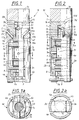
- the tilting device (10) shown in FIGS. 1 and 2 is exemplary as a tilting mirror with sensor system (9a) executed.
- the tilting device (10) shown consists in essentially from an upper tilting body (14), which itself relative to a lower base body (4) by one before constructively set amount. Between These two bodies (4, 14) have a bearing (3a, 3b, 3c, 3d).
- the bearing (3a, 3b, 3c, 3d) between the upper tilting body (14) and the lower base body (4) takes place via four bearing balls (3a, 3b, 3c, 3d), with a bearing ball (3a) fixed a receptacle (11) provided for this purpose on a cylindrical one Elevation (12) in the upper part of the base body (4) is connected and the three other bearing balls (3a, 3b, 3c) can move smoothly on it.
- the cylindrical Elevation (12) in the upper part of the base body (4) protrudes far into the larger opening (15) in the lower part (2) of the tilting body (14) into it.
- the tilting device (10) in any spatial Location (this is the spatial location or orientation of the Base body meant) can be used, the Center of gravity of the tilting body (14) and rigid with it connected parts in the fulcrum.
- the focus is on Pivot point, this has the decisive advantage that the once set spatial relation between tilting body (14) and base body (4) to each other without further energy expenditure remains. So you only need one Energy expenditure if you consider the spatial position between the tilting body (14) and base body (4) wants to change. But is this location of the tilting body (14) relative to the base body (4), see above no further energy is required around the tilting body (14) to keep in this position relative to the base body (4).
- this advantage of the storage according to the invention lowers the Energy consumption of the tilting device (10) is enormous and ensures to ensure that no heat build-up arises from waste heat. This is a big problem with a large number of those on the market Tilting mirror, especially if a small size is desired becomes.
- the movable tilting body (14) has downward, as well the fixed parts (4a and 4b) of the base body (4), the shape a slotted tube sleeve (see Figures 1 and 2).
- At the top Part (1) of the tilting body (14) has a mirror body (1) with mirrored surface (1a), which is fixed to the bearing body (2) attached under the mirror body (1) of the tilting body (14) is connected (e.g. glued).
- Two lateral elements extend on this bearing body (2) relatively thin apron body (2a, 2b) laterally downwards, which as a fastening body for one firmly attached to them attached first magnetic holder (7) made of titanium.
- this magnet holder (7) is a permanent magnet (7c) held that its magnetic poles (north and south poles) too the two coils (5, 6) point out.
- the first permanent magnet (7c) which part of the biaxial drive system is between the two attach fixed coils (5, 6) to the base body (4).
- a second permanent magnet (8) attached (see also Figures 3a and 3b), the Attachment by gluing the two bodies (2a, 2b; 8) with each other.
- the sleeve-shaped one makes it possible Shape of the tilting body (14) in its lower area, the second permanent magnet (8), which is part of the sensor system (see Figures 3a and 3b) on the movable tilting body (14) to be firmly attached (e.g. glued on).
- FIGS. 1 and 2 the magnetic north pole of the magnet below, and the apron body (2a, 2b) of the tilting body (14) are in this north-south extension direction arranged.
- Figure 1a shows the exact one Shape of the upper permanent magnet (7c) again clearly shown.
- the permanent magnet (7c) is supported by a magnet (7), which is a substantially cylindrical tubular Shape with different wall thicknesses with a circular middle opening for receiving the permanent magnet (7c) owns.
- the storage body (2) has two in its lower part inclined surfaces (2a, 2b) which are inclined obliquely upwards and each on the opposite sides of the storage body (2). In these inclined surfaces (2c, 2d) there is a recess in each one Permanent magnet (16a, 16b) is embedded. These two permanent magnets (16a, 16b) act with two obliquely arranged soft magnetic plates (17a, 17b) in the upper part of the Base body (4), which they are exactly opposite, such together that the tilting body (14) and the base body (4) are magnetically biased towards each other and the four Bearing balls (3a, 3b, 3c, 3d) are pressed together.
- the base body (4) is essentially a hollow cylinder body, which on both sides recesses (18a), (18b in the figure not shown) for receiving the apron body (2a, 2b) of the Tilting body (14) has. At the top of the base body (4) he has an upper cap (4c), from which in the Central axis, the cylindrical elevation (12) with its recording (11) protrudes for the bearing ball (3a).
- the inclined surfaces (17a, 17b) on the base body (4) exist made of a magnetic material (e.g. soft iron) and care together with the permanent magnets (16a, 16b) of the tilting body (14) for a magnetic bias between the base body (4) and Tilt body (14). Both magnetic poles of the permanent magnet (16a, 16b) lie opposite the inclined surfaces (17a, 17b), see above that by the magnetic circuit that can be achieved results in a greater holding force.
- a magnetic material e.g. soft iron
- a retaining web (5a) (preferably made of a magnetizable Material such as Soft iron) around which the turns a first coil (5) are wound.
- This first coil (5) lies in the tilting device (10) above that on the tilting body (14) attached first permanent magnet (7c) and serves together with this permanent magnet (7c) as a drive device for uniaxial relative adjustment between base body (4) and Tilt body (14).
- Their windings are perpendicular to the north-south axis of the magnet (7c).
- another retaining web (6a) (preferably from a magnetizable material such as Soft iron) around which the Windings of a second coil (6) wound transversely to the first are.
- This coil (6) serves together with the permanent magnet (7c) as a drive device for the second uniaxial relative adjustment between base body (4) and tilting body (14). Also their windings are perpendicular to the north-south axis of the magnet (7c) oriented, but are also perpendicular to the Windings of the first coil (5) oriented.
- both coils (5, 6) in terms of their winding directions) are oriented transversely to one another.
- the sensor system is used to determine the exact position of the Tilting device (10).
- several (at least one sensor (9a) for each Hall sensor (9a) attached which depending on the tilt angle of the tilting body (14) relative to the base body (4) give different voltage.
- the Hall sensors (9a) evaluate the Direction of the magnetic field of the permanent magnet (8).
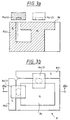
- Form of the permanent magnet (8) of the sensor system is in particular off Figures 3a and 3b can be seen.
- the permanent magnet (8) is like this constructed a relatively large square north pole (8a) made of a suitable material that is so large that at the maximum permissible deflection of the tilting body (14) Hall sensor (9a (1), 9a (2)) of a tilt axis never to the middle of the magnetic north pole body (8a).
- the magnetic The south pole is so raised laterally that between the Surface of the magnetic north pole part (8a ') and magnetic south pole part (8b1 ', 8b2') each gives a gap.
- the two Hall sensors (9a (1), 9a (2)) are arranged.
- the Hall sensors (9a (1), 9a (2)) have thereby maximum sensitivity for tilting movements of the Tilting body (14) on which the permanent magnet (8) is attached is.
- the sensor system has a signal line to a computer system or to a control system for the coil current two coils (5, 6), so that if the position of the Tilting body (14) relative to a desired position Controls of the coils (5, 6) are readjusted as long as until the tilting body (10) has assumed the desired position.
- the two coils (5, 6) and the one with the Hall sensors (9a) equipped circuit board (9) are attached to the fixed parts (4a, 4b) of the base body (4) rigidly attached (e.g. glued in) before looking at the outer parts (4a, 4b) of the base body (4) rigidly attached (e.g. gluing during assembly).
- the preferred area of use for the tilting device is Use as a tilting mirror. These can be one or two axes be. Although currently on the market one and two-axis Tilt mirrors are available, so they have the disadvantage that they don't meet one or more of the above requirements able to fulfill.
- the tilting device according to the invention can in particular as small two-axis tilting mirror can be used, its size in the mirror plane is not bigger than the mirror itself, the mirror surface (1a) typically being a circle of 3-12 mm Diameter is. In doing so, two are perpendicular to each other stationary axes a tilting movement of at least ⁇ 1.5 ° to 3 ° reached, the angular resolution within approximately half possible tilt angle range 2048 individual steps reached ( ⁇ 0.8 ° at tilt angle ⁇ 1.5 °).
- a permanently installed sensor system (9) available, the actual position of the tilting body (14) relative to the base body (4) determined.
- the tilting device (10) is as Module built to a segmented from several modules to be able to put together larger mirrors. Besides, that is Tilting device (14) suitable for inexpensive mass production.
Abstract
Description
Die Erfindung betrifft ein Verfahren zur Lagerung einer Kippvorrichtung gemäß dem Oberbegriff des ersten Patentanspruchs sowie eine Kippvorrichtung, welche nach diesem Verfahren arbeitet.The invention relates to a method for storing a Tilting device according to the preamble of the first Claim and a tilting device, which according to this Process works.
Derartige Kippvorrichtungen sind aus dem bekannten Stand der Technik reichlich bekannt. Sie dienen dazu, einen auf sie auffallenden Lichtstrahl definiert um einen gewissen Winkel abzulenken. Man unterscheidet insbesondere 1-achsige und 2-achsige Kippspiegel.Such tilting devices are known from the prior art Technology well known. They serve one on them striking light beam defined by a certain angle distract. One differentiates in particular 1-axis and 2-axis tilting mirror.
Während einachsige Kippspiegel heute ein marktübliches Produkt mit großer technischer Variation sind, sind zweiachsige Kippspiegel, welche heute zwar ebenfalls Stand der Technik und auf dem Markt erhältlich sind, noch bedeutenden technischen Einschränkungen unterworfen. Diese Einschränkungen sind insbesondere:
- begrenzter Kippwinkel um die x- bzw. y-Achse um normalerweise einen Winkel kleiner als 1°;
- eingeschränkte Baugröße (Dabei erfordern gewisse Kippwinkel eine gewisse Mindestbaugröße oder auch maximale Baugröße, was jeweils störend ist.);
- Baugröße der Kippspiegelanordnung deutlich größer als Spiegelfläche, insbesondere hinter der Spiegelfläche bei kleinen Kippspiegeln (d.h. mit den Spiegeln nach dem bekannten Stand der Technik sind keine hohen Packungsdichten erreichbar); oder
- komplizierte Herstellungstechnik der bekannten zweiachsigen Kippspiegel.
- limited tilt angle around the x or y axis by normally an angle less than 1 °;
- restricted size (certain tilt angles require a certain minimum size or maximum size, which is bothersome);
- Size of the tilting mirror arrangement is significantly larger than the mirror area, in particular behind the mirror area in the case of small tilting mirrors (ie high packing densities cannot be achieved with the mirrors according to the known prior art); or
- complicated manufacturing technique of the well-known biaxial tilting mirror.
Aus der US-PS 4,708,420 ist eine Kippspiegelanordnung bekannt, welche zum Scannen verwendet wird. Dabei ist der Scan-Spiegel über Biegegelenke mit piezokeramischen Antriebselementen verbunden, welche parallel zur Spiegeloberfläche angeordnet sind. Damit die piezokeramischen Antriebselemente den Spiegel um einen großen Winkel kippen können, muß diese Anordnung sehr groß sein. Dies resultiert aus der geringen Verbiegung der piezokeramischen Antriebselemente, welche proportional zur Länge dieser Elemente ist. Damit ist diese Anordnung nicht dazu geeignet, kleine Spiegel um einen großen Winkelbereich zu kippen, wenn der Antriebsmechanismus hinter dem Kippspiegel auf die Dimension der Spiegelfläche begrenzt sein soll.A tilting mirror arrangement is known from US Pat. No. 4,708,420, which is used for scanning. Here is the scan mirror via flexible joints with piezoceramic drive elements connected, which is arranged parallel to the mirror surface are. So that the piezoceramic drive elements the mirror This arrangement must be able to tip over a large angle be great. This results from the slight bending of the Piezoceramic drive elements, which are proportional to the Length of these elements is. So this arrangement is not for that suitable for small mirrors around a large angular range tilt when the drive mechanism behind the tilt mirror the dimension of the mirror surface should be limited.
Aus der US-PS 4,383,763 ist eine Kippspiegelanordnung bekannt, bei welchem der Spiegel auf einem Kipp-Punkt gelagert ist und über piezoelektrische Keramiken bewegt wird. Auch hier müssen die Dimensionen des Spiegels sehr groß sein, wenn der Kippspiegel um mindestens 1° gekippt werden soll.A tilting mirror arrangement is known from US Pat. No. 4,383,763, in which the mirror is mounted on a tilt point and is moved over piezoelectric ceramics. Here too the dimensions of the mirror will be very large if the tilting mirror should be tilted by at least 1 °.
Aus der US-PS 4,660,941 ist eine Kippspiegelhalterung bekannt, bei welchem die Kippspiegelbewegung durch piezoelektrische Elemente erreicht wird und die piezoelektrischen Elemente wirken dabei über Hebel auf den Spiegel. Auch diese Anordnung ist nicht dazu geeignet, einen kleinen Spiegel um mindestens 1° zu kippen.A tilting mirror holder is known from US Pat. No. 4,660,941, in which the tilting mirror movement by piezoelectric Elements is achieved and the piezoelectric elements act on the mirror via levers. This arrangement too is not suitable for a small mirror by at least 1 ° to tip.
Aus der US-PS 5,170,277 ist ein piezoelektrischer Strahlreflektor bekannt, bei welchem der Spiegelkörper direkt auf dem piezoelektrischen Element befestigt ist. Dies hat den Nachteil, daß der Spiegel bei einer Kippung keinen definierten Drehpunkt besitzt.A piezoelectric beam reflector is known from US Pat. No. 5,170,277 known in which the mirror body directly on the piezoelectric element is attached. This has the disadvantage that the mirror does not have a defined pivot point when tilted owns.
Aus der US-PS 4,691,212 ist ein piezoelektrischer Strahlreflektor bekannt, welcher in einer Scananordnung verwendet wird. Der Nachteil dieser Anordnung ist, daß ein bestimmter Ablenkwinkel nicht starr gehalten werden kann, wenn der Drehpunkt fest liegen soll.A piezoelectric beam reflector is known from US Pat. No. 4,691,212 known, which is used in a scanning arrangement becomes. The disadvantage of this arrangement is that a certain one Deflection angle cannot be kept rigid when the fulcrum should be firm.
Aus der DE 195 19 161 ist eine piezoelektrische Abtastvorrichtung bekannt, bei welcher ein Paar von piezoelektrischen Plattenelementen, die sich transversal zu einer Basis erstrecken, an einem Ende auf ein Aufbauelement gemeinsam so einwirken, daß dieses Aufbauelement kippt. Es sind somit für eine Kippachse zwei sich zusammen bewegende Plattenelemente notwendig, welche sich zur Kippung entgegengesetzt bewegen müssen. Die Plattenelemente greifen dazu an unterschiedlichen Stellen eines Stabes unterhalb des Aufbauelementes an. Für eine Kippung um eine dazu senkrechte Kippachse sind zwei weitere Plattenelemente notwendig.DE 195 19 161 describes a piezoelectric scanning device known in which a pair of piezoelectric Plate elements that are transverse to a base extend at one end to a building element together so act that this structural element tilts. It is therefore for a tilt axis two plate elements moving together necessary, which move opposite to the tilt have to. The plate elements use different ones Place a rod below the construction element. For one Tilting about a vertical tilt axis are two more Plate elements necessary.
Es ist die Aufgabe der Erfindung, eine Kippvorrichtung zu schaffen, bei welcher eine eingestellte Auslenkung ohne Energiezufuhr von sich aus erhalten bleibt.It is the object of the invention to provide a tilting device create in which a set deflection without Energy supply on its own is maintained.
Diese Aufgabe wird erfindungsgemäß durch ein Verfahren nach dem kennzeichnenden Teil des ersten Patentanspruches sowie eine Kippvorrichtung nach dem kennzeichnenden Teil des dritten Patentanspruches gelöst.This object is achieved by a method according to the characterizing part of the first claim and a Tilting device according to the characteristic part of the third Claim resolved.
Das erfindungsgemäße Verfahren zur Lagerung einer Kippvorrichtung ermöglicht eine Kippung um mindestens eine Achse und verwendet einen Kippkörper, einen Basiskörper und eine zwischen diesen beiden Körpern liegenden Lagerung. Dabei liegt der Schwerpunkt des Kippkörpers im Drehpunkt der Lagerung. Dies hat den großen Vorteil, daß man nur Energie für eine Lageänderung aufbringen muß. Die sich dann einstellende Kipplage bleibt dann ohne weiteren Energieaufwand bestehen.The inventive method for storing a Tilting device enables tilting by at least one Axis and uses a tilt body, a base body and a bearing lying between these two bodies. Here the center of gravity of the tilting body lies in the fulcrum of the Storage. This has the great advantage that you only have energy for must bring up a change of position. The one that then arises The tilt position then remains without further energy expenditure.
Um keine Schwingungen im System zu haben und um eine einfach herzustellende Kippvorrichtung zu erhalten, ist es vorteilhaft, wenn bei einer Kippbewegung lediglich der Kippkörper mit den an ihm befestigten Teilen bewegt wird.In order to have no vibrations in the system and just one To obtain the tilting device to be manufactured, it is advantageous if only the tilting body with the on during a tilting movement parts attached to it are moved.
Die sich aus obiger Forderung ergebende Kippvorrichtung, welche eine Kippung um mindestens eine Achse ermöglicht, besitzt einen Kippkörper, einen Basiskörper und eine zwischen diesen beiden Körpern liegende Lagerung. Die Kippvorrichtung zeichnet sich erfindungsgemäß dadurch aus, daß ein erster Teil des Kippkörpers oberhalb des Drehpunktes angeordnet ist, daß ein zweiter Teil des Kippkörpers unterhalb des Drehpunktes angeordnet ist und daß das Gewicht des ersten Teils des Kippkörpers und das Gewicht des zweiten Teils des Kippkörpers einander entsprechend sind. Damit liegt aber genau der Schwerpunkt des Kippkörpers im Drehpunkt der Lagerung.The tilting device resulting from the above requirement, which tilting around at least one axis has one Tilt body, a base body and one between these two Bodies lying down. The tilting device stands out according to the invention in that a first part of the tilting body is arranged above the fulcrum that a second part of the tilting body below the pivot point is arranged and that the weight of the first part of the tilting body and the weight of the second part of the tilting body correspond to each other. But that is exactly the focus of the tilting body at the pivot point of the bearing.
Es ist vorteilhaft, wenn zur Lagerung vier runde Lagerkörper verwendet werden. Unterhalb des Kippkörpers können dabei achssymmetrisch drei der Lagerkörper in einer Ebene angeordnet sein und auf dem Basiskörper zentral eine Kugel. Lagert man die eine Kugel in den drei anderen Lagerkörpern, so erhält man eine stabile sichere Lagerung. Der zentrale Lagerkörper muß eine Kugel sein, während die drei anderen Lagerkörper Kugeln oder Rundzylinder sein können.It is advantageous if four round bearing bodies for storage be used. Below the tilting body can axially symmetrically arranged three of the bearing body in one plane be and a ball centrally on the base body. If you store them a ball in the three other bearing bodies, you get one stable safe storage. The central bearing body must be one Be bullet while the other three bearing bodies are bullets or Can be round cylinders.
Vorteilhafterweise ist der Basiskörper mit dem Kippkörper magnetisch vorgespannt, so daß bei einer Schräglage sich die beiden Körper nicht durch den Einfluß der Schwerkraft voneinander trennen.The base body with the tilting body is advantageous magnetically biased so that at an inclined position neither body by the influence of gravity separate from each other.
Es ist vorteilhaft, wenn in der Kippvorrichtung eine Antriebsvorrichtung eingebaut ist. Dies ist insbesondere dann der Fall, wenn man von der Kippvorrichtung kontrollierte Bewegungen erwartet (z.B. für eine Lichtstrahlablenkung, eine Bewegung eines auf der Kippvorrichtung angebrachten Lasers, usw.). Die Antriebsvorrichtung für eine Achse ist dabei vorteilhafter weise aus einer Spule am Basiskörper und einem Magneten am Kippkörper aufgebaut. Dabei ist es vorteilhaft, wenn der Magnet ein Dauermagnet ist.It is advantageous if a drive device in the tilting device is installed. This is particularly the case if you have movements controlled by the tilting device expected (e.g. for a light beam deflection, a movement a laser attached to the tilting device, etc.). The Drive device for an axis is more advantageous example from a coil on the base body and a magnet on Tilt body built. It is advantageous if the magnet is a permanent magnet.
Zur genauen Ermittlung der Kippung ist es vorteilhaft, wenn in der Kippvorrichtung selbst ein Positionsmeßsystem enthalten ist. Dieses Positionsmeßsystem kann vorteilhafter weise aus mindestens einem Hallsensor und mindestens einem Dauermagnet aufgebaut sein. Dabei ist es vorteilhaft, wenn der Dauermagnet am Kippkörper befestigt ist. For the exact determination of the tilt, it is advantageous if in the tilting device itself contain a position measuring system is. This position measuring system can advantageously from at least one Hall sensor and at least one permanent magnet be constructed. It is advantageous if the permanent magnet is attached to the tilting body.
Die erfindungsgemäße Kippvorrichtung eignet sich für alle Anwendungen, bei welchen es zumindest auf eine einachsige Bewegung über einen relativ kleinen, jedoch 1° überschreitenden, Kippwinkel (< 10°, vorteilhafterweise < 5°) bei relativ hohen Kippfrequenzen ankommt. Die Anwendungen umfassen Abtastungen, Belichtungen, Materialabtragungen, usw..The tilting device according to the invention is suitable for everyone Applications in which it is at least uniaxial Movement over a relatively small, but exceeding 1 °, Tilt angle (<10 °, advantageously <5 °) at relatively high tipping frequencies arrives. The applications include Scans, exposures, material removal, etc.
Insbesondere kann man mit der erfindungsgemäßen Kippvorrichtung große Segmentarrays aufbauen, welche aus einer flächenhaften Anordnung von vielen der erfindungsgemäßen Kippvorrichtung bestehen, da der Antriebsmechanismus vollständig unterhalb der zu kippenden Fläche angeordnet ist.In particular, you can with the tilting device according to the invention build up large segment arrays, which consist of an areal Arrangement of many of the tilting device according to the invention exist because the drive mechanism is completely below the is arranged to tilt surface.
Auf der zu kippenden Fläche können dabei sowohl passive Bauteile (z.B. Spiegelflächen, usw.) als auch aktive Bauteile (z.B. Laserdioden) angeordnet sein.On the surface to be tilted, both passive and Components (e.g. mirror surfaces, etc.) as well as active components (e.g. laser diodes).
Die Erfindung wird im folgenden in beispielhafter Weise anhand von Zeichnungen erläutert, wobei weitere wesentliche Merkmale sowie dem besseren Verständnis dienende Erläuterungen und Ausgestaltungsmöglichkeiten des Erfindungsgedankens beschrieben sind.The invention is described below by way of example of drawings explained, with other essential features and explanations for better understanding and Design options of the inventive concept described are.
Dabei zeigen:
Figur 1- die erfindungsgemäße Kippvorrichtung in einem seitlichen Teilschnitt;
Figur 1a- einen Schnitt in der in
Figur 1 angegebenen Ebene Ia; Figur 2- die erfindungsgemäße Kippvorrichtung aus Figur 1 in einem weiteren seitlichen Teilschnitt, welcher senkrecht zum seitlichen Teilschnitt aus der Figur 1 steht;
Figur 2a- einen Schnitt in der in Fig. 2 angegebenen Ebene IIa;
Figur 3a- das Sensorsystem in seitlicher Ansicht; und
Figur 3b- das
Sensorsystem aus Figur 3a in Aufsicht.
- Figure 1
- the tilting device according to the invention in a lateral partial section;
- Figure 1a
- a section in the plane indicated in Figure 1a;
- Figure 2
- the tilting device according to the invention from Figure 1 in a further lateral partial section, which is perpendicular to the lateral partial section from Figure 1;
- Figure 2a
- a section in the plane indicated in Figure 2aa.
- Figure 3a
- the sensor system in a side view; and
- Figure 3b
- the sensor system of Figure 3a in supervision.
Die in der Figur 1 und 2 dargestellte Kippvorrichtung (10) ist beispielhaft als ein Kippspiegel mit Sensorsystem (9a) ausgeführt. Die dargestellte Kippvorrichtung (10) besteht im wesentlichen aus einem oberen Kippkörper (14), welcher sich relativ zu einem unteren Basiskörper (4) um einen vorher konstruktiv festgelegten Betrag schräg stellen kann. Zwischen diesen beiden Körpern (4, 14) befindet sich eine Lagerung (3a, 3b, 3c, 3d).The tilting device (10) shown in FIGS. 1 and 2 is exemplary as a tilting mirror with sensor system (9a) executed. The tilting device (10) shown consists in essentially from an upper tilting body (14), which itself relative to a lower base body (4) by one before constructively set amount. Between These two bodies (4, 14) have a bearing (3a, 3b, 3c, 3d).
Die Lagerung (3a, 3b, 3c, 3d) zwischen dem oberen Kippkörper (14) und dem unteren Basiskörper (4) erfolgt über vier Lagerkugeln (3a, 3b, 3c, 3d), wobei eine Lagerkugel (3a) fest mit einer dazu vorgesehenen Aufnahme (11) auf einer zylinderförmigen Erhebung (12) im oberen Teil des Basiskörpers (4) verbunden ist und die drei anderen Lagerkugeln (3a, 3b, 3c) sich auf ihr gleitend bewegen können. Die zylinderförmige Erhebung (12) im oberen Teil des Basiskörper (4) ragt dabei weit in die größere Öffnung (15) im unteren Teil (2) des Kippkörpers (14) hinein.The bearing (3a, 3b, 3c, 3d) between the upper tilting body (14) and the lower base body (4) takes place via four bearing balls (3a, 3b, 3c, 3d), with a bearing ball (3a) fixed a receptacle (11) provided for this purpose on a cylindrical one Elevation (12) in the upper part of the base body (4) is connected and the three other bearing balls (3a, 3b, 3c) can move smoothly on it. The cylindrical Elevation (12) in the upper part of the base body (4) protrudes far into the larger opening (15) in the lower part (2) of the tilting body (14) into it.
Für die drei oberen Lagerungskugeln (3a, 3b, 3c) sind entsprechende Aufnahmen (13b, 13c, 13d) im unteren Teil (2) des Kippkörpers (14) in einer dazu vorgesehenen größeren Öffnung (15) angebracht, in welchen die drei oberen Lagerungskugeln (3a, 3b, 3c) befestigt sind.For the three upper bearing balls (3a, 3b, 3c) are corresponding recordings (13b, 13c, 13d) in the lower part (2) of the Tilting body (14) in a larger opening provided for this purpose (15) attached, in which the three upper bearing balls (3a, 3b, 3c) are attached.
Durch die exakte Kugelform und die drei Auflagepunkte der oberen Lagerkugeln (3a, 3b, 3c) auf der unteren Lagerkugel (3a) ist somit für alle Achsen derselbe, feste Drehpunkt im Mittelpunkt der unteren Lagerkugel (3a) vorgegeben.Due to the exact spherical shape and the three support points of the upper bearing balls (3a, 3b, 3c) on the lower bearing ball (3a) the same, fixed pivot point is the focus for all axes the lower bearing ball (3a).
Damit die Kippvorrichtung (10) in jeder beliebigen räumlichen Lage (damit ist die räumliche Lage bzw. Orientierung des Basiskörpers gemeint) verwendet werden kann, liegt der Schwerpunkt des Kippkörpers (14) und der mit ihm starr verbundenen Teile im Drehpunkt. Liegt der Schwerpunkt im Drehpunkt, so hat dies den entscheidenden Vorteil, daß die einmal eingestellte räumliche Relation zwischen Kippkörper (14) und Basiskörper (4) zueinander ohne weiteren Energieaufwand bestehen bleibt. Man braucht also lediglich einen Energieaufwand, wenn man die räumliche Lage zwischen Kippkörper (14) und Basiskörper (4) verändern will. Ist aber diese Lage des Kippkörpers (14) relativ zum Basiskörper (4) erreicht, so bedarf es keines weiteren Energieaufwandes um den Kippkörper (14) in dieser Position relativ zum Basiskörper (4) zu halten.So that the tilting device (10) in any spatial Location (this is the spatial location or orientation of the Base body meant) can be used, the Center of gravity of the tilting body (14) and rigid with it connected parts in the fulcrum. The focus is on Pivot point, this has the decisive advantage that the once set spatial relation between tilting body (14) and base body (4) to each other without further energy expenditure remains. So you only need one Energy expenditure if you consider the spatial position between the tilting body (14) and base body (4) wants to change. But is this location of the tilting body (14) relative to the base body (4), see above no further energy is required around the tilting body (14) to keep in this position relative to the base body (4).
Dieser Vorteil der erfindungsgemäßen Lagerung senkt aber den Energieverbrauch der Kippvorrichtung (10) enorm und sorgt dafür, daß kein Hitzestau durch Abwärme entsteht. Dies ist ein großes Problem bei einer Vielzahl der am Markt angebotenen Kippspiegel, insbesondere wenn eine kleine Baugröße angestrebt wird.However, this advantage of the storage according to the invention lowers the Energy consumption of the tilting device (10) is enormous and ensures to ensure that no heat build-up arises from waste heat. This is a big problem with a large number of those on the market Tilting mirror, especially if a small size is desired becomes.
Der bewegliche Kippkörper (14) hat nach unten hin, ebenso wie die festen Teile (4a und 4b) des Basiskörpers (4), die Form einer geschlitzten Rohrhülse (siehe Figur 1 und 2). Im oberen Teil (1) des Kippkörper (14) besitzt dieser einen Spiegelkörper (1) mit verspiegelter Oberfläche (1a), welcher fest mit dem unter dem Spiegelkörper (1) angebrachten Lagerungskörper (2) des Kippkörpers (14) verbunden ist (z.B. angeklebt).The movable tilting body (14) has downward, as well the fixed parts (4a and 4b) of the base body (4), the shape a slotted tube sleeve (see Figures 1 and 2). At the top Part (1) of the tilting body (14) has a mirror body (1) with mirrored surface (1a), which is fixed to the bearing body (2) attached under the mirror body (1) of the tilting body (14) is connected (e.g. glued).
An diesem Lagerungskörper (2) erstrecken sich zwei seitliche relativ dünne Schürzenkörper (2a, 2b) seitlich nach unten, welche als Befestigungskörper für einen an ihnen fest angebrachten ersten Magnethalter (7) aus Titan dienen. In diesem Magnethalter (7) ist ein Permanentmagnet (7c) so gehalten, daß seine magnetischen Pole (Nord- und Süd-Pol) zu den beiden Spulen (5, 6) hin weisen. Durch die rohrhülsenförmige Form des Kippkörpers (14) im seinem unteren Teil ist es möglich, den ersten Dauermagneten (7c), welcher Teil des zweiachsigen Antriebssystems ist, zwischen den beiden feststehenden Spulen (5, 6) am Basiskörper (4) anzubringen. Zur Fixierung des Magnethalters (7) mit dem Permanentmagneten (7c) des Antriebssystems an dem Schürzenkörper (2a, 2b) ist jeweils zu beiden Seiten ein Stift (7a, 7b) in jeweils einer Öffnung des Schürzenkörpers (2a, 2b) und des Magnethalters (7) angebracht, wobei dieser Stift (7a, 7b) in den beiden Öffnungen eingeklebt ist. Selbstverständlich wäre aber auch jede andere Art der sicheren Befestigung an dieser Stelle anwendbar.Two lateral elements extend on this bearing body (2) relatively thin apron body (2a, 2b) laterally downwards, which as a fastening body for one firmly attached to them attached first magnetic holder (7) made of titanium. In this magnet holder (7) is a permanent magnet (7c) held that its magnetic poles (north and south poles) too the two coils (5, 6) point out. Through the tubular sleeve It is the shape of the tilting body (14) in its lower part possible the first permanent magnet (7c), which part of the biaxial drive system is between the two attach fixed coils (5, 6) to the base body (4). For Fixing the magnet holder (7) with the permanent magnet (7c) of the drive system on the apron body (2a, 2b) is in each case on both sides a pin (7a, 7b) in an opening of the apron body (2a, 2b) and the magnet holder (7) attached, this pin (7a, 7b) in the two openings is glued in. Of course, any other would also be Type of secure attachment applicable at this point.
Am Ende der Schürzenkörper (2a, 2b) ist ein zweiter Dauermagnet (8) angebracht (siehe auch Figuren 3a und 3b), wobei die Anbringung durch eine Verklebung der beiden Körper (2a, 2b; 8) miteinander erfolgt. Auch hier ermöglicht es die hülsenförmige Gestalt des Kippkörpers (14) in seinem unteren Bereich, den zweiten Dauermagneten (8), welcher einen Teil des Sensorsystems (siehe Figuren 3a und 3b) darstellt, am beweglichen Kippkörper (14) fest anzubringen (z.B. anzukleben).At the end of the apron body (2a, 2b) is a second permanent magnet (8) attached (see also Figures 3a and 3b), the Attachment by gluing the two bodies (2a, 2b; 8) with each other. Here, too, the sleeve-shaped one makes it possible Shape of the tilting body (14) in its lower area, the second permanent magnet (8), which is part of the sensor system (see Figures 3a and 3b) on the movable tilting body (14) to be firmly attached (e.g. glued on).
In dem in den Figuren 1 und 2 dargestellten Beispiel liegt der magnetische Nordpol des Magneten unten, und die Schürzenkörper (2a, 2b) des Kippkörpers (14) sind in dieser Nord-Süd-Erstreckungsrichtung angeordnet. In der Figur 1a ist die genaue Form des oberen Dauermagneten (7c) nochmals deutlich dargestellt. Der Dauermagnet (7c) wird von einem Magnetträger (7) gehalten, welcher eine im wesentlichen zylinderrohrförmige Gestalt mit unterschiedlichen Wanddicken mit einer kreisrunden mittleren Öffnung zur Aufnahme des Permanentmagneten (7c) besitzt.In the example shown in FIGS. 1 and 2, the magnetic north pole of the magnet below, and the apron body (2a, 2b) of the tilting body (14) are in this north-south extension direction arranged. Figure 1a shows the exact one Shape of the upper permanent magnet (7c) again clearly shown. The permanent magnet (7c) is supported by a magnet (7), which is a substantially cylindrical tubular Shape with different wall thicknesses with a circular middle opening for receiving the permanent magnet (7c) owns.
Der Lagerungskörper (2) besitzt in seinem unteren Teil zwei schräge Flächen (2a, 2b), welche nach schräg oben geneigt sind und sich jeweils auf den gegenüberliegenden Seiten des Lagerungskörpers (2) befinden. In diesen Schrägflächen (2c, 2d) befindet sich jeweils eine Ausnehmung, in welche jeweils ein Dauermagnet (16a, 16b) eingelassen ist. Diese zwei Dauermagnete (16a, 16b) wirken mit zwei schräg angeordneten weichmagnetischen Platten (17a, 17b) im oberen Teil des Basiskörpers (4), welchen sie exakt gegenüberliegen, derart zusammen, daß der Kippkörper (14) und der Basiskörper (4) zueinander magnetisch vorgespannt sind und die vier Lagerungskugeln (3a, 3b, 3c, 3d) aufeinandergepreßt werden. Dadurch ist sichergestellt, daß der bewegliche Kippkörper (14) mit seinen drei Lagerungskugeln (3b, 3c, 3d) auf der Lagerungskugel (3a) des Basiskörpers (4) aufliegt und außerdem ein zusätzlicher Schutz der Kippvorrichtung (10) vor einem Verdrehen um die z-Achse (zwei rotatorische Freiheitsgrade) vorhanden ist.The storage body (2) has two in its lower part inclined surfaces (2a, 2b) which are inclined obliquely upwards and each on the opposite sides of the storage body (2). In these inclined surfaces (2c, 2d) there is a recess in each one Permanent magnet (16a, 16b) is embedded. These two permanent magnets (16a, 16b) act with two obliquely arranged soft magnetic plates (17a, 17b) in the upper part of the Base body (4), which they are exactly opposite, such together that the tilting body (14) and the base body (4) are magnetically biased towards each other and the four Bearing balls (3a, 3b, 3c, 3d) are pressed together. This ensures that the movable tilting body (14) with its three bearing balls (3b, 3c, 3d) on the Bearing ball (3a) of the base body (4) rests and also an additional protection of the tilting device (10) from one Turning around the z-axis (two rotational degrees of freedom) is available.
Der Basiskörper (4) ist im wesentlichen ein Hohlzylinderkörper, welcher zu beiden Seiten Ausnehmungen (18a), (18b in der Figur nicht dargestellt) zur Aufnahme der Schürzenkörper (2a, 2b) des Kippkörpers (14) besitzt. Am oberen Ende des Basiskörpers (4) besitzt er eine obere Verschlußkappe (4c), aus welcher in der Mittelachse die zylinderförmigen Erhebung (12) mit ihrer Aufnahme (11) für die Lagerkugel (3a) hervorragt. Seitlich von dieser Erhebung (12) sind im äußeren Bereich der oberen Verschlußkappe (4c) zwei sich gegenüberliegende schräg nach oben verlaufende Aufsätze (4e, 4f) vorhanden, deren Schräge mit der Schräge der korrespondierenden gegenüberliegenden Schrägflächen (2c, 2d) an dem Kippkörper (14) im nicht ausgelenkten Zustand der Kippvorrichtung (10) parallel verläuft.The base body (4) is essentially a hollow cylinder body, which on both sides recesses (18a), (18b in the figure not shown) for receiving the apron body (2a, 2b) of the Tilting body (14) has. At the top of the base body (4) he has an upper cap (4c), from which in the Central axis, the cylindrical elevation (12) with its recording (11) protrudes for the bearing ball (3a). Laterally from this elevation (12) are in the outer area of the upper Closure cap (4c) obliquely after two opposite Above-running attachments (4e, 4f) are available, the slant with the slope of the corresponding opposite sloping surfaces (2c, 2d) on the tilting body (14) in the undeflected State of the tilting device (10) runs parallel.
Die zwei Dauermagnete (16a, 16b), welche mit den zwei schräg angeordneten Platten (17a, 17b) im oberen Teil des Basiskörpers (4) zusammenwirken und den Kippkörper (14) gegen den Basiskörper (4) magnetisch vorspannen (so daß die vier Lagerungskugeln (3a, 3b, 3c, 3d) aufeinandergepreßt werden), reichen je nach geforderter Anwendung des Kippspiegels manchmal nicht aus. Dies betrifft insbesondere die Stabilität der Lagerung, da diese zu schwach sein kann, und ein, wenn auch geringes, Verdrehen des Kippkörpers (14) um die z-Achse.The two permanent magnets (16a, 16b), which are inclined with the two arranged plates (17a, 17b) in the upper part of the base body (4) interact and the tilting body (14) against the base body (4) magnetically pretension (so that the four bearing balls (3a, 3b, 3c, 3d) are pressed together), are sufficient sometimes after the required use of the tilting mirror. This applies in particular to the stability of the storage, since it may be too weak, and one, if slight, Turn the tilting body (14) around the z-axis.
Das kann aber leicht behoben werden, wenn man die beiden Dauermagnete (16a, 16b) durch mindestens drei, vorteilhafterweise vier Dauermagnete (es können aber auch mehr Magnete sein) ersetzt, welche vorteilhafterweise in gleichem Abstand zueinander angeordnet sind. Auf jeden Fall müssen die Dauermagnete dann so angeordnet sein, daß sie nicht alle auf einer Linie liegen, sondern eine Fläche aufspannen (dabei müssen die Magnete nicht quadratisch angeordnet sein, sondern lediglich in einem Dreieck, Rechteck, bzw. Vieleck, wobei die Abstände der Magnete zueinander nicht gleich sein müssen).But that can easily be fixed if you look at the two Permanent magnets (16a, 16b) by at least three, advantageously four permanent magnets (but more can Magnets be replaced), which advantageously in the same Are spaced from each other. In any case, they have to Permanent magnets can then be arranged so that they are not all on lie on a line, but span a surface (thereby the magnets do not have to be arranged square, but only in a triangle, rectangle or polygon, the The distances between the magnets do not have to be the same).
Während zwei Dauermagnete (16a, 16b), wie im Beispiel dargestellt, nur um eine Achse stabilisieren können (dazu sollten sie schmal sein), ist eine gute Stabilisierung um zwei Achsen erst mit mindestens drei Magneten möglich. Mit zunehmender Anzahl der Magnete wird die Stabilität gegen Verdrehung um die z-Achse immer besser.During two permanent magnets (16a, 16b), as in the example shown, can only stabilize around an axis (see should they be narrow) is a good stabilization by two Axes only possible with at least three magnets. With increasing number of magnets will counter the stability Twisting around the z-axis is getting better.
Die Schrägflächen (17a, 17b) auf dem Basiskörper (4) bestehen aus einem magnetischen Material (z.B. Weicheisen) und sorgen zusammen mit den Dauermagneten (16a, 16b) des Kippkörpers (14) für eine magnetische Vorspannung zwischen Basiskörper (4) und Kippkörper (14). Beide magnetischen Pole der Dauermagneten (16a, 16b) liegen den Schrägflächen (17a, 17b) gegenüber, so daß sich durch den dadurch erreichbaren magnetischen Schluß eine größere Haltekraft ergibt.The inclined surfaces (17a, 17b) on the base body (4) exist made of a magnetic material (e.g. soft iron) and care together with the permanent magnets (16a, 16b) of the tilting body (14) for a magnetic bias between the base body (4) and Tilt body (14). Both magnetic poles of the permanent magnet (16a, 16b) lie opposite the inclined surfaces (17a, 17b), see above that by the magnetic circuit that can be achieved results in a greater holding force.
Unterhalb der Verschlußkappe (4c) des Basiskörpers (4) befindet sich ein Haltesteg (5a) (vorzugsweise aus einem magnetisierbaren Material wie z.B. Weicheisen), um welchen die Windungen einer ersten Spule (5) gewickelt sind. Diese erste Spule (5) liegt in der Kippvorrichtung (10) oberhalb des am Kippkörper (14) befestigten ersten Dauermagneten (7c) und dient zusammen mit diesem Dauermagneten (7c) als Antriebseinrichtung zur einachsigen Relativverstellung zwischen Basiskörper (4) und Kippkörper (14). Ihre Wicklungen sind senkrecht zur Nord-Süd-Achse des Magneten (7c) orientiert.Located below the cap (4c) of the base body (4) a retaining web (5a) (preferably made of a magnetizable Material such as Soft iron) around which the turns a first coil (5) are wound. This first coil (5) lies in the tilting device (10) above that on the tilting body (14) attached first permanent magnet (7c) and serves together with this permanent magnet (7c) as a drive device for uniaxial relative adjustment between base body (4) and Tilt body (14). Their windings are perpendicular to the north-south axis of the magnet (7c).
Unterhalb des Dauermagneten (7c) am Kippkörper (14) befindet sich ein weiterer Haltesteg (6a) (vorzugsweise aus einem magnetisierbaren Material wie z.B. Weicheisen), um welchen die Wicklungen einer zweiten Spule (6) quer zur ersten gewickelt sind. Diese Spule (6) dient zusammen mit dem Dauermagneten (7c) als Antriebseinrichtung zur zweiten einachsigen Relativverstellung zwischen Basiskörper (4) und Kippkörper (14). Auch ihre Wicklungen sind senkrecht zur Nord-Süd-Achse des Magneten (7c) orientiert, sind aber zusätzlich senkrecht zu den Wicklungen der ersten Spule (5) orientiert. Man kann auch sagen, daß beide Spulen (5, 6) (hinsichtlich ihrer Wickelrichtungen) quer zueinander orientiert sind.Located below the permanent magnet (7c) on the tilting body (14) another retaining web (6a) (preferably from a magnetizable material such as Soft iron) around which the Windings of a second coil (6) wound transversely to the first are. This coil (6) serves together with the permanent magnet (7c) as a drive device for the second uniaxial relative adjustment between base body (4) and tilting body (14). Also their windings are perpendicular to the north-south axis of the magnet (7c) oriented, but are also perpendicular to the Windings of the first coil (5) oriented. One can also say that both coils (5, 6) (in terms of their winding directions) are oriented transversely to one another.
Da die Windungen der ersten Spule (5) senkrecht auf den Windungen der zweiten Spule (6) stehen, ergibt sich bei einem Stromfluß durch die erste Spule (5) z.B. eine Drehung um die x-Achse, während ein Stromfluß in der zweiten Spule (6) eine Drehung um die dazu senkrecht stehende y-Achse bewirkt. Bin gleichzeitiger Stromfluß durch beide Spulen (5, 6) bewirkt somit eine Bewegung des Kippkörpers (14) um die x- und gleichzeitig um die y-Achse.Since the turns of the first coil (5) perpendicular to the Turns of the second coil (6), results in one Current flow through the first coil (5) e.g. a turn around that x-axis, while a current flow in the second coil (6) a Rotation around the vertical y axis. I am simultaneous current flow through both coils (5, 6) causes thus a movement of the tilting body (14) around the x and at the same time around the y axis.
Im unteren Teil des Basiskörpers (4) unterhalb des zweiten Dauermagneten (8) an den Schürzenkörpern (2a, 2b) befindet sich eine untere Verschlußkappe (4d), auf welcher eine Platine (9) mit elektronischen Bauteilen (9a) angebracht ist, welche zu einem Sensorsystem gehören (siehe auch Figuren 3a und 3b).In the lower part of the base body (4) below the second Permanent magnets (8) are located on the apron bodies (2a, 2b) a lower sealing cap (4d) on which a circuit board (9) with electronic components (9a) is attached, which too belong to a sensor system (see also FIGS. 3a and 3b).
Wird auf eine oder beide Spulen (5, 6) Strom gegeben, so wirkt im Magnetfeld des Dauermagneten (7c) auf die elektrischen Leiter eine Kraft (senkrecht zum Magnetfeld und zur Stromrichtung). Durch diese Kraft wird nun, da die Spulen (5, 6) fest mit dem Basiskörper (4) verbunden sind, der Dauermagnet (7c) abgelenkt. Dadurch bewegen sich auch alle mit ihn verbundenen Teile in einer um den Drehpunkt sphärisch verlaufenden Fläche, d.h. auch der Kippkörper (14). Durch diese Bewegung wird die verspiegelte Oberfläche (1a) auf dem Spiegelkörper (1) um den jeweiligen gewünschten Winkel um die x-, oder y-Achse oder um beide Achsen gleichzeitig gekippt.If current is applied to one or both coils (5, 6), then it acts in the magnetic field of the permanent magnet (7c) on the electrical Conduct a force (perpendicular to the magnetic field and to the current direction). With this force, now that the coils (5, 6) are permanently connected to the base body (4), the permanent magnet (7c) distracted. As a result, everyone moves with him connected parts in a sphere around the pivot point running surface, i.e. also the tilting body (14). Through this The mirrored surface (1a) moves on the Mirror body (1) around the desired angle x-, or y-axis or tilted around both axes at the same time.
Da alle oben beschriebenen Teile fest mit dem Kippkörper (14) verbunden sind, besitzt die erfindungsgemäße Kippvorrichtung nur ein in sich starres bewegtes Teil (14), welches sich relativ zu einem anderen starren Teil (4) bewegen kann. Since all the parts described above are firmly attached to the tilting body (14) are connected, has the tilting device according to the invention only a rigid moving part (14) which is can move relative to another rigid part (4).
Sämtliche Teile des Lagerungssystems, des Antriebssystems und des Positionsmeßsystems sind starr an diesen beiden Teilen befestigt und führen selber keine Eigenbewegungen aus.All parts of the storage system, the drive system and the position measuring system are rigid on these two parts attached and do not make their own movements.
Es versteht sich selbstredend, daß alle Dimensionierungen für einzelne Bauteile der Kippvorrichtung (10) so sein müssen, daß im gewünschten Auslenkwinkelbereich eine freie Bewegung des Kippkörpers (14) relativ zur Basis (4) sichergestellt ist und keines der Bauteile des Kippkörpers (14) gegen Bauteile des Basiskörpers (4) stößt. Außerdem ist bei der Dimensionierung der Antriebssysteme (Spulen (5, 6) und Dauermagnet (7c)) darauf zu achten, daß sie die zur Verstellung benötigten Kräfte erzeugen können. Bei der Auswahl der Bauteile für das Positionsmeßsystem muß darauf geachtet werden, daß die ausgewählten Positionsmeßsensoren die erforderliche Meßgenauigkeit und Auflösung haben.It goes without saying that all dimensions for individual components of the tilting device (10) must be such that a free movement of the Tilting body (14) is ensured relative to the base (4) and none of the components of the tilting body (14) against components of the Basic body (4) bumps. Also in the dimensioning the drive systems (coils (5, 6) and permanent magnet (7c)) on it to ensure that they have the forces required for adjustment can generate. When choosing the components for the Position measuring system must ensure that the selected position sensors the required Have measurement accuracy and resolution.
Das Sensorsystem dient der genauen Positionsbestimmung der Kippvorrichtung (10). In dem hier dargestellten Beispiel sind auf der Platine (9) mehrere (zumindest ein Sensor (9a) für jede Kippachse) Hallsensoren (9a) angebracht, welche je nach Kippwinkel des Kippkörpers (14) relativ zum Basiskörper (4) eine andere Spannung abgeben. Die Hallsensoren (9a) werten dabei die Richtung des Magnetfeldes des Dauermagneten (8) aus. Die Form des Dauermagneten (8) des Sensorsystems ist insbesondere aus den Figuren 3a und 3b ersichtlich. Der Dauermagnet (8) ist so konstruiert, daß er einen relativ großen quadratischen Nordpol (8a) aus einem geeigneten Material hat, welcher so groß ist, daß bei maximal zulässiger Auslenkung des Kippkörpers (14) der Hallsensor (9a(1), 9a(2)) einer Kippachse niemals bis zur Mitte des magnetischen Nordpolkörpers (8a) gelangt. Der magnetische Südpol ist seitlich so hochgeführt, daß sich zwischen der Oberfläche des magnetischen Nordpolteils (8a') und des magnetischen Südpolteils (8b1', 8b2') jeweils ein Spalt ergibt. Genau oberhalb dieser beiden Spalte (deren Orientierung senkrecht zueinander ist) sind die beiden Hallsensoren (9a(1), 9a(2)) angeordnet. Die Hallsensoren (9a(1), 9a(2)) haben dadurch eine maximale Empfindlichkeit für Kippbewegungen des Kippkörpers (14), an welchem der Dauermagnet (8) angebracht ist.The sensor system is used to determine the exact position of the Tilting device (10). In the example shown here on the board (9) several (at least one sensor (9a) for each Hall sensor (9a) attached, which depending on the tilt angle of the tilting body (14) relative to the base body (4) give different voltage. The Hall sensors (9a) evaluate the Direction of the magnetic field of the permanent magnet (8). Form of the permanent magnet (8) of the sensor system is in particular off Figures 3a and 3b can be seen. The permanent magnet (8) is like this constructed a relatively large square north pole (8a) made of a suitable material that is so large that at the maximum permissible deflection of the tilting body (14) Hall sensor (9a (1), 9a (2)) of a tilt axis never to the middle of the magnetic north pole body (8a). The magnetic The south pole is so raised laterally that between the Surface of the magnetic north pole part (8a ') and magnetic south pole part (8b1 ', 8b2') each gives a gap. Just above these two columns (their orientation perpendicular to each other) are the two Hall sensors (9a (1), 9a (2)) arranged. The Hall sensors (9a (1), 9a (2)) have thereby maximum sensitivity for tilting movements of the Tilting body (14) on which the permanent magnet (8) is attached is.
Das Sensorsystem besitzt eine Signalleitung zu einem Rechnersystem bzw. zu einem Regelungssystem für den Spulenstrom der beiden Spulen (5, 6), so daß bei einer Abweichung der Lage des Kippkörpers (14) relativ zu einer gewünschten Lage die Ansteuerungen der Spulen (5, 6) so lange nachgeregelt werden, bis der Kippkörper (10) die gewünschte Lage eingenommen hat.The sensor system has a signal line to a computer system or to a control system for the coil current two coils (5, 6), so that if the position of the Tilting body (14) relative to a desired position Controls of the coils (5, 6) are readjusted as long as until the tilting body (10) has assumed the desired position.
Die beiden Spulen (5, 6) sowie die mit den Hallsensoren (9a) bestückte Platine (9) werden an den feststehenden Teilen (4a, 4b) des Basiskörpers (4) starr befestigt (z.B. eingeklebt) bevor man die äußeren Teile (4a, 4b) des Basiskörpers (4) an diesem starr befestigt (z.B. Verklebung bei der Montage).The two coils (5, 6) and the one with the Hall sensors (9a) equipped circuit board (9) are attached to the fixed parts (4a, 4b) of the base body (4) rigidly attached (e.g. glued in) before looking at the outer parts (4a, 4b) of the base body (4) rigidly attached (e.g. gluing during assembly).
Die Erfindung betrifft eine Kippvorrichtung, welche mehreren wünschenswerten Anforderungen entspricht. Diese Anforderungen lassen sich wie folgt auflisten:
- Der mögliche Kippwinkel in einer oder zwei zueinander
senkrecht angeordneten Achsen beträgt ± 3° und mehr,
wenigstes jedoch - Der Querschnitt der Kippvorrichtung (10) ist nicht größer als die Spiegelfläche (1a), so daß mehrere Einzelspiegel nebeneinander gesetzt werden können, um z.B. einen räumlich gekrümmten Segmentspiegel aus vielen der oben beschriebenen Kippvorrichtungen (10) bauen zu können. Dies ist bei kleinen Kippwinkeln < 10° hier immer möglich.
- Der Preis liegt weit unter dem handelsüblicher Kippvorrichtungen (> 1.000.- DM), weil mit einer geringen Anzahl von leicht herzustellenden Bauteilen mit schnellen Montagetechniken gearbeitet wird.
- Die Kippvorrichtung (10) ist regelbar, was durch die Sensoren (9a) zur Ortsbestimmung sichergestellt ist.
- Die Funktion ist in jeder räumlichen Lage gewährleistet, was durch das Zusammenfallen von Drehpunkt und Schwerpunkt des Kippkörpers (14) sichergestellt ist.
- Kleiner Energieverbrauch, so daß die Leistung bei mehreren zu einem Array zusammengesetzten Kippvorrichtungen nicht zu hoch wird. Auch hier ist das Zusammenfallen von Drehpunkt und Schwerpunkt vorteilhaft.
- Aufbau der Kippvorrichtung (10) ist möglichst schwingungsfrei, so daß sich Regelkreise nicht aufschaukeln können.
- Aufbau der Kippvorrichtung ist möglichst einfach, so daß Serienfertigung möglich ist.
- The possible tilt angle in one or two mutually perpendicular axes is ± 3 ° and more, but at least 1.5 °.
- The cross section of the tilting device (10) is not larger than the mirror surface (1a), so that several individual mirrors can be placed next to one another, for example in order to be able to build a spatially curved segment mirror from many of the tilting devices (10) described above. This is always possible with small tilt angles <10 °.
- The price is far below the standard tilting devices (> 1,000.- DM), because with a small number of easily manufactured components, fast assembly techniques are used.
- The tilting device (10) can be regulated, which is ensured by the sensors (9a) for determining the location.
- The function is guaranteed in every spatial position, which is ensured by the coincidence of the pivot point and the center of gravity of the tilting body (14).
- Low energy consumption, so that the performance does not become too high when several tilting devices are combined into an array. Here, too, the pivot point and center of gravity coincide.
- The structure of the tilting device (10) is as free of vibrations as possible, so that control loops cannot build up.
- The structure of the tilting device is as simple as possible, so that series production is possible.
Das bevorzugte Einsatzgebiet der Kippvorrichtung ist die Verwendung als Kippspiegel. Diese können ein- oder zweiachsig sein. Wenngleich auf dem Markt zur Zeit ein- und zweiachsige Kippspiegel erhältlich sind, so haben sie doch den Nachteil, daß sie eine oder mehrere der oben genannten Forderungen nicht erfüllen können.The preferred area of use for the tilting device is Use as a tilting mirror. These can be one or two axes be. Although currently on the market one and two-axis Tilt mirrors are available, so they have the disadvantage that they don't meet one or more of the above requirements able to fulfill.
Die erfindungsgemäße Kippvorrichtung kann insbesondere als kleiner zweiachsiger Kippspiegel eingesetzt werden, dessen Baugröße in Spiegelebene nicht größer als der Spiegel selber ist, wobei die Spiegelfläche (1a) typisch ein Kreis von 3-12 mm Durchmesser ist. Dabei werden in zwei zueinander senkrecht stehenden Achsen eine Kippbewegung von mindestens ± 1,5° bis 3° erreicht, wobei die Winkelauflösung innerhalb ungefähr des halben möglichen Kippwinkelbereichs 2048 Einzelschritte erreicht (± 0,8° bei Kippwinkel ± 1,5°). Um die Kippvorrichtung regeln zu können, ist ein fest eingebautes Sensorsystem (9) vorhanden, das die Ist-Position des Kippkörpers (14) relativ zum Basiskörper (4) ermittelt. Die Kippvorrichtung (10) ist als Modul aufgebaut, um aus mehreren Modulen einen segmentierten größeren Spiegel zusammensetzen zu können. Außerdem ist die Kippvorrichtung (14) zur preiswerten Massenproduktion geeignet.The tilting device according to the invention can in particular as small two-axis tilting mirror can be used, its size in the mirror plane is not bigger than the mirror itself, the mirror surface (1a) typically being a circle of 3-12 mm Diameter is. In doing so, two are perpendicular to each other stationary axes a tilting movement of at least ± 1.5 ° to 3 ° reached, the angular resolution within approximately half possible tilt angle range 2048 individual steps reached (± 0.8 ° at tilt angle ± 1.5 °). To the tipping device to be able to regulate is a permanently installed sensor system (9) available, the actual position of the tilting body (14) relative to the base body (4) determined. The tilting device (10) is as Module built to a segmented from several modules to be able to put together larger mirrors. Besides, that is Tilting device (14) suitable for inexpensive mass production.
Claims (12)
Applications Claiming Priority (4)
| Application Number | Priority Date | Filing Date | Title |
|---|---|---|---|
| DE19638213 | 1996-09-19 | ||
| DE19638213 | 1996-09-19 | ||
| DE19701485A DE19701485A1 (en) | 1996-09-19 | 1997-01-17 | Method for storing a tilting device and tilting device |
| DE19701485 | 1997-01-17 |
Publications (3)
| Publication Number | Publication Date |
|---|---|
| EP0831269A2 true EP0831269A2 (en) | 1998-03-25 |
| EP0831269A3 EP0831269A3 (en) | 1998-07-08 |
| EP0831269B1 EP0831269B1 (en) | 2003-09-10 |
Family
ID=26029536
Family Applications (1)
| Application Number | Title | Priority Date | Filing Date |
|---|---|---|---|
| EP97115991A Expired - Lifetime EP0831269B1 (en) | 1996-09-19 | 1997-09-15 | Tilting device |
Country Status (3)
| Country | Link |
|---|---|
| US (1) | US5803609A (en) |
| EP (1) | EP0831269B1 (en) |
| JP (1) | JPH10104535A (en) |
Cited By (1)
| Publication number | Priority date | Publication date | Assignee | Title |
|---|---|---|---|---|
| CN104781715A (en) * | 2012-11-29 | 2015-07-15 | 卡尔蔡司Smt有限责任公司 | Arrangement for actuating at least one optical element in an optical system |
Families Citing this family (2)
| Publication number | Priority date | Publication date | Assignee | Title |
|---|---|---|---|---|
| US7273289B2 (en) | 2005-05-19 | 2007-09-25 | Euv Llc | Vacuum compatible, high-speed, 2-D mirror tilt stage |
| EP1977281A1 (en) * | 2006-01-17 | 2008-10-08 | Bookham Technology Plc. | Optical assembly with adjustable sensors |
Citations (6)
| Publication number | Priority date | Publication date | Assignee | Title |
|---|---|---|---|---|
| US4383763A (en) | 1979-09-12 | 1983-05-17 | Litton Systems, Inc. | Controllable mirrors |
| US4660941A (en) | 1984-02-24 | 1987-04-28 | Shuzo Hattori | Light deflection apparatus |
| US4691212A (en) | 1985-11-14 | 1987-09-01 | Xerox Corporation | Piezoelectric optical beam deflector |
| US4708420A (en) | 1984-05-24 | 1987-11-24 | The Commonwealth Of Australia | Focal plane scanning device |
| US5170277A (en) | 1988-05-11 | 1992-12-08 | Symbol Technologies, Inc. | Piezoelectric beam deflector |
| DE19519161A1 (en) | 1994-05-25 | 1995-11-30 | Marconi Gec Ltd | Piezoelectric scanner |
Family Cites Families (6)
| Publication number | Priority date | Publication date | Assignee | Title |
|---|---|---|---|---|
| US3245707A (en) * | 1963-11-06 | 1966-04-12 | Taylor Instrument Co | Pivotal coupling for instrument linkage |
| US3946166A (en) * | 1974-04-01 | 1976-03-23 | Zenith Radio Corporation | Tracking arrangement |
| NL174608C (en) * | 1975-10-20 | 1984-07-02 | Philips Nv | METHOD FOR THE MANUFACTURE OF A TILT MIRROR DEVICE AND A TILT MIRROR DEVICE MADE ACCORDING TO THIS METHOD |
| JPS53108403A (en) * | 1977-03-04 | 1978-09-21 | Sony Corp | Mirror supporting device for video disc |
| US4854687A (en) * | 1988-02-04 | 1989-08-08 | United Technologies Corporation | Beam steering mirror construction |
| DE19504568A1 (en) * | 1995-02-11 | 1996-08-14 | Zeiss Carl Fa | Tilting mirror arrangement |
-
1997
- 1997-09-15 EP EP97115991A patent/EP0831269B1/en not_active Expired - Lifetime
- 1997-09-19 US US08/934,291 patent/US5803609A/en not_active Expired - Fee Related
- 1997-09-19 JP JP9254787A patent/JPH10104535A/en active Pending
Patent Citations (6)
| Publication number | Priority date | Publication date | Assignee | Title |
|---|---|---|---|---|
| US4383763A (en) | 1979-09-12 | 1983-05-17 | Litton Systems, Inc. | Controllable mirrors |
| US4660941A (en) | 1984-02-24 | 1987-04-28 | Shuzo Hattori | Light deflection apparatus |
| US4708420A (en) | 1984-05-24 | 1987-11-24 | The Commonwealth Of Australia | Focal plane scanning device |
| US4691212A (en) | 1985-11-14 | 1987-09-01 | Xerox Corporation | Piezoelectric optical beam deflector |
| US5170277A (en) | 1988-05-11 | 1992-12-08 | Symbol Technologies, Inc. | Piezoelectric beam deflector |
| DE19519161A1 (en) | 1994-05-25 | 1995-11-30 | Marconi Gec Ltd | Piezoelectric scanner |
Cited By (3)
| Publication number | Priority date | Publication date | Assignee | Title |
|---|---|---|---|---|
| CN104781715A (en) * | 2012-11-29 | 2015-07-15 | 卡尔蔡司Smt有限责任公司 | Arrangement for actuating at least one optical element in an optical system |
| US9665011B2 (en) | 2012-11-29 | 2017-05-30 | Carl Zeiss Smt Gmbh | Arrangement for actuating at least one optical element in an optical system |
| US10303065B2 (en) | 2012-11-29 | 2019-05-28 | Carl Zeiss Smt Gmbh | Arrangement for actuating at least one optical element in an optical system |
Also Published As
| Publication number | Publication date |
|---|---|
| EP0831269B1 (en) | 2003-09-10 |
| US5803609A (en) | 1998-09-08 |
| EP0831269A3 (en) | 1998-07-08 |
| JPH10104535A (en) | 1998-04-24 |
Similar Documents
| Publication | Publication Date | Title |
|---|---|---|
| DE4023311C2 (en) | ||
| EP2411761B2 (en) | Self-leveling multi-line laser device | |
| EP2411762B1 (en) | Self levelling multi line 360° laser device | |
| EP0349911B1 (en) | Micromanipulator | |
| CH709292A2 (en) | Positioning device for an image stabilizer. | |
| EP0726479B1 (en) | Tilting mirror arrangement | |
| DE102009025309B4 (en) | Kinematic holder | |
| DE3804242C2 (en) | ||
| WO2010108720A1 (en) | Self-leveling line laser device | |
| EP1939586A2 (en) | Laser projection device | |
| EP0376108B1 (en) | Telescope with image stabilisation | |
| EP0831351B1 (en) | Tilting device | |
| EP0831269B1 (en) | Tilting device | |
| EP0376107A2 (en) | Telescope with image stabilisation | |
| DE202008008821U1 (en) | laser device | |
| DE19701485A1 (en) | Method for storing a tilting device and tilting device | |
| DE102013114822B3 (en) | Two-axis tilting device | |
| WO1988001434A1 (en) | Movable specimen holder for a particle radiation microscope | |
| DE3802145C1 (en) | Optoelectrical device | |
| DE19823725B4 (en) | Optical deflection device | |
| DE4224600A1 (en) | Micro-mechanical electrostatic positioning appts., e.g. for mirror, in Michelson interferometer - has several fixed electrodes producing electrostatic field, applying force to vary position of plate-shaped element | |
| DE10216114A1 (en) | Device for deformation-free mounting of non-rotation symmetrical optical elements has joining elements giving at least 1, maximum 2 degrees of translational freedom, 2 degrees of rotational freedom | |
| DE10244867A1 (en) | Device for positioning body, has arrangement for moving and positioning body containing magnetic liquid that interacts with at least one magnetic element | |
| EP1650590B1 (en) | Adjusting means for high-precision positioning of an object | |
| DE3503586A1 (en) | IMAGE SCANING DEVICE |
Legal Events
| Date | Code | Title | Description |
|---|---|---|---|
| PUAI | Public reference made under article 153(3) epc to a published international application that has entered the european phase |
Free format text: ORIGINAL CODE: 0009012 |
|
| AK | Designated contracting states |
Kind code of ref document: A2 Designated state(s): CH DE FR GB IT LI |
|
| PUAL | Search report despatched |
Free format text: ORIGINAL CODE: 0009013 |
|
| AK | Designated contracting states |
Kind code of ref document: A3 Designated state(s): AT BE CH DE DK ES FI FR GB GR IE IT LI LU MC NL PT SE |
|
| 17P | Request for examination filed |
Effective date: 19990107 |
|
| AKX | Designation fees paid |
Free format text: AT BE CH DE DK LI |
|
| RBV | Designated contracting states (corrected) |
Designated state(s): AT BE CH DE DK LI |
|
| RBV | Designated contracting states (corrected) |
Designated state(s): CH DE FR GB IT LI |
|
| 17Q | First examination report despatched |
Effective date: 20000301 |
|
| RTI1 | Title (correction) |
Free format text: TILTING DEVICE |
|
| RTI1 | Title (correction) |
Free format text: TILTING DEVICE |
|
| RTI1 | Title (correction) |
Free format text: TILTING DEVICE |
|
| GRAH | Despatch of communication of intention to grant a patent |
Free format text: ORIGINAL CODE: EPIDOS IGRA |
|
| GRAH | Despatch of communication of intention to grant a patent |
Free format text: ORIGINAL CODE: EPIDOS IGRA |
|
| GRAA | (expected) grant |
Free format text: ORIGINAL CODE: 0009210 |
|
| AK | Designated contracting states |
Kind code of ref document: B1 Designated state(s): CH DE FR GB IT LI |
|
| PG25 | Lapsed in a contracting state [announced via postgrant information from national office to epo] |
Ref country code: IT Free format text: LAPSE BECAUSE OF FAILURE TO SUBMIT A TRANSLATION OF THE DESCRIPTION OR TO PAY THE FEE WITHIN THE PRESCRIBED TIME-LIMIT;WARNING: LAPSES OF ITALIAN PATENTS WITH EFFECTIVE DATE BEFORE 2007 MAY HAVE OCCURRED AT ANY TIME BEFORE 2007. THE CORRECT EFFECTIVE DATE MAY BE DIFFERENT FROM THE ONE RECORDED. Effective date: 20030910 Ref country code: GB Free format text: LAPSE BECAUSE OF FAILURE TO SUBMIT A TRANSLATION OF THE DESCRIPTION OR TO PAY THE FEE WITHIN THE PRESCRIBED TIME-LIMIT Effective date: 20030910 Ref country code: FR Free format text: LAPSE BECAUSE OF FAILURE TO SUBMIT A TRANSLATION OF THE DESCRIPTION OR TO PAY THE FEE WITHIN THE PRESCRIBED TIME-LIMIT Effective date: 20030910 |
|
| RAP1 | Party data changed (applicant data changed or rights of an application transferred) |
Owner name: CARL-ZEISS-STIFTUNG, TRADING AS CARL ZEISS Owner name: CARL ZEISS |
|
| REG | Reference to a national code |
Ref country code: GB Ref legal event code: FG4D Free format text: NOT ENGLISH |
|
| REG | Reference to a national code |
Ref country code: CH Ref legal event code: EP |
|
| PG25 | Lapsed in a contracting state [announced via postgrant information from national office to epo] |
Ref country code: LI Free format text: LAPSE BECAUSE OF NON-PAYMENT OF DUE FEES Effective date: 20030930 Ref country code: CH Free format text: LAPSE BECAUSE OF NON-PAYMENT OF DUE FEES Effective date: 20030930 |
|
| REF | Corresponds to: |
Ref document number: 59710718 Country of ref document: DE Date of ref document: 20031016 Kind code of ref document: P |
|
| GBV | Gb: ep patent (uk) treated as always having been void in accordance with gb section 77(7)/1977 [no translation filed] |
Effective date: 20030910 |
|
| PG25 | Lapsed in a contracting state [announced via postgrant information from national office to epo] |
Ref country code: DE Free format text: LAPSE BECAUSE OF NON-PAYMENT OF DUE FEES Effective date: 20040401 |
|
| REG | Reference to a national code |
Ref country code: CH Ref legal event code: PL |
|
| PLBE | No opposition filed within time limit |
Free format text: ORIGINAL CODE: 0009261 |
|
| STAA | Information on the status of an ep patent application or granted ep patent |
Free format text: STATUS: NO OPPOSITION FILED WITHIN TIME LIMIT |
|
| RAP2 | Party data changed (patent owner data changed or rights of a patent transferred) |
Owner name: CARL-ZEISS-STIFTUNG TRADING AS CARL ZEISS Owner name: CARL ZEISS |
|
| 26N | No opposition filed |
Effective date: 20040614 |
|
| EN | Fr: translation not filed |