EP0832611A2 - Biopsy guide - Google Patents
Biopsy guide Download PDFInfo
- Publication number
- EP0832611A2 EP0832611A2 EP97307600A EP97307600A EP0832611A2 EP 0832611 A2 EP0832611 A2 EP 0832611A2 EP 97307600 A EP97307600 A EP 97307600A EP 97307600 A EP97307600 A EP 97307600A EP 0832611 A2 EP0832611 A2 EP 0832611A2
- Authority
- EP
- European Patent Office
- Prior art keywords
- surgical
- biopsy
- point
- platform
- trajectory
- Prior art date
- Legal status (The legal status is an assumption and is not a legal conclusion. Google has not performed a legal analysis and makes no representation as to the accuracy of the status listed.)
- Granted
Links
Images


Classifications
-
- A—HUMAN NECESSITIES
- A61—MEDICAL OR VETERINARY SCIENCE; HYGIENE
- A61B—DIAGNOSIS; SURGERY; IDENTIFICATION
- A61B90/00—Instruments, implements or accessories specially adapted for surgery or diagnosis and not covered by any of the groups A61B1/00 - A61B50/00, e.g. for luxation treatment or for protecting wound edges
- A61B90/10—Instruments, implements or accessories specially adapted for surgery or diagnosis and not covered by any of the groups A61B1/00 - A61B50/00, e.g. for luxation treatment or for protecting wound edges for stereotaxic surgery, e.g. frame-based stereotaxis
- A61B90/11—Instruments, implements or accessories specially adapted for surgery or diagnosis and not covered by any of the groups A61B1/00 - A61B50/00, e.g. for luxation treatment or for protecting wound edges for stereotaxic surgery, e.g. frame-based stereotaxis with guides for needles or instruments, e.g. arcuate slides or ball joints
-
- A—HUMAN NECESSITIES
- A61—MEDICAL OR VETERINARY SCIENCE; HYGIENE
- A61B—DIAGNOSIS; SURGERY; IDENTIFICATION
- A61B10/00—Other methods or instruments for diagnosis, e.g. instruments for taking a cell sample, for biopsy, for vaccination diagnosis; Sex determination; Ovulation-period determination; Throat striking implements
- A61B10/02—Instruments for taking cell samples or for biopsy
- A61B10/0233—Pointed or sharp biopsy instruments
-
- A—HUMAN NECESSITIES
- A61—MEDICAL OR VETERINARY SCIENCE; HYGIENE
- A61B—DIAGNOSIS; SURGERY; IDENTIFICATION
- A61B17/00—Surgical instruments, devices or methods, e.g. tourniquets
- A61B17/34—Trocars; Puncturing needles
- A61B17/3403—Needle locating or guiding means
- A61B2017/3405—Needle locating or guiding means using mechanical guide means
- A61B2017/3407—Needle locating or guiding means using mechanical guide means including a base for support on the body
Definitions
- the present invention relates to a biopsy guide in which surgical devices can be accurately positioned relative to an image.
- a variety of devices have previously been used during surgery to position a patient in an operating room and so that the position of a particular location on a patient can be accurately located.
- U.S. Patent No. 4,617,925 to Laitinen discloses an adaptor for definition of the position of brain structures. This is implemented using spatial coordinates in computerized tomography and NMR examination and transferring the coordinates to a stereotactic apparatus.
- the adaptor includes supports for holding a patient's head in place.
- U.S. Patent No. 4,386, 602 to Sheldon et al. relates to an intracranial surgical operative apparatus.
- the apparatus in this patent is used for operating on the brain with minimal disturbances.
- U.S. Patent No. 4,465,069 to Barbier et al. relates to the cranial insertion of a surgical needle utilizing computer-assisted tomography.
- U.S. Patent No. 5,257,998 to Ota et al. relates to a medical three-dimensional locating apparatus capable of accurately reproducing the three-dimensional position data of a focus obtained through an imaging diagnosis in an affected part of a patient body for an actual surgical operation.
- This patent additionally discusses the selection of an optimum approach angle of a direction to approach the focus point along a reference line through a simple operation.
- U.S. Patent 4,592,352 to Patil discloses a computer-assisted tomography stereotactic system.
- the system disclosed in the Patil patent discloses an apparatus for performing surgical procedures through a patient's skull to a target within the skull using a computer-assisted tomography scanner.
- U.S. Patent No. 4,602,622 to Bar et al. discloses a computer tomography apparatus producing transverse layer images.
- a patient-targeting device is used to introduce a biopsy needle into a patient along a path determined by the targeting device.
- U.S. Patent No. 4,638,789 to Shelden et al. discloses a stereotactic method and apparatus for locating and treating or removing lesions.
- the apparatus defines points in a region using a three-dimensibnal coordinate system with reference to a ring attached to the patient to establish a reference point for the three-dimensional coordinate system at the center of the ring.
- U.S. Patent No. 5,387,220 to Pisharodi discloses a stereotactic frame and localization method incorporating localization frames which is operable without the use of head pins or screws.
- Several natural cranial reference points are initially established. Once the natural reference points are established, localization is performed using a spherical coordinate system incorporating lines, planes and angles referenced on and within the head.
- U.S. Patent No. 5,280,427 to Magnusson et al. discloses a puncture guide for computer tomography.
- a needle of a tissue sampling device is guided to a target location within the body of a patient.
- the biopsy needle is directed along a desired path and the depth of penetration of the needle is controlled to prevent accidental overpenetration of the needle.
- the guidance device is not limited to the plane perpendicular to a longitudinal axis of the patient but is also capable of guiding the needle in a plane which is neither perpendicular or parallel to the longitudinal axis.
- Previous guiding devices are difficult in providing an image guided surgical system which may be used during surgery without complicated coordinate system calculations.
- the present invention relates to a surgical guiding arrangement in which a surgical instrument may be positioned accurately relative to a target point and an entry point of the patient and along a trajectory line through the entry point and target point of the patient.
- a surgical platform is first moved along a guiding arm arc close to a point along the trajectory extending through the entry point and the target point of the patient. This position on the trajectory line is any point external to the patient's head.
- the patient's head Prior to sliding of the surgical platform along the guiding arm, the patient's head is fixed rigidly to a head clamp which is fixed to an operating table.
- the guiding arm arc swivels, for example, about two joints at one end of the guiding arm. Once the guiding arm arc is moved into a position so that a portion of the guiding arm arc is near the entry point and/or trajectory line, the guiding arm arc is locked in position. Then the surgical platform is moved along the guiding arm arc until the surgical platform is near the trajectory line.
- the surgical platform is then locked to the guiding arm arc.
- a metal plate within the surgical platform is then moved in two dimensions until a ball joint pivot point at the middle of the metal plate is at a point along the trajectory line.
- the metal plate is then locked in place.
- the ball joint is then rotated so that the surgical sleeve extends exactly along the trajectory line. In this manner, the two dimensional translation of the surgical platform is completely separated from the two dimensional rotation of the ball joint.
- the surgical sleeve is moved into position along the trajectory line extending between the entry point and the target point on the patient's head without any complicated calculations being required.
- the navigational software allows the surgeon to accurately move the pivot point to a point along the trajectory line while looking at an image comparing the position of the pivot point with a position on the trajectory line. Then, the navigational software allows the surgeon to view on the image the difference between the angle of the surgical sleeve relative to the trajectory line until the surgical sleeve is lined up exactly along the trajectory line.
- Figure 1 illustrates an arrangement according to an embodiment of the present invention.
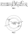
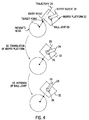
- Figures 2 and 3 illustrates arrangements within a surgical platform according to an embodiment of the present invention.
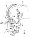
- Figure 4 illustrates separate translational and rotational movements according to an embodiment of the present invention.
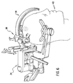
- Figure 5 illustrates an arrangement according to an embodiment of the present invention.
- Figure 6 illustrates and arrangement according to an embodiment of the present invention.
- Figures 7, 8, 9, 10 and 11 illustrate relative arrangements between an attachment arm and a guiding arm according to embodiments of the present invention.
- Figure 12 illustrates an arrangement between a surgical platform and a needle guide according to an embodiment of the present invention.
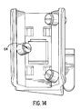
- Figures 13 and 14 illustrate portions of a surgical platform according to an embodiment of the present invention.
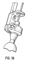
- FIGS 15, 16, 17 and 18 illustrate needle guide arrangements according to embodiments of the present invention.
- a neurosurgeon selects an "entry" point and a "target" point in a preoperative image volume (e.g., CT or MR).
- the target point is the point the neurosurgeon wishes to reach, e.g., to obtain a sample of tissue or implant an electrode.
- the entry point is the point on the skull that the neurosurgeon wishes to go through to reach the target point.
- the entry point and the target point together define a "trajectory," (i.e., the line passing through these two points).
- the general purpose of the surgical device is to direct a surgical needle (such as a biopsy needle or electrode or whatever) such that it passes through the entry point and stops at the target. Biopsy devices are an integral part of most stereotactic frame systems.
- the biopsy device according to the present invention may be used for any frameless image-guided surgical navigation systems.
- the first step in the surgical guide system is getting a surgical platform (biopsy car or biopsy platform) close to the trajectory.
- a surgical platform biopsy car or biopsy platform
- One embodiment uses a guide arm arc and a biopsy car that slides along the guide arm arc.
- the patient's head is rigidly fixed in a head clamp such as a Mayfield® head clamp.
- the head clamp is affixed to an operating table.
- the arc is rigidly attached to the head clamp.
- the arc could instead be attached to the operating table or to something else rigidly attached to the table.
- the arc swivels about its two joints at one end.
- the arc could swivel about its two ends.
- the biopsy platform is connected to the biopsy car that slides along the arc. With these various degrees of freedom, the biopsy platform can be placed over a wide region of the head.
- frame-based surgical devices typically work with a specific geometrical design (e.g., a circular arc with a specific radius).
- the image coordinates of the entry and target points are converted to physical space coordinates, and these are converted to a set of biopsy device parameters (e.g., arc angles and position along the arc).
- the arc serves as a device to get the biopsy platform close to the trajectory, and thus does not need to be as carefully constructed.
- the primary requirement of the arc is that it be mechanically sturdy. In fact the present invention could be implemented without an arc, although it may be the easiest way to manufacture a mechanically solid support.
- Another approach according to an embodiment of the present invention is to have the biopsy platform connected to a multi-jointed arm that is in turn rigidly attached to the head clamp or the operating table.
- the biopsy platform consists of a movable metal plate sandwiched within an annular metal support.
- the metal plate can be locked in place with a set screw, for example.
- a ball joint is located in the center of the metal plate.
- a biopsy sleeve passes through the middle of the ball joint and can accommodate both an intraoperative localization device (ILD) and a biopsy guide.
- the ball joint can be locked in place with a set screw.
- the biopsy platform is connected to the biopsy car with a screw. The biopsy platform can be moved by loosening the screw.
- the position of 3 pivot point and orientation of the biopsy sleeve is set as follows.
- the pivot point is located at the center of the ball joint.
- the present inventors have recognized that it is not necessary to be at the entry point (e.g., of the body) but rather need only be on the trajectory.
- position and orientation may be decoupled. Because it is necessary to be on the trajectory rather than at a specific point on the line, the biopsy sleeve can be positioned with a two-dimensional (2D) translation of the biopsy platform.
- the biopsy platform does not need to be perpendicular to the trajectory.
- the ILD is placed in the biopsy sleeve.
- the ILD is a probe connected to a handle with infrared emitting diodes (IREDs) that are tracked by an optical position sensor (OPS), but which could also be for other frameless systems different types of devices, e.g., an articulated mechanical arm, an electromagnetic device, or an ultrasonic device.
- OPS optical position sensor
- the biopsy platform or metal plate is moved until the ILD position, which is calibrated such that it corresponds to the center of the ball joint (or pivot point), is on the trajectory. When it is on the trajectory, the metal plate is locked in place.
- the proper two-dimensional transitional movement can be accomplished as follows. An image volume consisting of slices perpendicular to the trajectory is created.
- the navigation system converts the physical space position of the ILD to the image coordinate system.
- the position of the ILD relative to the image is displayed on the screen along with the position of the trajectory in the appropriate image slice.
- the plate is moved until the position of the ILD coincides with the position of the trajectory. Additional information can be provided to make the task easier, e.g., a zoomed image and/or the distance of the ILD from the trajectory.
- the ball joint After the ILD position (e.g., the position of the pivot point) is translated such that it is on the trajectory (and thus the center of the ball joint is on the trajectory), the ball joint is rotated until the orientation of the ILD (and thus the orientation of the axis of the biopsy sleeve) coincides with the orientation of the trajectory. When the proper orientation is found, the ball joint is locked in place.
- the proper orientation can be achieved as follows. An image volume consisting of slices perpendicular to the trajectory is created. The navigation system converts the position and orientation of the ILD in physical space to the position and orientation in the image coordinate system.
- This information is used to calculate the intersection of the trajectory of the ILD (and thus the trajectory of the axis of the biopsy sleeve) with the image slice that passes through the target and is perpendicular to the desired entry-target trajectory.
- the position of both this intersection and the target is displayed in this slice.
- the ball joint is rotated until this intersection coincides with the target.
- additional information can be provided to make the task easier, e.g., a zoomed image and/or the distance of the intersection from the target.
- the slice passing through the target is displayed.
- any image slice could be displayed according to other embodiments of the present invention.
- the distance between the ILD position (i.e., the position of the center of the ball joint or pivot point) and the target is calculated by the navigation system software.
- the navigation system software determines the location on the trajectory of the pivot point (i.e., the center of the ball joint).
- a biopsy can be accomplished by placing a biopsy guide into the sleeve and then using traditional biopsy techniques.
- the use of the distance between the pivot point and the target to set a collar or stop on a biopsy needle is straightforward.
- IRED's could be placed on the biopsy needle and tracked by the optical position sensor (OPS).
- OPS optical position sensor
- This implementation is also extendable to other frameless systems. For example, an ultrasonic navigation system could be used to accomplish an image-guided biopsy by placing spark gaps on the biopsy needle.
- the present invention provides a surgical guide including a surgical platform that will remain stable under normal surgical conditions and a guide arm allowing the surgeon to precisely locate the platform using computer guided feedback.
- the system is not directly connected to the patient and is capable of attachment and detachment with no impact on the integrity of the sterile field.
- a surgical guide includes an attachment bar, a guide arm (or arc) and a surgical platform.
- a biopsy needle guide is used to provide stability while tracking the biopsy needle.
- An attachment bar is connected to a starburst joint at a base of a Mayfield®-type skull clamp (or other type head clamp).
- the guide arm (or arc) is connected to one side of the attachment bar.
- the guide arm provides support for the surgical platform.
- the guide arm allows the surgical platform (or biopsy car) to be positioned on a theoretical sphere around the patient's head and can be adjusted in at least two ways.
- the guide arm can be moved closer to or further from the head by sliding it along a shaft extension on the attachment arm.
- the guide arm can also be rotated around a theoretical center of the head in a manner similar to the rotation of the visor of a helmet.
- the guide arm is locked by a knob for sliding and a lever for rotating independently.
- the guide arm sliding and rotating motion can be used to adjust and locate the correct position of the surgical platform relative to a predetermined entry point and target point of a patient.
- the surgical platform (or biopsy car) can slide and lock along the entire length of the guide arm arc to provide an additional gross adjustment.
- the guide arm sliding and rotating adjustment and the platform sliding and locking adjustment along the guide arm arc provide three gross (course) adjustments to provide access to most regions of surgical interest near a patient (for example, regions of interest on a patient's head).
- a surgical platform is a surgical platform where the tools required for the surgical procedure are located.
- a biopsy needle may be provided at the surgical platform.
- a surgeon uses the guide arm arc as a track and, for example, using rollers to slide along the guide arm arc, can be locked in a general position to provide a position for a pivot point ball joint near the entry site of the patient.
- the surgical tools are held in the pivot ball joint which can also be adjusted for a particular desired angular approach to the target site.
- the surgical platform includes two fine adjustment or location parameters. As a first fine adjustment for the guide arm, two sliding surfaces with a locking lever allow the center of the pivot ball joint to be precisely positioned on the previously determined approach vector (or trajectory).
- a second adjustment contained in the pivot ball joint assembly allows the surgical tools to be precisely oriented to the correct approach angle. Fine adjustment of the surgical approach is contained in the pivot ball joint assembly in Phi, theta and the angle relative to the tangent of the theoretical sphere.
- a needle guide is required for a biopsy application according to an embodiment of the present application to maintain the planned trajectory for the entire length of the biopsy needle.
- the needle guide allows the surgeon to define the point of the biopsy needle to be tracked with application software (for example, AcustarTM surgical navigation system software).
- application software for example, AcustarTM surgical navigation system software.
- the end tip of the biopsy needle may be choosen as the working point or the "working" portion of the needle may be tracked. It is important for some position along the biopsy needle guide to be tracked to determine the location thereof.
- a particularly advantageous location of the biopsy needle guide to be tracked is the point at which the surgical tool projects through the pivot ball joint. The ability to define the point to be tracked minimizes errors that can occur.
- a surgeon can then verify the surgical approach trajectory in a visual manner using a localization guidance system and computer processed image software.
- the localization device is attached to the surgical tool in a well defined manner.
- the localization device used in an embodiment of the present invention can be an array of infrared emitting diodes read by a calibrated sensor.
- the present invention provides a sterile surgery field integrity which can be easily maintained when attaching, detaching, and reattaching the guide arm and surgical platform for different procedures during one operating setup. Additionally, the present invention allows easy adjustment of a guidance system to accommodate different head sizes. Further, the present invention allows a stable and accurate positioning of the surgical platform by using a localization guidance system which eliminates the need to affix the platform to the patient's skull.
- the platform position is adjustable in r, theta and phi directions.
- the pivot ball joint can be adjusted in x, y directions and the needle (surgical tool) can be rotated through a 90 degree cone. This allows a full coverage of the skull for most surgical procedures.
- the present invention additionally allows surgeon definition of the biopsy needle (or other tool) position to be tracked. Additionally, in conjunction with an image guided surgical system (for example, AcustarTM navigation software) the defined needle (or other surgical tool) position can be tracked in real time.
- an image guided surgical system for example, AcustarTM navigation software
- the system additionally requires no calculations to be implemented in the operating room theater when used in conjunction with an image guided surgical system.
- FIG 1 illustrates an embodiment of the present invention.
- a biopsy car 10 (or surgical platform) slides back and forth along a guide arm (or arc) 12. Additionally, the arc 12 can rotate at least at one end thereof to cover large portions of the patient's head 14.
- the guide arm arc is attached to an attachment bar (not illustrated in Figure 1) which can be attached to a head clamp such as a Mayfield®-type head clamp attached to the patient's head 14.
- the guide arm arc 12 is rotatable (swivel) at one or both ends thereof so that the guide arm arc 12 passes generally over a particular area of interest of the patient's head 14.
- the surgical platform 10 is slid along the guide arm arc 12 to a particular area of interest of the patient's head 14. The surgical platform 10 is then locked down on the arc 12.
- Figures 2 and 3 illustrate portions of the surgical platform 10 according to an embodiment of the present invention.
- Figure 2 illustrates portions of the surgical platform from a top view
- Figure 3 illustrates sections of the surgical platform from a side view.
- Reference numeral A represents an annular metal support
- reference numeral B represents a movable metal plate
- reference numeral C represents a ball joint (or a pivot point)
- reference numerals D and E represent set screws.
- Set screw D is then used to lock the movable metal plate B relative to the annular metal support A.
- Ball joint C can then be rotated to adjust and access of a surgical device sleeve along a particular trajectory line. Once the ball joint (pivot point C) has been adjusted in this matter, set screw E is used to lock ball joint C in position.
- Figure 4 illustrates a method of adjusting the biopsy platform 22 and a biopsy sleeve 24 which extends through a ball joint 26 within the biopsy platform 22 relative to a trajectory 28.
- Trajectory 28 is a trajectory line in a pre-operative image, for example, which extends through an entry point and a target point of the patient's head.
- the biopsy platform 22 along with the biopsy sleeve 24 and ball joint 26 are translated in a two dimensional manner so that the ball joint 26 extends through any point along the trajectory line 28.
- the point along the trajectory is a point which is outside the patient's head but is somewhere along trajectory line 28.
- the biopsy platform (for example, the metal plate B of Figures 2 and 3) is locked into position. Once the original two dimensional translation of the biopsy platform is performed to extend the center of the ball joint 26 to a point on a trajectory line 28, an additional rotation of the ball joint 26 is made to extend an access of the biopsy sleeve 24 to follow the trajectory line 28.
- the present invention allows a decoupling of different adjustments in order to line the surgical sleeve up with a trajectory line along a target and entry point of a patient.
- the present invention recognizes that a surgeon does not have to line up the swivel point at an entry point on the patient. The surgeon only needs to find the trajectory line and then rotate the surgical sleeve until the sleeve is lined up with a trajectory line on an image in the operating room.
- the surgical sleeve can be provided with light emitting diodes (LEDs) to track the position in the operating room using, for example, the AcustarTM navigational software.
- LEDs light emitting diodes
- the universal ball joint provided within the metal plate is used as a reference point.
- the system navigation software knows the location of the target and the entry point on the patient's head and the reference point position of the ball joint, the distance from the ball joint (or metal plate) to the target can be calculated.
- the surgical instrument can be calibrated so that the surgeon can extend the surgical instrument through the ball joint directly to the target so that the tip of the surgical instrument is directly at the target without going past the target.
- the present invention allows a surgeon to sit down with pre-operative images, for example, and pre-plan a target point, entry point, and a trajectory to be implemented in the surgery.
- the present invention then allows the surgeon to find the target and entry points and the trajectory along the target point and entry point at the time of surgery without performing any measurements from the images or any other sort of calculations.
- the present invention additionally allows parallel trajectories to be used during a surgery. This can be implemented by finding a particular trajectory as defined above. Then the surgical platform (or biopsy car) can be unlocked and slid and locked on at a new point to provide a perfectly parallel trajectory line without any measuring or other sort of calculation.
- the present invention has been described with respect to biopsy, the present invention can be implemented using any sort of other surgical instrument, including the passing of catheters or other functional neurosurgery (for example, guiding endoscope).
- Figure 5 illustrates an embodiment of the present invention including a head clamp 32, an attachment arm 34, a guide arm arc 36 and a surgical platform 38 all arranged around the patient's head 40.
- the head clamp 32 is used to position the patient's head 40 relative to the surgical operation.
- the head clamp 32 may be attached to an operating table.
- Guiding arm 36 can be adjusted relative to attachment 34 in an up and down or curved manner as illustrated by the arrows in Figure 5.
- surgical platform 38 slides along guiding arm arc 36 and holds a surgical instrument or surgical sleeve 44.
- Figure 6 illustrates an arrangement similar to Figure 5 and additionally shows another method of attachment between attachment arm 34 and guiding arm arc 36, and additional possible movement of surgical platform 38.
- Figure 7 illustrated a connection of an attachment arm 34 with a guided arm 36 according to an embodiment of the present invention. Further detail of the portion of Figure 7 within the dotted circle line of Figure 7 is illustrated in Figure 8.
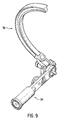
- Figure 9 shows an additional embodiment of the present invention of an attachment between attachment bar 34 and guiding arm 36 from a different angle.
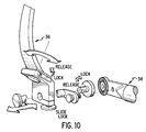
- Figure 10 illustrates a further combination between attachment bar 34 and guiding arm arc 36 according to an embodiment of the present invention.
- Figure 10 illustrates further possible movement between attachment arm 34 and guiding arm 35 for original gross (course) movement of guiding arm 36 relative to the patient's head.
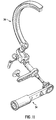
- Figure 11 illustrates further details of a connection between the attachment arm 34 and guiding arm 36 according to an embodiment of the present invention.
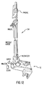
- Figure 12 illustrates an arrangement of a surgical platform 10 relative to a surgical needle guide and probe arrangement 54 according to an embodiment of the present invention.
- Figure 13 illustrates a portion of the surgical platform 10 which slides along the guiding arm 12 according to an embodiment of the present invention.
- Figure 14 illustrates an underside portion of the surgical platform which slides along the guiding arm via rollers 64.
- Figure 15 illustrates a biopsy needle guide arrangement which may be implemented according to an embodiment of the present invention. Further detail of the surgical needle guide arrangement of Figure 15 within the dotted line thereof is illustrated in Figure 16.
- Figure 17 illustrates a needle guide which may be implemented according to an embodiment of the present invention. Further detail of the needle guide of Figure 17 withing the dotted line thereof is illustrated in Figure 18.
- the ILD (iroperative localization device) which tracks the location of the pivot point and the allignment of the surgical sleeve projecting therethrough is used to display an image based on the position of the pivot point and the position of the desired target, entry point and trajectory line.
- the localization software will project these points and lines on various image slices. As the surgeon moves the various surgical platforms, metal plate, ball joint and surgical sleeve, the alignment of the trajectory line relative to the ball joint position and surgical sleeve orientation are displayed on a screen. First, the localization software displays the pivot point relative to the trajectory line and provides an indication pointing out to the surgeon the distance between the closest point on the trajectory line, for example, relative to the pivot point. Once the pivot point is locked on to a position along the trajectory line, the navigational software then projects the relative position of the surgical sleeve axis relative to the trajectory line.
Abstract
Description
Claims (4)
- A surgical guide comprising:a guiding arm;a surgical platform slidable along said guiding arm;a metal plate connected to said surgical platform;a ball joint located in a center of said metal plate; anda surgical sleeve passing through a middle of said ball joint.
- A surgical guide according to Claim 1, wherein said surgical guide comprises a biopsy guide.
- A method of performing a surgical procedure comprising steps of:moving a surgical guide near a desired trajectory line;aligning a pivot point of the surgical guide with a point along the desired trajectory line; andpivoting the pivot point such that a surgical sleeve of the surgical guide is aligned along the trajectory line.
- A method according to Claim 3, wherein said surgical guide is a biopsy guide.
Applications Claiming Priority (2)
| Application Number | Priority Date | Filing Date | Title |
|---|---|---|---|
| US723402 | 1996-09-30 | ||
| US08/723,402 US5984930A (en) | 1996-09-30 | 1996-09-30 | Biopsy guide |
Publications (3)
| Publication Number | Publication Date |
|---|---|
| EP0832611A2 true EP0832611A2 (en) | 1998-04-01 |
| EP0832611A3 EP0832611A3 (en) | 1998-09-30 |
| EP0832611B1 EP0832611B1 (en) | 2005-06-29 |
Family
ID=24906108
Family Applications (1)
| Application Number | Title | Priority Date | Filing Date |
|---|---|---|---|
| EP97307600A Expired - Lifetime EP0832611B1 (en) | 1996-09-30 | 1997-09-26 | Image guided surgery system |
Country Status (4)
| Country | Link |
|---|---|
| US (1) | US5984930A (en) |
| EP (1) | EP0832611B1 (en) |
| JP (1) | JPH10174687A (en) |
| DE (1) | DE69733624T2 (en) |
Cited By (12)
| Publication number | Priority date | Publication date | Assignee | Title |
|---|---|---|---|---|
| WO1998051229A1 (en) * | 1997-05-15 | 1998-11-19 | Regents Of The University Of Minnesota | Trajectory guides for surgical instruments |
| US5904691A (en) * | 1996-09-30 | 1999-05-18 | Picker International, Inc. | Trackable guide block |
| WO2000019927A1 (en) * | 1998-10-08 | 2000-04-13 | Regents Of The University Of Minnesota | Method and apparatus for positioning a device in a body |
| US6079681A (en) * | 1997-09-26 | 2000-06-27 | Picker International, Inc. | MR compatible neurosurgical positioning apparatus |
| WO2000015132A3 (en) * | 1998-09-11 | 2000-07-27 | Brian Hynes | Apparatus for frameless stereotactic surgery |
| WO2002013714A1 (en) * | 2000-08-17 | 2002-02-21 | Image Guided Neurologies, Inc. | Trajectory guide with instrument immobilizer |
| WO2001076498A3 (en) * | 2000-04-07 | 2002-04-18 | Image Guided Neurologics Inc | Deep organ access device and method |
| US6921406B1 (en) | 2001-04-19 | 2005-07-26 | The Ohio State University | Stereotactic apparatus and methods |
| DE19826386B4 (en) * | 1998-06-12 | 2007-08-30 | Mht Medical High Tech Gmbh | Navigation system for surgical purposes and use of such |
| US9901713B2 (en) | 2002-09-17 | 2018-02-27 | Medtronic, Inc. | Low profile instrument immobilizer |
| US10086193B2 (en) | 2004-02-13 | 2018-10-02 | Medtronic, Inc. | Apparatus for securing a therapy delivery device within a burr hole and method for making same |
| CN109480836A (en) * | 2019-01-11 | 2019-03-19 | 苏州大学附属儿童医院 | A kind of eeg monitoring wearable device |
Families Citing this family (88)
| Publication number | Priority date | Publication date | Assignee | Title |
|---|---|---|---|---|
| US5695501A (en) * | 1994-09-30 | 1997-12-09 | Ohio Medical Instrument Company, Inc. | Apparatus for neurosurgical stereotactic procedures |
| US6752812B1 (en) | 1997-05-15 | 2004-06-22 | Regent Of The University Of Minnesota | Remote actuation of trajectory guide |
| US6529765B1 (en) | 1998-04-21 | 2003-03-04 | Neutar L.L.C. | Instrumented and actuated guidance fixture for sterotactic surgery |
| US6298262B1 (en) | 1998-04-21 | 2001-10-02 | Neutar, Llc | Instrument guidance for stereotactic surgery |
| US6546277B1 (en) | 1998-04-21 | 2003-04-08 | Neutar L.L.C. | Instrument guidance system for spinal and other surgery |
| US6110182A (en) * | 1998-06-22 | 2000-08-29 | Ohio Medical Instruments Company, Inc. | Target socket |
| US6282437B1 (en) | 1998-08-12 | 2001-08-28 | Neutar, Llc | Body-mounted sensing system for stereotactic surgery |
| US6351662B1 (en) | 1998-08-12 | 2002-02-26 | Neutar L.L.C. | Movable arm locator for stereotactic surgery |
| US6491699B1 (en) * | 1999-04-20 | 2002-12-10 | Surgical Navigation Technologies, Inc. | Instrument guidance method and system for image guided surgery |
| US6132437A (en) * | 1999-07-14 | 2000-10-17 | Omurtag; Ahmet | Method and stereotactic apparatus for locating intracranial targets guiding surgical instruments |
| WO2001064124A1 (en) | 2000-03-01 | 2001-09-07 | Surgical Navigation Technologies, Inc. | Multiple cannula image guided tool for image guided procedures |
| DE10015513A1 (en) * | 2000-03-30 | 2001-10-04 | Siemens Ag | Medical equipment has adjuster for needle enabling needle to pivot around defined rotation point,with adjuster having link arm in form of parallel drive |
| JP2001276080A (en) * | 2000-03-31 | 2001-10-09 | Rikuto:Kk | Acupuncture needle guide for acupuncture device |
| US6306146B1 (en) | 2000-04-06 | 2001-10-23 | Ohio Medical Instrument Company, Inc. | Surgical instrument support and method |
| US7366561B2 (en) | 2000-04-07 | 2008-04-29 | Medtronic, Inc. | Robotic trajectory guide |
| CA2412879A1 (en) * | 2000-06-22 | 2001-12-27 | Nuvasive, Inc. | Polar coordinate surgical guideframe |
| DE10042035A1 (en) * | 2000-08-26 | 2002-03-14 | Daum Gmbh I Ins | Bone marrow examination appliance comprises operating duct, swivel adjustment unit with external arm, and biopsy needle |
| US20020156361A1 (en) * | 2000-10-19 | 2002-10-24 | Youri Popowski | Positioning template for implanting a substance into a patient |
| US6517546B2 (en) | 2001-03-13 | 2003-02-11 | Gregory R. Whittaker | Method and apparatus for fixing a graft in a bone tunnel |
| US7195642B2 (en) | 2001-03-13 | 2007-03-27 | Mckernan Daniel J | Method and apparatus for fixing a graft in a bone tunnel |
| US7594917B2 (en) * | 2001-03-13 | 2009-09-29 | Ethicon, Inc. | Method and apparatus for fixing a graft in a bone tunnel |
| US6695786B2 (en) | 2001-03-16 | 2004-02-24 | U-Systems, Inc. | Guide and position monitor for invasive medical instrument |
| US6770080B2 (en) * | 2001-04-26 | 2004-08-03 | Fenestra Medical, Inc. | Mechanically registered videoscopic myringotomy/tympanostomy tube placement system |
| US7831292B2 (en) * | 2002-03-06 | 2010-11-09 | Mako Surgical Corp. | Guidance system and method for surgical procedures with improved feedback |
| WO2003077101A2 (en) * | 2002-03-06 | 2003-09-18 | Z-Kat, Inc. | System and method for using a haptic device in combination with a computer-assisted surgery system |
| US11202676B2 (en) | 2002-03-06 | 2021-12-21 | Mako Surgical Corp. | Neural monitor-based dynamic haptics |
| US8996169B2 (en) | 2011-12-29 | 2015-03-31 | Mako Surgical Corp. | Neural monitor-based dynamic haptics |
| US8010180B2 (en) | 2002-03-06 | 2011-08-30 | Mako Surgical Corp. | Haptic guidance system and method |
| US7720522B2 (en) | 2003-02-25 | 2010-05-18 | Medtronic, Inc. | Fiducial marker devices, tools, and methods |
| US7787934B2 (en) | 2002-07-29 | 2010-08-31 | Medtronic, Inc. | Fiducial marker devices, tools, and methods |
| US20040243146A1 (en) * | 2002-11-18 | 2004-12-02 | Chesbrough Richard M | Method and apparatus for supporting a medical device |
| US7636596B2 (en) | 2002-12-20 | 2009-12-22 | Medtronic, Inc. | Organ access device and method |
| US7896889B2 (en) | 2003-02-20 | 2011-03-01 | Medtronic, Inc. | Trajectory guide with angled or patterned lumens or height adjustment |
| US20040199154A1 (en) * | 2003-04-02 | 2004-10-07 | Cryocath Technologies Inc. | Device for tissue ablation |
| US7662157B2 (en) * | 2003-08-21 | 2010-02-16 | Osteomed L.P. | Bone anchor system |
| US7641660B2 (en) | 2004-03-08 | 2010-01-05 | Biomet Manufacturing Corporation | Method, apparatus, and system for image guided bone cutting |
| US7497863B2 (en) | 2004-12-04 | 2009-03-03 | Medtronic, Inc. | Instrument guiding stage apparatus and method for using same |
| US7744606B2 (en) | 2004-12-04 | 2010-06-29 | Medtronic, Inc. | Multi-lumen instrument guide |
| EP1846181A2 (en) * | 2005-01-28 | 2007-10-24 | Massachusetts General Hospital | Guidance and insertion system |
| EP1998678B1 (en) * | 2006-03-24 | 2017-09-27 | B-K Medical ApS | Biopsy system |
| US7507210B2 (en) | 2006-05-01 | 2009-03-24 | Ethicon Endo-Surgery, Inc. | Biopsy cannula adjustable depth stop |
| WO2007136769A2 (en) | 2006-05-19 | 2007-11-29 | Mako Surgical Corp. | Method and apparatus for controlling a haptic device |
| US20080163118A1 (en) * | 2006-12-29 | 2008-07-03 | Jason Wolf | Representation of file relationships |
| US8814874B2 (en) | 2007-02-13 | 2014-08-26 | Medtronic Navigation, Inc. | Navigated cut guide for total knee reconstruction |
| US9387124B2 (en) | 2007-04-19 | 2016-07-12 | Tusker Medical, Inc. | Disposable iontophoresis system and tympanic membrane pain inhibition method |
| WO2009014721A2 (en) * | 2007-07-24 | 2009-01-29 | Wake Forest University Health Sciences | Surgical head support system |
| AU2008316640B2 (en) * | 2007-10-26 | 2014-03-06 | Boston Scientific Neuromodulation Corporation | Burr hole plug designs |
| US20090285356A1 (en) * | 2008-05-16 | 2009-11-19 | Sirona Dental Systems Gmbh | System and method for patient positioning in cone-beam tomography |
| DE102009018282A1 (en) * | 2009-04-21 | 2010-12-09 | Siemens Aktiengesellschaft | Location of coils in a magnetic resonance tomography system |
| US9770366B2 (en) | 2009-07-15 | 2017-09-26 | Tusker Medical, Inc. | Tympanic membrane pressure equalization tube delivery system |
| US9539146B2 (en) | 2009-07-15 | 2017-01-10 | Tusker Medical, Inc. | Trigger assembly for tympanostomy tube delivery device |
| US8376938B2 (en) * | 2009-11-20 | 2013-02-19 | Ethicon Endo-Surgery, Inc. | Discrete flexion head for single port device |
| US8282546B2 (en) * | 2009-12-11 | 2012-10-09 | Ethicon Endo-Surgery, Inc. | Inverted conical expandable retractor with coil spring |
| US8231570B2 (en) * | 2009-12-11 | 2012-07-31 | Ethicon Endo-Surgery, Inc. | Inverted conical expandable retractor |
| US8435174B2 (en) * | 2009-12-11 | 2013-05-07 | Ethicon Endo-Surgery, Inc. | Methods and devices for accessing a body cavity |
| US8444557B2 (en) * | 2009-12-11 | 2013-05-21 | Ethicon Endo-Surgery, Inc. | Methods and devices for providing access through tissue to a surgical site |
| US8353873B2 (en) * | 2009-12-11 | 2013-01-15 | Ethicon Endo-Surgery, Inc. | Methods and devices for providing access through tissue to a surgical site |
| US8517932B2 (en) * | 2009-12-11 | 2013-08-27 | Ethicon Endo-Surgery, Inc. | Methods and devices for providing access through tissue to a surgical site |
| US8414483B2 (en) * | 2009-12-11 | 2013-04-09 | Ethicon Endo-Surgery, Inc. | Methods and devices for providing access into a body cavity |
| US8357088B2 (en) * | 2009-12-11 | 2013-01-22 | Ethicon Endo-Surgery, Inc. | Methods and devices for providing access into a body cavity |
| US8500633B2 (en) * | 2009-12-11 | 2013-08-06 | Ethicon Endo-Surgery, Inc. | Methods and devices for providing surgical access through tissue to a surgical site |
| US8460186B2 (en) * | 2009-12-11 | 2013-06-11 | Ethicon Endo-Surgery, Inc. | Methods and devices for providing access through tissue to a surgical site |
| DE102010031737A1 (en) * | 2010-07-21 | 2012-01-26 | Siemens Aktiengesellschaft | Device for tissue removal |
| WO2012027549A1 (en) * | 2010-08-26 | 2012-03-01 | Equipois, Inc. | Multi-arm gimbal system |
| US8603078B2 (en) | 2010-10-13 | 2013-12-10 | Ethicon Endo-Surgery, Inc. | Methods and devices for guiding and supporting surgical instruments |
| US8617176B2 (en) | 2011-08-24 | 2013-12-31 | Depuy Mitek, Llc | Cross pinning guide devices and methods |
| US9498297B2 (en) * | 2012-04-18 | 2016-11-22 | United Arab Emirates University | Manipulator for surgical tools |
| US10292887B2 (en) | 2012-12-31 | 2019-05-21 | Mako Surgical Corp. | Motorized joint positioner |
| US9320652B2 (en) | 2013-03-14 | 2016-04-26 | Tusker Medical, Inc. | Features to improve and sense tympanic membrane apposition by tympanostomy tube delivery instrument |
| US9681891B2 (en) | 2013-03-14 | 2017-06-20 | Tusker Medical, Inc. | Tympanostomy tube delivery device with cutting dilator |
| US10595744B2 (en) * | 2014-02-14 | 2020-03-24 | MRI Interventions, Inc. | Surgical tool-positioning devices and related methods |
| US20160038341A1 (en) | 2014-08-08 | 2016-02-11 | Acclarent, Inc. | Tympanostomy tube delivery device with elastomeric brake |
| US10195086B2 (en) | 2014-08-11 | 2019-02-05 | Tusker Medical, Inc. | Tympanostomy tube delivery device with rotatable |
| US9833359B2 (en) | 2014-08-12 | 2017-12-05 | Tusker Medical, Inc. | Tympanostomy tube delivery device with cutter force clutch |
| US9833360B2 (en) | 2014-08-12 | 2017-12-05 | Tusker Medical, Inc. | Tympanostomy tube delivery device with replaceable shaft portion |
| US10639066B2 (en) | 2014-10-14 | 2020-05-05 | Us Patent Innovations, Llc | System for controlling displacement of an intervention device |
| JP6382450B2 (en) * | 2014-12-12 | 2018-08-29 | エレクタ アクチボラゲット(パブル) | Stereotaxic instruments |
| US10682156B2 (en) | 2015-05-28 | 2020-06-16 | Akm A. Rahman | Angle-guidance device and method for CT guided drainage and biopsy procedures |
| US10232169B2 (en) | 2015-07-23 | 2019-03-19 | Boston Scientific Neuromodulation Corporation | Burr hole plugs for electrical stimulation systems and methods of making and using |
| US10702257B2 (en) * | 2015-09-29 | 2020-07-07 | Ethicon Llc | Positioning device for use with surgical instruments |
| CN106175893B (en) * | 2016-08-03 | 2018-10-30 | 福建医科大学附属第一医院 | A kind of device of arching trajectory implantation intracranial electrode |
| US9707049B1 (en) | 2016-12-22 | 2017-07-18 | The Florida International University Board Of Trustees | Stereotactic device for implantation of permanent implants into a rodent brain |
| JP2021502215A (en) | 2017-11-13 | 2021-01-28 | ボストン サイエンティフィック ニューロモデュレイション コーポレイション | Systems and methods for manufacturing and using flat control modules for electrical stimulation systems |
| WO2019143574A1 (en) | 2018-01-16 | 2019-07-25 | Boston Scientific Neuromodulation Corporation | An electrical stimulation system with a case-neutral battery and a control module for such a system |
| US11058870B2 (en) | 2018-03-09 | 2021-07-13 | Boston Scientific Neuromodulation Corporation | Burr hole plugs for electrical stimulation systems and methods of making and using |
| US11013913B2 (en) | 2018-03-16 | 2021-05-25 | Boston Scientific Neuromodulation Corporation | Kits and methods for securing a burr hole plugs for stimulation systems |
| US10251722B1 (en) | 2018-09-17 | 2019-04-09 | The Florida International University Board Of Trustees | Stereotaxic brain implant system for large animals |
| US11925511B2 (en) | 2020-01-31 | 2024-03-12 | Clearpoint Neuro, Inc. | Surgical tool support systems including elongate support legs with adjustable lengths and related methods |
Citations (9)
| Publication number | Priority date | Publication date | Assignee | Title |
|---|---|---|---|---|
| US2580427A (en) | 1944-08-11 | 1952-01-01 | Heiland Res Corp | Recording system |
| US4386602A (en) | 1977-05-17 | 1983-06-07 | Sheldon Charles H | Intracranial surgical operative apparatus |
| US4465069A (en) | 1981-06-04 | 1984-08-14 | Barbier Jean Y | Cranial insertion of surgical needle utilizing computer-assisted tomography |
| US4592352A (en) | 1984-11-30 | 1986-06-03 | Patil Arun A | Computer-assisted tomography stereotactic system |
| US4602622A (en) | 1979-12-05 | 1986-07-29 | Siemens Aktiengesellschaft | Medical examination installation |
| US4617925A (en) | 1984-10-01 | 1986-10-21 | Laitinen Lauri V | Adapter for definition of the position of brain structures |
| US4638789A (en) | 1985-01-16 | 1987-01-27 | Rinnai Kabushiki Kaisha | Safety apparatus for combustion device |
| US5257998A (en) | 1989-09-20 | 1993-11-02 | Mitaka Kohki Co., Ltd. | Medical three-dimensional locating apparatus |
| US5387220A (en) | 1993-06-15 | 1995-02-07 | Pisharodi; Maohaven | Stereotactic frame and localization method |
Family Cites Families (9)
| Publication number | Priority date | Publication date | Assignee | Title |
|---|---|---|---|---|
| US2697433A (en) * | 1951-12-04 | 1954-12-21 | Max A Zehnder | Device for accurately positioning and guiding guide wires used in the nailing of thefemoral neck |
| US3115140A (en) * | 1960-08-18 | 1963-12-24 | Baltimore Instr Company | Apparatus for stereotaxic brain operations |
| US3457922A (en) * | 1966-12-13 | 1969-07-29 | Charles D Ray | Stereotaxic surgical instrument and method |
| US4638798A (en) * | 1980-09-10 | 1987-01-27 | Shelden C Hunter | Stereotactic method and apparatus for locating and treating or removing lesions |
| US5030223A (en) * | 1989-06-30 | 1991-07-09 | Iowa State University Research Foundation, Inc. | Head mounted stereotaxic apparatus |
| EP0465609A4 (en) * | 1989-11-27 | 1992-08-26 | Bard International, Inc. | Puncture guide for computer tomography |
| US5320628A (en) * | 1993-06-28 | 1994-06-14 | Kevin Ufkin | Multiple movement single control positioning device |
| US5776143A (en) * | 1994-02-18 | 1998-07-07 | Implico B.V. | Stereostatic pointing device |
| US5695501A (en) * | 1994-09-30 | 1997-12-09 | Ohio Medical Instrument Company, Inc. | Apparatus for neurosurgical stereotactic procedures |
-
1996
- 1996-09-30 US US08/723,402 patent/US5984930A/en not_active Expired - Fee Related
-
1997
- 1997-09-26 DE DE69733624T patent/DE69733624T2/en not_active Expired - Fee Related
- 1997-09-26 EP EP97307600A patent/EP0832611B1/en not_active Expired - Lifetime
- 1997-09-30 JP JP9267299A patent/JPH10174687A/en active Pending
Patent Citations (9)
| Publication number | Priority date | Publication date | Assignee | Title |
|---|---|---|---|---|
| US2580427A (en) | 1944-08-11 | 1952-01-01 | Heiland Res Corp | Recording system |
| US4386602A (en) | 1977-05-17 | 1983-06-07 | Sheldon Charles H | Intracranial surgical operative apparatus |
| US4602622A (en) | 1979-12-05 | 1986-07-29 | Siemens Aktiengesellschaft | Medical examination installation |
| US4465069A (en) | 1981-06-04 | 1984-08-14 | Barbier Jean Y | Cranial insertion of surgical needle utilizing computer-assisted tomography |
| US4617925A (en) | 1984-10-01 | 1986-10-21 | Laitinen Lauri V | Adapter for definition of the position of brain structures |
| US4592352A (en) | 1984-11-30 | 1986-06-03 | Patil Arun A | Computer-assisted tomography stereotactic system |
| US4638789A (en) | 1985-01-16 | 1987-01-27 | Rinnai Kabushiki Kaisha | Safety apparatus for combustion device |
| US5257998A (en) | 1989-09-20 | 1993-11-02 | Mitaka Kohki Co., Ltd. | Medical three-dimensional locating apparatus |
| US5387220A (en) | 1993-06-15 | 1995-02-07 | Pisharodi; Maohaven | Stereotactic frame and localization method |
Cited By (24)
| Publication number | Priority date | Publication date | Assignee | Title |
|---|---|---|---|---|
| US5904691A (en) * | 1996-09-30 | 1999-05-18 | Picker International, Inc. | Trackable guide block |
| US6206890B1 (en) | 1997-05-15 | 2001-03-27 | Regents Of The University Of Minnesota | Remote actuation of trajectory guide |
| US5993463A (en) * | 1997-05-15 | 1999-11-30 | Regents Of The University Of Minnesota | Remote actuation of trajectory guide |
| WO1998051229A1 (en) * | 1997-05-15 | 1998-11-19 | Regents Of The University Of Minnesota | Trajectory guides for surgical instruments |
| US6368329B1 (en) | 1997-05-15 | 2002-04-09 | Regents Of The University Of Minnesota | Method of using trajectory guide |
| US6267770B1 (en) | 1997-05-15 | 2001-07-31 | Regents Of The University Of Minnesota | Remote actuation of trajectory guide |
| US6079681A (en) * | 1997-09-26 | 2000-06-27 | Picker International, Inc. | MR compatible neurosurgical positioning apparatus |
| DE19826386B4 (en) * | 1998-06-12 | 2007-08-30 | Mht Medical High Tech Gmbh | Navigation system for surgical purposes and use of such |
| DE19826386B9 (en) * | 1998-06-12 | 2007-12-06 | Mht Medical High Tech Gmbh | Navigation system for surgical purposes and use of such |
| WO2000015132A3 (en) * | 1998-09-11 | 2000-07-27 | Brian Hynes | Apparatus for frameless stereotactic surgery |
| US6368330B1 (en) | 1998-09-11 | 2002-04-09 | Hybex Surgical Specialties Inc. | Apparatus for frameless stereotactic surgery |
| WO2000019927A1 (en) * | 1998-10-08 | 2000-04-13 | Regents Of The University Of Minnesota | Method and apparatus for positioning a device in a body |
| US10300268B2 (en) | 2000-04-07 | 2019-05-28 | Medtronic, Inc. | Device for immobilizing a primary instrument and method therefor |
| WO2001076498A3 (en) * | 2000-04-07 | 2002-04-18 | Image Guided Neurologics Inc | Deep organ access device and method |
| US7660621B2 (en) | 2000-04-07 | 2010-02-09 | Medtronic, Inc. | Medical device introducer |
| WO2002013714A1 (en) * | 2000-08-17 | 2002-02-21 | Image Guided Neurologies, Inc. | Trajectory guide with instrument immobilizer |
| US6921406B1 (en) | 2001-04-19 | 2005-07-26 | The Ohio State University | Stereotactic apparatus and methods |
| US10058681B2 (en) | 2002-09-17 | 2018-08-28 | Medtronic, Inc. | Low profile instrument immobilizer |
| US9901713B2 (en) | 2002-09-17 | 2018-02-27 | Medtronic, Inc. | Low profile instrument immobilizer |
| US10974029B2 (en) | 2002-09-17 | 2021-04-13 | Medtronic, Inc. | Low profile instrument immobilizer |
| US10086193B2 (en) | 2004-02-13 | 2018-10-02 | Medtronic, Inc. | Apparatus for securing a therapy delivery device within a burr hole and method for making same |
| US11938312B2 (en) | 2004-02-13 | 2024-03-26 | Medtronic, Inc. | Apparatus for securing a therapy delivery device within a burr hole and method for making same |
| CN109480836A (en) * | 2019-01-11 | 2019-03-19 | 苏州大学附属儿童医院 | A kind of eeg monitoring wearable device |
| CN109480836B (en) * | 2019-01-11 | 2021-10-26 | 苏州大学附属儿童医院 | Wearing equipment for electroencephalogram monitoring |
Also Published As
| Publication number | Publication date |
|---|---|
| US5984930A (en) | 1999-11-16 |
| EP0832611B1 (en) | 2005-06-29 |
| EP0832611A3 (en) | 1998-09-30 |
| DE69733624T2 (en) | 2006-05-18 |
| DE69733624D1 (en) | 2005-08-04 |
| JPH10174687A (en) | 1998-06-30 |
Similar Documents
| Publication | Publication Date | Title |
|---|---|---|
| US5984930A (en) | Biopsy guide | |
| EP0783279B1 (en) | Apparatus for neurosurgical stereotactic procedures | |
| EP0895461B1 (en) | Apparatus for surgical stereotactic procedures | |
| US6529765B1 (en) | Instrumented and actuated guidance fixture for sterotactic surgery | |
| US6351662B1 (en) | Movable arm locator for stereotactic surgery | |
| US6282437B1 (en) | Body-mounted sensing system for stereotactic surgery | |
| AU2017323599B2 (en) | Systems and methods for surgical navigation, including image-guided navigation of a patient's head | |
| US5665095A (en) | Stereotactic guidance device | |
| US6546277B1 (en) | Instrument guidance system for spinal and other surgery | |
| EP3216416B1 (en) | Reference device for surgical navigation system | |
| US7776056B2 (en) | Instrument guide system | |
| US5221283A (en) | Apparatus and method for stereotactic surgery | |
| US20080004523A1 (en) | Surgical tool guide | |
| US20070191867A1 (en) | Trajectory guide with angled or patterned guide lumens or height adjustment | |
| US20050215888A1 (en) | Universal support arm and tracking array | |
| US20130066334A1 (en) | Axial Surgical Trajectory Guide | |
| EP2567668A1 (en) | Axial surgical trajectory guide for guiding a medical device | |
| US20130066232A1 (en) | Axial Surgical Trajectory Guide | |
| JP2004202242A (en) | Instrument for surgical operation and positioning method for it | |
| US11744598B2 (en) | System for neuronavigation registration and robotic trajectory guidance, robotic surgery, and related methods and devices | |
| JP7058690B2 (en) | Systems for registering neuronavigation and guiding robot trajectories, robotic surgery, and related methods and equipment | |
| EP3847989A1 (en) | System for neuronavigation registration and robotic trajectory guidance, robotic surgery, and related methods and devices | |
| JP7323489B2 (en) | Systems and associated methods and apparatus for robotic guidance of a guided biopsy needle trajectory | |
| US20230404686A1 (en) | Coupler For Robotic End Effector | |
| US20200297451A1 (en) | System for robotic trajectory guidance for navigated biopsy needle, and related methods and devices |
Legal Events
| Date | Code | Title | Description |
|---|---|---|---|
| PUAI | Public reference made under article 153(3) epc to a published international application that has entered the european phase |
Free format text: ORIGINAL CODE: 0009012 |
|
| AK | Designated contracting states |
Kind code of ref document: A2 Designated state(s): DE FR GB |
|
| PUAL | Search report despatched |
Free format text: ORIGINAL CODE: 0009013 |
|
| AK | Designated contracting states |
Kind code of ref document: A3 Designated state(s): AT BE CH DE DK ES FI FR GB GR IE IT LI LU MC NL PT SE |
|
| 17P | Request for examination filed |
Effective date: 19990326 |
|
| AKX | Designation fees paid |
Free format text: DE FR GB |
|
| 17Q | First examination report despatched |
Effective date: 20021022 |
|
| GRAP | Despatch of communication of intention to grant a patent |
Free format text: ORIGINAL CODE: EPIDOSNIGR1 |
|
| RTI1 | Title (correction) |
Free format text: IMAGE GUIDED SURGERY SYSTEM |
|
| GRAS | Grant fee paid |
Free format text: ORIGINAL CODE: EPIDOSNIGR3 |
|
| GRAA | (expected) grant |
Free format text: ORIGINAL CODE: 0009210 |
|
| AK | Designated contracting states |
Kind code of ref document: B1 Designated state(s): DE FR GB |
|
| REG | Reference to a national code |
Ref country code: GB Ref legal event code: FG4D |
|
| REF | Corresponds to: |
Ref document number: 69733624 Country of ref document: DE Date of ref document: 20050804 Kind code of ref document: P |
|
| PGFP | Annual fee paid to national office [announced via postgrant information from national office to epo] |
Ref country code: FR Payment date: 20050919 Year of fee payment: 9 |
|
| PGFP | Annual fee paid to national office [announced via postgrant information from national office to epo] |
Ref country code: GB Payment date: 20050921 Year of fee payment: 9 |
|
| PGFP | Annual fee paid to national office [announced via postgrant information from national office to epo] |
Ref country code: DE Payment date: 20051031 Year of fee payment: 9 |
|
| ET | Fr: translation filed | ||
| PLBE | No opposition filed within time limit |
Free format text: ORIGINAL CODE: 0009261 |
|
| STAA | Information on the status of an ep patent application or granted ep patent |
Free format text: STATUS: NO OPPOSITION FILED WITHIN TIME LIMIT |
|
| 26N | No opposition filed |
Effective date: 20060330 |
|
| PG25 | Lapsed in a contracting state [announced via postgrant information from national office to epo] |
Ref country code: DE Free format text: LAPSE BECAUSE OF NON-PAYMENT OF DUE FEES Effective date: 20070403 |
|
| GBPC | Gb: european patent ceased through non-payment of renewal fee |
Effective date: 20060926 |
|
| REG | Reference to a national code |
Ref country code: FR Ref legal event code: ST Effective date: 20070531 |
|
| PG25 | Lapsed in a contracting state [announced via postgrant information from national office to epo] |
Ref country code: GB Free format text: LAPSE BECAUSE OF NON-PAYMENT OF DUE FEES Effective date: 20060926 |
|
| PG25 | Lapsed in a contracting state [announced via postgrant information from national office to epo] |
Ref country code: FR Free format text: LAPSE BECAUSE OF NON-PAYMENT OF DUE FEES Effective date: 20061002 |