EP0832767A2 - Method of and device for detecting tire pressure drop - Google Patents
Method of and device for detecting tire pressure drop Download PDFInfo
- Publication number
- EP0832767A2 EP0832767A2 EP97116668A EP97116668A EP0832767A2 EP 0832767 A2 EP0832767 A2 EP 0832767A2 EP 97116668 A EP97116668 A EP 97116668A EP 97116668 A EP97116668 A EP 97116668A EP 0832767 A2 EP0832767 A2 EP 0832767A2
- Authority
- EP
- European Patent Office
- Prior art keywords
- vehicle
- speed
- value
- judging
- judged
- Prior art date
- Legal status (The legal status is an assumption and is not a legal conclusion. Google has not performed a legal analysis and makes no representation as to the accuracy of the status listed.)
- Granted
Links
Images


Classifications
-
- B—PERFORMING OPERATIONS; TRANSPORTING
- B60—VEHICLES IN GENERAL
- B60C—VEHICLE TYRES; TYRE INFLATION; TYRE CHANGING; CONNECTING VALVES TO INFLATABLE ELASTIC BODIES IN GENERAL; DEVICES OR ARRANGEMENTS RELATED TO TYRES
- B60C23/00—Devices for measuring, signalling, controlling, or distributing tyre pressure or temperature, specially adapted for mounting on vehicles; Arrangement of tyre inflating devices on vehicles, e.g. of pumps or of tanks; Tyre cooling arrangements
- B60C23/06—Signalling devices actuated by deformation of the tyre, e.g. tyre mounted deformation sensors or indirect determination of tyre deformation based on wheel speed, wheel-centre to ground distance or inclination of wheel axle
- B60C23/061—Signalling devices actuated by deformation of the tyre, e.g. tyre mounted deformation sensors or indirect determination of tyre deformation based on wheel speed, wheel-centre to ground distance or inclination of wheel axle by monitoring wheel speed
Definitions
- the present invention relates to a tire pressure drop detecting method and device for detecting whether the tire pressure drops or not based on the rotational angular velocities of four tires provided for a four-wheel vehicle.
- DWS tire pressure drop
- the effective radius is a value obtained by dividing by 2 ⁇ a travel distance of the vehicle while the tires make one free revolution.
- the slip rate of the tire W i whose pneumatic pressure has dropped is lowered, while the effective rolling radius is increased by a centrifugal force applied to the respective parts of the tire W i . Therefore, the difference in rotational angular velocity between a tire W i having a normal inner pressure and a tire W i whose pneumatic pressure has dropped nearly disappears.
- the judged value D approaches zero in the form of the second order function as the speed V of the vehicle increases even if the pneumatic pressure of any tire W i has dropped, and hardly satisfy the condition of the above expression (2).
- Japanese Patent Application No. 8-92311 (not published as of the day of filing the present application) is a technique of discriminating whether a vehicle is in a state of high-speed drive traveling or not after performing a pneumatic pressure drop judgment using the above expressions (1) and (2) (hereinafter referred to as a "low-speed adapted judgment") regardless of the speed V of the vehicle, and further performing a high-speed adapted judgment when it is found that the vehicle is in a state of high-speed drive traveling as a result of the above judgment.
- a low-speed adapted judgment a technique of discriminating whether a vehicle is in a state of high-speed drive traveling or not after performing a pneumatic pressure drop judgment using the above expressions (1) and (2) (hereinafter referred to as a "low-speed adapted judgment") regardless of the speed V of the vehicle, and further performing a high-speed adapted judgment when it is found that the vehicle is in a state of high-speed drive traveling as a result of the above judgment.
- the speed V of the vehicle when the judged value D is calculated, belongs to which one of a plurality of previously set speed ranges, and the judged value D is classified into the speed range thus determined.
- the average value of the judged values D in each speed range is calculated.
- these average values are plotted in a graph as shown in Fig. 6 and are subjected to a regression processing by applying the least squares method to the respective plots. Consequently, a judged value CrosP when the speed V of the vehicle is 0 is assumed. Then, it is judged whether this assumed judged value CrosP satisfies the judging expression such as the above expression (2) or not.
- the judged value CrosP satisfies the judging expression, it is judged that a tire W i whose pneumatic pressure has dropped is present. If the judged value CrosP does not satisfy the judging expression, it is judged that all tires W i have a normal inner pressure. Consequently, it can be detected that a tire W i whose pneumatic pressure has dropped is present even if the vehicle is in a state of high-speed drive traveling with a tire W i whose pneumatic pressure has dropped.
- the judged value CrosP can not be assumed if the average values of the judged values D can not be calculated in a plurality of speed ranges.
- a high-speed adapted judgment can not be performed if the speed V of the vehicle does not substantially vary.
- the high-speed adapted judgment can not be performed by the above suggested technique at the time of autocruise traveling where the speed V of the vehicle is substantially constant. That is, at the time of autocruise traveling, only a low-speed adapted judgment is performed based on the judged value D which is influenced by the speed V of the vehicle. Accordingly, when the vehicle is in a state of autocruise traveling with high speed, there is a fear of causing an erroneous judgment of the pneumatic pressure drop.
- the pneumatic pressure drop judgment adapted to the high-speed traveling is not performed when the vehicle is in a state of autocruise traveling (traveling under cruise control) with high speed; therefore, there is a fear of causing an erroneous judgment of the pneumatic pressure drop.
- An object of the present invention is to provide a tire pressure drop detecting method, capable of certainly detecting whether the tire pressure has dropped or not even if the vehicle is in a state of autocruise traveling with high speed.
- Another object of the present invention is to provide a tire pressure drop detecting device for carrying out such a method.
- a pneumatic pressure drop judging processing for autocruise traveling is executed. Consequently, it is possible to accurately detect whether the tire pressure has dropped or not even if the vehicle is in a state of autocruise traveling with high speed.
- the tire pressure drop detecting device can be realized at a low price.
- a judged value for pneumatic pressure drop judgment is calculated based on the rotational angular velocities of the tires provided for the vehicle. By comparing this judged value with a judging threshold value, it is judged whether the tire pressure has dropped or not.
- the judging threshold value is set to become smaller as the speed of the vehicle becomes higher.
- a slip rate of the tire whose pneumatic pressure has dropped is lowered, while the effective rolling radius is increased by a centrifugal force applied to the respective parts of the tire. Therefore, the rotational angular velocity of a tire becomes smaller than that at the time of low-speed traveling. Even in such a case, the tire pressure drop can be accurately detected by changing the judging threshold value according to the speed of the vehicle.
- an absolute value of a lateral acceleration of the vehicle is less than an acceleration threshold value
- the judged value and the speed of the vehicle in this case are held or stored.
- the judged value and the speed of the vehicle hardly containing an error are held. That is, when the vehicle is traveling at a corner, there is a fear of causing a transfer of the load of the vehicle or a lateral slip of the tire; therefore, there is much possibility that the judged value determined in this case and the speed of the vehicle contain the error.
- the above held judged value and speed of the vehicle may be leveled so as to exclude the error in high accuracy.
- judging threshold values which are set to become smaller as the speed of the vehicle becomes larger a judging threshold value corresponding to the leveled speed of the vehicle is preferably obtained, and it is preferred to judge whether the tire pressure has dropped or not based on this obtained judged value and leveled judged value. Therefore, the tire pressure drop can be certainly detected even at the time of high-speed drive traveling.
- the pneumatic pressure drop judging processing can be performed in high accuracy.
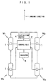
- Fig. 1 is a block diagram showing the construction of a tire pressure drop detecting device according to one embodiment of the present invention.
- Fig. 2 is a block diagram showing the electrical construction of a control device.
- Fig. 3 is a flow chart for explaining a tire pressure drop detecting processing.
- Fig. 4 is a flow chart for explaining the steps following those shown in Fig. 3.
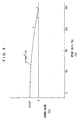
- Fig. 5 is a graph for explaining a judging threshold value used for an autocruise adapted processing.
- Fig. 6 is a graph for explaining a high-speed adapted judging processing.
- Fig. 1 is a schematic block diagram showing the construction of a tire pressure drop detecting device to which one embodiment of the present invention is applied.
- This tire pressure drop detecting device detects whether the pneumatic pressures of any one of four tires W 1 , W 2 , W 3 and W 4 provided for a four-tire vehicle drop or not, respectively.
- the tires W 1 and W 2 correspond to right front and left front tires
- the tires W 3 and W 4 correspond to right rear and left rear tires, respectively.
- This tire pressure drop detecting device is equipped with wheel speed sensors 1, which are associated with the tires W 1 , W 2 , W 3 and W 4 , respectively. Output signals of each of the wheel speed sensors 1 are supplied to a control unit 2.
- an initializing switch 4 is also connected to the control unit 2.
- the initial difference refers to a variation in effective rolling radius within the standard requirements, which arises among the respective tires W i .
- Fig. 2 is a block diagram showing the electrical construction of a tire pressure drop detecting device.
- the control unit 2 is composed of a micro computer including an I/O interface 2a, a CPU 2b, a ROM 2c, a RAM 2d and a counter 2e.
- the I/O interface 2a is required for sending and receiving signals to and from an external device including the wheel speed sensors 1 and the initializing switch 4.
- the CPU 2b is used for executing various operation processing according to a control program stored in the ROM 2c.
- the RAM 2d is that in which data, etc. are temporarily written to or the written data are read out from it when the CPU 2b performs a control or a calculation.
- the counter 2e stores a count value AC for a judgment whether the vehicle is autocruise driving or not.
- Each of the wheel speed sensors 1 generates pulse signals corresponding to the rotating speed of the corresponding tire W i (referred to as a "wheel speed pulses" hereinafter).
- Fig. 3 and Fig. 4 are flow charts for explaining the tire pressure drop detecting processing in the tire pressure drop detecting device.
- the CPU 2b operates according to a predetermined program stored in the ROM 2c so as to perform this processing by the function of control unit 2 for each judging period ⁇ T.
- the following description will be made with respect to an FF (front engine-front drive) vehicle by means of an example of an objective vehicle.
- the rotational angular velocity F i of each tire W i is firstly calculated based on the wheel speed pulses generated from each wheel speed sensor 1 (step S1).
- the tires W i have the initial differences within manufacturing tolerance. Accordingly, the effective rolling radiuses of the respective tires W i are not the same, necessarily, even if all tires W i have a normal inner pressure. Therefore, the rotational angular velocity F i of each tire W i may vary. On the other hand, the judgment whether the pneumatic pressure of any tire W i has dropped or not is executed on the assumption that the rotational angular velocities F i of the respective tires W i are almost the same when all tires W i have a normal inner pressure. Accordingly, it is necessary to exclude the influence of the initial difference from the rotational angular velocities F i .
- step S2 initial corrections on the rotational angular velocities F1 1 , F1 2 , F1 3 , and F1 4 .
- F1 3 K 3 x F 3
- F1 4 K 2 x K 3 x F 4
- An initial correction factor K 1 is a factor for correcting a difference in effective rolling radius due to the initial difference between the right front and left front tires W 1 , W 2 .
- An initial correction factor K 2 is a factor for correcting a difference in effective rolling radius due to the initial difference between the right rear and left rear tires W 3 , W 4 .
- An initial correction factor K 3 is a factor for correcting a difference in effective rolling radius due to the initial difference between the left front tire W 1 and left rear tire W 3 .
- the ROM2c is preferably composed of a programmable non-volatile memory such as an EPROM or an EEPROM.
- the variation in rotational angular velocities F i of the tires W i is not caused only by the initial difference.
- a difference in slip rate Rs between the right and left driving tires W 1 , W 2 when the vehicle is traveling through a corner is one of the causes.
- a lateral acceleration LA is exerted in the direction toward the outside of the corner and the load of the vehicle transfers toward the outside of the corner.
- the load applied on the tire on the inside to the corner relatively becomes small while the load applied on the tire on the outside to the corner relatively becomes large.
- the ground area of the tire on the inside to the corner relatively becomes small while the ground area of the tire on the outside to the corner comparatively becomes large.
- a driving force generated in the engine is given to the tire on the inside to the corner and the tire on the outside to the corner, almost uniformly, by a differential gear. Accordingly, a difference in slip rate Rs between the driving tires W 1 , W 2 arises. As a result, even if all tires W i have a normal inner pressure, a variation in rotational angular velocities between the tire on the inside to the corner and the tire on the outside to the corner arises.
- the calculated slip rate Rs is once stored in the RAM 2d. This slip rate Rs is used in case of correcting the judged value required for pneumatic pressure drop detection. That is, in case of correcting the judged value, the slip rate Rs of this driving tires W 1 , W 2 and the lateral acceleration LA of the vehicle are used. Consequently, the difference in slip rate of the right and left tires W i can be corrected.
- a difference in distance from the turning center between the tire on the inside to the corner and tire on the outside to the corner is also one of the causes of the variation in rotational angular velocities F i of the tires W i .
- the load movement of the vehicle is also a cause of the variation in rotational angular velocities F i .
- the turning radius R of the vehicle in which the influence of the load movement of the vehicle is excluded is calculated (step S4). More specifically, the speeds V1 3 and V1 4 of the following tires W 3 and W 4 are firstly calculated based on the rotational angular velocities F1 3 and F1 4 after initial correction, according to the following equations (8) and (9).
- r is a constant corresponding to the effective rolling radius at the time of the linear traveling.
- V1 3 r x F1 3
- V1 4 r x F1 4
- the turning radius R' of the vehicle is calculated based on the calculated speeds V1 3 and V1 4 of the following tires W 3 and W 4 , according to the following equation (10).
- Tw indicates a tread width as a distance between the following tires W 3 , W 4 .
- This calculated turning radius R' of the vehicle is subjected to the correction by which the variation caused by the load movement of the vehicle is excluded, according to the following equation (11), thereby determining a turning radius R of the vehicle after correction.
- R R' x ⁇ u 1 + u 2 (V1 3 + V1 4 ) 2 ⁇
- u 1 and u 2 respectively indicate a constant which is previously stored in the ROM 2c.
- u 1 and u 2 are obtained, for example, by traveling with a constant speed on the road wherein the turning radius of the vehicle is previously known.
- the rotational angular velocities F1 i determined in the above step S2 are corrected based on the determined turning radius R of the vehicle in order to exclude the variation caused by the difference in distance between the respective tires W i and the turning center (step S5).
- rotational angular velocities F2 1 to F2 4 after correction are determined according to the following equations (12) through (15).
- WB indicates a wheel base of the vehicle.
- F2 1
- F2 2
- F2 3
- F2 4
- the rotational angular velocity F i sometimes contain an error depending on the turning radius R of the vehicle, velocity V of the vehicle, lateral acceleration LA of the vehicle and magnitude of front/rear acceleration FRA i of each tire W i .
- step S6 the speed V1 of the vehicle, lateral acceleration LA and front/rear acceleration FRA i of each tire W i are calculated (step S6). More specifically, the speed V of the vehicle is calculated based on the speed V1 i of each tire W i .
- V1 (V1 1 + V1 2 + V1 3 + V1 4 )/4
- the front/rear acceleration FRA i of each tire W i is calculated according to the following equation (19) assuming the speed of each tire W i calculated in the judging period before one period be BV1 i .
- FRA i (V1 i - BV1 i )/( ⁇ T x 9.8)
- the numeral 9.8 in the denominator in the above equations (18) and (19) converts the lateral front/rear acceleration LA and the front/rear acceleration FRA i of each tire W i in gravity acceleration unit basis.
- the speed V1 of the vehicle, lateral acceleration LA and front/rear acceleration FRA i of the vehicle may be directly determined by using sensors for detection thereof.
- step S7 On the basis of the turning radius R of the vehicle, velocity V of the vehicle, front/rear acceleration FRA i of each tire W i and lateral acceleration LA of the vehicle, it is judged whether the rotational angular velocities F i calculated at the time of this sampling should be rejected or not (step S7). Specifically, the rotational angular velocities F i are rejected if at least one of the following four conditions 1 ⁇ to 4 ⁇ is satisfied:
- the rotational angular velocities F2 i corrected according to the initial difference and difference in inner and outer wheels of the tire W i are used.
- the rotational angular velocities F i of the tires W i depend on not only initial difference and difference in inner and outer wheels, but also lateral acceleration LA and slip rate Rs. Accordingly, the influence of variable factors including the lateral acceleration LA and slip rate Rs is exerted on the judged value D1 determined in the step S8.
- step S9 the correction for excluding the influence of the above variable factors on the judged value D1 calculated in the step S8 is carried out (step S9). Specifically, a corrected value C is determined based on the slip rate Rs determined in the step S3 and the lateral acceleration LA of the vehicle determined in the step S6 according to the following equation (21). Then, as shown in the following equation (22), the corrected value C is subtracted from the judged value D1. Consequently, a new judged value D2 wherein the influence of the above variable factors is excluded is obtained.
- ⁇ 1 and ⁇ 2 respectively indicate factors which are previously restored in the ROM 2c.
- the factors ⁇ 1 and ⁇ 2 are determined by performing a test traveling when it is known that all the tires W i have a normal inner pressure.
- step S9 it is judged whether a tire W i whose pneumatic pressure has dropped is present or not using this judged value D2 (step S10). Specifically, it is discriminated whether the judged value D2 satisfies the following expression (23) or not.
- the judged value D2 satisfies the above expression (23) If the judged value D2 satisfies the above expression (23), it is judged that the pneumatic pressure of at least one of the tires W i has dropped, and a low-speed alarm flag for giving/stopping of an alarm is set. On the other hand, if the judged value D2 does not satisfy the above expression (23), it is judged that there is no tire whose pneumatic pressure has dropped, and a low-speed alarm flag is reset.
- the judged value D2 becomes a comparatively large value as in case of the low-speed traveling and the pressure drop can be accurately judged in the above judgment of the step S10. Therefore, the above judgment of the step 10 will suffice in such case.
- step S11 of Fig. 4 it is discriminated whether the vehicle is in a state of high-speed drive traveling or not. If the vehicle is in a state of high-speed drive traveling, the high-speed adaptation judging processing is executed (step S12).
- V TH 120 km/h
- a TH 0 g
- the high-speed adapted judging processing it is determined that the speed V of the vehicle at the time when the judged value D2 is calculated, belongs to which one of a plurality of previously set speed ranges, and the judged value D2 is classified into the speed range thus determined.
- the average value of the judged values D2 in the corresponding speed range is calculated and the corresponding average values are plotted in a graph as shown in Fig. 6. Then, these plots are subjected to a regression processing by the least squares method.
- the judged value CrosP satisfies the judging expression, it is judged that a tire W i whose pneumatic pressure has dropped is present and a high-speed alarm flag for indicating the giving/stopping of the alarm is set. On the other hand, if the judged value CrosP does not satisfy the judging expression, it is judged that all tires W i have a normal inner pressure, and a high-speed flag is reset.
- the average value of the judged values D2 corresponding to three or more speed ranges is required. That is, even if the vehicle is in a state of high-speed drive traveling, it is impossible to correctly judge the pneumatic pressure drop by the above-described high-speed adaptated judging processing if the speed of the vehicle does not vary.
- an autocruise adapted processing as a pneumatic pressure drop judging processing for autocruise traveling is executed (steps S13 to S21).
- the autocruise adaptated processing is classified roughly into a pre-processing and a processing for executing the pneumatic pressure drop judging processing for autocruising.
- the pre-processing is a processing for collecting data which is required to execute the pneumatic pressure drop judging processing for autocruising, while judging whether the vehicle is aotocruise traveling or not.
- a TH 0.025 g
- step S13 it is discriminated whether the absolute value of the front/rear acceleration FRA of the vehicle is not more than the threshold value A TH (step S13). If the absolute value of the front/rear acceleration FRA is larger than the threshold value A TH , it is judged that the vehicle is not autocruise traveling and a count value AC of the counter 2e is cleared (step S15). On the other hand, if the absolute value of the front/rear acceleration FRA is smaller than the threshold value A TH , it is judged that there is a possibility that the vehicle is in a state of autocruise traveling and a count value AC of the counter 2e is incremented (step S14).
- the count value AC of the counter 2e increases when the vehicle is in a state of autocruise traveling and, if not, it is cleared. Accordingly, when the count value AC of the counter 2e is not less than a predetermined value (e.g. 60), it is possible to discriminate that the vehicle is in a state of autocruise traveling.
- a predetermined value e.g. 60
- step S7 when the vehicle is not traveling linearly (not traveling at the corner), an error is included in the judged value D2. This error can be ignored in the reject processing (step S7) and the correction processing (step S9) which are performed before the autocruise adaptated processing is executed, but can not be ignored in the autocruise adaptated processing. Because the threshold value used in case of the pneumatic pressure drop judgment may be a variable value in the autocruise adaptation processing, as described hereinafter.
- the step transfers to the pneumatic pressure drop judging processing for autocruising.
- the judged value D2 and the speed V1 of the vehicle are substantially constant.
- the judged value D2 and the speed V1 of the vehicle may sometimes include an error by an unexpected noise.
- the judged value D2 and the speed V1 of the vehicle are leveled or smoothed to calculate a judged value D3 and a speed V2 of the vehicle, wherein the error is excluded.
- step S19 the speed V2 of the vehicle is calculated according to the following equation (25) (step S19).
- V2 V1 .
- V2 (59/60) x V2 + (1/60) x V1
- a judging threshold value D HTH is set to become smaller as the speed V2 of the vehicle becomes larger. More specifically, the judging threshold value D HTH is set corresponding to the speed V2 of the vehicle classified into three stages such as 0 to V TH1 , V TH1 to V TH2 and V TH2 or more, as shown in Fig. 5. More specifically, the judging threshold value D HTH is set as shown in the following equations (26) to (28). The following equations (26) to (28) are previously stored in the ROM 2c. ⁇ 1 and ⁇ 2 respectively indicate predetermined constants.
- D HTH D HTH1 (V2 ⁇ V TH1 )
- D HTH ⁇ 1 x V1 + ⁇ 2 (V TH1 ⁇ V2 ⁇ V TH2 )
- D HTH D HTH2 (V2 ⁇ V TH2 )
- step S20 it is examined that the calculated speed V2 of the vehicle belongs to which one of stages, and a judging threshold value corresponding to the results is read out (step S20).
- D HTH1 may be set to 0.1
- V TH1 may be set to 120 (km/h)
- V TH2 may be set to 200 (km/h).
- D TH2 is set to a value wherein an erroneous judgment is not caused even in case of linear traveling in the state where all tires W i have a normal inner pressure, for example, it is set to 0.03.
- the alarm giving/stopping processing is executed (step S22).
- the alarm giving/stopping processing it is discriminated whether any one of the low-speed alarm flag, high-speed alarm flag and autocruise alarm flag is set or not. As a result, if any one of the above three flags is set, an alarm signal is given to the indicator 3.
- the indicator 3 when the alarm signal is given, a indication lamp provided for the indicator 3 is switched on. Consequently, it is informed that the pneumatic pressure of any of the tires W i has dropped.
- the tire pressure drop detecting device of the present embodiment when the vehicle is in a state of autocruise traveling, the autocruise adaptated processing for autocruise traveling is executed based on the judged value D3, which is determined when the vehicle is traveling almost linearly and further subjected to a leveling processing, and the judging threshold value D HTH set to becomes smaller as the speed becomes higher. Accordingly, even if the vehicle is in a state of autocruise traveling at high speed range, it is possible to certainly detect that the pneumatic pressure of any of the tires W i has dropped. Therefore, a tire pressure drop detecting device with high accuracy can be obtained.
Abstract

Description
Claims (14)
- A tire pressure drop detecting method, comprising the steps of:detecting (S1) the angular velocities (Fi) of the tires provided on a vehicle,discriminating (S13-S17) whether the vehicle is in a state of autocruise traveling or not, andexecuting a pneumatic pressure drop judging processing (S18-21) for autocruise traveling based on the detected angular velocities (Fi) when it is discriminated that the vehicle is in a state of autocruise traveling.
- A method according to Claim 1, further comprising the step of detecting (S6) a front/rear acceleration of the vehicle based on the detected angular velocities (Fi),
wherein the step (S13-S17) of discriminating whether the vehicle is in a state of autocruise traveling or not includes the step of performing the discrimination based on the detected front/rear acceleration of the vehicle. - A method according to Claim 1 or 2, further comprising the steps of:calculating (S18) a judged value (D3) based on the detected angular velocities (Fi),calculating (S19) the speed (V2) of the vehicle based on the rotational angular velocities (Fi),
wherein the step of executing the pneumatic pressure drop judging processing (S18-S21) for autocruise driving includes the steps of:obtaining (S20) a judging threshold value (DHTH) corresponding to the calculated speed (V2) of the vehicle among judging threshold values which are set to become smaller as the speed of the vehicle becomes larger, andjudging (S21) whether the tire pressure has dropped or not based on this obtained judging threshold value (DHTH) and the calculated judged value (D3). - A method according to Claim 1 or 2, further comprising the steps of:calculating (S18) a judged value (D3) based on the detected angular velocities (Fi),calculating (S19) the speed (V2) of the vehicle based on the detected angular velocities (Fi),calculating (S6) a lateral acceleration (LA) of the vehicle based on the detected angular velocities (Fi),discriminating (S16) whether an absolute value of this calculated lateral acceleration (LA) of the vehicle is less than a predetermined acceleration threshold value (LATH), andholding the calculated judged value (LA) when it is judged that the absolute value of the lateral acceleration of the vehicle is less than the acceleration threshold value (LATH),
wherein the step (S18-S21) of executing the pneumatic pressure drop judging processing for autocruise traveling includes the steps of:leveling (S18) the held judged value (D3),obtaining (S20) a judging threshold value (DHTH) corresponding to the calculated speed (V2) of the vehicle among judging threshold values which are set to become smaller as the speed of the vehicle becomes larger, andjudging (S21) whether the tire pressure has dropped or not based on this obtained judging threshold value (DHTH) and the leveled judged value (D3). - A method according to Claim 4, further comprising the steps of:holding the calculated speed (V2) of the vehicle when it is judged that the absolute value (LA) of the lateral acceleration of the vehicle is less than the acceleration threshold value (LATH), andleveling (S19) the held speed (V2) of the vehicle,
wherein the step (S20) of obtaining the judging threshold value includes the step of obtaining the judging threshold value (DHTH) corresponding to the leveled speed (V2) of the vehicle. - A method according to any one of the Claims 1 to 4, further comprising the step of:calculating (S8) a judged value (D1) based on the detected angular velocities (Fi), anda low-speed adapted judging step (S10) of judging whether the tire pressure has dropped or not by comparing this judged value (D1) with a constant threshold value for low-speed traveling.
- A method according to any one of the Claims 1 to 6, further comprising the steps of:calculating (S9) a judged value (D2) based on the detected angular velocities (Fi),discriminating (S11) whether the vehicle is in a state of high-speed drive traveling or not, anda high-speed adaptation judging step (S12) of assuming a judged value (D2) in case that the speed (V1) of the vehicle is nearly zero baed on the above calculated judged value (D2) when it is discriminated that the vehicle is in a state of high-speed drive traveling, and judging (S12) whether the tire pressure has dropped or not based on the assumed judged value.
- A tire pressure drop detecting device, comprising:angular velocity detecting means (1) for detecting the angular velocities (Fi) of the tires provided on a vehicle,autocruise discriminating means (S13-S17) for discriminating whether the vehicle is in a state of autocruise traveling or not, andprocessing executing means (S18-S21) for executing a pneumatic pressure drop judging processing for autocruise traveling based on the angular velocities (Fi) detected by the angular velocity detecting means (1) when it is discriminated that the vehicle is in a state of autocruise traveling.
- A tire pressure drop detecting device according to Claim 8, further comprising front/rear acceleration detecting means (S6) for detecting a front/rear acceleration of the vehicle,
wherein the autocruise discriminating means (S13-S17) discriminate whether the vehicle is in a state of autocruise traveling or not based on the detected front/rear acceleration. - A tire pressure drop detecting device according to Claim 8 or 9, further comprising:judged value operating means (S18) for calculating a judged value (D3) based on the angular velocities (Fi) detected by the angular velocity detecting means (1), andspeed calculating means (S19) for calculating the speed (V2) of the vehicle based on the angular velocities (Fi) detected by the angular velocity detecting means (1),obtaining means (S20) for obtaining a judging threshold value (DHTH) corresponding to the speed of the vehicle calculated by the speed calculating means (S19) among judging threshold values which are set to become smaller as the speed of the vehicle becomes larger, andjudging means (S21) for judging whether the tire pressure has dropped or not based on the judging threshold value (DHTH) obtained by the obtaining means (S20) and the judged value (D3) calculated by the judged value operating means (S18).
- A tire pressure drop detecting device according to Claim 8 or 9, further comprising:judged value operating means (S18) for calculating a judged value (D3) based on the angular velocities (Fi) detected by the angular velocity detecting means (1),speed calculating means (S19) for calculating the speed (V2) of the vehicle based on the angular velocities (Fi) detected by the angular velocity detecting means (1),lateral acceleration operating means (S6) for calculating a lateral acceleration (LA) of the vehicle based on the angular velocities (Fi) detected by the angular velocity detecting means (1),acceleration discriminating means (S16) for discriminating whether an absolute value of the lateral acceleration (LA) of the vehicle calculated by the lateral acceleration operating means (S6) is less than a predetermined acceleration threshold value (LATH), andjudged value holding means (2d) for holding the judged value (D3) calculated by the judged value operating means (S18) when it is judged by the acceleration discriminating means (S16) that the absolute value of the lateral acceleration (LA) of the vehicle is less than the acceleration threshold value (LATH),
wherein the processing executing means includes:leveling means (S18) for leveling the judged value (D3) held by the holding means (2d) and the speed (V2) of the vehicle,judging threshold value obtaining means (S20) for obtaining a judging threshold value (DHTH) corresponding to the speed of the vehicle among judging threshold values which are set to become smaller as the speed of the vehicle becomes larger, andjudging means (S21) for judging whether the tire pressure has dropped or not based on the judging threshold value (DHTH) and the judged value (D3) leveled by the leveling means. - A tire pressure drop detecting device according to Claim 11, further comprising:speed holding means (2d) for holding the calculated speed (V2) of the vehicle when it is judged that the absolute value (LA) of the lateral acceleration of the vehicle is less than the acceleration threshold value (LATH), andspeed leveling means (S19) for leveling the held speed (V2) of the vehicle,
wherein the judging threshold value obtaining means (S20) obtains a judging threshold value (DHTH) corresponding to the leveled speed of the vehicle. - A tire pressure drop detecting device according to any one of Claims 8 to 12, further comprising:judged value calculating means (S8, S9) for calculating a judged value (D1) based on the detected angular velocities (Fi), andlow-speed adapted judging means (S10) for judging whether the tire pressure has dropped or not by comparing this calculated judged value (D1) with a constant threshold value for low-speed traveling.
- A tire pressure drop detecting device according to any one of the Claims 8 to 13, further comprising:judged value calculating means (S8, S9) for calculating a judged value (D2) based on the detected angular velocities (Fi),high-speed drive discriminating means (S11) for discriminating whether the vehicle is in a state of high-speed drive traveling or not, andhigh-speed adapted judging means (S12) for assuming a judged value (D2) in case that the speed (V1) of the vehicle is nearly zero based on the above calculated judged value (D2) when it is discriminated that the vehicle is in a state of high-speed drive traveling, and judging (S11) whether the tire pressure has dropped or not based on the assumed judged value (D2).
Applications Claiming Priority (3)
| Application Number | Priority Date | Filing Date | Title |
|---|---|---|---|
| JP25575096 | 1996-09-27 | ||
| JP255750/96 | 1996-09-27 | ||
| JP25575096A JP3724892B2 (en) | 1996-09-27 | 1996-09-27 | Tire pressure drop detection method and apparatus |
Publications (3)
| Publication Number | Publication Date |
|---|---|
| EP0832767A2 true EP0832767A2 (en) | 1998-04-01 |
| EP0832767A3 EP0832767A3 (en) | 2000-09-06 |
| EP0832767B1 EP0832767B1 (en) | 2003-07-02 |
Family
ID=17283117
Family Applications (1)
| Application Number | Title | Priority Date | Filing Date |
|---|---|---|---|
| EP97116668A Expired - Lifetime EP0832767B1 (en) | 1996-09-27 | 1997-09-24 | Method of and device for detecting tire pressure drop |
Country Status (4)
| Country | Link |
|---|---|
| US (1) | US5907097A (en) |
| EP (1) | EP0832767B1 (en) |
| JP (1) | JP3724892B2 (en) |
| DE (1) | DE69723186T2 (en) |
Cited By (9)
| Publication number | Priority date | Publication date | Assignee | Title |
|---|---|---|---|---|
| FR2785574A1 (en) | 1998-11-10 | 2000-05-12 | Jean Claude Galland | Detection of deflation of tyres while vehicle is in motion using difference in distance travelled by each wheel |
| US6222444B1 (en) | 2000-04-03 | 2001-04-24 | Robert Bosch Corporation | Method for detecting a deflated tire on a vehicle |
| US6285280B1 (en) | 2000-06-26 | 2001-09-04 | Robert Bosch Corporation | Method for detecting a deflated tire on a vehicle |
| US6459369B1 (en) | 2000-11-22 | 2002-10-01 | Robert Bosch Corporation | Tire deflation detection system with feedback component |
| EP1190874A3 (en) * | 2000-09-20 | 2003-11-26 | Sumitomo Rubber Industries Ltd. | Apparatus and method for alarming decrease in tyre air pressure |
| EP1582380A2 (en) * | 2004-03-31 | 2005-10-05 | Sumitomo Rubber Industries Limited | Tire deflation warning system |
| US7289930B2 (en) | 2003-08-14 | 2007-10-30 | Continental Teves Ag & Co., Ohg | Method for monitoring tyre pressure monitoring systems in a motor vehicle |
| EP2085255A1 (en) * | 2008-01-31 | 2009-08-05 | Renault | Method for calibrating a signal for detecting a puncture in a vehicle tyre |
| WO2019231373A1 (en) * | 2018-05-31 | 2019-12-05 | Scania Cv Ab | Method, control unit, computer program product and carrier for identifying low tire pressure in a vehicle |
Families Citing this family (8)
| Publication number | Priority date | Publication date | Assignee | Title |
|---|---|---|---|---|
| DE19803386A1 (en) * | 1998-01-29 | 1999-08-05 | Daimler Chrysler Ag | Device for monitoring the air pressure of a vehicle tire |
| DE60021993T2 (en) * | 1999-12-09 | 2006-03-23 | Sumitomo Electric Industries, Ltd. | Apparatus and method for detecting a pressure drop in the tire |
| US8266465B2 (en) | 2000-07-26 | 2012-09-11 | Bridgestone Americas Tire Operation, LLC | System for conserving battery life in a battery operated device |
| US7161476B2 (en) | 2000-07-26 | 2007-01-09 | Bridgestone Firestone North American Tire, Llc | Electronic tire management system |
| JP2003267012A (en) * | 2002-01-09 | 2003-09-25 | Sumitomo Rubber Ind Ltd | Detecting method of decrease of tire air pressure, its device, and program of determining tire decompression |
| JP3834261B2 (en) * | 2002-05-10 | 2006-10-18 | 住友ゴム工業株式会社 | Tire pressure drop detection method and apparatus, and tire decompression determination program |
| DE102007029870A1 (en) * | 2007-06-28 | 2009-01-02 | Continental Teves Ag & Co. Ohg | Tire condition monitoring method and apparatus |
| JP2024011301A (en) * | 2022-07-14 | 2024-01-25 | トヨタ自動車株式会社 | Information processing apparatus, vehicle equipped with the same, information processing method, and program |
Citations (2)
| Publication number | Priority date | Publication date | Assignee | Title |
|---|---|---|---|---|
| EP0291217B1 (en) * | 1987-05-13 | 1991-05-22 | Sp Tyres Uk Limited | A method of detecting a deflated tyre on a vehicle |
| JPH08216636A (en) * | 1995-02-17 | 1996-08-27 | Nissan Motor Co Ltd | Apparatus for detecting inner pressure drop of tire |
Family Cites Families (7)
| Publication number | Priority date | Publication date | Assignee | Title |
|---|---|---|---|---|
| GB9002925D0 (en) * | 1990-02-09 | 1990-04-04 | Sumitomo Rubber Ind | Method of detecting a deflated tyre on a vehicle |
| GB9109466D0 (en) * | 1991-05-02 | 1991-06-26 | Sumitomo Rubber Ind | A method of detecting a deflated tyre on a vehicle |
| JP3032092B2 (en) * | 1992-12-21 | 2000-04-10 | 住友ゴム工業株式会社 | Automatic initial setting method for a device that detects abnormal air pressure from changes in tire angular velocity |
| JPH08164720A (en) * | 1994-12-15 | 1996-06-25 | Sumitomo Electric Ind Ltd | Tire air pressure reduction detecting method and tire air pressure reduction detecting device |
| US5569848A (en) * | 1995-01-06 | 1996-10-29 | Sharp; Everett H. | System, method and apparatus for monitoring tire inflation pressure in a vehicle tire and wheel assembly |
| US5604307A (en) * | 1995-02-01 | 1997-02-18 | Sumitomo Rubber Industries, Ltd. | Tire pressure drop alarm device sensing partial travel on irregular road surface |
| GB9504217D0 (en) * | 1995-03-02 | 1995-04-19 | Sumitomo Rubber Ind | A method of determining the inflation pressure of a tyre on a moving vehicle |
-
1996
- 1996-09-27 JP JP25575096A patent/JP3724892B2/en not_active Expired - Lifetime
-
1997
- 1997-09-08 US US08/925,087 patent/US5907097A/en not_active Expired - Lifetime
- 1997-09-24 EP EP97116668A patent/EP0832767B1/en not_active Expired - Lifetime
- 1997-09-24 DE DE69723186T patent/DE69723186T2/en not_active Expired - Lifetime
Patent Citations (2)
| Publication number | Priority date | Publication date | Assignee | Title |
|---|---|---|---|---|
| EP0291217B1 (en) * | 1987-05-13 | 1991-05-22 | Sp Tyres Uk Limited | A method of detecting a deflated tyre on a vehicle |
| JPH08216636A (en) * | 1995-02-17 | 1996-08-27 | Nissan Motor Co Ltd | Apparatus for detecting inner pressure drop of tire |
Non-Patent Citations (1)
| Title |
|---|
| PATENT ABSTRACTS OF JAPAN vol. 1996, no. 12, 26 December 1996 (1996-12-26) & JP 08 216636 A (NISSAN MOTOR CO LTD), 27 August 1996 (1996-08-27) & US 5 670 716 A (TORII SHUJI ET EL) 23 September 1997 (1997-09-23) * |
Cited By (11)
| Publication number | Priority date | Publication date | Assignee | Title |
|---|---|---|---|---|
| FR2785574A1 (en) | 1998-11-10 | 2000-05-12 | Jean Claude Galland | Detection of deflation of tyres while vehicle is in motion using difference in distance travelled by each wheel |
| US6222444B1 (en) | 2000-04-03 | 2001-04-24 | Robert Bosch Corporation | Method for detecting a deflated tire on a vehicle |
| US6285280B1 (en) | 2000-06-26 | 2001-09-04 | Robert Bosch Corporation | Method for detecting a deflated tire on a vehicle |
| EP1190874A3 (en) * | 2000-09-20 | 2003-11-26 | Sumitomo Rubber Industries Ltd. | Apparatus and method for alarming decrease in tyre air pressure |
| US6459369B1 (en) | 2000-11-22 | 2002-10-01 | Robert Bosch Corporation | Tire deflation detection system with feedback component |
| US7289930B2 (en) | 2003-08-14 | 2007-10-30 | Continental Teves Ag & Co., Ohg | Method for monitoring tyre pressure monitoring systems in a motor vehicle |
| EP1582380A2 (en) * | 2004-03-31 | 2005-10-05 | Sumitomo Rubber Industries Limited | Tire deflation warning system |
| EP1582380A3 (en) * | 2004-03-31 | 2007-05-02 | Sumitomo Rubber Industries Limited | Tire deflation warning system |
| EP2085255A1 (en) * | 2008-01-31 | 2009-08-05 | Renault | Method for calibrating a signal for detecting a puncture in a vehicle tyre |
| FR2927017A1 (en) * | 2008-01-31 | 2009-08-07 | Renault Sas | METHOD FOR CALIBRATING A TIRE DETECTING SIGNAL OF A TIRE OF A VEHICLE |
| WO2019231373A1 (en) * | 2018-05-31 | 2019-12-05 | Scania Cv Ab | Method, control unit, computer program product and carrier for identifying low tire pressure in a vehicle |
Also Published As
| Publication number | Publication date |
|---|---|
| JP3724892B2 (en) | 2005-12-07 |
| JPH10100621A (en) | 1998-04-21 |
| EP0832767A3 (en) | 2000-09-06 |
| US5907097A (en) | 1999-05-25 |
| DE69723186T2 (en) | 2004-04-22 |
| DE69723186D1 (en) | 2003-08-07 |
| EP0832767B1 (en) | 2003-07-02 |
Similar Documents
| Publication | Publication Date | Title |
|---|---|---|
| EP0786362B1 (en) | Method of and device for detecting tire pressure drop | |
| EP0712740B1 (en) | Method and device for calculating turning radius of vehicle taking load movement thereof into consideration | |
| EP0832767B1 (en) | Method of and device for detecting tire pressure drop | |
| US5629478A (en) | Method of and device for detecting tire pressure drop based on angular velocity | |
| US7194341B2 (en) | Method and device for determining the geometric vehicle inclination of a motor vehicle | |
| US5959202A (en) | Device for determining initial correction factor for correcting rotational velocity of tire | |
| US5604307A (en) | Tire pressure drop alarm device sensing partial travel on irregular road surface | |
| US6061642A (en) | Initial correction factor determining device and device utilizing the same for vehicle | |
| US5442331A (en) | Method and device for detecting a deflated tire by comparing angular velocity and forward/backward speed data with a data table | |
| GB2320788A (en) | Low tyre warning system | |
| EP2191987B1 (en) | Apparatus and method for detecting decrease in tire air pressure and program for detecting decrease in tire air pressure | |
| EP0861743B1 (en) | Device for calculating initial correction factor for correcting rotational angular velocity of tire | |
| EP2110269A1 (en) | Method and apparatus for detecting decrease in tire air pressure and program for determing decrease in tire air pressure | |
| KR19980076549A (en) | Method and apparatus for detecting tire pressure drop | |
| EP1223055A2 (en) | Tire pneumatic pressure detector | |
| EP1396356B1 (en) | Method and apparatus for detecting decrease in tire air-pressure and program for judging decompression of tire | |
| JP3129671B2 (en) | Method and apparatus for detecting decrease in tire air pressure | |
| JP3623023B2 (en) | Tire pressure drop detection method and apparatus | |
| JP3167278B2 (en) | Method and apparatus for detecting decrease in tire air pressure | |
| JP3585557B2 (en) | Method and apparatus for detecting decrease in tire air pressure |
Legal Events
| Date | Code | Title | Description |
|---|---|---|---|
| PUAI | Public reference made under article 153(3) epc to a published international application that has entered the european phase |
Free format text: ORIGINAL CODE: 0009012 |
|
| AK | Designated contracting states |
Kind code of ref document: A2 Designated state(s): DE FR GB |
|
| AX | Request for extension of the european patent |
Free format text: AL;LT;LV;RO;SI |
|
| PUAL | Search report despatched |
Free format text: ORIGINAL CODE: 0009013 |
|
| AK | Designated contracting states |
Kind code of ref document: A3 Designated state(s): AT BE CH DE DK ES FI FR GB GR IE IT LI LU MC NL PT SE |
|
| AX | Request for extension of the european patent |
Free format text: AL;LT;LV;RO;SI |
|
| 17P | Request for examination filed |
Effective date: 20001213 |
|
| AKX | Designation fees paid |
Free format text: DE FR GB |
|
| 17Q | First examination report despatched |
Effective date: 20020604 |
|
| GRAH | Despatch of communication of intention to grant a patent |
Free format text: ORIGINAL CODE: EPIDOS IGRA |
|
| GRAH | Despatch of communication of intention to grant a patent |
Free format text: ORIGINAL CODE: EPIDOS IGRA |
|
| GRAA | (expected) grant |
Free format text: ORIGINAL CODE: 0009210 |
|
| AK | Designated contracting states |
Designated state(s): DE FR GB |
|
| REG | Reference to a national code |
Ref country code: GB Ref legal event code: FG4D |
|
| REF | Corresponds to: |
Ref document number: 69723186 Country of ref document: DE Date of ref document: 20030807 Kind code of ref document: P |
|
| ET | Fr: translation filed | ||
| PLBE | No opposition filed within time limit |
Free format text: ORIGINAL CODE: 0009261 |
|
| STAA | Information on the status of an ep patent application or granted ep patent |
Free format text: STATUS: NO OPPOSITION FILED WITHIN TIME LIMIT |
|
| 26N | No opposition filed |
Effective date: 20040405 |
|
| PGFP | Annual fee paid to national office [announced via postgrant information from national office to epo] |
Ref country code: GB Payment date: 20150923 Year of fee payment: 19 |
|
| REG | Reference to a national code |
Ref country code: FR Ref legal event code: PLFP Year of fee payment: 20 |
|
| PGFP | Annual fee paid to national office [announced via postgrant information from national office to epo] |
Ref country code: DE Payment date: 20160920 Year of fee payment: 20 |
|
| PGFP | Annual fee paid to national office [announced via postgrant information from national office to epo] |
Ref country code: FR Payment date: 20160816 Year of fee payment: 20 |
|
| GBPC | Gb: european patent ceased through non-payment of renewal fee |
Effective date: 20160924 |
|
| PG25 | Lapsed in a contracting state [announced via postgrant information from national office to epo] |
Ref country code: GB Free format text: LAPSE BECAUSE OF NON-PAYMENT OF DUE FEES Effective date: 20160924 |
|
| REG | Reference to a national code |
Ref country code: DE Ref legal event code: R071 Ref document number: 69723186 Country of ref document: DE |