EP0832798A2 - Image recognition system - Google Patents
Image recognition system Download PDFInfo
- Publication number
- EP0832798A2 EP0832798A2 EP97306835A EP97306835A EP0832798A2 EP 0832798 A2 EP0832798 A2 EP 0832798A2 EP 97306835 A EP97306835 A EP 97306835A EP 97306835 A EP97306835 A EP 97306835A EP 0832798 A2 EP0832798 A2 EP 0832798A2
- Authority
- EP
- European Patent Office
- Prior art keywords
- screen
- recognition system
- image recognition
- transparent member
- image
- Prior art date
- Legal status (The legal status is an assumption and is not a legal conclusion. Google has not performed a legal analysis and makes no representation as to the accuracy of the status listed.)
- Granted
Links
Images


Classifications
-
- B—PERFORMING OPERATIONS; TRANSPORTING
- B60—VEHICLES IN GENERAL
- B60S—SERVICING, CLEANING, REPAIRING, SUPPORTING, LIFTING, OR MANOEUVRING OF VEHICLES, NOT OTHERWISE PROVIDED FOR
- B60S1/00—Cleaning of vehicles
- B60S1/02—Cleaning windscreens, windows or optical devices
- B60S1/04—Wipers or the like, e.g. scrapers
- B60S1/06—Wipers or the like, e.g. scrapers characterised by the drive
- B60S1/08—Wipers or the like, e.g. scrapers characterised by the drive electrically driven
- B60S1/0818—Wipers or the like, e.g. scrapers characterised by the drive electrically driven including control systems responsive to external conditions, e.g. by detection of moisture, dirt or the like
- B60S1/0822—Wipers or the like, e.g. scrapers characterised by the drive electrically driven including control systems responsive to external conditions, e.g. by detection of moisture, dirt or the like characterized by the arrangement or type of detection means
- B60S1/0833—Optical rain sensor
- B60S1/0844—Optical rain sensor including a camera
-
- G—PHYSICS
- G06—COMPUTING; CALCULATING OR COUNTING
- G06V—IMAGE OR VIDEO RECOGNITION OR UNDERSTANDING
- G06V10/00—Arrangements for image or video recognition or understanding
- G06V10/10—Image acquisition
- G06V10/12—Details of acquisition arrangements; Constructional details thereof
- G06V10/14—Optical characteristics of the device performing the acquisition or on the illumination arrangements
- G06V10/145—Illumination specially adapted for pattern recognition, e.g. using gratings
-
- G—PHYSICS
- G06—COMPUTING; CALCULATING OR COUNTING
- G06V—IMAGE OR VIDEO RECOGNITION OR UNDERSTANDING
- G06V20/00—Scenes; Scene-specific elements
- G06V20/50—Context or environment of the image
- G06V20/56—Context or environment of the image exterior to a vehicle by using sensors mounted on the vehicle
Definitions
- the present invention relates to an image recognition system, and in particular to an image recognition system for detecting liquid drops such as rain water drops deposited on a transparent member such as a windshield.
- Water drop sensors are conventionally known for automatically operating a windshield wiper upon detecting rain drops (water drops) deposited on the surface of a windshield of a vehicle. They include those using a base board which allows detection of water drop deposition by a change in the electric resistance of the base board, and those capturing and recognizing an image of the glass surface from inside the vehicle to detect the presence of water drops thereon.
- a primary object of the present invention is to provide an image recognition system which can be used for detecting liquid drops deposited on a transparent member both accurate and sensitive manner.
- a second object of the present invention is to provide an image recognition system which can accurately distinguish liquid drops deposited on a transparent member from solid depositions on the transparent member.
- a third object of the present invention is to provide an image recognition system which can accurately extract an image of liquid drops deposited on a surface of a transparent member from images of external objects.
- a fourth object of the present invention is to provide an image recognition system which can be used for accurately detecting rain drops on a windshield.
- an image recognition system for detecting liquid drops deposited on a surface of a transparent member, comprising: a screen placed over the transparent member or a part thereof; a camera for capturing an image formed on the screen from a reverse surface of the transparent member; and means for determining presence of liquid drops from the image captured by the camera.
- a screen placed over the transparent member or a part thereof
- a camera for capturing an image formed on the screen from a reverse surface of the transparent member
- means for determining presence of liquid drops from the image captured by the camera Owing to the use of the translucent screen, only the objects immediately near the screen such as liquid drops deposited on the transparent member are captured by the camera while the objects remote from the transparent member are disregarded. Also, solid smears deposited on the tranparent member can be distinguished from liquid drops by making use of the difference in optical properties of these two different objects.
- the screen may consist of a translucent sheet member placed over the inner or outer surface of the transparent member.
- the sheet member may also be placed between two layers of the transparent member.
- the translucent sheet member may consist of a frosted sheet member, a milky sheet member or a semi-transparent member as long as it allows detection of objects immediately near the screen while dispersing the light from objects remote from the transparent member. It is also possible to achieve a similar result by directly frosting a surface of the transparent member, for instance by physical or chemical means.
- the transparent member consists of a windshield glass sheet separating an interior of a vehicle from outside so that rain water drops deposited on the glass sheet may be detected.
- the camera may be placed behind a rearview mirror, while the screen is placed on an inner surface of the windshield glass sheet opposite the camera.
- the screen may be placed on a lower edge of on an inner surface of the windshield glass sheet while the camera is mount on a part of a dashboard opposing the screen.
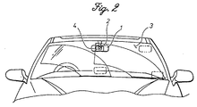
- FIG 1 shows the overall construction of a water drop detecting system for a vehicle which is incorporated with an image recognition system according to the present invention.
- a CCD camera 2 for capturing images is provided on a reverse side of a rearview mirror 1 provided inside a cabin of a vehicle.
- a screen 4 is placed on an upper middle part of a windshield 3 so as to be within the area swept by a wiper blade, to oppose the CCD camera 2, and not to obstruct the view of the vehicle occupants ( Figure 2).
- the screen 4 for instance consisting of a translucent film, such as milky film, translucent paper, frosted glass, is placed on the inner surface of the windshield 3 to disperse the light projected from some distance ahead of the screen 4, but relatively clealy shows through objects near the screen.
- a translucent film clearly shows though any objects immedicately next to the film, but virtualy obstruct the view of objects remote from the film.
- a hood 5 is placed over the space between the CCD camera 2 and the windshield 3 (screen 4) to shut off light from the sides, above or below, and to direct only the light from the screen 4 to the camera 2.
- the CCD camera 2 is connected to an image processing unit 6 which is in turn connected to a wiper drive control system which is not shown in the drawings.
- Figure 4 shows the waveform of an actually captured image.
- the CCD camera 2 sucessively captures an image at a regular interval or in synchronism with the sweeping strokes of the wiper blade (step 2). It is assumed that a water drop R and a smear D are deposited on the surface of the windshield 3, and that features corresponding to the water drop R and the smear D appear in the captured waverform.
- the first part of each cycle of the waveform is produced from the interal operation of the CCD camera 2, and the waveform of the actually captured signal is found in the range indicated by letter S.
- the captured signal is smoothed (step 2) to remove fine noises therefrom.
- the signal is then differentiated (step 3) to compute the change rate components of the signal.
- the obtained signal is converted into binary data with a threshold process (step 4) to allow determination of the presence and the quantity of water drops and smears.
- the operating mode of the windshield wiper is determined according to the detected signal, and the windshield wiper is controlled accordingly.
- the detected signal contains features due to the presence of the smear D, and, therefore, cannot be directly used for correctly recognizing the water drop R.
- the signal following the smoothing process of step 2 is subjected to a threshold process (step 5) based on a prescribed level, and then to a logical product process (step 7) with an enlarged signal (step 6) so that the features due to the smear D may be removed, and the binary data contains only the feature due to the water drop R.
- the enlargement process (step 6) advances the leading edge of the pulse produced by the presence of a smear and delays the trailing edge of the pulse so that the logical product process can be accuately carried out even when some time delay is produced between the two signal flow lines (the signal flow line of steps 3 and 4, and the signal flow line of steps 5 to 7).
- Figure 5 compares the signals obtained by the CCD camera for the case (a) where the image is captured by using the screen and the case (b) where the image is directly captured without using the screen.
- Figure 5(a) clearly indicates the changes in the signal due to the presence of the water drops, but Figure 5(b) includes such a large interference from the outside view that the determination of the presence of water drops is very difficult.
- the screen made of a milky translucent film was attached to the inner surface of the upper middle part of the windshield in the above described embodiment, a similar film may be placed on the outer surface of the windshield or between a pair of glass sheets. It is also possible to frost a surface of the windshield by physical means such as fine abrasive particles, or by chemical means such as a hydrogen fluoride etchant. Larger water drops form clearer images when the screen is placed on the outer surface of the windshield, but smaller water drops form clearer images when the screen is placed on the inner surface of the windshield because the water drops perform the function of lenses.
- the method for forming the screen is not limited by the placing of a film, but the screen may also be formed by direct vapor deposition on the windshield surface or by application of a heat cured coating over the surface of the windshield.
- the position of the screen may also be freely selected as long as it would not obstruct the view of the vehicle occupants, in particular that of the vehicle operator, as indicated by the imaginary lines in Figure 2.
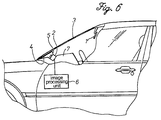
- the CCD camera 2 may be embedded inside the dashboard 7 so as not to obstruct the view of the vehicle occupants as shown in Figure 6.
- the image recognition system of the present invention was described as a rain drop detecting system for a vehicle such as a passenger car in the above embodiment, but the application of the present invention is not limited by the above described embodiment.
- the present invention can be applied to any applications where the state of liquid deposition on the surface of a transparent member is required to be determined.
- the screeen may be placed over the entire surface of the member so that the liquid drop detection may be carried out over the entire surface of the transparent member.
- a translucent screen is placed over a transparent member or a part thereof, the image showing through the screen is captured by a camera from the reverse surface of the transparent member, and the presence and the quantity of the liquid drops are determined from the captured image so that the image remote from the screen such as the external view showing through the transparent member are not captured, and only the liquid drops located immediately next to the screen are extracted.
- the sensitivity and the precision in detecting liquid drops deposited on a member can be improved by using a simple arrangement.
Abstract
Description
Claims (12)
- An image recognition system for detecting liquid drops deposited on a surface of a transparent member, comprising:a translucent screen placed over said transparent member or a part thereof;a camera for capturing an image formed on said screen from a reverse surface of said transparent member; andmeans for determining presence of liquid drops from the image captured by said camera.
- An image recognition system according to claim 1, wherein said screen comprises a translucent sheet member placed over said transparent member.
- An image recognition system according to claim 2, wherein said translucent sheet member comprises a frosted sheet member.
- An image recognition system according to claim 2, wherein said translucent sheet member comprises a semi-transparent sheet member.
- An image recognition system according to claim 2, wherein translucent sheet member comprises a milky sheet member.
- An image recognition system according to claim 1, wherein said transparent member consists of a windshield glass sheet separating an interior of a vehicle from outside so that rain water drops deposited on said glass sheet may be detected.
- An image recognition system according to claim 6, wherein said camera is placed on a reverse side of a rearview mirror, and said screen is placed on an inner surface of said windshield glass sheet opposite said camera.
- An image recognition system according to claim 6, wherein said screen is placed on a lower edge of on an inner surface of said windshield glass sheet, and said camera is mounted on a part of a dashboard opposing said screen.
- An image recognition system according to claim 2, wherein said translucent sheet member is placed over an inner surface of said transparent member.
- An image recognition system according to claim 2, wherein said translucent sheet member is laminated between two layers of said transparent member.
- An image recognition system according to claim 2, wherein said translucent sheet member is placed over an outer surface of said transparent member.
- An image recognition system according to claim 1, wherein said screen is formed by frosting a surface of said transparent member.
Applications Claiming Priority (3)
| Application Number | Priority Date | Filing Date | Title |
|---|---|---|---|
| JP26538696 | 1996-09-13 | ||
| JP265386/96 | 1996-09-13 | ||
| JP8265386A JPH1090188A (en) | 1996-09-13 | 1996-09-13 | Image recognition device |
Publications (3)
| Publication Number | Publication Date |
|---|---|
| EP0832798A2 true EP0832798A2 (en) | 1998-04-01 |
| EP0832798A3 EP0832798A3 (en) | 1998-12-02 |
| EP0832798B1 EP0832798B1 (en) | 2001-09-26 |
Family
ID=17416462
Family Applications (1)
| Application Number | Title | Priority Date | Filing Date |
|---|---|---|---|
| EP97306835A Expired - Lifetime EP0832798B1 (en) | 1996-09-13 | 1997-09-03 | Image recognition system |
Country Status (3)
| Country | Link |
|---|---|
| EP (1) | EP0832798B1 (en) |
| JP (1) | JPH1090188A (en) |
| DE (1) | DE69711725T2 (en) |
Cited By (20)
| Publication number | Priority date | Publication date | Assignee | Title |
|---|---|---|---|---|
| DE19749331A1 (en) * | 1997-11-07 | 1999-05-20 | Kostal Leopold Gmbh & Co Kg | Method of detecting objects on motor vehicle windscreen |
| WO1999038737A1 (en) * | 1998-01-30 | 1999-08-05 | Leopold Kostal Gmbh & Co. Kg | Method for detecting objects located on a transparent panel, and corresponding device |
| WO2000053466A1 (en) | 1999-03-06 | 2000-09-14 | Leopold Kostal Gmbh & Co. Kg | Optoelectronic monitoring device for a motor vehicle |
| WO2000053465A1 (en) | 1999-03-06 | 2000-09-14 | Leopold Kostal Gmbh & Co. Kg | Device for detecting objects on a windscreen of a motor vehicle |
| DE19909989A1 (en) * | 1999-03-06 | 2000-09-28 | Kostal Leopold Gmbh & Co Kg | Device for detecting objects on windshield of vehicle has object surface plane focused by objective that is oblique with respect to imaging axis of objective sensor array arrangement |
| DE19936262C1 (en) * | 1999-07-31 | 2001-02-15 | Kostal Leopold Gmbh & Co Kg | Structure for detecting rain and sunlight levels includes an internal motor vehicle rear-view mirror in a fastening arm, a chamber housing an optoelectronic sensor and a device to illuminate the inner side of a windscreen. |
| WO2001028813A2 (en) | 1999-10-16 | 2001-04-26 | Leopold Kostal Gmbh & Co. Kg | Optoelectronic sensor device for a motor vehicle |
| US6524968B2 (en) | 2001-07-06 | 2003-02-25 | Oki Electric Industry Co., Ltd. | Method for forming insulating film and for manufacturing integrated circuit |
| EP1334888A1 (en) * | 1997-09-16 | 2003-08-13 | Gentex Corporation | A vehicle windshield moisture detecting system |
| US6617564B2 (en) | 2001-10-04 | 2003-09-09 | Gentex Corporation | Moisture sensor utilizing stereo imaging with an image sensor |
| US6681163B2 (en) | 2001-10-04 | 2004-01-20 | Gentex Corporation | Moisture sensor and windshield fog detector |
| DE10322010A1 (en) * | 2003-05-16 | 2004-12-02 | Daimlerchrysler Ag | Image recognition system for detecting precipitation on motor vehicle screen uses defined area of vehicle surface detected by camera through screen as background for image acquisition, processing |
| EP1580092A2 (en) | 2004-03-26 | 2005-09-28 | Robert Bosch Gmbh | Camera in a vehicle |
| US7019275B2 (en) | 1997-09-16 | 2006-03-28 | Gentex Corporation | Moisture sensor and windshield fog detector |
| DE102005035812A1 (en) * | 2005-07-27 | 2007-02-08 | Adc Automotive Distance Control Systems Gmbh | Method of detecting soiling on a transparent pane |
| US9040915B2 (en) | 2009-07-06 | 2015-05-26 | Conti Temic Microelectronic Gmbh | Optical module for simultaneously focusing on two fields of view |
| US9335264B2 (en) | 2010-11-30 | 2016-05-10 | Conti Temic Microelectronic Gmbh | Detection of raindrops on a pane by means of a camera and lighting |
| US9508015B2 (en) | 2011-12-05 | 2016-11-29 | Continental Teves Ag & Co. Ohg | Method for evaluating image data of a vehicle camera taking into account information about rain |
| US9702818B2 (en) | 2012-05-03 | 2017-07-11 | Conti Temic Microelectronic Gmbh | Detection of raindrops on a windowpane by means of camera and light |
| US10137842B2 (en) | 2011-06-03 | 2018-11-27 | Conti Temic Microelectronic Gmbh | Camera system for a vehicle |
Families Citing this family (14)
| Publication number | Priority date | Publication date | Assignee | Title |
|---|---|---|---|---|
| US6822563B2 (en) | 1997-09-22 | 2004-11-23 | Donnelly Corporation | Vehicle imaging system with accessory control |
| US5877897A (en) | 1993-02-26 | 1999-03-02 | Donnelly Corporation | Automatic rearview mirror, vehicle lighting control and vehicle interior monitoring system using a photosensor array |
| US7655894B2 (en) | 1996-03-25 | 2010-02-02 | Donnelly Corporation | Vehicular image sensing system |
| JP4257627B2 (en) * | 1999-11-19 | 2009-04-22 | 日本精機株式会社 | Raindrop detector |
| US7038577B2 (en) | 2002-05-03 | 2006-05-02 | Donnelly Corporation | Object detection system for vehicle |
| DE10237606B4 (en) * | 2002-08-16 | 2006-04-27 | Hella Kgaa Hueck & Co. | Camera arrangement for motor vehicles |
| DE10237607B4 (en) * | 2002-08-16 | 2007-01-25 | Hella Kgaa Hueck & Co. | Camera arrangement for motor vehicles |
| DE10303047A1 (en) * | 2003-01-24 | 2004-08-05 | Daimlerchrysler Ag | Method and device for improving the visibility and for determining the weather situation |
| US7526103B2 (en) | 2004-04-15 | 2009-04-28 | Donnelly Corporation | Imaging system for vehicle |
| WO2008024639A2 (en) | 2006-08-11 | 2008-02-28 | Donnelly Corporation | Automatic headlamp control system |
| JP6182037B2 (en) * | 2013-09-30 | 2017-08-16 | 株式会社Subaru | Wiper washer equipment |
| CN103543638B (en) * | 2013-10-10 | 2015-10-21 | 山东神戎电子股份有限公司 | A kind of rain brush control method automatically |
| US20150124094A1 (en) * | 2013-11-05 | 2015-05-07 | Delphi Technologies, Inc. | Multiple imager vehicle optical sensor system |
| DE102021113065A1 (en) | 2021-05-20 | 2022-11-24 | Valeo Schalter Und Sensoren Gmbh | RAIN SENSING SYSTEM, VEHICLE AND METHOD FOR DETECTING RAIN |
Family Cites Families (4)
| Publication number | Priority date | Publication date | Assignee | Title |
|---|---|---|---|---|
| JPS6338058A (en) * | 1986-08-04 | 1988-02-18 | Nippon Denso Co Ltd | Controller for windshield wiper |
| IT212441Z2 (en) * | 1987-07-31 | 1989-07-04 | Veglia Borletti Srl | DEVICE SENSOR OF THE PRESENCE OF DROPS OF WATER ON A VEHICLE CRYSTAL AND EQUIPMENT OF A WINDSCREEN WIPER EQUIPPED WITH THE SAID DEVICE |
| JPH05126530A (en) * | 1991-11-08 | 1993-05-21 | Asmo Co Ltd | Instrument for measuring and processing spraying area of liquid |
| JPH09189533A (en) * | 1996-01-11 | 1997-07-22 | Tokai Rika Co Ltd | Deposit sensor and deposit-sensitive wiper |
-
1996
- 1996-09-13 JP JP8265386A patent/JPH1090188A/en active Pending
-
1997
- 1997-09-03 DE DE69711725T patent/DE69711725T2/en not_active Expired - Fee Related
- 1997-09-03 EP EP97306835A patent/EP0832798B1/en not_active Expired - Lifetime
Non-Patent Citations (1)
| Title |
|---|
| None |
Cited By (30)
| Publication number | Priority date | Publication date | Assignee | Title |
|---|---|---|---|---|
| EP1334888A1 (en) * | 1997-09-16 | 2003-08-13 | Gentex Corporation | A vehicle windshield moisture detecting system |
| US7019275B2 (en) | 1997-09-16 | 2006-03-28 | Gentex Corporation | Moisture sensor and windshield fog detector |
| DE19749331A1 (en) * | 1997-11-07 | 1999-05-20 | Kostal Leopold Gmbh & Co Kg | Method of detecting objects on motor vehicle windscreen |
| WO1999038737A1 (en) * | 1998-01-30 | 1999-08-05 | Leopold Kostal Gmbh & Co. Kg | Method for detecting objects located on a transparent panel, and corresponding device |
| WO2000053465A1 (en) | 1999-03-06 | 2000-09-14 | Leopold Kostal Gmbh & Co. Kg | Device for detecting objects on a windscreen of a motor vehicle |
| DE19909989A1 (en) * | 1999-03-06 | 2000-09-28 | Kostal Leopold Gmbh & Co Kg | Device for detecting objects on windshield of vehicle has object surface plane focused by objective that is oblique with respect to imaging axis of objective sensor array arrangement |
| DE19909987A1 (en) * | 1999-03-06 | 2000-09-28 | Kostal Leopold Gmbh & Co Kg | Arrangement for detecting objects located on a windshield of a motor vehicle |
| DE19909989B4 (en) * | 1999-03-06 | 2006-09-28 | Leopold Kostal Gmbh & Co. Kg | Device for detecting objects located on a transparent pane |
| US6841767B2 (en) | 1999-03-06 | 2005-01-11 | Leopold Kostal Gmbh & Co. Kg | Device for detecting objects on a windscreen of a motor vehicle |
| US6975390B2 (en) | 1999-03-06 | 2005-12-13 | Leopold Kostal Gmbh & Co. Kg | Optoelectronic monitoring device for a motor vehicle |
| DE19909987C2 (en) * | 1999-03-06 | 2003-04-10 | Kostal Leopold Gmbh & Co Kg | Arrangement for detecting objects located on a windshield of a motor vehicle |
| WO2000053466A1 (en) | 1999-03-06 | 2000-09-14 | Leopold Kostal Gmbh & Co. Kg | Optoelectronic monitoring device for a motor vehicle |
| DE19936262C1 (en) * | 1999-07-31 | 2001-02-15 | Kostal Leopold Gmbh & Co Kg | Structure for detecting rain and sunlight levels includes an internal motor vehicle rear-view mirror in a fastening arm, a chamber housing an optoelectronic sensor and a device to illuminate the inner side of a windscreen. |
| WO2001028813A2 (en) | 1999-10-16 | 2001-04-26 | Leopold Kostal Gmbh & Co. Kg | Optoelectronic sensor device for a motor vehicle |
| DE19950060A1 (en) * | 1999-10-16 | 2001-05-03 | Kostal Leopold Gmbh & Co Kg | Optoelectronic sensor device for a motor vehicle |
| DE19950060C2 (en) * | 1999-10-16 | 2003-01-16 | Kostal Leopold Gmbh & Co Kg | Optoelectronic sensor device for a motor vehicle |
| US6524968B2 (en) | 2001-07-06 | 2003-02-25 | Oki Electric Industry Co., Ltd. | Method for forming insulating film and for manufacturing integrated circuit |
| US6861636B2 (en) | 2001-10-04 | 2005-03-01 | Gentex Corporation | Moisture sensor utilizing stereo imaging with an image sensor |
| US6681163B2 (en) | 2001-10-04 | 2004-01-20 | Gentex Corporation | Moisture sensor and windshield fog detector |
| US6853897B2 (en) | 2001-10-04 | 2005-02-08 | Gentex Corporation | Windshield fog detector |
| US6617564B2 (en) | 2001-10-04 | 2003-09-09 | Gentex Corporation | Moisture sensor utilizing stereo imaging with an image sensor |
| DE10322010A1 (en) * | 2003-05-16 | 2004-12-02 | Daimlerchrysler Ag | Image recognition system for detecting precipitation on motor vehicle screen uses defined area of vehicle surface detected by camera through screen as background for image acquisition, processing |
| EP1580092A2 (en) | 2004-03-26 | 2005-09-28 | Robert Bosch Gmbh | Camera in a vehicle |
| DE102005035812A1 (en) * | 2005-07-27 | 2007-02-08 | Adc Automotive Distance Control Systems Gmbh | Method of detecting soiling on a transparent pane |
| US8274562B2 (en) | 2005-07-27 | 2012-09-25 | Adc Automotive Distance Control Systems Gmbh | Method for identifying soiling on a transparent screen |
| US9040915B2 (en) | 2009-07-06 | 2015-05-26 | Conti Temic Microelectronic Gmbh | Optical module for simultaneously focusing on two fields of view |
| US9335264B2 (en) | 2010-11-30 | 2016-05-10 | Conti Temic Microelectronic Gmbh | Detection of raindrops on a pane by means of a camera and lighting |
| US10137842B2 (en) | 2011-06-03 | 2018-11-27 | Conti Temic Microelectronic Gmbh | Camera system for a vehicle |
| US9508015B2 (en) | 2011-12-05 | 2016-11-29 | Continental Teves Ag & Co. Ohg | Method for evaluating image data of a vehicle camera taking into account information about rain |
| US9702818B2 (en) | 2012-05-03 | 2017-07-11 | Conti Temic Microelectronic Gmbh | Detection of raindrops on a windowpane by means of camera and light |
Also Published As
| Publication number | Publication date |
|---|---|
| EP0832798A3 (en) | 1998-12-02 |
| DE69711725T2 (en) | 2002-09-05 |
| DE69711725D1 (en) | 2002-05-08 |
| JPH1090188A (en) | 1998-04-10 |
| EP0832798B1 (en) | 2001-09-26 |
Similar Documents
| Publication | Publication Date | Title |
|---|---|---|
| EP0832798A2 (en) | Image recognition system | |
| US8541732B2 (en) | Optical module having a multifocal optical system with an additional optical element for covering a far range and a near range in one image | |
| US5923027A (en) | Moisture sensor and windshield fog detector using an image sensor | |
| US9616851B2 (en) | Method and apparatus for recognizing directional structures on a window pane of a vehicle | |
| KR100907625B1 (en) | Transmission detector for window body and cleaning system for field of view of the window body | |
| JP7272226B2 (en) | Raindrop Recognition Device, Vehicle Control Device, Learning Method and Trained Model | |
| US10106126B2 (en) | Apparatus and method for detecting precipitation for a motor vehicle | |
| JP2004538481A6 (en) | Transmission detector for window part and cleaning device for visual field area of window part | |
| CN102566212B (en) | Camera system and the method for running the camera system of motor vehicles | |
| US7208962B2 (en) | Device and method for detecting the environment change of windshield | |
| JPH11326541A (en) | Image pickup environmental assumer | |
| JPH10261064A (en) | Sticking material discriminating method for raindrop detector | |
| CN116533929A (en) | Driving visual field monitoring method and device | |
| JP2005075261A (en) | Occupant detecting system | |
| MXPA00002326A (en) | Moisture sensor and windshield fog detector |
Legal Events
| Date | Code | Title | Description |
|---|---|---|---|
| PUAI | Public reference made under article 153(3) epc to a published international application that has entered the european phase |
Free format text: ORIGINAL CODE: 0009012 |
|
| AK | Designated contracting states |
Kind code of ref document: A2 Designated state(s): DE FR |
|
| PUAL | Search report despatched |
Free format text: ORIGINAL CODE: 0009013 |
|
| AK | Designated contracting states |
Kind code of ref document: A3 Designated state(s): AT BE CH DE DK ES FI FR GB GR IE IT LI LU MC NL PT SE |
|
| 17P | Request for examination filed |
Effective date: 19981202 |
|
| AKX | Designation fees paid |
Free format text: FR GB |
|
| REG | Reference to a national code |
Ref country code: DE Ref legal event code: 8566 |
|
| RBV | Designated contracting states (corrected) |
Designated state(s): DE FR |
|
| 17Q | First examination report despatched |
Effective date: 20000204 |
|
| GRAG | Despatch of communication of intention to grant |
Free format text: ORIGINAL CODE: EPIDOS AGRA |
|
| GRAG | Despatch of communication of intention to grant |
Free format text: ORIGINAL CODE: EPIDOS AGRA |
|
| GRAH | Despatch of communication of intention to grant a patent |
Free format text: ORIGINAL CODE: EPIDOS IGRA |
|
| GRAH | Despatch of communication of intention to grant a patent |
Free format text: ORIGINAL CODE: EPIDOS IGRA |
|
| GRAA | (expected) grant |
Free format text: ORIGINAL CODE: 0009210 |
|
| AK | Designated contracting states |
Kind code of ref document: B1 Designated state(s): DE FR |
|
| ET | Fr: translation filed | ||
| REF | Corresponds to: |
Ref document number: 69711725 Country of ref document: DE Date of ref document: 20020508 |
|
| PLBE | No opposition filed within time limit |
Free format text: ORIGINAL CODE: 0009261 |
|
| STAA | Information on the status of an ep patent application or granted ep patent |
Free format text: STATUS: NO OPPOSITION FILED WITHIN TIME LIMIT |
|
| 26N | No opposition filed | ||
| PGFP | Annual fee paid to national office [announced via postgrant information from national office to epo] |
Ref country code: FR Payment date: 20030909 Year of fee payment: 7 |
|
| PGFP | Annual fee paid to national office [announced via postgrant information from national office to epo] |
Ref country code: DE Payment date: 20030911 Year of fee payment: 7 |
|
| PG25 | Lapsed in a contracting state [announced via postgrant information from national office to epo] |
Ref country code: DE Free format text: LAPSE BECAUSE OF NON-PAYMENT OF DUE FEES Effective date: 20050401 |
|
| PG25 | Lapsed in a contracting state [announced via postgrant information from national office to epo] |
Ref country code: FR Free format text: LAPSE BECAUSE OF NON-PAYMENT OF DUE FEES Effective date: 20050531 |
|
| REG | Reference to a national code |
Ref country code: FR Ref legal event code: ST |