EP0833472B1 - Method and instrument for measuring receiving sir and transmission power controller - Google Patents
Method and instrument for measuring receiving sir and transmission power controller Download PDFInfo
- Publication number
- EP0833472B1 EP0833472B1 EP97915720A EP97915720A EP0833472B1 EP 0833472 B1 EP0833472 B1 EP 0833472B1 EP 97915720 A EP97915720 A EP 97915720A EP 97915720 A EP97915720 A EP 97915720A EP 0833472 B1 EP0833472 B1 EP 0833472B1
- Authority
- EP
- European Patent Office
- Prior art keywords
- received
- computing
- wave power
- fading envelope
- pilot signals
- Prior art date
- Legal status (The legal status is an assumption and is not a legal conclusion. Google has not performed a legal analysis and makes no representation as to the accuracy of the status listed.)
- Expired - Lifetime
Links
Images


Classifications
-
- H—ELECTRICITY
- H04—ELECTRIC COMMUNICATION TECHNIQUE
- H04W—WIRELESS COMMUNICATION NETWORKS
- H04W52/00—Power management, e.g. TPC [Transmission Power Control], power saving or power classes
- H04W52/04—TPC
- H04W52/18—TPC being performed according to specific parameters
- H04W52/24—TPC being performed according to specific parameters using SIR [Signal to Interference Ratio] or other wireless path parameters
- H04W52/241—TPC being performed according to specific parameters using SIR [Signal to Interference Ratio] or other wireless path parameters taking into account channel quality metrics, e.g. SIR, SNR, CIR, Eb/lo
-
- H—ELECTRICITY
- H04—ELECTRIC COMMUNICATION TECHNIQUE
- H04B—TRANSMISSION
- H04B17/00—Monitoring; Testing
- H04B17/30—Monitoring; Testing of propagation channels
- H04B17/309—Measuring or estimating channel quality parameters
- H04B17/336—Signal-to-interference ratio [SIR] or carrier-to-interference ratio [CIR]
Definitions
- the present invention relates to a received SIR measuring method and apparatus, and a power transmission control system applied to a CDMA (Code Division Multiple Access) system employed in mobile communications.
- CDMA Code Division Multiple Access
- transmission power control has been studied which controls the transmission power such that the received power of a receiving station, or the SIR (Signal-to-Interference plus noise power Ratio) thereof is kept fixed regardless of the location of a mobile station. This will provide consistent channel quality across a service area.
- the transmission power control of the mobile stations are carried out so that the received power or SIR is kept constant of the signals transmitted from the mobile stations and received at the receiving terminal of the base station.
- the CDMA scheme Since the CDMA scheme considers the interference from other users as white noise, an increasing number of users is equivalent to an increase of noise power. Thus, the capacity in terms of the number of simultaneous users in the same cell depends on the received SIR for achieving required channel quality. In contrast, concerning the forward link channels, since incoming signals from the intended user and other users causing the interference arrive through the same propagation path, their long term fluctuations, short term fluctuations and instantaneous fluctuations are the same, and hence the received SIR except for the noise power is always constant. This means that no transmission power control is necessary as long as the interference within the same cell is handled. However, since the CDMA scheme with its interference equivalent to white noise reuses the same frequency band in contiguous cells, the interference therefrom must be taken into account. Although the interference power from other cells has instantaneous fluctuations due to Rayleigh fading like the interference within the cell, the fluctuations differ from those of the desired signal.
- the CDMA system standardized by TIA in the United States does not basically perform the forward link transmission power control. Instead, a method is employed in which a mobile station detects a frame error rate, and requires the base station to increase the transmission power to the mobile station when the error rate exceeds a predetermined threshold value. This is because a sharp increase of the transmission power would increase the interference to other cells. However, since the signals transmitted from other cell base stations become instantaneously fluctuating interference signals, the conventional technique described above cannot follow them.
- a closed loop transmission power control system which employs transmission power control bits.
- this control system when a mobile station within a cell communicates with the base station in that cell, it measures the received SIR of the desired wave from the base station, and determines the transmission power control bits for controlling the transmission power of the base station in accordance with the measurement results. Subsequently, the mobiles station inserts the transmission power control bits into its transmitted signal and transmits them to the base station. Receiving the signal transmitted from the mobile station, the base station extracts the transmission power control bits therefrom, and determines the transmission power in accordance with the command of the transmission power control bits.
- the base station measures the received SIR of the wave from the mobile station, and determines the transmission power control bits for controlling the transmission power of the mobile station on the basis of the measurement results. Then, the base station inserts the transmission power control bits into the transmitted signal, and transmits them to the mobile station. Receiving the signal transmitted from the base station, the mobile station extracts the transmission power control bits, and determines the transmission power in accordance with the instructions of the transmission power control bits.
- the closed loop thus formed between the mobile station and the base station enables the mobile station to control its transmission power.
- the close loop transmission power control using the transmission power control bits requires a highly accurate SIR measurement technique.
- EP 0682417 discloses a transmission power control method for use in a CDMA mobile communication system including a mobile station and a base station.
- the mobile station measures the received power and interference of the received signal of the spread spectrum signal transmitted from the base station and uses it to calculate the received SIR using the techniques acknowledged as prior art in the present application.
- using the entire interval between intermittent pilot signals as the integration interval of the fading envelope power can cause the degradation in the measurement accuracy of the received interference power because of the decision error of signal points of the received signal.
- an object of the present invention is to provide a received SIR measuring method and apparatus which can improve the accuracy of the received SIR measurement.
- Another object of the present invention is to achieve the transmission power control by applying the measuring apparatus.
- a received SIR that is the signal-to-interference plus noise power ratio, measuring method of a communications system using a signal including a known pilot signal inserted into an information signal at predetermined intervals, said method being characterized by comprising:
- a received SIR that is the signal-to-interference plus noise power ratio, measuring method of a communications system using a signal including a known pilot signal inserted into an information signal at predetermined intervals, said method being characterized by comprising:
- a received SIR measuring apparatus of a communications system using a signal including a known pilot signal inserted into an information signal at predetermined intervals said apparatus being characterized by comprising:
- a received SIR measuring apparatus of a communications system using a signal including a known pilot signal inserted into an information signal at predetermined intervals said apparatus being characterized by comprising:
- a transmission power control system comprising:
- the following embodiments in accordance with the present invention relate to the received desired wave power measurement for measuring power of a received desired wave by the straightforward use of the measured values of the amplitude of received data symbols.
- the received desired wave power measurement which will be described below carries out the power measurement of a received interference wave by integrating in the pilot signal section the difference between the average value of the transmitted data symbols and the fading envelope including the noise components, and by averaging the integrated values over a plurality of slots, thereby adopting the averages of the integrated values as the received interference power.
- Fig. 1 illustrates an example of a signal structure for implementing the coherent detection using the pilot signal.
- the pilot signal whose phase is known in advance to both transmitting and receiving sides is periodically inserted into a transmitted signal.
- One period between successive pilot signals is called a slot.
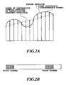
- Fig. 2A is a diagram illustrating the principle of the power measurement of the transmitted signal carried out by a receiving station in accordance with the present invention.
- the pilot signal is periodically inserted into the transmitted signal (see, Fig. 2B also).
- the interpolating coherent detection using the pilot signal obtains a line across the successive pilot signals as indicated by the broken line in Fig. 2A.
- received information symbols fluctuate as denoted by the real line owing to the effect of fading.
- the present invention tries to achieve more accurate measurement of received signal power by obtaining the differences (interference power) between the power of the information symbols obtained by the interpolating coherent detection and the power of the information symbols undergoing the fading.
- Fig. 3 shows a configuration of an embodiment of a received SIR measuring apparatus in accordance with the present invention.
- the reference numeral 22 designates an interpolating coherent detector
- 24 designates a received desired wave power calculating portion
- 26 designates an integrator.
- the reference numeral 21 designates a synchronization detector
- 25 designates a quasi-interference power calculating portion
- 27 designates an integrator
- 28 designates an SIR measuring portion.
- a baseband received signal 20 is input to the synchronization detector 21, which regenerates the clock timings of the symbols and the slot timings, that is, the repetition period of the pilot signal. These timings regenerated by the synchronization detector 21 determine the operation timings of the remaining circuitry.
- the interpolating coherent detector 22 samples the received signal 20 at the clock timings delivered from the synchronization detector 21, and stores the sampled data in its memory not shown in Fig. 3.
- the pilot signal in the received signal is extracted in accordance with the slot timings, and is used for estimating the transfer function of its propagation path. This operation is repeated at each of the slot timings, which enables the transfer function to be estimated at that instant.
- the interpolating coherent detector 22 carrying out the primary interpolation of the transfer functions obtained from the pilots at both ends of the information symbol section, calculates the transfer function corresponding to each information symbol, and compensates for the information symbols. Making decision of each compensated information symbol results in the information symbols 23 which have undergone the absolute phase coherent detection.
- the received desired wave power calculating portion 24 obtains the received desired wave power, that is, the square of the distance of each decided information symbol 23 from the point of origin on the complex signal space.
- the quasi-interference power calculating portion 25 obtains quasi-interference power on the complex signal space from the decided information symbols 23 and the received signal 20.
- the quasi-interference power can be obtained by computing the differences between the data symbols and the fading envelope at the same sampling timings.
- the integrators 26 and 27 integrate the received desired wave power and the quasi-interference power in each slot to obtain their averages.
- the SIR measuring portion 28 obtains the received SIR 29 by dividing the averaged received desired wave power integral by the averaged quasi-interference power integral.
- a simple system configuration can be implemented because the received SIR is obtained only from the baseband received signal.
- highly accurate transmission power control can be implemented using for computing the received SIR the quasi-interference power obtained as the square of the distance between the received signal and the information symbols decided on the complex signal space, which will be described below.
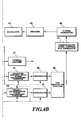
- Fig. 4 shows an embodiment of a transmission power control system using the received SIR measuring apparatus described above.
- the reference numeral 30 designates an antenna
- 31 designates a duplexer
- 32 designates a receiving radio frequency stage
- 33 designates a despreader
- 21 designates a synchronization detector
- 22 designates an interpolating coherent detector
- 24 designates a received desired wave power calculating portion
- 25 designates a quasi-interference power calculating portion
- 26 and 27 each designate an integrator
- 28 designates an SIR measuring portion
- 41 designates a transmission power control bit generator
- 42 designates a signal generator
- 43 designates an encoder
- 44 designates a modulator
- 45 designates a spreader
- 46 designates a transmitting radio frequency stage
- 47 designates a Viterbi decoder
- 48 designates a transmission power control bit extractor and 49 designates a transmission power controller.
- the blocks like those of Fig. 3 are denoted by the same reference nume
- a spread spectrum signal transmitted from a base station is received by the antenna 30.
- the received signal is input to the receiving radio frequency stage 32 through the duplexer 31.
- the receiving radio frequency stage 32 passes the received signal through a bandpass filter (BPF) to remove the components outside the passband, amplifies it, and carries out the frequency conversion to an intermediate frequency band (IF band) using the clock signal generated by a local oscillator.
- BPF bandpass filter
- IF band intermediate frequency band
- the received signal which has been frequency converted to the IF band is passed through a BPF, corrected to an appropriate level by an automatic-gain controller (AGC), and quasi-coherent detected, thereby frequency converted into a baseband.
- AGC automatic-gain controller
- the received signal thus frequency converted to the baseband is passed through the lowpass filter (LPF), undergoes analog-to-digital conversion (A/D conversion), and output as a digital signal.
- the digital received signal output from the receiving radio frequency stage 32 is despread by the despreader 33, and output as a narrow-band modulated signal.
- the signal output from the despreader 33 is demodulated by the interpolating coherent detector 22.
- the information signal in the demodulated signal is decoded by the Viterbi decoder, and is output.
- the transmission power control bits are extracted by the transmission power control bit extractor 48, and are fed to the transmission power controller 49.
- the transmission power controller 49 determines the transmission power in accordance with the transmission power control bits, and outputs the resultant control information to the transmitting radio frequency stage 46.
- the received SIR is obtained from the received signal despread by the despreader 33 as described above in connection with Fig. 3.
- the transmission power control bit generator 41 compares the received SIR with a predetermined target SIR. If the received SIR is smaller than the target SIR, the control bits commanding an increase of the transmission power are generated, whereas if the received SIR is greater than the target SIR, the control bits commanding a decrease of the transmission power are generated, and the control bits are supplied to the signal generator 42.
- the signal generator 42 assembles the transmitted frame including the transmission power control bits fed from the transmission power control bit generator 41, and supplies it to the encoder 43.
- the encoded transmitted signal is modulated by the modulator 44, spread by the spreader 45, and is fed to the transmitting radio frequency stage 46.
- the transmitting radio frequency stage 46 carries out the frequency conversion of the transmitted signal to the IF band and then to the RF band, and transmits it at the transmission power corresponding to the control information output from the transmission power controller 49.
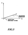
- Fig. 5 illustrates on the complex signal space the received desired wave power measurement.
- a transfer function 1 is obtained by primarily interpolating into the information symbol section the transfer functions obtained from the pilot signals. The transfer functions at respective information symbols are averaged within each slot.
- the received desired wave power 2 can be obtained by computing the square of the distance of the averaged transfer function.
- the received desired wave power measurement can be achieved by using at the receiving side the coherent detector for carrying out the coherent detection of the signal consisting of the information signal and the pilot signal with a known pattern inserted into the information signal at the predetermined period at the transmitting side.
- the coherent detector for carrying out the coherent detection of the signal consisting of the information signal and the pilot signal with a known pattern inserted into the information signal at the predetermined period at the transmitting side.
- it can be implemented by computing on the complex signal space of the baseband the power values of the fading envelope using the interpolation of the pilot signal, by averaging the power values in the sections at the predetermined pilot signal intervals, and by adopting the averaged value as the received desired wave power.
- Fig. 6 illustrates on the complex signal space another received desired wave power measuring method.
- Dividing the received data symbol 3 by the transfer function 1 gives a provisional information symbol 5 whose transfer function is compensated for.
- a weighted information symbol 6 is obtained by multiplying the provisional information symbol 5 by the square of the transfer function 1.
- the weighted information symbol 6 equals the product of the received data symbol 3 and the complex conjugate of the transfer function 1.
- the received desire wave power is obtained by compensating for the phase of the weighted information symbol 6 with the position of the signal point on the complex signal space, by averaging the compensated values in each slot, and by adopting the square of the distance of the average as the received desired wave power.
- the received desired wave power measurement can be achieved on the complex signal space by computing the ratio of the received data symbols to the fading envelope obtained by interpolating the pilot signals, by multiplying the ratio by the square of the fading envelope, by averaging the product in the section at the pilot signal interval, and by adopting the square of the absolute value of the average as the received desired wave power.
- Fig. 7 illustrates on the complex signal space a received interference wave power measurement.
- An estimated signal point 7 can be obtained by checking the quadrant on the complex signal space in which the weighted information symbol is present.
- the estimated signal point 7 is determined by the modulation scheme of the symbol, having a magnitude of unity and an angle of 45 degrees in each quadrant. Then, the received data symbol 3 is divided by the estimated signal point 7 to obtain a transfer function 9 including interference components.
- the transfer function 9 including the interference components can be obtained by rotating the received data symbol 3 about the axis of the unit circle.
- An interference wave 10 can be obtained as the difference between the transfer function 1 and the transfer function 9 including the interference components.
- the received interference wave power can be obtained by averaging the square of the distance of the received interference wave 10 in one slot.
- the received interference wave power measurement can be achieved on the complex signal space by computing the ratio of the received data symbols to the fading envelope obtained by the interpolation, by multiplying the ratio by the square of the fading envelope, by deciding the signal point from their product, by computing the fading envelope including the interference components using the received data symbols and the decision value, by computing the difference between the computed value and the fading envelope obtained by the interpolation, by integrating the square of the difference in the section at the pilot signal interval, by averaging the integrals over a plurality of sections at the pilot signal intervals, and by adopting the average as the received interference wave power.
- Fig. 8 illustrates on the complex signal space another received interference wave power measurement.
- the received interference wave 10 can be obtained as the difference between the transfer function 9 including the interference components and the average value 11 of the transfer functions 9.
- the received interference wave power can be obtained by integrating the square of the distance of the received interference wave 10 in each slot, and by averaging the integrals over a plurality of slots.
- the received interference wave power can be obtained by integrating the square of the distance of the received interference wave 10 in the pilot section, and by averaging the integrals over a plurality of slots.
- the received interference wave power measurement can be achieved on the complex signal space by computing the ratio of the received data symbols to the fading envelope obtained by the interpolation, by multiplying the ratio by the square of the fading envelope, by deciding the signal point from their product, by computing the fading envelope including the interference components using the received data symbols and the decision value, by computing the average of the received data symbols in the section at the pilot signal interval, by computing the difference between the computed average value and the fading envelope obtained by the interpolation, by integrating the square of the difference in the section at the pilot signal interval, by averaging the integrals over a plurality of sections at the pilot signal intervals, and by adopting the average as the received interference wave power.
- the received interference wave power measurement can be achieved on the complex signal space by computing the ratio of the received data symbols to the fading envelope obtained by the interpolation, by multiplying the ratio by the square of the fading envelope, by deciding the signal point from their product, by computing the fading envelope including the interference components using the received data symbols and the decision value, by computing the average of the received data symbols in the section at the pilot signal interval, by computing the difference between the computed average value and the fading envelope obtained by the interpolation, by integrating the square of the difference in the section only of the pilot signal, by averaging the integrals over a plurality of sections at the pilot signal intervals, and by adopting the average as the received interference wave power.
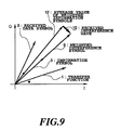
- Fig. 9 illustrates on the complex signal space still another received interference wave power measurement.
- An average value 12 of weighted information symbols can be obtained by compensating the weighted information symbols 6 for their phases with the positions of the signal point on the complex signal space, and by averaging the compensated values in each slot.
- the received interference wave 10 can be obtained as the difference between each weighted information symbol 6 and their average value 12.
- the received interference wave power measurement can be achieved on the complex signal space by computing the ratio of the received data symbols to the fading envelope obtained by the interpolation, by multiplying the ratio by the square of the fading envelope, by computing the average of the resultant product in the section at the pilot signal interval, by computing the difference between the computed average value and the resultant product, by integrating the square of the difference in the section at the pilot signal interval, by averaging the integrals over a plurality of sections at the pilot signal intervals, and by adopting the average as the received interference wave power.
- Fig. 10 is a block diagram for carrying out the received desired wave power measurement described above on the complex signal space in Fig. 5.
- the baseband received signal 123 is supplied to a pilot signal detector 124.
- a transfer function estimator 125 estimates the transfer function corresponding to the pilot signal using the pilot signal detected by the pilot signal detector 124.
- An interpolator 126 obtains the transfer functions corresponding to the information symbols by primarily interpolating the transfer functions obtained from the pilot signals located at both ends of the information symbol section.
- An averaging portion 127 averages in each slot the transfer functions obtained by the interpolator 126, and a power calculating portion 128 computes the power of the average value obtained by the averaging portion 127.
- the resultant power computed by the power calculating portion 128 is output as received desired wave power 129.
- Fig. 11 is a block diagram for implementing the received desired wave power measurement described above on the complex signal space in Fig. 6.
- the blocks like those of Fig. 10 are designated by the same reference numerals.
- the baseband received signal 123 is supplied to a pilot signal detector 131 and a weighting multiplier 134.
- the output of a transfer function estimator 132 is passed through a phase inverter 133 for taking its complex conjugate, and is input to the weighting multiplier 134.
- the multiplier 134 (weighting multiplier 134) multiplies the received signal 123 by the estimated function to obtain a signal from which the fading has been removed.
- the averaging portion 127 averages the output of the multiplier 134 in one slot, and the power calculating portion 128 computes the power of the average value obtained by the averaging portion 127.
- the resultant power computed by the power calculating portion 128 is output as the received desired wave power 129.
- Fig. 12 is a block diagram for implementing the received interference wave power measurement described on the complex signal space in Fig. 5.
- An output of a multiplier 139 corresponds to the output of the weighting multiplier 134 in Fig. 11, and an interpolation output 142 corresponds to the output from the interpolator 126 in Fig. 10.
- the baseband received signal 123 is input to a transfer function estimating divider 141, and the multiplier output 139 is input to a signal point decision portion 140.
- the signal point decision portion 140 decides the signal point of each information symbol by checking the quadrant in which the multiplier output 139 is present.
- the transfer function estimating divider 141 outputs the ratio of the baseband received signal 123 to the signal point.
- a difference detector 143 outputs a difference between the ratio and the interpolation output 142. After calculating the power of the difference in a power calculating portion 144, an averaging portion 145 averages the power in one slot, and outputs the average value as received interference wave power 146.
- Fig. 13 is a block diagram for implementing the received interference wave power measurement described above on the complex signal space in Fig. 7.
- the same reference numerals as those of the foregoing drawing designate like components.
- the baseband received signal 123 is input to the transfer function estimating divider 141.
- An averaging portion 151 computes the average value of the transfer function in each slot, or in each pilot section.
- the difference detector 143 outputs the differences between the average value and the output of the transfer function estimating divider 141.
- the power calculating portion 144 calculates and outputs the power of the differences.
- the averaging portion 145 averages the power in each slot, or in each pilot section. The average value is output as the received interference wave power 146.
- Fig. 14 is a block diagram for implementing the received interference wave power measurement described above on the complex signal space in Fig. 7.
- Fig. 14 the same block as those of the foregoing drawing are designated by the same reference numerals.
- the baseband received signal 123 is supplied to the pilot signal detector 131 and weighting multiplier 134.
- the output of the transfer function estimator 132 is passed through the phase inverter 133 for taking its complex conjugate, and is input to the weighting multiplier 134.
- the output of the multiplier 134 is input to the averaging portion 127 and a buffer 162.
- the buffer 162 is used for holding the multiplier outputs of one slot while averaging the multiplier outputs.
- a difference detector 163 computes the difference between the buffer output and the average value.
- the power calculating portion 128 computes the power of the output of the difference detector 163.
- the resultant power computed by the power calculating portion 128 is output as the received interference wave power 146.
- the blocks of the power measurement of Figs. 10-14 can be implemented using a DSP (Digital Signal Processor).
- DSP Digital Signal Processor
- Fig. 15 is a block diagram of the received SIR measuring apparatus.
- the received SIR measuring apparatus applies the configurations for measuring the received desired wave power and received interference wave power described above in connection with Figs. 10-12.
- the synchronization detector 21 generates a synchronizing signal from the baseband received signal 123, and supplies it to portions requiring it.
- the SIR computation divider 28 computes the ratio of the received desired wave power 129 to the received interference wave power 146, which is output as a received SIR 182.
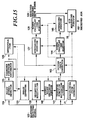
- Fig. 16 shows an embodiment of a transmission power control system applying the foregoing received SIR measurement.
- the reference numeral 30 designates an antenna
- 31 designates a duplexer
- 32 designates a receiving radio frequency stage
- 33 designates a despreader
- 22 designates an interpolating coherent detector
- 133 designates a phase inverter
- 134 designates a weighting multiplier
- 140 designates a signal point decision portion
- 141 designates a transfer function estimating divider
- 21 designates a synchronization detector
- 47 designates a Viterbi decoder
- 127 designates an averaging portion
- 163 designates a difference detector
- 144 designates a power calculating portion
- 145 designates an averaging portion
- 128 designates a power calculating portion
- 28 designates an SIR measuring portion
- 41 designates a transmission power control bit generator
- 42 designates a signal generator
- 43 designates an encoder
- 44 designates a modulator
- 45 designates a spreader
- 46 designates a transmitting radio frequency stage
- 48 design
- the received SIR measurement is carried out as described above in connection with Fig. 13.
- the transmission power control bit generator 41 compares the measured received SIR with the predetermined target SIR, and sets the transmission power control bits such that the transmission power is decreased when the received SIR exceeds the target SIR, and the transmission power is increased when the received SIR is below the target SIR.
- the transmission power control bit extractor 48 extracts the transmission power control bits from the baseband signal after the interpolating coherent detection, and the transmission power controller 49 increases or decreases the transmission power in response to the transmission power control bits.
- Fig. 17 is a graph illustrating the error characteristics of the transmission power control when the present invention is applied, in which the horizontal axis represents the maximum Doppler fDTtpc normalized by the power control interval (slot), and the vertical axis represents the standard deviation of the differences between the received SIR and the target SIR.
- the transmission power control step is set at 1 dB
- the control delay is set at 2Ttpc.
- the solid line indicates characteristics when the received SIR was perfectly measured, and open circles plotted indicate characteristics when the present invention is applied.
- the graph shows that the present invention can achieve the characteristics which is little inferior to the ideal case.
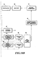
- Fig. 18 shows an embodiment of the transmission power control system for suspending the transmission power control by detecting the fast fading, in which like portions are designated by the same reference numerals as in the foregoing figure.
- the reference numeral 50 designates a fading envelope power variation amount detector
- 51 designates a fading envelope power variation amount comparator.
- the fading envelope power variation amount detector 50 detects the power of the pilot symbols which are located at both ends of the frame and used for the interpolation, and obtains their difference.
- the difference represents the power variation amount of the fading envelope.
- the fading envelope power variation amount comparator 51 compares the difference with a predetermined allowable variation amount and in terms of the absolute value of the power variation amount. When the variation amount of the fading envelope exceeds the allowable amount, the fading envelope power variation amount comparator 51 commands the transmitting radio frequency stage 46 to stop the transmission power control by providing it with the information of suspending the transmission power control.
- the fading envelope power variation amount comparator 51 supplies the transmitting radio frequency stage 46 with the information to restart the transmission power control so that the transmission power control based on the control information fed from the transmission power controller 49 is restarted.
Description
- The present invention relates to a received SIR measuring method and apparatus, and a power transmission control system applied to a CDMA (Code Division Multiple Access) system employed in mobile communications.
- In the CDMA system, since the same frequency band is shared by multiple users, signals of other users become interference signals which degrade the communication quality of a particular user. When a base station communicates with near and remote mobile stations at the same time, it receives the transmitted signal from the near mobile station at a high level, whereas from the remote one at a much lower level. Thus, the communications between the base station and the remote mobile station presents a problem in that the channel quality is sharply degraded by interference from the near mobile station, which is generally called a near-far problem.
- As one of the techniques used for solving the near-far problem, transmission power control has been studied which controls the transmission power such that the received power of a receiving station, or the SIR (Signal-to-Interference plus noise power Ratio) thereof is kept fixed regardless of the location of a mobile station. This will provide consistent channel quality across a service area. In particular, for reverse link channels, the transmission power control of the mobile stations are carried out so that the received power or SIR is kept constant of the signals transmitted from the mobile stations and received at the receiving terminal of the base station.
- Since the CDMA scheme considers the interference from other users as white noise, an increasing number of users is equivalent to an increase of noise power. Thus, the capacity in terms of the number of simultaneous users in the same cell depends on the received SIR for achieving required channel quality. In contrast, concerning the forward link channels, since incoming signals from the intended user and other users causing the interference arrive through the same propagation path, their long term fluctuations, short term fluctuations and instantaneous fluctuations are the same, and hence the received SIR except for the noise power is always constant. This means that no transmission power control is necessary as long as the interference within the same cell is handled. However, since the CDMA scheme with its interference equivalent to white noise reuses the same frequency band in contiguous cells, the interference therefrom must be taken into account. Although the interference power from other cells has instantaneous fluctuations due to Rayleigh fading like the interference within the cell, the fluctuations differ from those of the desired signal.
- The CDMA system standardized by TIA in the United States does not basically perform the forward link transmission power control. Instead, a method is employed in which a mobile station detects a frame error rate, and requires the base station to increase the transmission power to the mobile station when the error rate exceeds a predetermined threshold value. This is because a sharp increase of the transmission power would increase the interference to other cells. However, since the signals transmitted from other cell base stations become instantaneously fluctuating interference signals, the conventional technique described above cannot follow them.
- As a transmission power control method to follow the instantaneous fluctuations, a closed loop transmission power control system is known which employs transmission power control bits. In this control system, when a mobile station within a cell communicates with the base station in that cell, it measures the received SIR of the desired wave from the base station, and determines the transmission power control bits for controlling the transmission power of the base station in accordance with the measurement results. Subsequently, the mobiles station inserts the transmission power control bits into its transmitted signal and transmits them to the base station. Receiving the signal transmitted from the mobile station, the base station extracts the transmission power control bits therefrom, and determines the transmission power in accordance with the command of the transmission power control bits. In addition, the base station measures the received SIR of the wave from the mobile station, and determines the transmission power control bits for controlling the transmission power of the mobile station on the basis of the measurement results. Then, the base station inserts the transmission power control bits into the transmitted signal, and transmits them to the mobile station. Receiving the signal transmitted from the base station, the mobile station extracts the transmission power control bits, and determines the transmission power in accordance with the instructions of the transmission power control bits. The closed loop thus formed between the mobile station and the base station enables the mobile station to control its transmission power. The close loop transmission power control using the transmission power control bits requires a highly accurate SIR measurement technique.
- EP 0682417 discloses a transmission power control method for use in a CDMA mobile communication system including a mobile station and a base station. The mobile station measures the received power and interference of the received signal of the spread spectrum signal transmitted from the base station and uses it to calculate the received SIR using the techniques acknowledged as prior art in the present application.
- Conventional SIR measurement techniques, however, have a problem in that the measurement accuracy of the received desired wave power can be degraded at the places where the envelope of the received signal falls owing to fading. This is because they perform the measurements using the received data symbols decided by the interpolation of pilot signals, and this can cause large differences between actual and interpolated values of the received data symbols at these places.
- In addition, using the entire interval between intermittent pilot signals as the integration interval of the fading envelope power can cause the degradation in the measurement accuracy of the received interference power because of the decision error of signal points of the received signal.
- Therefore, an object of the present invention is to provide a received SIR measuring method and apparatus which can improve the accuracy of the received SIR measurement.
- Another object of the present invention is to achieve the transmission power control by applying the measuring apparatus.
- According to a first aspect of the present invention, there is provided a received SIR, that is the signal-to-interference plus noise power ratio, measuring method of a communications system using a signal including a known pilot signal inserted into an information signal at predetermined intervals, said method being characterized by comprising:
- the step of measuring received desired wave power which includes the step of computing power values of a fading envelope obtained by interpolation and the step of averaging the power values in a section between successive pilot signals, and which adopts the obtained average value as the received desired wave power;
- the step of measuring received interference wave power which obtains received interference wave power from received data symbols and the fading envelope obtained by the interpolation; and
- the step of computing the ratio of the received desired wave power to the received interference wave power, wherein the computed ratio is adopted as the SIR.
- According to a second aspect of the present invention, there is provided a received SIR, that is the signal-to-interference plus noise power ratio, measuring method of a communications system using a signal including a known pilot signal inserted into an information signal at predetermined intervals, said method being characterized by comprising:
- the step of measuring received desired wave power including the steps of:
- computing ratios of received data symbols to a fading envelope obtained by interpolation;
- multiplying the ratios by a square of the fading envelope;
- averaging products of the multiplication in the section between successive pilot signals; and
- obtaining a square of an absolute value of an average value obtained by the averaging,
- the step of measuring received interference wave power which obtains received interference wave power from the received data symbols and the fading envelope obtained by the interpolation; and
- the step of computing the ratio of the received desired wave power to the received interference wave power,
- According to a third aspect of the present invention, there is provided a received SIR measuring apparatus of a communications system using a signal including a known pilot signal inserted into an information signal at predetermined intervals, said apparatus being characterized by comprising:
- a received desired wave power measuring circuit including:
- means for computing power values of a fading envelope obtained by interpolation; and
- means for averaging the power values in a section between successive pilot signals,
- a received interference wave power measuring circuit for measuring received interference wave power from received data symbols and the fading envelope; and
- a computing circuit for computing the ratio of the received desired wave power to the received interference wave power,
- According to a fourth aspect of the present invention, there is provided a received SIR measuring apparatus of a communications system using a signal including a known pilot signal inserted into an information signal at predetermined intervals, said apparatus being characterized by comprising:
- a received desired wave power measuring circuit including:
- means for computing ratios of received data symbols to a fading envelope obtained by interpolation;
- means for multiplying the ratios by a square of the fading envelope; and
- means for averaging products of the multiplication in the section between successive pilot signals,
- a received interference wave power measuring circuit for measuring received interference wave power from the received data symbols and the fading envelope; and
- a computing circuit for computing the ratio of the received desired wave power to the received interference wave power,
- According to a fifth aspect of the present invention, there is provided a transmission power control system comprising:
- means for measuring received SIR according to the third or fourth aspect of the present invention, wherein the measured SIR is compared with a target SIR;
- means for transmitting a transmission power control signal to a party station in response to a compared result;
- means for receiving and demodulating a transmission power control signal transmitted from the party station; and
- means for controlling transmission power in accordance with the demodulated transmission power control signal.
-
- Fig. 1 is a diagram illustrating a frame structure used for the interpolating coherent detection;
- Fig. 2A is a diagram illustrating relationships between a fading envelope and the interpolating coherent detection;
- Fig. 2B is a diagram illustrating a transmitted signal into which a pilot signal is inserted;
- Fig. 3 is a block diagram showing a configuration of a received SIR measuring apparatus;
- Fig. 4 is a block diagram showing an embodiment of a transmission power control system;
- Fig. 5 is a diagram illustrating a received desired wave power measurement described on a complex signal space;
- Fig. 6 is a diagram illustrating another received desired wave power measurement described on a complex signal space;
- Fig. 7 is a diagram illustrating a received interference wave power measurement described on a complex signal space;
- Fig. 8 is a diagram illustrating another received interference wave power measurement described on a complex signal space;
- Fig. 9 is a diagram illustrating still another received interference wave power measurement described on a complex signal space;
- Fig. 10 is a block diagram for implementing a received desired wave power measurement;
- Fig. 11 is a block diagram for implementing another received desired wave power measurement;
- Fig. 12 is a block diagram for implementing a received interference wave power measurement;
- Fig. 13 is a block diagram for implementing another received interference wave power measurement;
- Fig. 14 is a block diagram for implementing still another received interference wave power measurement;
- Fig. 15 is a block diagram showing a received desired wave power measuring apparatus;
- Fig. 16 is a block diagram showing an embodiment of a transmission power control system;
- Fig. 17 is a graph illustrating transmission power control error characteristics of the transmission power control system; and
- Fig. 18 is a block diagram showing another embodiment of a transmission power control system.
- The following embodiments in accordance with the present invention relate to the received desired wave power measurement for measuring power of a received desired wave by the straightforward use of the measured values of the amplitude of received data symbols.
- Since both the transmitting and receiving stations know the pattern of the pilot signal used for the power measurement in advance, they can compute the fading envelope power including noise components without causing signal point decision errors. Accordingly, the received desired wave power measurement which will be described below carries out the power measurement of a received interference wave by integrating in the pilot signal section the difference between the average value of the transmitted data symbols and the fading envelope including the noise components, and by averaging the integrated values over a plurality of slots, thereby adopting the averages of the integrated values as the received interference power.
- The embodiments in accordance with the present invention will now be described in detail with reference to the drawings.
- Fig. 1 illustrates an example of a signal structure for implementing the coherent detection using the pilot signal. The pilot signal whose phase is known in advance to both transmitting and receiving sides is periodically inserted into a transmitted signal. One period between successive pilot signals is called a slot.
- Fig. 2A is a diagram illustrating the principle of the power measurement of the transmitted signal carried out by a receiving station in accordance with the present invention. As shown in Fig. 1, the pilot signal is periodically inserted into the transmitted signal (see, Fig. 2B also). The interpolating coherent detection using the pilot signal obtains a line across the successive pilot signals as indicated by the broken line in Fig. 2A. Actually received information symbols, however, fluctuate as denoted by the real line owing to the effect of fading. The present invention tries to achieve more accurate measurement of received signal power by obtaining the differences (interference power) between the power of the information symbols obtained by the interpolating coherent detection and the power of the information symbols undergoing the fading.
- Fig. 3 shows a configuration of an embodiment of a received SIR measuring apparatus in accordance with the present invention. In this figure, the
reference numeral 22 designates an interpolating coherent detector, 24 designates a received desired wave power calculating portion, and 26 designates an integrator. Thereference numeral 21 designates a synchronization detector, 25 designates a quasi-interference power calculating portion, 27 designates an integrator, and 28 designates an SIR measuring portion. - With such a circuit configuration, a baseband received
signal 20 is input to thesynchronization detector 21, which regenerates the clock timings of the symbols and the slot timings, that is, the repetition period of the pilot signal. These timings regenerated by thesynchronization detector 21 determine the operation timings of the remaining circuitry. The interpolatingcoherent detector 22 samples the receivedsignal 20 at the clock timings delivered from thesynchronization detector 21, and stores the sampled data in its memory not shown in Fig. 3. The pilot signal in the received signal is extracted in accordance with the slot timings, and is used for estimating the transfer function of its propagation path. This operation is repeated at each of the slot timings, which enables the transfer function to be estimated at that instant. The interpolatingcoherent detector 22, carrying out the primary interpolation of the transfer functions obtained from the pilots at both ends of the information symbol section, calculates the transfer function corresponding to each information symbol, and compensates for the information symbols. Making decision of each compensated information symbol results in theinformation symbols 23 which have undergone the absolute phase coherent detection. - The received desired wave
power calculating portion 24 obtains the received desired wave power, that is, the square of the distance of each decidedinformation symbol 23 from the point of origin on the complex signal space. On the other hand, the quasi-interferencepower calculating portion 25 obtains quasi-interference power on the complex signal space from the decidedinformation symbols 23 and the receivedsignal 20. The quasi-interference power can be obtained by computing the differences between the data symbols and the fading envelope at the same sampling timings. - The
integrators SIR measuring portion 28 obtains the receivedSIR 29 by dividing the averaged received desired wave power integral by the averaged quasi-interference power integral. - According to the present invention, a simple system configuration can be implemented because the received SIR is obtained only from the baseband received signal. In addition, highly accurate transmission power control can be implemented using for computing the received SIR the quasi-interference power obtained as the square of the distance between the received signal and the information symbols decided on the complex signal space, which will be described below.
- Fig. 4 shows an embodiment of a transmission power control system using the received SIR measuring apparatus described above. In Fig. 4, the
reference numeral 30 designates an antenna, 31 designates a duplexer, 32 designates a receiving radio frequency stage, 33 designates a despreader, 21 designates a synchronization detector, 22 designates an interpolating coherent detector, 24 designates a received desired wave power calculating portion, 25 designates a quasi-interference power calculating portion, 26 and 27 each designate an integrator, 28 designates an SIR measuring portion, 41 designates a transmission power control bit generator, 42 designates a signal generator, 43 designates an encoder, 44 designates a modulator, 45 designates a spreader, 46 designates a transmitting radio frequency stage, 47 designates a Viterbi decoder, 48 designates a transmission power control bit extractor and 49 designates a transmission power controller. The blocks like those of Fig. 3 are denoted by the same reference numerals. - The operation will now be described when the transmitter with the configuration is applied to a mobile station.
- A spread spectrum signal transmitted from a base station is received by the
antenna 30. The received signal is input to the receivingradio frequency stage 32 through theduplexer 31. The receivingradio frequency stage 32 passes the received signal through a bandpass filter (BPF) to remove the components outside the passband, amplifies it, and carries out the frequency conversion to an intermediate frequency band (IF band) using the clock signal generated by a local oscillator. The received signal which has been frequency converted to the IF band is passed through a BPF, corrected to an appropriate level by an automatic-gain controller (AGC), and quasi-coherent detected, thereby frequency converted into a baseband. The received signal thus frequency converted to the baseband is passed through the lowpass filter (LPF), undergoes analog-to-digital conversion (A/D conversion), and output as a digital signal. The digital received signal output from the receivingradio frequency stage 32 is despread by thedespreader 33, and output as a narrow-band modulated signal. The signal output from thedespreader 33 is demodulated by the interpolatingcoherent detector 22. The information signal in the demodulated signal is decoded by the Viterbi decoder, and is output. The transmission power control bits are extracted by the transmission powercontrol bit extractor 48, and are fed to thetransmission power controller 49. Thetransmission power controller 49 determines the transmission power in accordance with the transmission power control bits, and outputs the resultant control information to the transmittingradio frequency stage 46. On the other hand, the received SIR is obtained from the received signal despread by thedespreader 33 as described above in connection with Fig. 3. - The transmission power
control bit generator 41 compares the received SIR with a predetermined target SIR. If the received SIR is smaller than the target SIR, the control bits commanding an increase of the transmission power are generated, whereas if the received SIR is greater than the target SIR, the control bits commanding a decrease of the transmission power are generated, and the control bits are supplied to thesignal generator 42. Thesignal generator 42 assembles the transmitted frame including the transmission power control bits fed from the transmission powercontrol bit generator 41, and supplies it to theencoder 43. The encoded transmitted signal is modulated by themodulator 44, spread by thespreader 45, and is fed to the transmittingradio frequency stage 46. The transmittingradio frequency stage 46 carries out the frequency conversion of the transmitted signal to the IF band and then to the RF band, and transmits it at the transmission power corresponding to the control information output from thetransmission power controller 49. - The power calculation of the received desired wave and received interference wave will now be described in detail using the complex signal space.
- The power measurement of the received desired wave will be described with reference to Figs. 5 and 6.
- Fig. 5 illustrates on the complex signal space the received desired wave power measurement. A
transfer function 1 is obtained by primarily interpolating into the information symbol section the transfer functions obtained from the pilot signals. The transfer functions at respective information symbols are averaged within each slot. The received desiredwave power 2 can be obtained by computing the square of the distance of the averaged transfer function. - Thus, the received desired wave power measurement can be achieved by using at the receiving side the coherent detector for carrying out the coherent detection of the signal consisting of the information signal and the pilot signal with a known pattern inserted into the information signal at the predetermined period at the transmitting side. Specifically, it can be implemented by computing on the complex signal space of the baseband the power values of the fading envelope using the interpolation of the pilot signal, by averaging the power values in the sections at the predetermined pilot signal intervals, and by adopting the averaged value as the received desired wave power.
- Fig. 6 illustrates on the complex signal space another received desired wave power measuring method. Dividing the received
data symbol 3 by thetransfer function 1 gives aprovisional information symbol 5 whose transfer function is compensated for. Then, aweighted information symbol 6 is obtained by multiplying theprovisional information symbol 5 by the square of thetransfer function 1. Theweighted information symbol 6 equals the product of the receiveddata symbol 3 and the complex conjugate of thetransfer function 1. The received desire wave power is obtained by compensating for the phase of theweighted information symbol 6 with the position of the signal point on the complex signal space, by averaging the compensated values in each slot, and by adopting the square of the distance of the average as the received desired wave power. - Thus, the received desired wave power measurement can be achieved on the complex signal space by computing the ratio of the received data symbols to the fading envelope obtained by interpolating the pilot signals, by multiplying the ratio by the square of the fading envelope, by averaging the product in the section at the pilot signal interval, and by adopting the square of the absolute value of the average as the received desired wave power.
- Next, the power measurement of the received interference wave will be described with reference to Figs, 7-9.
- Fig. 7 illustrates on the complex signal space a received interference wave power measurement. An estimated
signal point 7 can be obtained by checking the quadrant on the complex signal space in which the weighted information symbol is present. The estimatedsignal point 7 is determined by the modulation scheme of the symbol, having a magnitude of unity and an angle of 45 degrees in each quadrant. Then, the receiveddata symbol 3 is divided by the estimatedsignal point 7 to obtain atransfer function 9 including interference components. - Since the estimated
signal point 7 is located on the circumference of a unit circle, thetransfer function 9 including the interference components can be obtained by rotating the receiveddata symbol 3 about the axis of the unit circle. Aninterference wave 10 can be obtained as the difference between thetransfer function 1 and thetransfer function 9 including the interference components. The received interference wave power can be obtained by averaging the square of the distance of the receivedinterference wave 10 in one slot. - Thus, the received interference wave power measurement can be achieved on the complex signal space by computing the ratio of the received data symbols to the fading envelope obtained by the interpolation, by multiplying the ratio by the square of the fading envelope, by deciding the signal point from their product, by computing the fading envelope including the interference components using the received data symbols and the decision value, by computing the difference between the computed value and the fading envelope obtained by the interpolation, by integrating the square of the difference in the section at the pilot signal interval, by averaging the integrals over a plurality of sections at the pilot signal intervals, and by adopting the average as the received interference wave power.
- Fig. 8 illustrates on the complex signal space another received interference wave power measurement. The received
interference wave 10 can be obtained as the difference between thetransfer function 9 including the interference components and the average value 11 of the transfer functions 9. - The received interference wave power can be obtained by integrating the square of the distance of the received
interference wave 10 in each slot, and by averaging the integrals over a plurality of slots. Alternatively, the received interference wave power can be obtained by integrating the square of the distance of the receivedinterference wave 10 in the pilot section, and by averaging the integrals over a plurality of slots. - Thus, the received interference wave power measurement can be achieved on the complex signal space by computing the ratio of the received data symbols to the fading envelope obtained by the interpolation, by multiplying the ratio by the square of the fading envelope, by deciding the signal point from their product, by computing the fading envelope including the interference components using the received data symbols and the decision value, by computing the average of the received data symbols in the section at the pilot signal interval, by computing the difference between the computed average value and the fading envelope obtained by the interpolation, by integrating the square of the difference in the section at the pilot signal interval, by averaging the integrals over a plurality of sections at the pilot signal intervals, and by adopting the average as the received interference wave power.
- Likewise, the received interference wave power measurement can be achieved on the complex signal space by computing the ratio of the received data symbols to the fading envelope obtained by the interpolation, by multiplying the ratio by the square of the fading envelope, by deciding the signal point from their product, by computing the fading envelope including the interference components using the received data symbols and the decision value, by computing the average of the received data symbols in the section at the pilot signal interval, by computing the difference between the computed average value and the fading envelope obtained by the interpolation, by integrating the square of the difference in the section only of the pilot signal, by averaging the integrals over a plurality of sections at the pilot signal intervals, and by adopting the average as the received interference wave power.
- Fig. 9 illustrates on the complex signal space still another received interference wave power measurement. An
average value 12 of weighted information symbols can be obtained by compensating theweighted information symbols 6 for their phases with the positions of the signal point on the complex signal space, and by averaging the compensated values in each slot. The receivedinterference wave 10 can be obtained as the difference between eachweighted information symbol 6 and theiraverage value 12. - Thus, the received interference wave power measurement can be achieved on the complex signal space by computing the ratio of the received data symbols to the fading envelope obtained by the interpolation, by multiplying the ratio by the square of the fading envelope, by computing the average of the resultant product in the section at the pilot signal interval, by computing the difference between the computed average value and the resultant product, by integrating the square of the difference in the section at the pilot signal interval, by averaging the integrals over a plurality of sections at the pilot signal intervals, and by adopting the average as the received interference wave power.
- Next, referring to Figs. 10-14, concrete configurations will be described for implementing the power measurements of the received desired wave and the received interference wave described above on the complex signal space.
- Fig. 10 is a block diagram for carrying out the received desired wave power measurement described above on the complex signal space in Fig. 5.
- The baseband received
signal 123 is supplied to apilot signal detector 124. Atransfer function estimator 125 estimates the transfer function corresponding to the pilot signal using the pilot signal detected by thepilot signal detector 124. Aninterpolator 126 obtains the transfer functions corresponding to the information symbols by primarily interpolating the transfer functions obtained from the pilot signals located at both ends of the information symbol section. An averagingportion 127 averages in each slot the transfer functions obtained by theinterpolator 126, and apower calculating portion 128 computes the power of the average value obtained by the averagingportion 127. The resultant power computed by thepower calculating portion 128 is output as received desiredwave power 129. - Fig. 11 is a block diagram for implementing the received desired wave power measurement described above on the complex signal space in Fig. 6. In Fig. 11, the blocks like those of Fig. 10 are designated by the same reference numerals.
- The baseband received
signal 123 is supplied to apilot signal detector 131 and aweighting multiplier 134. The output of atransfer function estimator 132 is passed through aphase inverter 133 for taking its complex conjugate, and is input to theweighting multiplier 134. The multiplier 134 (weighting multiplier 134) multiplies the receivedsignal 123 by the estimated function to obtain a signal from which the fading has been removed. The averagingportion 127 averages the output of themultiplier 134 in one slot, and thepower calculating portion 128 computes the power of the average value obtained by the averagingportion 127. The resultant power computed by thepower calculating portion 128 is output as the received desiredwave power 129. - Fig. 12 is a block diagram for implementing the received interference wave power measurement described on the complex signal space in Fig. 5.
- An output of a
multiplier 139 corresponds to the output of theweighting multiplier 134 in Fig. 11, and aninterpolation output 142 corresponds to the output from theinterpolator 126 in Fig. 10. - The baseband received
signal 123 is input to a transferfunction estimating divider 141, and themultiplier output 139 is input to a signalpoint decision portion 140. The signalpoint decision portion 140 decides the signal point of each information symbol by checking the quadrant in which themultiplier output 139 is present. The transferfunction estimating divider 141 outputs the ratio of the baseband receivedsignal 123 to the signal point. Adifference detector 143 outputs a difference between the ratio and theinterpolation output 142. After calculating the power of the difference in apower calculating portion 144, an averagingportion 145 averages the power in one slot, and outputs the average value as receivedinterference wave power 146. - Fig. 13 is a block diagram for implementing the received interference wave power measurement described above on the complex signal space in Fig. 7. The same reference numerals as those of the foregoing drawing designate like components.
- The baseband received
signal 123 is input to the transferfunction estimating divider 141. An averagingportion 151 computes the average value of the transfer function in each slot, or in each pilot section. - The
difference detector 143 outputs the differences between the average value and the output of the transferfunction estimating divider 141. Thepower calculating portion 144 calculates and outputs the power of the differences. The averagingportion 145 averages the power in each slot, or in each pilot section. The average value is output as the receivedinterference wave power 146. - Fig. 14 is a block diagram for implementing the received interference wave power measurement described above on the complex signal space in Fig. 7. In Fig. 14, the same block as those of the foregoing drawing are designated by the same reference numerals.
- The baseband received
signal 123 is supplied to thepilot signal detector 131 andweighting multiplier 134. The output of thetransfer function estimator 132 is passed through thephase inverter 133 for taking its complex conjugate, and is input to theweighting multiplier 134. The output of themultiplier 134 is input to the averagingportion 127 and abuffer 162. Thebuffer 162 is used for holding the multiplier outputs of one slot while averaging the multiplier outputs. After the averagingportion 127 averages the outputs of the multiplier in one slot, adifference detector 163 computes the difference between the buffer output and the average value. Then, thepower calculating portion 128 computes the power of the output of thedifference detector 163. The resultant power computed by thepower calculating portion 128 is output as the receivedinterference wave power 146. - The blocks of the power measurement of Figs. 10-14 can be implemented using a DSP (Digital Signal Processor).
- Fig. 15 is a block diagram of the received SIR measuring apparatus.
- The received SIR measuring apparatus applies the configurations for measuring the received desired wave power and received interference wave power described above in connection with Figs. 10-12.
- The
synchronization detector 21 generates a synchronizing signal from the baseband receivedsignal 123, and supplies it to portions requiring it. TheSIR computation divider 28 computes the ratio of the received desiredwave power 129 to the receivedinterference wave power 146, which is output as a receivedSIR 182. - It is obvious that various configurations can be implemented to obtain the received SIR by combining the configurations for measuring the received desired wave power and the received interference wave power as shown in Figs. 10-14.
- Fig. 16 shows an embodiment of a transmission power control system applying the foregoing received SIR measurement.
- In Fig. 16, the
reference numeral 30 designates an antenna, 31 designates a duplexer, 32 designates a receiving radio frequency stage, 33 designates a despreader, 22 designates an interpolating coherent detector, 133 designates a phase inverter, 134 designates a weighting multiplier, 140 designates a signal point decision portion, 141 designates a transfer function estimating divider, 21 designates a synchronization detector, 47 designates a Viterbi decoder, 127 designates an averaging portion, 163 designates a difference detector, 144 designates a power calculating portion, 145 designates an averaging portion, 128 designates a power calculating portion, 28 designates an SIR measuring portion, 41 designates a transmission power control bit generator, 42 designates a signal generator, 43 designates an encoder, 44 designates a modulator, 45 designates a spreader, 46 designates a transmitting radio frequency stage, 48 designates a transmission power control bit extractor and 49 designates a transmission power controller. In Fig. 16, the interpolatingcoherent detector 22 corresponds to thepilot signal detector 124,transfer function estimator 125 andinterpolator 126 in Fig. 15. - The received SIR measurement is carried out as described above in connection with Fig. 13.
- The transmission power
control bit generator 41 compares the measured received SIR with the predetermined target SIR, and sets the transmission power control bits such that the transmission power is decreased when the received SIR exceeds the target SIR, and the transmission power is increased when the received SIR is below the target SIR. - In the receiving station, on the other hand, the transmission power
control bit extractor 48 extracts the transmission power control bits from the baseband signal after the interpolating coherent detection, and thetransmission power controller 49 increases or decreases the transmission power in response to the transmission power control bits. - Fig. 17 is a graph illustrating the error characteristics of the transmission power control when the present invention is applied, in which the horizontal axis represents the maximum Doppler fDTtpc normalized by the power control interval (slot), and the vertical axis represents the standard deviation of the differences between the received SIR and the target SIR. Here, the transmission power control step is set at 1 dB, and the control delay is set at 2Ttpc. The solid line indicates characteristics when the received SIR was perfectly measured, and open circles plotted indicate characteristics when the present invention is applied. The graph shows that the present invention can achieve the characteristics which is little inferior to the ideal case.
- Furthermore, it is apparent from the graph that the control error is nearly saturated when the fDTtpc is large. This is because the transmission power control cannot follow the instantaneous fluctuations as the fading rate increases. Accordingly, it is possible to save the power of the system by detecting the rate of the fading, and suspending the transmission power control during the fast fading.
- Fig. 18 shows an embodiment of the transmission power control system for suspending the transmission power control by detecting the fast fading, in which like portions are designated by the same reference numerals as in the foregoing figure. In Fig. 18, the
reference numeral 50 designates a fading envelope power variation amount detector, and 51 designates a fading envelope power variation amount comparator. - In Fig. 18, the fading envelope power
variation amount detector 50 detects the power of the pilot symbols which are located at both ends of the frame and used for the interpolation, and obtains their difference. The difference represents the power variation amount of the fading envelope. The fading envelope powervariation amount comparator 51 compares the difference with a predetermined allowable variation amount and in terms of the absolute value of the power variation amount. When the variation amount of the fading envelope exceeds the allowable amount, the fading envelope powervariation amount comparator 51 commands the transmittingradio frequency stage 46 to stop the transmission power control by providing it with the information of suspending the transmission power control. If the variation amount of the fading envelope returns to less than the allowable amount, the fading envelope powervariation amount comparator 51 supplies the transmittingradio frequency stage 46 with the information to restart the transmission power control so that the transmission power control based on the control information fed from thetransmission power controller 49 is restarted. - By thus suspending the transmission power control, the power saving of the entire system can be achieved.
Claims (22)
- A received SIR, that is the signal-to-interference plus noise power ratio, measuring method of a communications system using a signal including a known pilot signal inserted into an information signal at predetermined intervals, said method being characterized by comprising:the step of measuring received desired wave power which includes the step of computing power values of a fading envelope obtained by interpolation and the step of averaging the power values in a section between successive pilot signals, and which adopts the obtained average value as the received desired wave power;the step of measuring received interference wave power which obtains received interference wave power from received data symbols and the fading envelope obtained by the interpolation; andthe step of computing the ratio of the received desired wave power to the received interference wave power, wherein the computed ratio is adopted as the SIR.
- The received SIR measuring method as claimed in claim 1, wherein said step of measuring the received interference wave power comprises the steps of:computing ratios of the received data symbols to a fading envelope obtained by interpolation;multiplying the ratios by a square of the fading envelope, and making a decision of signal points from results of the multiplication;computing a fading envelope including interference components using the received data symbols and the decision values;computing differences between the computed value and the fading envelope obtained by the interpolation;integrating squares of the differences in the section between the successive pilot signals; andaveraging integrals obtained by the integration in the section between the successive pilot signals.
- The received SIR measuring method as claimed in claim 1, wherein said step of measuring the received interference wave power comprises the steps of:computing ratios of the received data symbols to a fading envelope obtained by interpolation;multiplying the ratios by a square of the fading envelope;making a decision of signal points from results of the multiplication;computing a fading envelope including interference components using the received data symbols and the decision results;computing differences between the computed value and the fading envelope obtained by the interpolation;integrating squares of the differences in the section between the successive pilot signals; andaveraging integrals obtained by the integration in a plurality of sections between the successive pilot signals.
- The received SIR measuring method as claimed in claim 1, wherein said step of measuring the received interference wave power comprises the steps of:computing ratios of the received data symbols to a fading envelope obtained by interpolation;multiplying the ratios by a square of the fading envelope;making a decision of signal points from results of the multiplication;computing a fading envelope including interference components using the received data symbols and the decision results;computing an average value of the received data symbols in a pilot signal section;computing differences between said fading envelope and said average value;integrating squares of the differences in the section between the successive pilot signals; andaveraging integrals obtained by the integration over a plurality of sections between the successive pilot signals.
- The received SIR measuring method as claimed in claim 1, wherein said step of measuring the received interference wave power comprises the steps of:computing ratios of the received data symbols to a fading envelope obtained by interpolation;multiplying the ratios by a square of the fading envelope;making a decision of signal points from results of the multiplication;computing a fading envelope including interference components using the received data symbols and the decision results;computing an average value of the received data symbols in a pilot signal section;computing differences between said fading envelope and said average value;integrating squares of the differences in only the pilot signal section; andaveraging integrals obtained by the integration over a plurality of sections between the successive pilot signals.
- The received SIR measuring method as claimed in claim 1, wherein said step of measuring the received interference wave power comprises the steps of:computing ratios of the received data symbols to a fading envelope obtained by interpolation;multiplying the ratios by a square of the fading envelope;averaging products of the multiplication in the section between successive pilot signals;computing differences between an average value obtained by the averaging and said products of the multiplication;integrating squares of the differences in the section between the successive pilot signals; andaveraging integrals obtained by the integration over a plurality of sections between the successive pilot signals.
- A received SIR, that is the signal-to-interference plus noise power ratio, measuring method of a communications system using a signal including a known pilot signal inserted into an information signal at predetermined intervals, said method being characterized by comprising:the step of measuring received desired wave power including the steps of:computing ratios of received data symbols to a fading envelope obtained by interpolation;multiplying the ratios by a square of the fading envelope;averaging products of the multiplication in the section between successive pilot signals; andobtaining a square of an absolute value of an average value obtained by the averaging,wherein the square of the absolute value is adopted as the received desired wave power;the step of measuring received interference wave power which obtains received interference wave power from the received data symbols and the fading envelope obtained by the interpolation; andthe step of computing the ratio of the received desired wave power to the received interference wave power,wherein the computed ratio is adopted as the SIR.
- The received SIR measuring method as claimed in claim 7, wherein said step of measuring the received interference wave power comprises the steps of:making a decision of signal points from results of the multiplication;computing a fading envelope including interference components using the received data symbols and the decision results;computing differences between the computed value and the fading envelope obtained by the interpolation;integrating squares of the differences in the section between the successive pilot signals; andaveraging integrals obtained by the integration in a plurality of sections between the successive pilot signals.
- The received SIR measuring method as claimed in claim 7, wherein said step of measuring the received interference wave power comprises the steps of;making a decision of signal points from results of the multiplication;computing a fading envelope including interference components using the received data symbols and the decision values;computing an average value of the received data symbols in the section between successive pilot signals;computing differences between said fading envelope and said average value;integrating squares of the differences in the section between the successive pilot signals; andaveraging integrals obtained by the integration over a plurality of sections between the successive pilot signals.
- The received SIR measuring method as claimed in claim 7, wherein said step of measuring the received interference wave power comprises the steps of:making a decision of signal points from results of the multiplication;computing a fading envelope including interference components using the received data symbols and the decision results;computing an average value of the received data symbols in a pilot signal section;computing differences between said fading envelope and said average value;integrating squares of the differences in only the pilot signal section; andaveraging integrals obtained by the integration over a plurality of sections between the successive pilot signals.
- The received SIR measuring method as claimed in claim 7, wherein said step of measuring the received interference wave power comprises the steps of:averaging products of the multiplication in the section between successive pilot signals;computing differences between an average value obtained by the averaging and said products of the multiplication;integrating squares of the differences in the section between the successive pilot signals; andaveraging integrals obtained by the integration over a plurality of sections between the successive pilot signals.
- A received SIR measuring apparatus of a communications system using a signal including a known pilot signal inserted into an information signal at predetermined intervals, said apparatus being characterized by comprising:a received desired wave power measuring circuit including:means for computing power values of a fading envelope obtained by interpolation; andmeans for averaging (127) the power values in a section between successive pilot signals,wherein the obtained average value is adopted as the received desired wave power;a received interference wave power measuring circuit for measuring received interference wave power from received data symbols and the fading envelope; anda computing circuit for computing the ratio of the received desired wave power to the received interference wave power,wherein the computed ratio is adopted as the SIR.
- The received SIR measuring apparatus as claimed in claim 12, wherein said received interference wave power measuring circuit comprises:means for computing ratios of the received data symbols to a fading envelope obtained by interpolation;means for multiplying the ratios by a square of the fading envelope;means for making a decision of signal points from results of the multiplication;means for computing (141) a fading envelope including interference components using the received data symbols and the decision results;means for computing (143) differences between the computed value and the fading envelope obtained by the interpolation;means for integrating squares of the differences in the section between the successive pilot signals; andmeans for averaging (145) integrals obtained by the integration in the section between the successive pilot signals.
- The received SIR measuring apparatus as claimed in claim 12, wherein said received interference wave power measuring circuit comprises:means for computing ratios of the received data symbols to a fading envelope obtained by interpolation;multiplying means for multiplying the ratios by a square of the fading envelope;means for making a decision of signal points (140) from results of the multiplication;means for computing (141) a fading envelope including interference components using the received data symbols and the decision results;means for computing (151) an average value of the received data symbols in the section between successive pilot signals;means for computing (143) differences between said fading envelope and said average value;means for integrating squares of the differences in the section between the successive pilot signals; andmeans for averaging (145) integrals obtained by the integration over a plurality of sections between the successive pilot signals.
- The received SIR measuring apparatus as claimed in claim 12, wherein said received interference wave power measuring circuit comprises:means for computing on a complex signal space ratios of the received data symbols to a fading envelope obtained by interpolation;means for multiplying the ratios by a square of the fading envelope;means for making a decision of signal points (140) from results of the multiplication;means for computing (141) a fading envelope including interference components using the received data symbols and the decision values;means for computing (151) an average value of the received data symbols in a pilot signal section;means for computing (143) differences between said fading envelope and said average value;means for integrating squares of the differences in only the pilot signal section; andmeans for averaging (145) integrals obtained by the integration over a plurality of sections between the successive pilot signals.
- The received SIR measuring apparatus as claimed in claim 12, characterized in that said received interference wave power measuring circuit comprises:means for computing on a complex signal space ratios of the received data symbols to a fading envelope obtained by interpolation;means for multiplying the ratios by a square of the fading envelope;means for averaging products of the multiplication in the section between successive pilot signals;means for computing differences between an average value obtained by the averaging and said products of the multiplication;means for integrating squares of the differences in the section between the successive pilot signals; andmeans for averaging integrals obtained by the integration over a plurality of sections between the successive pilot signals.
- A received SIR measuring apparatus of a communications system using a signal including a known pilot signal inserted into an information signal at predetermined intervals, said apparatus being characterized by comprising:a received desired wave power measuring circuit including:means for computing ratios of received data symbols to a fading envelope obtained by interpolation;means for multiplying (134) the ratios by a square of the fading envelope; andmeans for averaging (127) products of the multiplication in the section between successive pilot signals,wherein a square of an absolute value of the average value is adopted as received desired wave power;a received interference wave power measuring circuit for measuring received interference wave power from the received data symbols and the fading envelope; anda computing circuit for computing the ratio of the received desired wave power to the received interference wave power,wherein the computed ratio is adopted as the SIR.
- The received SIR measuring apparatus as claimed in claim 17, wherein said received interference wave power measuring circuit comprises:means for making a decision of signal points (140) from results of the multiplication;means for computing (141) a fading envelope including interference components using the received data symbols and the decision values;means for computing (143) differences between the computed value and the fading envelope obtained by the interpolation;means for integrating squares of the differences in the section between the successive pilot signals; andmeans for averaging (145) integrals obtained by the integration in a plurality of sections between the successive pilot signals.
- The received SIR measuring apparatus as claimed in claim 17, wherein said received interference wave power measuring circuit comprises:means for making a decision of signal points (140) from results of the multiplication;means for computing (141) a fading envelope including interference components using the received data symbols and the decision values;means for computing (151) an average value of the received data symbols in the section between successive pilot signals;means for computing (143) differences between said fading envelope and said average value;means for integrating squares of the differences in the section between the successive pilot signals; andmeans for averaging (145) integrals obtained by the integration over a plurality of sections between the successive pilot signals.
- The received SIR measuring apparatus as claimed in claim 17, wherein said received interference wave power measuring circuit comprises:means for making a decision of signal points from results of the multiplication;means for computing (141) a fading envelope including interference components using the received data symbols and the decision values;means for computing (151) an average value of the received data symbols in a pilot signal section;means for computing (143) differences between said fading envelope and said average value;means for integrating squares of the differences in only the pilot signal section; andmeans for averaging (145) integrals obtained by the integration over a plurality of sections between the successive pilot signals.
- The received SIR measuring apparatus as claimed in claim 17, wherein said received interference wave power measuring circuit comprises:means for averaging (127) products of the multiplication in the section between successive pilot signals;means for computing (163) differences between an average value obtained by the averaging and said products of the multiplication;means for integrating square of the differences in the section between the successive pilot signals; andmeans for averaging integrals obtained by the integration over a plurality of sections between the successive pilot signals.
- A transmission power control system comprising:means for measuring received SIR as defined in any one of claims 12-21, wherein the measured SIR is compared with a target SIR;means for transmitting a transmission power control signal to a party station in response to a compared result;means for receiving and demodulating a transmission power control signal transmitted from the party station; andmeans for controlling transmission power in accordance with the demodulated transmission power control signal.
Priority Applications (1)
| Application Number | Priority Date | Filing Date | Title |
|---|---|---|---|
| EP06076359A EP1708396A3 (en) | 1996-04-12 | 1997-04-14 | Method and instrument for measuring SIR and transmission power control |
Applications Claiming Priority (5)
| Application Number | Priority Date | Filing Date | Title |
|---|---|---|---|
| JP09157996A JP3358782B2 (en) | 1996-04-12 | 1996-04-12 | Received SIR measurement device and transmission power control device |
| JP91579/96 | 1996-04-12 | ||
| JP16297296A JP3417521B2 (en) | 1996-06-24 | 1996-06-24 | Received SIR measurement method, apparatus and transmission power control apparatus |
| JP162972/96 | 1996-06-24 | ||
| PCT/JP1997/001289 WO1997039545A1 (en) | 1996-04-12 | 1997-04-14 | Method and instrument for measuring receiving sir and transmission power controller |
Related Child Applications (1)
| Application Number | Title | Priority Date | Filing Date |
|---|---|---|---|
| EP06076359A Division EP1708396A3 (en) | 1996-04-12 | 1997-04-14 | Method and instrument for measuring SIR and transmission power control |
Publications (3)
| Publication Number | Publication Date |
|---|---|
| EP0833472A1 EP0833472A1 (en) | 1998-04-01 |
| EP0833472A4 EP0833472A4 (en) | 2004-04-21 |
| EP0833472B1 true EP0833472B1 (en) | 2006-09-20 |
Family
ID=26433023
Family Applications (2)
| Application Number | Title | Priority Date | Filing Date |
|---|---|---|---|
| EP06076359A Withdrawn EP1708396A3 (en) | 1996-04-12 | 1997-04-14 | Method and instrument for measuring SIR and transmission power control |
| EP97915720A Expired - Lifetime EP0833472B1 (en) | 1996-04-12 | 1997-04-14 | Method and instrument for measuring receiving sir and transmission power controller |
Family Applications Before (1)
| Application Number | Title | Priority Date | Filing Date |
|---|---|---|---|
| EP06076359A Withdrawn EP1708396A3 (en) | 1996-04-12 | 1997-04-14 | Method and instrument for measuring SIR and transmission power control |
Country Status (7)
| Country | Link |
|---|---|
| US (1) | US6034952A (en) |
| EP (2) | EP1708396A3 (en) |
| KR (1) | KR100321865B1 (en) |
| CN (1) | CN1111986C (en) |
| CA (1) | CA2224271C (en) |
| DE (1) | DE69736695T8 (en) |
| WO (1) | WO1997039545A1 (en) |
Families Citing this family (105)
| Publication number | Priority date | Publication date | Assignee | Title |
|---|---|---|---|---|
| JP3655057B2 (en) * | 1997-07-19 | 2005-06-02 | 松下電器産業株式会社 | CDMA transmitter and CDMA transmission method |
| JP3156652B2 (en) * | 1997-09-02 | 2001-04-16 | 日本電気株式会社 | Mobile wireless communication device |
| US6301237B1 (en) * | 1997-12-30 | 2001-10-09 | Matsushita Electric Industrial Co., Ltd. | CDMA radio multiplex transmitting device and a CDMA radio multiplex receiving device |
| JP3397677B2 (en) * | 1998-02-10 | 2003-04-21 | 松下電器産業株式会社 | Transmission power control device and wireless communication device |
| JP3363771B2 (en) * | 1998-02-23 | 2003-01-08 | 沖電気工業株式会社 | Method and apparatus for measuring radio wave characteristics |
| CA2230589C (en) * | 1998-02-25 | 2004-02-10 | Wen Tong | Determining sir in a communications system |
| US6292519B1 (en) * | 1998-03-11 | 2001-09-18 | Telefonaktiebolaget Lm Ericsson (Publ) | Correction of signal-to-interference ratio measurements |
| US6201954B1 (en) | 1998-03-25 | 2001-03-13 | Qualcomm Inc. | Method and system for providing an estimate of the signal strength of a received signal |
| JP3286247B2 (en) * | 1998-05-08 | 2002-05-27 | 松下電器産業株式会社 | Wireless communication system |
| JP2000013247A (en) * | 1998-06-18 | 2000-01-14 | Nec Corp | Transmit power control circuit |
| JP2982797B1 (en) * | 1998-08-03 | 1999-11-29 | 日本電気株式会社 | Demodulation circuit in CDMA receiver |
| KR100277071B1 (en) * | 1998-09-15 | 2001-01-15 | 윤종용 | Reverse power control method on cellular system |
| US7158490B1 (en) * | 1998-09-21 | 2007-01-02 | Nokia Mobile Phones Limited | Apparatus, and associated method, for effectuating power control of a communication device |
| US6373878B1 (en) * | 1998-11-02 | 2002-04-16 | Telefonaktiebolaget Lm Ericsson (Publ) | Using a fast AGC as part of SIR calculation |
| US6311070B1 (en) * | 1999-03-22 | 2001-10-30 | Nortel Networks Limited | Variable step size for power control bits to protect against power overshoot |
| ATE224616T1 (en) * | 1999-03-30 | 2002-10-15 | Nokia Corp | ESTIMATION OF SIGNAL/INTERFERENCE RATIO IN A MOBILE COMMUNICATIONS SYSTEM |
| US6529741B1 (en) * | 1999-04-16 | 2003-03-04 | Nortel Networks Ltd. | Multi-bit power control and power control command sub-channel design |
| JP3287405B2 (en) * | 1999-05-06 | 2002-06-04 | 日本電気株式会社 | Closed loop transmission power control method |
| ATE274768T1 (en) * | 1999-07-13 | 2004-09-15 | Cit Alcatel | METHOD FOR INCREASE THE PERFORMANCE OF A MOBILE RADIO COMMUNICATIONS SYSTEM USING A POWER CONTROL ALGORITHM |
| JP3695571B2 (en) * | 1999-07-21 | 2005-09-14 | 株式会社エヌ・ティ・ティ・ドコモ | CDMA receiver and received signal power measuring method in CDMA mobile communication system |
| JP3430986B2 (en) * | 1999-08-25 | 2003-07-28 | 日本電気株式会社 | Transmission power control circuit and control method |
| US6426971B1 (en) * | 1999-09-13 | 2002-07-30 | Qualcomm Incorporated | System and method for accurately predicting signal to interference and noise ratio to improve communications system performance |
| KR100346227B1 (en) * | 1999-09-18 | 2002-08-01 | 삼성전자 주식회사 | Apparatus and method for noise power estimation in cdma mobile communication system |
| JP3276620B2 (en) * | 1999-10-29 | 2002-04-22 | 松下電器産業株式会社 | Base station apparatus and transmission power control method |
| KR100317271B1 (en) * | 1999-11-02 | 2001-12-24 | 서평원 | Traffic control method for mobile communication system |
| US6449464B1 (en) * | 1999-12-28 | 2002-09-10 | Ericsson Inc. | Method of reporting signal quality measurements from a mobile terminal with enhanced demodulation algorithm |
| JP3545663B2 (en) * | 2000-01-14 | 2004-07-21 | 松下電器産業株式会社 | SIR measuring device and SIR measuring method |
| US6885694B1 (en) * | 2000-02-29 | 2005-04-26 | Telefonaktiebolaget Lm Ericsson (Publ) | Correction of received signal and interference estimates |
| US6512933B1 (en) * | 2000-02-29 | 2003-01-28 | Verizon Laboratories Inc. | Iterative system and method for optimizing CDMA load distribution using reverse interference measurements |
| US6577875B1 (en) | 2000-04-18 | 2003-06-10 | Telefonaktiebolaget Lm Ericsson (Publ) | Cellular communications system/method with uplink interference ceiling |
| US7245594B1 (en) * | 2000-05-12 | 2007-07-17 | Qualcomm Incorporated | Method and apparatus for fast closed-loop rate adaptation in a high rate packet data transmission |
| JP3723417B2 (en) * | 2000-06-29 | 2005-12-07 | 株式会社エヌ・ティ・ティ・ドコモ | Transmission power control method and mobile communication system |
| US7391350B2 (en) * | 2000-07-13 | 2008-06-24 | The Regents Of The University Of California | Adaptive multi-bit delta and sigma-delta modulation |
| CN1132357C (en) * | 2000-08-21 | 2003-12-24 | 华为技术有限公司 | Method and device for measuring S/N ratio |
| US7369871B2 (en) * | 2000-09-20 | 2008-05-06 | Skyworks Solutions, Inc. | System and method for allowing a TDMA/CDMA portable transceiver to operate with closed loop power control |
| US6795712B1 (en) * | 2000-09-20 | 2004-09-21 | Skyworks Solutions, Inc. | System for allowing a TDMA/CDMA portable transceiver to operate with closed loop power control |
| US6560440B1 (en) | 2000-10-10 | 2003-05-06 | General Dynamics Decision Systems, Inc. | Method for precompensating frequency data for use in high-velocity satellite communication systems |
| US6542483B1 (en) * | 2000-11-08 | 2003-04-01 | Motorola, Inc. | Method and an apparatus for Eb/Nt estimation for forward power control in spread spectrum communications systems |
| US7173981B1 (en) | 2001-04-27 | 2007-02-06 | The Directv Group, Inc. | Dual layer signal processing in a layered modulation digital signal system |
| US7184473B2 (en) * | 2001-04-27 | 2007-02-27 | The Directv Group, Inc. | Equalizers for layered modulated and other signals |
| US7423987B2 (en) * | 2001-04-27 | 2008-09-09 | The Directv Group, Inc. | Feeder link configurations to support layered modulation for digital signals |
| US7502430B2 (en) * | 2001-04-27 | 2009-03-10 | The Directv Group, Inc. | Coherent averaging for measuring traveling wave tube amplifier nonlinearity |
| US7483505B2 (en) * | 2001-04-27 | 2009-01-27 | The Directv Group, Inc. | Unblind equalizer architecture for digital communication systems |
| US7209524B2 (en) * | 2001-04-27 | 2007-04-24 | The Directv Group, Inc. | Layered modulation for digital signals |
| US8005035B2 (en) * | 2001-04-27 | 2011-08-23 | The Directv Group, Inc. | Online output multiplexer filter measurement |
| US7245671B1 (en) * | 2001-04-27 | 2007-07-17 | The Directv Group, Inc. | Preprocessing signal layers in a layered modulation digital signal system to use legacy receivers |
| US7151807B2 (en) | 2001-04-27 | 2006-12-19 | The Directv Group, Inc. | Fast acquisition of timing and carrier frequency from received signal |
| US7778365B2 (en) * | 2001-04-27 | 2010-08-17 | The Directv Group, Inc. | Satellite TWTA on-line non-linearity measurement |
| US7471735B2 (en) * | 2001-04-27 | 2008-12-30 | The Directv Group, Inc. | Maximizing power and spectral efficiencies for layered and conventional modulations |
| US7822154B2 (en) * | 2001-04-27 | 2010-10-26 | The Directv Group, Inc. | Signal, interference and noise power measurement |
| US7583728B2 (en) * | 2002-10-25 | 2009-09-01 | The Directv Group, Inc. | Equalizers for layered modulated and other signals |
| US7184489B2 (en) * | 2001-04-27 | 2007-02-27 | The Directv Group, Inc. | Optimization technique for layered modulation |
| AU2006252118B8 (en) * | 2001-05-14 | 2010-03-04 | Interdigital Technology Corporation | Channel quality measurements for downlink resource allocation |
| KR101228964B1 (en) | 2001-05-14 | 2013-02-01 | 인터디지탈 테크날러지 코포레이션 | Channel quality measurements for downlink resource allocation |
| WO2003028229A1 (en) * | 2001-09-27 | 2003-04-03 | The Regents Of The University Of California | Closed loop power control techniques |
| KR100421413B1 (en) * | 2001-11-05 | 2004-03-09 | 한국전자통신연구원 | Method and Apparatus for Measurement of SIR(Signal to Interference Ratio) using Partitioned Despreading of Pilot Symbol in CDMA System |
| US6594501B2 (en) * | 2001-12-14 | 2003-07-15 | Qualcomm Incorporated | Systems and techniques for channel gain computations |
| KR100830495B1 (en) * | 2001-12-29 | 2008-05-21 | 엘지전자 주식회사 | Method of estimating doppler shifting and transmitting data thereof |
| EP1858172B1 (en) * | 2002-02-28 | 2015-09-02 | Fujitsu Limited | Communications device used in CDMA |
| US6794858B2 (en) * | 2002-03-07 | 2004-09-21 | Hitachi Kokusai Electric Inc. | Receiving level measuring circuit |
| JP2003318818A (en) * | 2002-04-23 | 2003-11-07 | Nec Corp | Cellular telephone system and transmission power control method therefor |
| JP4025979B2 (en) * | 2002-04-24 | 2007-12-26 | 日本電気株式会社 | Transmission power control method, radio base station and CDMA communication system in CDMA mobile communication system |
| US7263118B2 (en) * | 2002-04-26 | 2007-08-28 | Electronics And Telecommunications Research Institute | Interference canceling device and method in mobile communication system |
| JP3901026B2 (en) * | 2002-06-12 | 2007-04-04 | 日本電気株式会社 | CDMA receiver |
| AU2003280499A1 (en) * | 2002-07-01 | 2004-01-19 | The Directv Group, Inc. | Improving hierarchical 8psk performance |
| EP1529347B1 (en) * | 2002-07-03 | 2016-08-24 | The Directv Group, Inc. | Method and apparatus for layered modulation |
| CN100336416C (en) * | 2002-07-22 | 2007-09-05 | 中兴通讯股份有限公司 | Method and apparatus for measuring signal interference ratio |
| US20040110508A1 (en) * | 2002-09-20 | 2004-06-10 | Jacobus Haartsen | Methods and electronic devices for wireless ad-hoc network communications using receiver determined channels and transmitted reference signals |
| KR100461543B1 (en) * | 2002-10-14 | 2004-12-16 | 한국전자통신연구원 | Method and apparatus for sir measurement for multiple antenna, high data rate packet access system |
| US7474710B2 (en) * | 2002-10-25 | 2009-01-06 | The Directv Group, Inc. | Amplitude and phase matching for layered modulation reception |
| ATE461553T1 (en) * | 2002-10-25 | 2010-04-15 | Directv Group Inc | ESTIMATING THE WORKING POINT OF A NONLINEAR PROPAGATED WAVE STIR AMPLIFIER |
| DE60335295D1 (en) * | 2002-10-25 | 2011-01-20 | Directv Group Inc | METHOD AND DEVICE FOR ADAPTING PANEL PERFORMANCE REQUIREMENTS ACCORDING TO AVAILABILITY IN STUDIED MODULATION SYSTEMS |
| AU2003301717A1 (en) * | 2002-10-25 | 2004-05-25 | The Directv Group, Inc. | Lower complexity layered modulation signal processor |
| US7529312B2 (en) * | 2002-10-25 | 2009-05-05 | The Directv Group, Inc. | Layered modulation for terrestrial ATSC applications |
| KR100492004B1 (en) * | 2002-11-01 | 2005-05-30 | 한국전자통신연구원 | Radio frequency device using microelectronicmechanical system technology |
| US6957175B2 (en) * | 2002-11-08 | 2005-10-18 | Interdigital Technology Corporation | Method and apparatus for determining signal-to-interference ratio with reduced bias effect |
| US20040235423A1 (en) * | 2003-01-14 | 2004-11-25 | Interdigital Technology Corporation | Method and apparatus for network management using perceived signal to noise and interference indicator |
| US7738848B2 (en) * | 2003-01-14 | 2010-06-15 | Interdigital Technology Corporation | Received signal to noise indicator |
| JP4470377B2 (en) * | 2003-02-28 | 2010-06-02 | 株式会社日立製作所 | Propagation path estimation method in mobile communication system |
| US8306562B2 (en) * | 2003-05-29 | 2012-11-06 | Texas Instruments Incorporated | Signal-to-interference ratio target control for multi-data-rate communication systems |
| US7502429B2 (en) * | 2003-10-10 | 2009-03-10 | The Directv Group, Inc. | Equalization for traveling wave tube amplifier nonlinearity measurements |
| JP3900433B2 (en) * | 2004-02-18 | 2007-04-04 | ソニー・エリクソン・モバイルコミュニケーションズ株式会社 | Communication terminal |
| JP4369294B2 (en) * | 2004-05-13 | 2009-11-18 | 株式会社エヌ・ティ・ティ・ドコモ | Noise power estimation apparatus, noise power estimation method, and signal detection apparatus |
| US8599972B2 (en) * | 2004-06-16 | 2013-12-03 | Telefonaktiebolaget L M Ericsson (Publ) | SIR estimation in a wireless receiver |
| US7773950B2 (en) | 2004-06-16 | 2010-08-10 | Telefonaktiebolaget Lm Ericsson (Publ) | Benign interference suppression for received signal quality estimation |
| JP4458251B2 (en) * | 2004-07-13 | 2010-04-28 | 日本電気株式会社 | Mobile communication system, transmission power control method in mobile communication system, and mobile station |
| KR100849330B1 (en) * | 2004-09-02 | 2008-07-29 | 삼성전자주식회사 | Adaptive Transmission And Reception Apparatus and Method in Wireless Communication System |
| US7848298B2 (en) * | 2005-03-08 | 2010-12-07 | Qualcomm Incorporated | De-coupling forward and reverse link assignment for multi-carrier wireless communication systems |
| US7421045B2 (en) * | 2005-03-18 | 2008-09-02 | Interdigital Technology Corporation | Method and apparatus for computing SIR of time varying signals in a wireless communication system |
| US20060223446A1 (en) * | 2005-03-29 | 2006-10-05 | Francis Dominique | Methods of detecting mobile stations not following power control commands |
| JP2006311490A (en) * | 2005-03-30 | 2006-11-09 | Hitachi Kokusai Electric Inc | Radio base station device |
| KR100713313B1 (en) * | 2006-02-22 | 2007-05-04 | 삼성전자주식회사 | The system for data transceiving in a mobile communication system and thereof data received method |
| CN101072054B (en) * | 2006-05-08 | 2012-04-18 | 大唐移动通信设备有限公司 | Downlink power control method for time division synchrous CDMA system |
| US8259603B2 (en) * | 2006-12-05 | 2012-09-04 | Nec Corporation | Cellular system, communication path quality measuring method, base station, and mobile station |
| WO2008092299A1 (en) * | 2007-01-25 | 2008-08-07 | Zte Corporation | Power control apparatus and method |
| US9509366B2 (en) | 2007-04-04 | 2016-11-29 | Via Technologies, Inc. | Interference estimation circuit and method |
| US7683650B1 (en) * | 2007-05-24 | 2010-03-23 | Keithley Instruments, Inc. | Measurement instrument with synchronized interference signals |
| CN101359936B (en) * | 2007-08-02 | 2012-09-05 | 鼎桥通信技术有限公司 | Method and apparatus for inner ring power control |
| CN101119131B (en) * | 2007-09-19 | 2010-06-02 | 中兴通讯股份有限公司 | Method for estimating uplink load of user facility |
| US9673917B2 (en) | 2008-05-30 | 2017-06-06 | Qualcomm Incorporated | Calibration using noise power |
| CN102106106B (en) * | 2008-07-10 | 2014-06-04 | 新加坡科技研究局 | Method, device, and computer readable medium for determining whether transmission signals are present in received signals |
| US8446939B2 (en) * | 2010-04-21 | 2013-05-21 | Telefonaktiebolaget L M Ericsson (Publ) | Channel quality estimation for MLSE MIMO receiver |
| US9722650B2 (en) * | 2014-12-15 | 2017-08-01 | Intel Corporation | Method for noise power estimation |
| US10008854B2 (en) | 2015-02-19 | 2018-06-26 | Enphase Energy, Inc. | Method and apparatus for time-domain droop control with integrated phasor current control |
| US10390382B2 (en) * | 2016-12-29 | 2019-08-20 | Intel IP Corporation | Devices and methods for processing transmissions from multiple network access nodes based on distinguishing features |
Family Cites Families (10)
| Publication number | Priority date | Publication date | Assignee | Title |
|---|---|---|---|---|
| EP0547944B1 (en) * | 1991-12-11 | 1999-06-30 | Sony Corporation | Disk cartridge loading mechanism for use in disk recording and/or reproducing device |
| EP0548939B1 (en) * | 1991-12-26 | 2000-09-13 | Nec Corporation | Transmission power control system capable of keeping signal quality constant in mobile communication network |
| US5333175A (en) * | 1993-01-28 | 1994-07-26 | Bell Communications Research, Inc. | Method and apparatus for dynamic power control in TDMA portable radio systems |
| JP2937681B2 (en) * | 1993-03-18 | 1999-08-23 | 沖電気工業株式会社 | Transmission power control method |
| JP3148071B2 (en) * | 1994-04-01 | 2001-03-19 | 沖電気工業株式会社 | Power control device |
| JP2974274B2 (en) * | 1994-05-12 | 1999-11-10 | エヌ・ティ・ティ移動通信網株式会社 | Transmission power control method and transmission power control device |
| JP2980156B2 (en) * | 1994-05-12 | 1999-11-22 | エヌ・ティ・ティ移動通信網株式会社 | Transmission power control method and spread spectrum communication apparatus using the control method |
| JP2877248B2 (en) * | 1994-05-20 | 1999-03-31 | エヌ・ティ・ティ移動通信網株式会社 | Transmission power control method and apparatus in CDMA system |
| US5694388A (en) * | 1994-06-23 | 1997-12-02 | Ntt Mobile Communications Network Inc. | CDMA demodulator and demodulation method |
| ZA955605B (en) * | 1994-07-13 | 1996-04-10 | Qualcomm Inc | System and method for simulating user interference received by subscriber units in a spread spectrum communication network |
-
1997
- 1997-04-14 CN CN97190522A patent/CN1111986C/en not_active Expired - Fee Related
- 1997-04-14 CA CA002224271A patent/CA2224271C/en not_active Expired - Fee Related
- 1997-04-14 US US08/983,412 patent/US6034952A/en not_active Expired - Lifetime
- 1997-04-14 EP EP06076359A patent/EP1708396A3/en not_active Withdrawn
- 1997-04-14 WO PCT/JP1997/001289 patent/WO1997039545A1/en active IP Right Grant
- 1997-04-14 EP EP97915720A patent/EP0833472B1/en not_active Expired - Lifetime
- 1997-04-14 DE DE69736695T patent/DE69736695T8/en active Active
- 1997-04-14 KR KR1019970709275A patent/KR100321865B1/en not_active IP Right Cessation
Also Published As
| Publication number | Publication date |
|---|---|
| DE69736695T8 (en) | 2007-10-25 |
| EP0833472A4 (en) | 2004-04-21 |
| CN1193430A (en) | 1998-09-16 |
| WO1997039545A1 (en) | 1997-10-23 |
| EP1708396A3 (en) | 2010-09-29 |
| KR100321865B1 (en) | 2002-03-08 |
| EP1708396A2 (en) | 2006-10-04 |
| EP0833472A1 (en) | 1998-04-01 |
| CA2224271C (en) | 2002-06-11 |
| CA2224271A1 (en) | 1997-10-23 |
| CN1111986C (en) | 2003-06-18 |
| US6034952A (en) | 2000-03-07 |
| KR19990022806A (en) | 1999-03-25 |
| DE69736695D1 (en) | 2006-11-02 |
| DE69736695T2 (en) | 2007-02-01 |
Similar Documents
| Publication | Publication Date | Title |
|---|---|---|
| EP0833472B1 (en) | Method and instrument for measuring receiving sir and transmission power controller | |
| CA2230778C (en) | Transmitted power controller | |
| CA2071869C (en) | Carrier recovery method and apparatus having an adjustable response time determined by carrier signal parameters | |
| US6377813B1 (en) | Forward link closed loop power control for a third generation wideband CDMA system | |
| KR100725429B1 (en) | Method and apparatus for determining the closed loop power control set point in a wireless packet data communication system | |
| EP1215926B1 (en) | Transmission power controller | |
| EP0715440B1 (en) | Synchronous detector and synchronizing method for digital communication receiver | |
| US8666327B2 (en) | Method and device for frequency deviation pre-correction | |
| US6631174B1 (en) | Automatic frequency control apparatus | |
| EP1348263B1 (en) | Method and apparatus for determining the forward link closed loop power control set point in a wireless packet data communication system | |
| US6144860A (en) | System and method for controlling transmission power | |
| US6667965B1 (en) | Communication method, transmission power control method and mobile station | |
| EP0976206A1 (en) | Forward link power control in a cellular system using n t/i 0 values | |
| US7421010B2 (en) | Mobile communication terminal | |
| EP1128572B1 (en) | A method of adjusting a signal quality target during transmission power control in a CDMA radio communication network | |
| US6658069B1 (en) | Automatic gain control circuit and control method therefor | |
| US7082155B1 (en) | Reception level measuring system | |
| JP3417521B2 (en) | Received SIR measurement method, apparatus and transmission power control apparatus | |
| JP3358782B2 (en) | Received SIR measurement device and transmission power control device | |
| US7076264B2 (en) | Power control in a cellular system using ES/IO and NT/I0 values | |
| JPH02280424A (en) | Transmission power control system | |
| AU5359800A (en) | Communication apparatus having a transmission power controller | |
| JP2000036784A (en) | Transmission power controller | |
| JPS6364417A (en) | Radio digital communication system |
Legal Events
| Date | Code | Title | Description |
|---|---|---|---|
| PUAI | Public reference made under article 153(3) epc to a published international application that has entered the european phase |
Free format text: ORIGINAL CODE: 0009012 |
|
| 17P | Request for examination filed |
Effective date: 19971217 |
|
| AK | Designated contracting states |
Kind code of ref document: A1 Designated state(s): DE FR GB IT SE |
|
| RAP1 | Party data changed (applicant data changed or rights of an application transferred) |
Owner name: NTT DOCOMO, INC. |
|
| A4 | Supplementary search report drawn up and despatched |
Effective date: 20040309 |
|
| RIC1 | Information provided on ipc code assigned before grant |
Ipc: 7H 04B 7/005 B Ipc: 7H 04B 17/00 B Ipc: 7H 04J 13/00 A |
|
| 17Q | First examination report despatched |
Effective date: 20050527 |
|
| GRAP | Despatch of communication of intention to grant a patent |
Free format text: ORIGINAL CODE: EPIDOSNIGR1 |
|
| GRAS | Grant fee paid |
Free format text: ORIGINAL CODE: EPIDOSNIGR3 |
|
| GRAA | (expected) grant |
Free format text: ORIGINAL CODE: 0009210 |
|
| AK | Designated contracting states |
Kind code of ref document: B1 Designated state(s): DE FR GB IT SE |
|
| PG25 | Lapsed in a contracting state [announced via postgrant information from national office to epo] |
Ref country code: IT Free format text: LAPSE BECAUSE OF FAILURE TO SUBMIT A TRANSLATION OF THE DESCRIPTION OR TO PAY THE FEE WITHIN THE PRE;WARNING: LAPSES OF ITALIAN PATENTS WITH EFFECTIVE DATE BEFORE 2007 MAY HAVE OCCURRED AT ANY TIME BEFORE 2007. THE CORRECT EFFECTIVE DATE MAY BE DIFFERENT FROM THE ONE RECORDED.SCRIBED TIME-LIMIT Effective date: 20060920 |
|
| REG | Reference to a national code |
Ref country code: GB Ref legal event code: FG4D |
|
| REF | Corresponds to: |
Ref document number: 69736695 Country of ref document: DE Date of ref document: 20061102 Kind code of ref document: P |
|
| REG | Reference to a national code |
Ref country code: SE Ref legal event code: TRGR |
|
| ET | Fr: translation filed | ||
| PLBE | No opposition filed within time limit |
Free format text: ORIGINAL CODE: 0009261 |
|
| STAA | Information on the status of an ep patent application or granted ep patent |
Free format text: STATUS: NO OPPOSITION FILED WITHIN TIME LIMIT |
|
| 26N | No opposition filed |
Effective date: 20070621 |
|
| PGFP | Annual fee paid to national office [announced via postgrant information from national office to epo] |
Ref country code: GB Payment date: 20130410 Year of fee payment: 17 Ref country code: SE Payment date: 20130412 Year of fee payment: 17 Ref country code: DE Payment date: 20130508 Year of fee payment: 17 |
|
| PGFP | Annual fee paid to national office [announced via postgrant information from national office to epo] |
Ref country code: IT Payment date: 20130417 Year of fee payment: 17 Ref country code: FR Payment date: 20130625 Year of fee payment: 17 |
|
| REG | Reference to a national code |
Ref country code: DE Ref legal event code: R119 Ref document number: 69736695 Country of ref document: DE |
|
| REG | Reference to a national code |
Ref country code: SE Ref legal event code: EUG |
|
| GBPC | Gb: european patent ceased through non-payment of renewal fee |
Effective date: 20140414 |
|
| REG | Reference to a national code |
Ref country code: FR Ref legal event code: ST Effective date: 20141231 |
|
| PG25 | Lapsed in a contracting state [announced via postgrant information from national office to epo] |
Ref country code: DE Free format text: LAPSE BECAUSE OF NON-PAYMENT OF DUE FEES Effective date: 20141101 Ref country code: SE Free format text: LAPSE BECAUSE OF NON-PAYMENT OF DUE FEES Effective date: 20140415 Ref country code: GB Free format text: LAPSE BECAUSE OF NON-PAYMENT OF DUE FEES Effective date: 20140414 |
|
| REG | Reference to a national code |
Ref country code: DE Ref legal event code: R119 Ref document number: 69736695 Country of ref document: DE Effective date: 20141101 |
|
| PG25 | Lapsed in a contracting state [announced via postgrant information from national office to epo] |
Ref country code: FR Free format text: LAPSE BECAUSE OF NON-PAYMENT OF DUE FEES Effective date: 20140430 |
|
| PG25 | Lapsed in a contracting state [announced via postgrant information from national office to epo] |
Ref country code: IT Free format text: LAPSE BECAUSE OF NON-PAYMENT OF DUE FEES Effective date: 20140414 |