The present invention relates to a data decoding system
and method, a transfer device and method, and a receiving
device and method.
The DVD (digital versatile disc)-Video (hereinafter
referred to simply as "DVD") has been standardized recently
and its spread is now expected. Video data is compressed
according to the MPEG (Moving Picture Experts Group) scheme
and recorded on a DVD. In a DVD player, a DVD is played back
by a drive section and the reproduced data is decoded by a
decoding section. Resulting data is output to a TV receiver
or the like and pictures corresponding to the data are
displayed thereon.
DVD data according to the MPEG scheme is recorded as a
program stream that is a program consisting of video
information, audio information, and associated data.
Fig. 1 shows an example configuration of a DVD player.
In a DVD player 1, among data that is read out from a
disc (DVD) 101, presentation data (compressed as a program
stream according to the MPEG scheme) consisting of video
data, audio data, and sub-picture data that is associated
with the video and audio data is supplied to a presentation
engine 12. The presentation engine 12 reproduces those data
and output resulting data to a display or the like.
On the other hand, navigation data that is read out from
the disc 101 and specifies the order of reproduction, the
behavior during a reproduction, and other things is supplied
to a navigation manager 11. The navigation manager 11
controls the reproduction of data in the presentation engine
12 in accordance with the navigation data.
Further, the navigation manager 11 receives a signal
that corresponds to a user's manipulation and is supplied
from a given device (not shown), and executes a process
corresponding to that signal, i.e., the user's manipulation.
For example, when the user manipulates a reproduction
audio selection key (not shown) to change the audio language
from Japanese to English, a signal corresponding to that
manipulation is supplied to the navigation manager 11. The
navigation manager 11 reads a stream number corresponding to
an English audio sub-ID from a table showing a relationship
between stream numbers and sub-IDs in navigation data, and
outputs the acquired information to the presentation engine
12. Upon reception of that information, the presentation
engine 12 changes the language from Japanese to English and
outputs corresponding audio data.
Fig. 2 shows an example configuration of the navigation
manager 11.
General control data, which is part of navigation data
read out from the disc 101, is supplied to a general control
section 21. The general control data includes general
information of a stream such as the kind of compression mode,
the kind of broadcast scheme (NTSC, PAL, or the like), and
parental information.
The general control section 21 performs in advance the
setting of decoders in the presentation engine 12. For
example, the general control section 21 checks the general
control data and judges an audio compression scheme (in the
DVD, one of MPEG-Audio, Dolby AC-3, and Linear PCM) of data
to be reproduced.
Entry search data, which is also part of the navigation
data, is supplied to an entry search section 22. The entry
search data includes an address table that indicates
positions on the disc 101 where PGCI (program chain
information) indicating a reproduction procedure of data to
be reproduced and presentation data are recorded.
The entry search section 22 selects addresses
corresponding to PGCI that is designated by parental
information supplied from the general control section 21 and
the presentation data.
User interface control data, which is also part of the
navigation data, is supplied to a user interface control
section 24. The user interface control data is data to
prescribe, in accordance with the reproduction position,
whether a user's manipulation is allowed or prohibited.
When a user's manipulation is allowed, the user
interface control section 24 transfers a signal corresponding
to a manipulation to a given circuit (not shown).
Navigation control data, which is also part of the
navigation data, is PGCI and supplied to a navigation control
section 23.
The navigation control section 23 extracts reproduction
order and settings from the supplied PGCI, and outputs the
extracted information to the presentation engine 12.
As the navigation manager 11 processes the navigation
data in the above manner, the presentation engine 122
operates in accordance with settings that are recorded on the
disc 101.
Fig. 3 shows an example configuration of the
presentation engine 12.
A DEMUX (demultiplexer) section 31 classifies
presentation data that is read out from the disc 101 into an
audio pack, a video pack, and sub-picture pack in accordance
with a stream ID that is written in a packet header of the
presentation data, and outputs those data (packs) to an audio
decoder 32, a video decoder 33, and a sub-picture decoder 34,
respectively, in accordance with the kinds of data.
Each of the audio decoder 32, the video decoder 33, and
the sub-picture decoder 34 decodes the supplied data, and
outputs a decoded signal to a D/A converter 41 or a
superimposing circuit 36.
A highlight decoder 35 designates a highlight position
and color based on highlight information that is supplied
from the navigation manager 11, and outputs a highlight
picture to the superimposing circuit 36.
The superimposing circuit 36 superimposes a video
picture supplied from the video decoder 33, a sub-picture (a
caption or the like) supplied from the sub-picture decoder
34, and a highlight picture supplied from the highlight
decoder 35, and outputs a superimposed picture to a D/A
converter 42.
Each of the D/ A converters 41 and 42 converts a supplied
digital signal into an analog signal and outputs analog audio
and video signals.
As described above, in playing back a DVD, navigation
data is processed in addition to presentation data.
On the other hand, in an apparatus that receives digital
satellite broadcasts, MPEG data that is transmitted from a
broadcasting satellite is received and decoded by a built-in
decoder, and pictures/information and sound corresponding to
the decoded data are displayed or output. Since the MPEG
data is transmitted in the form of a transport stream
consisting of a plurality of programs, the above apparatus
has a decoder suitable for processing of a transport stream.
However, there is a problem that when it is attempted to
process data (MPEG data) of a DVD before decoding and to
display or output pictures etc. corresponding to the decoded
data by using an apparatus that has a decoder suitable for
processing of a transport stream like the above-described
apparatus, it is difficult to process the data as received
because of a difference in data form (program stream vs.
transport stream).
Various respective aspects and features of the
invention are defined in the appended claims.
The present invention has been made in the above
circumstances. Embodiments of the invention can
enable an apparatus having a decoder suitable for processing
of a transport stream to reproduce data that is recorded on
a DVD by converting the data form into a form suitable for a
reception-side decoder on a transmission side (DVD player) or
a reception side (apparatus having the decoder suitable for
processing of a transport stream) in transmitting data via a
digital interface.
In a data decoding system according to embodiments of
the invention a
first device or a second device comprises converting means
for converting data of a first form into data of a second
form; and the second device decodes the data of the second
form.
In a data decoding method according to embodiments of the
invention, a first device converts data of a first form into data of a
second form and then transmits the data of the second form,
or a second device receives the data of the first form and
converts it into data of a second form; and the second device
decodes the data of the second form.
A data decoding system according to the invention
preferably comprises a first device for reproducing data recorded on a
given recording medium and for transferring the reproduced
data via an IEEE 1394 interface; and a plurality of second
devices for receiving the data transferred via the IEEE 1394
interface and for performing digital-to-analog conversion on
the received data, to output an analog signal.
A transfer device according to the invention preferably comprises
converting means for converting data of a first form into
data of a second form that is a data form in a decoder; and
transferring means for transferring the data of the second
form.
A transfer method according to the invention preferably comprises
the steps of converting data of a first form into data of a
second form that is a data form in a decoder; and
transferring the data of the second form.
A receiving device according to the invention preferably comprises
receiving means for receiving data of a first form;
converting means for converting the data of the first form
into data of a second form that is a data form in a decoder;
and decoding means for decoding the data of the second form.
A receiving method according to the invention preferably comprises
the steps of receiving data of a first form; converting the
data of the first form into data of a second form that is a
data form in a decoder; and decoding the data of the second
form.
A receiving device according to the invention preferably comprises
first decoding means for decoding data of a first form;
second decoding means for decoding data of a second form; and
supplying means for receiving the data of the first or second
form and for supplying the received data to the first
decoding means or the second decoding means in accordance
with a form of the received data.
A receiving method according to the invention preferably comprises
the steps of receiving data of a first form or a second form
and for supplying the received data to a first decoding
section or a second decoding section in accordance with a
form of the received data; decoding the data of the first
form in the first decoding section; and decoding the data of
the second form in the second decoding section.
In a data decoding system according to embodiments of the invention,
the converting means which is provided in the first or second
device converts data of a first form into data of a second
form, and the second device decodes the data of the second
form.
In a data decoding method according to embodiments of the invention,
the first device converts data of a first form into data of
a second form and then transmits the data of the second form,
or the second device receives the data of the first form and
converts it into data of a second form, and the second device
decodes the data of the second form.
In a data decoding system according to embodiments of the invention,
the first device reproduces data recorded on a given
recording medium and transfers the reproduced data via an
IEEE 1394 interface, and the plurality of second devices
receive the data transferred via the IEEE 1394 interface and
perform digital-to-analog conversion on the received data, to
output an analog signal.
In a transfer device according to embodiments of the invention, the
converting means converts data of a first form into data of
a second form that is a data form in a decoder, and the
transferring means transfers the data of the second form.
In a transfer method according to embodiments of the invention, the
of a first form is converted into data of a second form that
is a data form in a decoder, and the data of the second form
is transferred.
In a receiving device according to embodiments of the invention, the
receiving means receives data of a first form, the converting
means converts the data of the first form into data of a
second form that is a da-ta form in a decoder, and the
decoding means decodes the data of the second form.
In a receiving method according to embodiments of the invention, the
of a first form is received, the data of the first form is
converted into data of a second form that is a data form in
a decoder, and the data of the second form is decoded.
In a receiving device according to embodiments of the invention, the
supplying means receives data of a first form or a second
form and supplies the received data to the first decoding
means or the second decoding means in accordance with a form
of the received data, the first decoding means decodes the
data of the first form, and the second decoding means decodes
the data of the second form.
In a receiving method according to embodiments of the invention, the
of a first form or a second form is received and supplied to
a first decoding section or a second decoding section in
accordance with a form of the received data. The data of the
first form is decoded in the first decoding section, or the
data of the second form is decoded in the second decoding
section.
The invention will now be described by way of example with
reference to the accompanying drawings, throughout which like
parts are referred to by like references, and in which:
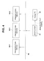
Fig. 4 shows an example configuration of an AV system to
which a data decoding system is applied. In this AV system, a
DVD player 61 plays back a DVD and outputs an analog video signal
to an analog television receiver 62, which displays pictures
corresponding to the received signal.
A plurality of (in this case, three) presentation
devices (for example, set-top boxes (STBs) for digital
satellite broadcast) 63-1 to 63-3 are connected to the DVD
player 61 via an AV bus 64.
The presentation devices 63-1 to 63-3 decode encoded
video data that is supplied from the DVD player 61 via the AV
bus 64.
For example, the AV bus 64 is one that is prescribed by
the IEEE (The Institute of Electrical and Electronic
Engineers) 1394 High Performance Bus Standard.
Fig. 5 shows internal configurations of the DVD player
61 and the presentation device 63-1 according to a first
embodiment. Although not shown in Fig. 5, the presentation
devices 63-2 and 63-3 are configured in the same manner as
the presentation device 63-1.
In the DVD player 61 of Fig. 5, presentation data that
is an MPEG program stream read out from a disc 101 by a disc
drive 71 is supplied to a presentation engine 12 and variable
rate control section (VBR control section) 72 whereas
navigation data is supplied to a navigation manager 11.
The variable rate control section 72 outputs supplied
data to a sub-DEMUX section 73 with such timing that the
presentation device 63-1 may immediately decode received
data. For example, a variable rate control section disclosed
in Japanese Patent Application No. Hei. 8-238781 by the
present assignee can be used as the variable rate control
section 72.
The sub-DEMUX section 73 judges the kind of supplied
data (packs) based on the value of a stream ID that is
written in a header of the supplied data. The sub-DEMUX
section 73 then eliminates a sub-picture pack and audio packs
other than an audio pack designated by the navigation manager
11, and outputs the other packs to a PS/TS converter 74
(converting means).
The program stream (PS) and the transport stream (TS)
are prescribed in the ISO/IEC 13818-1 1996 edition as formats
of MPEG2.
A program stream is constructed by forming one packet
every predetermined hour/minute by multiplexing digital
signals of video data, audio data, and additional information
data. The length of each packet is variable; its size can be
changed in accordance with the data size. Therefore,
respective packets have different sizes. For example, a
program stream can be realized by making such a presetting
that the above data are accommodated in a pack of 2 Kbytes.
In this case, if the data cannot be accommodated in 2 Kbytes,
a residual portion is accommodated in the next pack. If
there remains an unused region, a padding region is added to
form a 2-Kbyte pack.
In contrast, packets of a transport stream have a fixed
length (size). For example, contents are determined such
that each audio packet and each video packet are 188 bytes
and a transport stream is constructed by arranging audio
packets and video packets in the time axis direction. Since
in general video data has a larger size than audio data, a
transport stream is constructed by forming one group by 10
video packets, one audio packet, and one additional
information packet (12 packets in total), for example.
Therefore, PS-to-TS conversion is realized by
sequentially dividing variable-length PS packets into video
packets, audio packets, and additional information packets so
that they have a fixed length (e.g., 188 bytes) of TS packets
and arranging those packets in the time axis direction. In
this case, various kinds of headers etc. are added to satisfy
the TS packet format.
In the case of playing back disc on which audio data of
four languages of Japanese, English, French, and Chinese, for
instance, are recorded, packs of all languages recorded on
the disc 101 are supplied to the sub-DEMUX section 73 via the
variable rate control section 72. Therefore, when Japanese,
for instance, is a selected language, the sub-DEMUX section
73 eliminates the unnecessary packs (in this case, audio
packs of English, French, and Chinese) to reduce the data
transmission amount.
The PS/TS converter 74 converts MPEG data of a program
stream that is supplied from the sub-DEMUX section 73 into
MPEG data of a transport stream, which is output to a 1394
transmission/reception section 75 (transferring means).
The 1394 transmission/reception section 75 executes an
isochronous communication process according to the IEEE 1394
standard, and transmits resulting data to a
transmission/reception section 91 (receiving means) of the
presentation device 63-1.
Fig. 6 shows a packet structure of isochronous
communication. A packet of isochronous communication
consists of a packet header, a header CRC, a data field, and
a data CRC.
The packet header consists of "Data_length" representing
a data length, "Tag" representing the kind of format of data
that is transmitted by the packet concerned, "Channel"
indicating a channel number (one of 0 to 63) of the packet,
"Tcode" representing a process code, and a sync code "Sy"
that is prescribed by each application. The header CRC
(Header_CRC) is an error correcting code of the packet header
and the data CRC (Data_CRC) is an error correcting code of
the data field (Data field). The data field consists of a
CIP header and a real-time data. The real-time data is a
substantial data to be transmitted.
Fig. 7 shows a format of the CIP (common isochronous
packet) header. The CIP header consists of a transmission
node number SID, a packetizing unit DBS, a packetizing data
division number FN, the number QPC of quadlets that were
added to make the data length equal to a given fixed length
at the time of division (1 quadlet is 4 bytes), a flag SPH of
a source packet header, a counter DBC for detecting missing
of a packet, a signal format FMT, and a format-dependent
field FDF. "rsv" is a reserved region.
The 1394 transmission/reception section 75 receives a
signal corresponding to a user's manipulation which signal is
generated by a user interface sub-control section 97 of the
presentation device 63-1 and transmitted via the 1394
transmission/reception section 91 by an asynchronous
communication, and outputs the received signal to the
navigation manager 11.
Fig. 8 shows a structure of command and response packets
of asynchronous communication.
Each of these packets consists of a packet header and a
data block. In the packet header, "destination_ID" for
identification of a destination is provided first and
followed by "tl" (transmission level) representing a process
label, "rt" (retry code) representing retry reproduction, and
"tcode" (transaction code) and "pri" (priority) indicating
process codes. Further, "source_ID" representing a transfer
source is provided next and followed by "destination_offset"
representing low-order 48 bits of a transfer destination
address.
Further, "data_length" representing a data length and
"extended_tcode" representing other process codes are
provided next. Provided last is "header_CRC" that is an
error correcting code in the header.
The data block consists of CTS, CT/RC, HA, OPC, OPRs,
and "data_CRC" that is an error correcting code in the data.
CTS to OPRs are prescribed as shown in Figs. 9A and 9B. That
is, in transferring a command, CTS is set at "0" and CT/RC is
given a code representing the kind of request as shown in
Fig. 9A. For example, HA is given a destination ID in the
apparatus. OPC is given a command to be transferred, and
OPRs are given parameters.
In transferring a response, CTS is given "0" and CT/RC
is given a code representing the kind of response as shown in
Fig. 9B. HA is given an ID of a sender in the apparatus, and
OPC is given a code of a processed command. OPRs are given
parameters.
As described above, the 1394 transmission/reception
section 75, which can perform both isochronous communication
and asynchronous communication, transmits data by an
isochronous communication and transmits a command and a
response by an asynchronous communication.
Fig. 10 schematically shows isochronous communication.
In the isochronous communication, one of AV devices connected
to each other via a bus is made a root and the root transmits
a cycle start packet at the beginning of each cycle of 125
µs. Each Av device that performs isochronous communication
is assigned a particular time zone in each cycle, and
transmits data in the assigned time zone with a given channel
number. In this manner, in the isochronous communication,
communications are performed at constant time intervals.
A method for utilizing by navigation manager 11, through
an asynchronous communication, a signal corresponding to a
user's manipulation which signal is generated by the user
interface sub-control section 97 of the presentation device
63-1 may be one disclosed in Japanese Patent Application No.
Hei. 8-238761 by the present assignee.
Since the presentation engine 12 of the DVD player 61 is
configured in the same manner as that shown in Fig. 21, a
description therefor is omitted here. A D/A converter 43
converts a digital audio signal and a digital video signal
that are supplied from the presentation engine 12 into an
analog audio signal and an analog video signal, respectively,
which are output to the analog television receiver 62.
In the presentation device 63-1 shown in Fig. 5, the
1394 transmission/reception section 91 executes an
isochronous communication process according to the IEEE 1394
standard, thereby receiving data transmitted from the DVD
player 61 and outputs the received data to a DEMUX section
92.
Further, the 1394 transmission/reception section 91
transmits a signal corresponding to a user's manipulation
which signal is generated by the user interface sub-control
section 97 of the presentation device 63-1 to the 1394
transmission/reception section 75 of the DVD player 61
through an asynchronous communication.
The DEMUX section 92 judges the kind of supplied data
(packs) based on the value of a stream ID that is written in
a header of the supplied data, and outputs an audio pack and
a video pack to an audio decoder 93 and a video decoder 95,
respectively. Since a sub-picture pack and unnecessary audio
packs have been eliminated by the sub-DEMUX section 73, only
the audio pack and the video pack are supplied to the DEMUX
section 92.
The audio decoder 93 decodes an audio pack of an MPEG
transport stream that is supplied from the DEMUX section 92
or some other circuit (not shown; for instance, a receiving
circuit for digital satellite broadcast), and outputs a
decoded digital audio signal to a D/A converter 94.
The video decoder 95 decodes a video pack of an MPEG
transport stream that is supplied from the DEMUX section 92
or some other circuit (not shown), and outputs a decoded
digital video signal to a D/A converter 96.
The D/A converter 94 D/A-converts the supplied digital
audio signal and outputs a resulting analog audio signal to
a predetermined device (not shown).
The D/A converter 96 D/A-converts the supplied digital
video signal and outputs a resulting analog video signal to
the predetermined device.
Next, the operations of the DVD player 61 and the
presentation device 63-1 shown in Fig. 5 will be described.
First, the disc drive 71 reads out presentation data and
navigation data from the disc 101, and outputs the
presentation data to the presentation engine 12 and the
variable rate control section 72 and the navigation data to
the navigation manager 11.
Then, the variable rate control section 72 outputs the
supplied presentation data (audio pack, video pack, and sub-picture
pack) to the sub-DEMUX section 73 with such timing
that the presentation device 63-1 can immediately decode
received data.
The navigation manager 11 outputs such information as a
designated language of audio to the sub-DEMUX section 73 and
the presentation engine 12 in accordance with the navigation
data from the disc 101 and a user's manipulation.
The sub-DEMUX section 73 checks a stream ID of a packet
header of the data (pack) supplied from the variable rate
control section 72, and judges the kind of pack based on its
value.
Fig. 11 shows an example of a pack format. In this
format, a 14-byte pack header is provided at the head of the
pack and followed by a packet header, which is followed by a
region of one of video information, audio information, and
sub-picture information (compressed). In the case of a sub-picture
pack, a sub-stream ID region is provided between the
packet header and the sub-picture information region. A
padding region (not used for any specific purpose) for making
the pack length equal to a given fixed length is provided
after the above information.
Each pack is constituted in the above manner. A stream
ID is written at a given position (region) of the packet
header.
Fig. 12 shows an example of a correlation between stream
ID values and kinds of pack.
If the stream ID is "110x0n1n2n3b" (b is a binary number,
x is 0 or 1, and ni is 0 or 1), the pack concerned is a pack
of an (n1n2n3b)th MPEG audio stream, i.e., an audio pack.
If the stream ID is "11100000b," the pack concerned is
a pack of a video stream, i.e., a video pack.
If the stream ID is "10111101b," the pack concerned is
a pack designated by a sub-stream ID.
Fig. 13 shows an example of a correlation between sub-stream
ID values and kinds of pack.
If the sub-stream ID is "001n1n2n3n4n5b" (ni is 0 or 1),
the pack concerned is a pack of a (n1n2n3n4n5b)th sub-picture
stream, i.e., a sub-picture pack.
The sub-DEMUX section 73 judges the kind of pack
supplied from the variable rate control section 72 by
checking the values of the above-mentioned stream ID and sub-stream
ID, and eliminates the sub-picture pack and the audio
packs other than the audio pack designated by the navigation
manager 11 and outputs only the video pack and the audio pack
designated by the navigation manager 11 to the PS/TS
converter 74.
The PS/TS converter 74 converts the type of supplied
MPEG data (pack) from a program stream to a transport stream,
and outputs the MPEG data of a transport stream to the 1394
transmission/reception section 75.
The 1394 transmission/reception section 75 outputs the
MPEG data of a transport stream to the presentation device
63-1 through an isochronous communication.
In the above manner, the DVD player 61 eliminates given
audio packs and a sub-picture pack by using the sub-DEMUX
section 73, and converts program stream type MPEG data read
out from the disc 101 into transport stream type MPEG data,
which is output to the presentation device 63-1.
The 1394 transmission/reception section 91 of the
presentation device 63-1 receives the transport stream type
MPEG data from the DVD player 61 and outputs it to the DEMUX
section 92.
Like the sub-DEMUX section 73 of the DVD player 61, the
DEMUX section 92 checks values of a stream ID and a sub-stream
ID of the data and judges the kind of data (pack).
The DEMUX section 92 outputs the pack to the audio decoder 93
if it is an audio pack, and to the video decoder 95 if it is
a video pack.
If the pack concerned is an audio pack, the audio
decoder 93 decodes it and outputs a digital audio signal to
the D/A converter 94, which converts the digital audio signal
to an analog audio signal and outputs it.
On the other hand, if the pack concerned is a video
pack, the video decoder 95 decodes it and outputs a digital
video signal to the D/A converter 96, which converts the
digital video signal into an analog video signal and outputs
it.
In the above manner, the presentation device 63-1
decodes transport stream type MPEG data that is supplied from
the DVD player 61, thereby reproducing video data and audio
data recorded on the disc 101.
As described above, in the above embodiment, in
reproducing data recorded on the disc 101 by using the DVD
player 61 and the presentation device 63-1, the data type is
converted from a program stream to a transport stream in the
DVD player 61 and the transport stream type data is decoded
in the presentation device 63-1 by the audio decoder 93 or
the video decoder 95 depending on the data (audio or video).
Fig. 14 shows internal configurations of the DVD player
61 and the presentation device 63-1 according to a second
embodiment. Although not shown in Fig. 14, the presentation
devices 63-2 and 63-3 are configured in the same manner as
the presentation device 63-1.
In the DVD player 61, the PS/TS converter 74 of the DVD
player 61 of the first embodiment is removed and a 1394
transmission/reception section 75A (transferring means)
transfers program stream type MPEG data that is an output of
a sub-DEMUX section 73 to the presentation device 63-1 though
an isochronous communication.
Since the other components of the DVD player 61 are the
same as in the first embodiment, descriptions therefor are
omitted here.
In the presentation device 63-1, a 1394
transmission/reception section 91A (receiving means) receives
program stream type MPEG data that is transferred from the
DVD player 61 and outputs it to a PS/TS converter 98.
The PS/TS converter 98 converts MPEG data of a program
stream that is supplied from the 1394 transmission/reception
section 91A into MPEG data of a transport stream, which is
output to a DEMUX section 92.
Since the other components of the presentation device
63-1 are the same as in the first embodiment, descriptions
there for are omitted here.
Since the operation of the second embodiment is the same
as that of the first embodiment except that the process of
converting the type of MPEG data from a program stream to a
transport stream is moved to the presentation device 63-1
side, it is not described here.
Fig. 15 shows internal configurations of the DVD player
61 and the presentation device 63-1 according to a third
embodiment. Although not shown in Fig. 15, the presentation
devices 63-2 and 63-3 are configured in the same manner as
the presentation device 63-1.
Since the DVD player 61 is the same as that of the
second embodiment, it is not described here.
In the presentation device 63-1, the 1394
transmission/reception section 91A receives program stream
type MPEG data that is transmitted from the DVD player 61 and
outputs it to a separation circuit 121.
The separation circuit 121 (supplying means) outputs
MPEG data that is supplied from the 1394
transmission/reception section 91A or some other circuit (not
shown) to a DEMUX section 92 if it is of a transport stream
type and to a DEMUX section 122 if it is of a program stream
type.
The DEMUX section 122 checks a stream ID and a sub-stream
ID of the program stream type MPEG data that is
supplied from the separation circuit 121. Based on the
values of the stream ID and the sub-stream ID, the DEMUX
section 122 outputs an audio pack to an audio encoder 123
(first decoding means) which can deal with data of a program
stream and a video pack to a video decoder 125 (first
decoding means) which can deal with data of a program stream.
The audio decoder 123 and the video decoder 125 decode
the supplied audio pack and video pack and output decoded
digital signals to D/ A converters 124 and 126, respectively.
The D/ A converters 124 and 126 convert the supplied
digital audio signal and video signal into analog signals,
respectively, and output the analog signals.
Since the other components are the same as in the second
embodiment, they are not described here.
Next, the operation of the third embodiment will be
described. Since the operation of the DVD player 61 is the
same as in the second embodiment, only the operation of the
presentation device 63-1 will be described below.
The 1394 transmission/reception section 91A of the
presentation device 63-1 receives program stream type MPEG
data from the DVD player 61 and outputs it to the separation
circuit 121.
The separation circuit 121 outputs supplied MPEG data to
the DEMUX section 92 if it is of a transport stream type, and
to the DEMUX section 122 if it is of a program stream type.
If the supplied MPEG data is of a transport stream type,
the DEMUX section 92 checks values of a stream ID and a sub-stream
ID of the data and judges the kind of data (pack).
The DEMUX section 92 outputs the pack to the audio decoder 93
if it is an audio pack, and to the video decoder 95 if it is
a video pack.
The decoders 93 and 95 (second decoding means) decode
the audio pack and the video pack of a transport stream,
respectively, and the D/ A converters 94 and 96 convert
decoded data into analog signals and output the analog
signals.
On the other hand, if the supplied MPEG data is of a
program stream type (in the case where the data is supplied
from the DVD player 61), the DEMUX section 122 checks values
of a stream ID and a sub-stream ID of the data and judges the
kind of data (pack). The DEMUX section 122 outputs the pack
to the audio decoder 123 if it is an audio pack, and to the
video decoder 125 if it is a video pack.
The decoders 123 and 125 decode the audio pack and the
video pack of a transport stream, respectively, and the D/ A
converters 124 and 126 convert decoded data into analog
signals and output the analog signals.
As described above, the presentation device 63-1 of the
third embodiment has two systems of decoders so as to
accommodate both types of MPEG data.
Fig. 16 shows internal configurations of the DVD player
61 and the presentation device 63-1 according to a fourth
embodiment. Although not shown in Fig. 16, the presentation
devices 63-2 and 63-3 are configured in the same manner as
the presentation device 63-1.
In the DVD player 61 shown in Fig. 16, presentation data
that is an MPEG program stream read out from the disc 101 by
the disc drive 71 is supplied to the presentation engine 12
and navigation data is supplied to the navigation manager 11.
The presentation engine 12, which is configured in the
same manner as that shown in Fig. 3, outputs a digital video
signal and a digital audio signal to a D/A converter 43 and
a 1394 transmission/reception section 75B, respectively.
The 1394 transmission/reception section 75B transmits
the supplied digital video and audio signals to the
presentation device 63-1 by isochronous communication that is
prescribed by the IEEE 1394 standard.
Since the navigation manager 11 and the D/A converter 43
are configured in the same manner as in the third embodiment,
they will not be described here.
In the presentation device 63-1 of the fourth
embodiment, a 1394 transmission/reception section 91B
receives the digital video and audio signals transmitted from
the DVD player 61 and outputs data thereof to a D/A converter
131.
The D/A converter 131 converts the supplied data into
analog signals and outputs the analog signals.
Since a user interface sub-control section 97 is
configured in the same manner as in the third embodiment, it
is not described here.
Next, the operation of the fourth embodiment will be
described.
First, in the DVD player 61 shown in Fig. 16, the disc
drive 71 reads out presentation data as an MPEG program
stream from the disc 101 and supplies it to the presentation
engine 12 and supplies navigation data to the navigation
manager 11.
Then, the presentation engine 12 reproduces a digital
signal from the supplied presentation data according to
settings of the navigation manager 11 and outputs the
reproduced digital signal to the D/A converter 43 and the
1394 transmission/reception section 75B.
The 1394 transmission/reception section 75B transmits
supplied digital video and audio signals to the presentation
device 63-1 by isochronous communication that is prescribed
by the IEEE 1394 standard.
In the presentation device 63-1, the 1394
transmission/reception section 91B receives the digital video
and audio signals transmitted from the DVD player 61 and
outputs data thereof to the D/A converter 131.
The D/A converter 131 converts the supplied data into
analog signals and outputs the analog signals.
As described above, according to the fourth embodiment,
converted data of the DVD player 61 is supplied to the
presentation device 63-1 via the 1394 transmission/ reception
sections 75B and 91B that are interfaces prescribed by the
IEEE 1394 standard, and converted into analog signals there.
Fig. 17 shows an example configuration of a transport
stream system target decoder model (T-STD: standard decoder).
Based on a PID (packet identification) of a header portion of
an input transport stream, a video stream is supplied to a
decoder 144 via a transport buffer 141, a multiple buffer
142, and a video ES (elementary stream) buffer 143. The
video stream is decoded by a decoder 144 and output
therefrom. At this time, for display of a B-picture of the
MPEG scheme, an I-picture and a P-picture are delayed by a
reorder buffer 145.
An audio stream is supplied to a decoder 153 via a
transport buffer 151 and an audio main buffer 152. The audio
stream is decoded by the decoder 153 and output therefrom.
System information (PSI (program specific information)) is
supplied to a decoder 163 via a transport buffer 161 and a
system information main buffer 162. The system information
is decoded by the decoder 163 and output therefrom.
As for the basic process of the PS/TS conversion, first,
a pack header is removed from each pack and a PES (packetized
elementary stream) is divided into portions of 176 bytes (188
bytes - 12 bytes) that corresponds to a payload of a
transport stream (TS). At this time, for packet alignment,
stuffing is effected at the last portion of each PES.
Thereafter, each PES is packetized by adding a newly
generated TS packet header to it.
Care should be taken to satisfy the above-described T-STD
model so that a buffer of a decoder on the receiving side
does not overflow or underflow. From the viewpoint of the
buffer size, there occurs no problem because the T-STD model
has the same or larger buffer size, as described below.
That is, video data is 32 (= 8 + 24) Kbytes in the case
of a program stream and is 234 (= 0.5 + 9.5 + 224) Kbytes in
the case of a transport stream. Audio data is 4 Kbytes in
the case of a program stream and is also 4 Kbytes (= 0.5 +
3.5) Kbytes in the case of a transport stream.
However, the buffer of the T-STD is internally divided
into the transport buffer and the main buffer and a leak rate
between these buffers may cause a problem. As shown in Fig.
17, while the input rate is 10.08 Mbps that is the maximum
transfer rate of DVD-Video, in T-STD the leak rate of the
video transport buffer 141 is 18 Mbps (MP@ML) and the leak
rate of the audio transport buffer 151 is 2 Mbps. Therefore,
there occurs no problem for the video because the leak rate
of the transport buffer 141 is higher than its input rate.
However, in the audio transport buffer 151, since the
leak rate (2 Mbps) is lower than the input rate (10.08 Mbps),
the audio transport buffer 151 may overflow if data is
transferred without making any measure. To avoid this
problem, it is necessary to separate an audio stream,
temporarily effect buffering on it, and then multiplex it
with the other streams.
Fig. 18 shows internal configurations of the DVD player
61 and the presentation device 63-1 according to a fifth
embodiment. Although not shown in Fig. 18, the presentation
devices 63-2 and 63-3 are configured in the same manner as
the presentation device 63-1.
In the embodiment shown in Fig. 18, presentation data
read out from a disc 101 is supplied to either a VBR control
section 72A or a maximum rate control section 72B via a
switch 76. For example, when normal reproduction is
designated by a user's manipulation, presentation data
reproduced from the disc 101 is supplied to the VBR control
section 72A via the switch 76. Since the configuration and
the operation of the VBR control section 72A are the same as
the VBR control section shown in Fig. 5, they are not
described here.
On the other hand, when a trick play mode such as fast
feed, reverse reproduction, or double speed reproduction is
designated by a user's manipulation, information
corresponding to the user's manipulation is supplied to a
navigation manager 11 via a user interface control section
24. As a result, the navigation manager 11 detects entrance
into a trick play mode and controls the switch 76 so that
reproduction data from the disc 101 is supplied to the
maximum rate control section 72B.
In outputting data that is supplied from the disc 101
via the switch 76, the maximum rate control section 72B
performs a check so that a transfer rate that is secured in
advance in the IEEE 1394 standard is not exceeded.
That is, if it is judged that the above-mentioned
transfer rate will be exceeded, the maximum rate control
section 72B supplies, via the navigation manager 11, an
optical pickup (not shown) with a signal for instructing it
to suspend reading from the disc 101. In response, the
optical pickup stops data reading from the disc 101. When a
transfer-possible state is restored, the maximum rate control
section 72B supplies, via the navigation manager 11, the
optical pickup with a signal for instructing it to restart
the reading from the disc 101. In response, the optical
pickup restarts the data reading from the disc 101. In this
manner, the maximum rate control section 72B controls the
rate so as to prevent a failure in the transmission line.
Fig. 19 is a block diagram showing an example
configuration of a PS/TS converter 171 (converting means)
shown in Fig. 18. The internal configuration of the PS/TS
converter 171 shown in Fig. 19 is also applicable to the
above-described first and second embodiments, i.e., the PS/ TS
converters 74 and 98 shown in Figs. 5 and 14, respectively.
A pack/PES header analyzer 181 is supplied with pack
data of an MPEG-PS format that has been subjected to VBR
control or maximum rate control. The pack/PES header
analyzer 181 captures the pack data and stores it in a memory
(not shown), and checks the content of a pack/PES header.
The pack/PES header analyzer 181 detects a stream ID from
each pack header to distribute audio data, video data, and
sub-picture data based on the detected stream ID.
Further, the pack/PES header analyzer 181 supplies the
stream ID and other data to a PAT (program association
table)/PMT (program map table)/SIT (service information
table) generation section 191.
A SCR (system clock reference) detection section 187
detects a SCR by analyzing a pack header of pack data that is
supplied via the pack/PES header analyzer 181.
A PCR (program clock reference) generation section 189
generates a TS PCR by using a counter of 27 MHz that operates
in a STC (system time clock) generation circuit 188 on a disc
drive 71 side. STC initialization is performed by adding a
fixed delay to a first-output SCR. Initialization is also
effected when the STC is offset at the occurrence of a rush
of a block such as an angle block, a block-out, or the like.
A pack header elimination section 182 eliminates a pack
header to save the buffer capacity of the stage downstream of
the demultiplexer 183 (separating means). The demultiplexer
(DEMUX) 183 separates only an audio pack from pack data
supplied from the pack header elimination section 182 and
supplies it to a first buffer 185 (bufferl). The
demultiplexer 183 supplies the remaining packs, i.e., a video
pack, a sub-picture pack, and a navigation pack to a second
buffer 184 (buffer2).
An audio stream is temporarily accepted by the first
buffer 185 having a size of 4 Kbytes that is the PS audio
buffer size. A leak rate calculation/readout control section
186 calculates the output rate of the first buffer 185 so
that it becomes lower than or equal to 2 Mbps (leak rate of
the transport buffer 151 of T_ STD shown in Fig. 17), and
controls the readout to a TS packetization block (TS
packetization/MUX section) 192 (multiplexing means) in
accordance with the calculated rate.
A PCR insertion section 190 supplies a TS packet header
to the TS packetization block 192. The TS packetization
block 192 attaches a TS packet header to each pack by using
a default PID. Fig. 20 shows examples of contents of a
header. Fig. 21 shows examples of PIDs for a DVD.
As shown in Fig. 20, the first 8 bits of a TS packet
header are a sync byte (sync_byte) and "010000111" is set
there. The next one bit is an error indicator
(transport_error_indicator) and "0" or "1" is set there. The
next one bit is a unit start indicator
(payload_unit_start_indicator) and "0" or "1" is set there.
The next one bit indicates packet priority
(transport_priority) and "0" or "1" is set there.
The next 13 bits are a PID and a value as shown in Fig.
18 is set there in accordance with the kind of packet. The
next 2 bits indicates a scrambling control
(transport_scrambling_control) and "00" is set there. The
next 2 bits indicates an adaptation field control
(adaptation_field_control) and "01" or "11" is set there.
The next 4 bits are a continuity counter (continuity_counter)
and information to be used to detect whether a packet having
the same PID has been discarded halfway is set there.
In the case of an MPEG2-TS that does not include any
adaptation field (hence there is no PCR), a TS packet header
is constructed by the above 4 bytes. On the other hand, in
the case of an MPEG2-TS that includes an adaptation field
(hence there exists a PCR), the following information is set
additionally. The first 8 bits of the adaptation field are
an adaptation field length and "00000111" (= 7) is set there.
The next one bit is a discontinuity indicator
(discontinuity_indicator) and "0" or "1" us set there.
The next one bit is a random access indicator
(random_access_indicator) and "0" is set there. The next one
bit is a stream priority indicator (ES_priority_indicator)
and "0" is set there.
The next one bit is "PCR (program clock reference)_flag"
and "1" is set there. The next one bit is "OPCR (original
program clock reference)_ flag" and "0" is set there. The
next one bit is "splicing_point_flag" and "0" is set there.
The next one bit is "transport_private_data_flag" and "0" is
set there.
A PCR is set at the next 48 bits. More specifically,
the first 33 bits are "program_clock_reference_flag," the
next 6 bits are "reserved," i.e., a reserved region, and the
last 9 bits are "PCR_extension."
As shown in Fig. 21, a video pack (VIDEO_PACK) is
assigned a PID "0x0020" ("0x" indicates that "0020" is a
hexadecimal number), and an audio pack (AUDIO_PACK) is
assigned PIDs "0x0021" to "0x0028." A sub-picture pack
(SP_PACK) is assigned PIDs "0x0029" to "0x0048." "PCI
(program chain information)_PKT" is assigned a PID "0x0049,"
and "DSI (decoder system information_PKT" is assigned a PID
"0x004a."
Although the user private area of the PIDs shown in Fig.
21 is "0x0010" to "0x1FFE," in view of the compatibility with
the STB (set-top box) it is avoided to use the area "0x0010"
to "0x0016" which is used by the STB; "0x0020" to "0x004a"
are used for a DVD.
The PAT/PMT/SIT generation section 191 generates various
tables such as a PAT, a PMT, a SIT and a DIT (discontinuity
information table) based on a stream ID etc. detected from
each pack header. The TS packetization block 192 multiplexes
audio data from the first buffer 185, video data from the
second buffer 184, sub-picture data, table information from
the PAT/PMT/SIT generation section 191, and PCR etc. from the
PCR insertion section 190, to thereby generate a transport
stream packet.
Next, the operation of the fifth embodiment will be
described. Only the operations of the portion relating to
the maximum rate control section 72B and the PS/TS converter
171 will be described below because the other portion of the
DVD player 61 operates basically in the same manner as in the
first embodiment which was described above with reference to
Fig. 5. The operations of the presentation device 63-1 to
63-3 will not be described below because they operate in the
same manner as described above with reference to Fig. 5.
For example, when normal reproduction is designated by
a user's manipulation, presentation data reproduced from the
disc 101 is supplied to the VBR control section 72A via the
switch 76. Since the configuration and the operation of the
VBR control section 72A are the same as the VBR control
section 72 shown in Fig. 5, they are not described here.
On the other hand, when a trick play mode such as fast
feed, reverse reproduction, or double speed reproduction is
designated by a user's manipulation, information
corresponding to the user's manipulation is supplied to the
navigation manager 11 via the user interface control section
24. As a result, the navigation manager 11 detects entrance
into a trick play mode and controls the switch 76 and
switches its internal connection so that reproduction data
from the disc 101 is supplied to the maximum rate control
section 72B.
In outputting MPEG2 format data that is supplied from
the disc 101 via the switch 76, the maximum rate control
section 72B performs a check so that a transfer rate (maximum
rate) that is secured in advance in the IEEE 1394 is not
exceeded.
That is, if it is judged that the maximum rate will be
exceeded, the maximum rate control section 72B supplies, via
the navigation manager 11, the optical pickup (not shown)
with a signal for instructing it to suspend reading from the
disc 101. In response, the optical pickup stops data reading
from the disc 101. When a transfer-possible state is
restored, the maximum rate control section 72B supplies, via
the navigation manager 11, the optical pickup with a signal
for instructing it to restart the reading from the disc 101.
In response, the optical pickup restarts the data reading
from the disc 101. In this manner, the maximum rate control
section 72B controls the rate so as to prevent a failure in
the transmission line.
The data that has been rate-controlled by the VBR
control section 72A or the maximum rate control section 72B
is supplied to the sub-DEMUX section 73, where unnecessary
packs are eliminated. Resulting data is supplied to the
PS/TS converter 171.
The data thus supplied to the PS/TS converter 171 is
input to the pack/PES header analyzer 181. This data is pack
data of an MPEG-PS format that has been subjected to the VBR
control or the maximum rate control. The pack/PES header
analyzer 181 captures this data and stores it in a memory
(not shown), and checks the content of a pack/PES header.
The pack/PES header analyzer 181 detects a stream ID from
each pack header to distribute audio data, video data, and
sub-picture data based on the detected stream ID.
Further, the stream ID and other data are supplied to
the PAT/PMT/SIT generation section 191.
Also supplied with the pack data via the pack/PES header
analyzer 181, the SCR detection section 187 detects a SCR by
analyzing a pack header of the pack data. The detected SCR
is supplied to the PCR generation section 189.
The PCR generation section 189 generates a TS PCR by
using a counter of 27 MHz that operates in the STC generation
circuit 188 on the disc drive 71 side. STC initialization is
performed by adding a fixed delay to a first-output SCR.
Initialization is also effected when the STC is offset at the
occurrence of a rush of a block such as an angle block, a
block-out, or the like.
The pack header elimination section 182 eliminates a
pack header from the pack data supplied from the pack/PES
header analyzer 181 to save the buffer capacity of the stage
downstream of the demultiplexer 183. The remaining data is
supplied to the demultiplexer (DEMUX) 183. The demultiplexer
183 separates only an audio pack from pack data supplied from
the pack header elimination section 182 and supplies it to
the first buffer 185 (buffer1). The remaining packs, i.e.,
a video pack, a sub-picture pack, and a navigation pack are
supplied to the second buffer 184 (buffer2).
An audio stream is temporarily accepted by the first
buffer 185 having a size of 4 Kbytes that is the PS audio
buffer size. The leak rate calculation/readout control
section 186 calculates the output rate of the first buffer
185 so that it becomes lower than or equal to 2 Mbps, and
controls the readout to the TS packetization block (TS
packetization/MUX section) 192 in accordance with the
calculated rate.
The output-timing-controlled audio data will be
converted into a TS packet and again multiplexed with the
other streams (video data etc.). If the other streams are
delayed for this multiplexing, there arises a possibility
that the decoder side video buffer underflows. In view of
this, the rate after the multiplexing is determined to 12.08
(= 10.08 + 2.0) Mbps in consideration of the audio leak rate.
Therefore, the TS packetization block 192 also receives,
via the second buffer 185, video data and other streams (for
instance, sub-picture data) and multiplexes those data with
such timing that no collision occurs with audio packs. At
this time, since the output rate is increased by the audio
leak rate as described above, transfers of video data and
other data are not delayed.
The final transfer rate after the TS conversion is
increased by a value of redundancy corresponding to addition
of a TS packet header and table information such as a PAT, a
PMT, and a SIT.
Since the above process for audio data is necessary for
each audio stream, buffers of 32 Kbytes (=4 Kbytes x 8) are
needed at the maximum, i.e., in outputting all audio streams.
The PCR insertion section 190 supplies a TS packet
header to the TS packetization block 192. A PCR is attached
once per at least 100 milliseconds, as prescribed in the
MPEG2-TS standard.
The TS packetization block 192 attaches a TS packet
header to each pack by using a default PID. The PAT/PMT/SIT
generation section 191 generates various tables such as a
PAT, a PMT, a SIT, and a DIT (discontinuity information
table) based on a stream ID etc. detected from each pack
header, and these tables are supplied to the TS packetization
block 192. The TS packetization block 192 multiplexes audio
data from the first buffer 185, video data from the second
buffer 184, sub-picture data, table information from the
PAT/PMT/SIT generation section 191, and PCR etc. from the PCR
insertion section 190, to thereby generate a transport stream
packet.
In the above manner, program stream type MPEG data is
converted into transport stream type MPEG data in the PS/TS
converter 171 and output therefrom. At this time, audio data
and other data such as video data and sub-picture data are
temporarily stored in the respective buffers (buffer1 and
buffer2) and again multiplexed so as not to cause the decoder
side audio buffer to overflow. Therefore, even when the
input rate is 10.08 Mbps, sound can be reproduced without
interruption.
The invention is not limited to the above embodiments,
and can be applied to other apparatuses and systems.
Further, specific numerical values appearing in the
above embodiments are merely examples and the invention is
not limited to those values.
As described above, in the data decoding system and the
data decoding method, the first
device converts data of a first form into data of a second
form and then transmits the data of the second form, or the
second device receives the data of the first form and
converts it into data of a second form, and the second device
decodes the data of the second form. Therefore, data
recorded on a DVD can be reproduced by using a device having
a decoder suitable for processing of a transport stream.
In the data decoding system,
the first device reproduces data recorded on a given
recording medium and transfers the reproduced data via an
IEEE 1394 interface, and the plurality of second devices
receive the data transferred via the IEEE 1394 interface and
perform digital-to-analog conversion on the received data, to
output an analog signal. Therefore, data recorded on a DVD
can be reproduced.
In the transfer device and the transfer method,
data of a first form is converted into data
of a second form that is a data form in a decoder, and the
data of the second form is transferred. Therefore, data
recorded on a DVD can be reproduced by using a device having
a decoder suitable for processing of a transport stream.
In the receiving device and the receiving method,
data of a first form is received,
the data of the first form is converted into data of a second
form that is a data form in a decoder, and the data of the
second form is decoded. Therefore, data recorded on a DVD
can be reproduced.
In the receiving device and the receiving method,
data of a first form or a second
form is received and supplied to the first decoding section
or the second decoding section in accordance with a form of
the received data. The first decoding means decodes the data
of the first form, or the second decoding means decodes the
data of the second form. Therefore, data recorded on a DVD
can be reproduced.
In summary, embodiments of the invention relate to a
data decoding system and method, a transfer device and
method, and a receiving device and method in which in
transmitting data via a digital interface a data form is
converted, on a transmission or reception side, to a form
suitable for a decoder on the reception side.