EP0834291A2 - Medizinisches oder dentales Handinstrument - Google Patents
Medizinisches oder dentales Handinstrument Download PDFInfo
- Publication number
- EP0834291A2 EP0834291A2 EP97116813A EP97116813A EP0834291A2 EP 0834291 A2 EP0834291 A2 EP 0834291A2 EP 97116813 A EP97116813 A EP 97116813A EP 97116813 A EP97116813 A EP 97116813A EP 0834291 A2 EP0834291 A2 EP 0834291A2
- Authority
- EP
- European Patent Office
- Prior art keywords
- hand instrument
- coupling
- handpiece
- instrument according
- handle part
- Prior art date
- Legal status (The legal status is an assumption and is not a legal conclusion. Google has not performed a legal analysis and makes no representation as to the accuracy of the status listed.)
- Granted
Links
- 230000008878 coupling Effects 0.000 claims abstract description 92
- 238000010168 coupling process Methods 0.000 claims abstract description 92
- 238000005859 coupling reaction Methods 0.000 claims abstract description 92
- 239000012530 fluid Substances 0.000 claims abstract description 19
- XLYOFNOQVPJJNP-UHFFFAOYSA-N water Substances O XLYOFNOQVPJJNP-UHFFFAOYSA-N 0.000 claims abstract description 14
- 239000003795 chemical substances by application Substances 0.000 claims description 28
- 238000003860 storage Methods 0.000 claims description 27
- 239000000843 powder Substances 0.000 claims description 21
- 238000007789 sealing Methods 0.000 claims description 15
- 241001631457 Cannula Species 0.000 claims description 9
- 238000005299 abrasion Methods 0.000 claims description 5
- 230000035515 penetration Effects 0.000 claims description 5
- 239000007788 liquid Substances 0.000 claims description 4
- 239000003086 colorant Substances 0.000 claims description 2
- 238000011144 upstream manufacturing Methods 0.000 claims description 2
- 238000004519 manufacturing process Methods 0.000 description 7
- 239000000203 mixture Substances 0.000 description 7
- 239000003082 abrasive agent Substances 0.000 description 5
- 238000013461 design Methods 0.000 description 5
- 239000000463 material Substances 0.000 description 5
- YCKRFDGAMUMZLT-UHFFFAOYSA-N Fluorine atom Chemical compound [F] YCKRFDGAMUMZLT-UHFFFAOYSA-N 0.000 description 4
- 210000003811 finger Anatomy 0.000 description 4
- 229910052731 fluorine Inorganic materials 0.000 description 4
- 239000011737 fluorine Substances 0.000 description 4
- 210000003128 head Anatomy 0.000 description 4
- 229910052751 metal Inorganic materials 0.000 description 4
- 239000002184 metal Substances 0.000 description 4
- 238000013459 approach Methods 0.000 description 3
- 238000011109 contamination Methods 0.000 description 3
- 238000002845 discoloration Methods 0.000 description 3
- 239000011521 glass Substances 0.000 description 3
- 210000000214 mouth Anatomy 0.000 description 3
- 239000002245 particle Substances 0.000 description 3
- 239000004033 plastic Substances 0.000 description 3
- 206010010774 Constipation Diseases 0.000 description 2
- UIIMBOGNXHQVGW-UHFFFAOYSA-M Sodium bicarbonate Chemical compound [Na+].OC([O-])=O UIIMBOGNXHQVGW-UHFFFAOYSA-M 0.000 description 2
- 230000009286 beneficial effect Effects 0.000 description 2
- 230000008901 benefit Effects 0.000 description 2
- 238000010276 construction Methods 0.000 description 2
- 230000006872 improvement Effects 0.000 description 2
- 239000012535 impurity Substances 0.000 description 2
- 238000003825 pressing Methods 0.000 description 2
- 210000003813 thumb Anatomy 0.000 description 2
- 235000005979 Citrus limon Nutrition 0.000 description 1
- 244000131522 Citrus pyriformis Species 0.000 description 1
- 241000233866 Fungi Species 0.000 description 1
- 229910000831 Steel Inorganic materials 0.000 description 1
- 239000006061 abrasive grain Substances 0.000 description 1
- 230000009471 action Effects 0.000 description 1
- 230000006978 adaptation Effects 0.000 description 1
- 238000004026 adhesive bonding Methods 0.000 description 1
- 238000004140 cleaning Methods 0.000 description 1
- 239000002131 composite material Substances 0.000 description 1
- 239000010431 corundum Substances 0.000 description 1
- 229910052593 corundum Inorganic materials 0.000 description 1
- 210000003298 dental enamel Anatomy 0.000 description 1
- 239000000645 desinfectant Substances 0.000 description 1
- 238000011161 development Methods 0.000 description 1
- 230000018109 developmental process Effects 0.000 description 1
- 238000006073 displacement reaction Methods 0.000 description 1
- 239000000945 filler Substances 0.000 description 1
- 239000000796 flavoring agent Substances 0.000 description 1
- 235000019634 flavors Nutrition 0.000 description 1
- 239000003292 glue Substances 0.000 description 1
- 238000003780 insertion Methods 0.000 description 1
- 230000037431 insertion Effects 0.000 description 1
- 238000009434 installation Methods 0.000 description 1
- 150000002739 metals Chemical class 0.000 description 1
- 244000052769 pathogen Species 0.000 description 1
- 238000005498 polishing Methods 0.000 description 1
- OTYBMLCTZGSZBG-UHFFFAOYSA-L potassium sulfate Chemical compound [K+].[K+].[O-]S([O-])(=O)=O OTYBMLCTZGSZBG-UHFFFAOYSA-L 0.000 description 1
- 229910052939 potassium sulfate Inorganic materials 0.000 description 1
- 235000011151 potassium sulphates Nutrition 0.000 description 1
- 239000010453 quartz Substances 0.000 description 1
- VYPSYNLAJGMNEJ-UHFFFAOYSA-N silicon dioxide Inorganic materials O=[Si]=O VYPSYNLAJGMNEJ-UHFFFAOYSA-N 0.000 description 1
- 229910000030 sodium bicarbonate Inorganic materials 0.000 description 1
- 235000017557 sodium bicarbonate Nutrition 0.000 description 1
- 241000894007 species Species 0.000 description 1
- 230000000087 stabilizing effect Effects 0.000 description 1
- 239000010959 steel Substances 0.000 description 1
- 239000000126 substance Substances 0.000 description 1
- 230000008719 thickening Effects 0.000 description 1
- 230000007704 transition Effects 0.000 description 1
- 239000012780 transparent material Substances 0.000 description 1
- 230000001960 triggered effect Effects 0.000 description 1
Images
Classifications
-
- A—HUMAN NECESSITIES
- A61—MEDICAL OR VETERINARY SCIENCE; HYGIENE
- A61C—DENTISTRY; APPARATUS OR METHODS FOR ORAL OR DENTAL HYGIENE
- A61C3/00—Dental tools or instruments
- A61C3/02—Tooth drilling or cutting instruments; Instruments acting like a sandblast machine
- A61C3/025—Instruments acting like a sandblast machine, e.g. for cleaning, polishing or cutting teeth
Definitions
- the invention relates to a medical or dental Hand instrument according to the preamble of claim 1, 17, 20 or 21.
- the handpiece described in US 2,814,877 has on its rear end of a container for the treatment agent on.
- the coupling connection for the supply line is on arranged rear end of the storage container, the Feed line extends coaxially through the container.
- the handpiece is fixed from several longitudinal sections composite body.
- a valve is arranged in the feed line, manually by a protruding actuator can either be opened or closed.
- the Exit opening is at the front end of a Handpiece protruding cannula, the free end with respect to the Longitudinal center axis of the hand instrument obliquely to the front runs.
- a dental hand instrument described in US 4,648,840 differs from the construction methods described above laterally protruding storage container, the one in the rear End region of the hand instrument is arranged.
- An existing hand instrument has i.a. two demands too fulfill. For one, it should be easy to use to deal with as little effort as possible with his hand instrument Being able to move and guide use in a targeted and safe manner. To the another is a simple and inexpensive to manufacture Construction shown, taking into account in particular of the available relatively small installation space is essential. It must be taken into account that the supply line between that of the supply line associated coupling part and the hand instrument associated coupling part and the continuing Feed line is complicated and to manufacture this Feed line sections a relatively large Manufacturing and time is required, which also high manufacturing costs are specified.
- the invention is based, with one Hand instrument in the preamble of claim 1 described type the coupling for coupling to the Simplify or improve the supply line.
- the associated coupling part and one or more coaxially or axially parallel, sealed pipe socket couplings on a separate Inserted part that is simple and inexpensive prefabricated and assembled.
- the handpiece can be in the area the coupling connection is designed much simpler will. This is because the manufacture of the Supply line on the one hand on the separate insert part and others in the hand instrument with the insert removed better accessibility is easier and easier. For this also bears the design of between the insert and the handpiece single or multiple pipe socket coupling at who manufacture themselves in a simple manner as well can seal and allows a small design.
- this embodiment according to the invention enables a use of the insert as an adapter to adapt the Hand instruments to different, the supply line associated coupling parts if several insert parts are provided, which differ from coupling parts Manufacturers fit. This is a simple adjustment of the Hand instruments to different manufacturers of Supply lines or device manufacturers possible easy to use and quick and inexpensive can be carried out.
- the invention is further based on the object medical or dental hand instrument in the preamble of claim 17 specified type so that a easier and better handling is possible.
- the deposits on body parts, especially teeth or discoloration can be of different types and strengths be.
- the invention is therefore based on the object a hand instrument in the preamble of claim 20 and / or 21 described type so that the relevant body part can be treated specifically and / or the hand instrument to the treatment required is customizable.
- treatment agents different abrasion capacity can be used optionally.
- a Treatment agent fine, medium or coarse Removability e.g. with a Treatment agent fine, medium or coarse Removability.
- the invention is further based on the object To protect the interior of the handpiece from contamination.
- the invention is further based on the object Hand instrument in the preamble of claim 25 Describe the type described so that contamination the clutch is prevented.
- the invention is further based on the object Hand instrument in the preamble of claim 27 described type so that regardless of the Position of the hand instrument a substantially uniform Mixture of the carrier fluid and the abrasive Treatment agent is achieved.
- the inlet opening is for the transport fluid and the inner outlet opening for the Mixture in the middle of the receiving chamber of the Storage container.
- these openings are in a zone of the reception chamber in which, regardless of the Position of the hand instrument a substantially uniform Mix quantity and concentration through the inner outlet opening can flow out.
- the invention also relates to a advantageous pressure relief device for the Storage container, which is a clean opening of the storage container even possible if this is under pressure, e.g. at the Presence of constipation in the area of the Hand instruments.
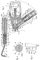
- the main parts of the hand instrument 1 are rod-shaped Handpiece 2, a storage container 3 for a powder abrasive treatment agent in the back of the Hand instrument 1 is arranged, a coupling connection 4 for detachable coupling of the hand instrument 1 to a flexible Supply line of a treatment chair or the like, an outlet opening 5 in the front end region of the Handinstruments 1 and feed lines, which differ from the Coupling connection 4 through the hand instrument 1 to Extend outlet opening 5.
- this is the case Handpiece 2 from a front handpiece part, the one Handle part 6 forms, and a rear handpiece part that a shaft 7 extending rearward from the grip part 6 forms the reservoir 3 at its rear end carries, and on which the coupling connection 4 in lateral Position is arranged.
- the grip part 6 and the shaft 7 are sleeve-shaped bodies, in whose cavity 8 is preferably round or a cross-section several supply lines to the outlet opening 5 extend from the coupling connection 4.
- the present embodiment there are two Supply lines 9, 11 are present, namely one for one Compressed gas, especially compressed air, and one for one Treatment liquid, especially water.
- the one in the area of the lateral coupling connection 4 Feed line sections 9a, 11a open into the rear End area and with respect to the storage container 3 on one line connection 9c, 11c offset in the front in further Line sections or here in the cavity 8.
- the feed line sections 9a, 11a preferably obliquely and converging towards the front Sleeve thickening into which a connecting piece 12 is molded on, in particular in the predetermined inclined position, the one with the longitudinal central axis 10 of the handpiece 2 Angle W, here from approximately 40 to 60 °, in particular approximately 45 ° to 55 °, includes.
- the hand instrument 1 is used, for example, pads, especially on teeth, by means of a nozzle or Outlet opening 5 flowing out under pressure, powdery Particle-containing stream to clean what else is described. If small as an abrasive agent in the stream hard grains, e.g. Abrasive grains or corundum grains are used the hand instrument is also suitable for removal harder tissue such as tooth enamel, e.g. to round off sharp edges or height adjustments. Depending on Hardness of the grains including filler materials or metals from crowns or inlays are machined.
- the coupling connection 4 is part of a screw coupling or preferably plug-in / rotary coupling 13 with which the Coupling connection 4 to the flexible, not shown Supply line easy to use and quick to remove can be coupled.
- the plug / rotary coupling 13 includes one cylindrical coupling pin and a receiving it cylindrical coupling recess 14, with the present embodiment of the hinted Coupling pin from a connector part of the flexible Supply line protrudes and the coupling recess 14 in Connection piece 12 is arranged.
- the insert 20 is by one on the Connector 12 detachably screwed union nut 24th held.
- a Locking device 25 For releasably securing the plug-in / rotary coupling 13 is a Locking device 25 with a resilient Locking element 25a provided that in a Locking recess either in the coupling pin 14a or in the coupling recess 14b can be resiliently latched and released the plug-in / rotary coupling 13 can be pushed over.
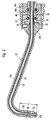
- the outlet opening 5 is at the free end of a straight or sideways slant or cross extending cannula 27 arranged, the free end with the Longitudinal central axis 10 of the hand instrument 1 a right or obtuse angle W 1 includes.
- the cannula 27 is through a Outer tube 27a formed, the rear end fixed to one hollow cylindrical cannula foot 27b is connected by a Quick connection, here a bayonet lock 31, with the front end of the grip sleeve 6 is releasably connectable.
- Bayonet lock 31 has a in a conventional manner Locking pin, here in the form of a radial pin 29 on Cannula foot 24b on, by inserting and rotating the cannula 27 insertable in a bayonet groove of the grip sleeve 6 preferably also lockable into a locking recess is so that an unwanted turning back is prevented.
- Locking pin here in the form of a radial pin 29 on Cannula foot 24b on, by inserting and rotating the cannula 27 insertable in a bayonet groove of the grip sleeve 6 preferably also lockable into a locking recess is so that an unwanted turning back is prevented.
- the receiving sleeve 33 are in one rear stepped bore an inner tube 34 and an outer tube 35 firmly and tightly attached, of which the inner tube 34th coaxially into the central region of the receiving space 36 of the Storage container 3 extends.
- the outer tube 35 that the Surrounding inner tube 34 with a ring spacing extends to to a cylindrical connecting part 37 in which a Line connection between the line section 9b and the forming a continuation line section 11b Ring channel realized between the inner and outer tubes 35 is.
- the connector is to the cross-sectional size of the Cavity 8 adapted and against an axial displacement therein secured by suitable fastening measures, e.g. by Glue or a locking cross pin or one Safety cross screw.
- suitable fastening measures e.g. by Glue or a locking cross pin or one Safety cross screw.
- Connection hole 38 is arranged, which inwardly in a front step hole 39 extends into which the rear end of the outer tube 35 extends and is sealed, e.g. by pressing.
- an annular groove 40 in the lateral surface of the Connector 37 is provided, and there may be more Connection holes 38 may be arranged distributed over the circumference.
- connection hole 38 Connector 37 This is on both sides of the connection hole 38 Connector 37 in the cavity 8 by one Sealing ring 41 sealed in an associated annular groove in the lateral surface of the connecting piece 37 or in the Inner surface of the cavity 8 sits.
- the axial securing of the Connector 37 can also be done in that it by means of the outer tube 35 axially immovable on the Receiving sleeve 33 is held.
- the feed line bypasses in the area of the receiving sleeve 33 11 the free end of the cannula foot 27b. This is done by that of a rear tube receiving the outer tube 35 Stepped hole 42 in the receiving sleeve 33 one or more on the Radial channels 43 arranged circumferentially distributed, the or in an approximately axially parallel in the receiving sleeve 33 arranged longitudinal channel 44a open up to Cannula foot 27b extends and through a transverse channel 44b in the Receiving sleeve 33 and a transverse channel 45 connected to it Cannula foot 27b connected to the cavity of the outer tube 27a is.
- An inner tube 51 is located in the outer tube 27a of the cannula 27, whose outer cross-sectional size is smaller than that Inner cross-sectional size of the outer tube 27a, so that there is a gap 52 between the latter and the inner tube 51.
- this gap 52 is an annular gap.
- the inner tube 51 extends up to the free end portion of the outer tube 27a, with it the latter can complete, can lag behind or something can protrude as shown.
- the configuration is the free end region of the inner tube 51 in a preferably convergent cap 53 held with the facing end of the outer tube 27a is screwed, is screwed in particular with a threaded shoulder 54.
- the cap 53 surrounds the inner tube 51 with one with the small one Gap 52 comparable distance. In order to make the Outflow, it is advantageous at the free end of the gap 52 to form a gap enlargement 52a.
- the cross-sectional size of the threaded pipe 51 is advantageous to have the cross-sectional size of the threaded pipe 51 to taper a distance a from its free end.
- the cross section of the inner tube 51 is reduced and the flow and exit velocity of the flowing medium, here water, increases what the Performance of the abrasive treatment contributes and also the mixing of the media with the abrasive improved.
- the cross-sectional taper 55 should preferably not gradual but gradual or conical to a Avoid edge prone to clogging.
- its inner cross section is somewhat dimensioned larger, which reduces the risk of constipation becomes. In the present embodiment, the distance is a about 5 to 10 mm.
- the gap 52 settles in the area of the cannula foot 27b to behind the transverse hole 45, with the outer tube 27a receiving longitudinal hole 30, if necessary in stages is large.
- the rear end of the inner tube 51 is tightly connected to the rear end of the cannula foot 27b, e.g. pressed or soldered when the cannula foot 27b and that Inner tube 51 are made of metal.
- the rear end of the inner tube 51 in its End area somewhat thickened and in the longitudinal hole 30 or in one Step enlargement of the same pressed in, tightness is preserved.
- a preferred sleeve-shaped sealing ring 56 is provided which in the bottom of the Plug-in recess 32 sits, preferably the front end of the inner tube 34 into the hole of the sealing ring 56 protrudes into the outer cross section of the inner tube 34 is adjusted.
- the length of the sealing ring 56 is somewhat dimensioned larger than the distance between the inner tubes 34 and 51 or between the inner tube 34 and the cannula foot 27b.
- the reservoir 3 forms the rear end of the Hand instrument 1, wherein it is arranged coaxially to the handpiece 2 and has a hat-shaped cover 61, which by a in screw thread 62 arranged in its free edge region a flat or annular container base 63 screwable is.
- the container base 63 is preferably pot-shaped formed, whereby the receiving space 64 of the storage container 3 is enlarged.
- the lid 61 is preferably made of transparent material, e.g. Glass, quartz or plastic.
- the inner tube 34 passes through the connector 37 in Stepped hole 39, being in the rear section of the stepped hole 39 is closely recorded.
- the one behind the connector 37 located part of the cavity 8 is towards the receiving space 64 closed by a sleeve 65 which the inner tube 34 with surrounds an annular gap 66, the inner tube 34 extending up to one or in an inner shoulder 67 in the rear end region of the Sleeve 65 extends.
- the annular gap 66 places one to the rear directed extension of the cavity 8.
- the sleeve 65 tightly inserted into the hole formed by the cavity 8 or screwed in.
- the Sleeve 65 dimensioned smaller in cross section than that Cross section of the cavity 8 and it has a flange 68 with an external thread 69, which is in an internal thread of the Cavity 8 is screwed.
- the flange 68 itself or a support ring 71 inserted therein holds the rear end portion of the inner tube 37 in the axial position.
- the support ring 71 has a longitudinal perforation or through holes 72, to allow air to pass into the annular gap 66 guarantee.
- In the sleeve 65 are in one preferably middle with respect to the receiving space 64 Position a plurality of transverse holes 73 that the annular gap 66 with connect the recording space 64.
- the central axis 10 has a plurality of, in this case three transverse holes 73 provided, of which the or a middle, approximately radially and the one in front and the one in back extend divergent obliquely.
- the cross holes 73 can also be distributed around the circumference.
- the sleeve 65 has at least one axial entry hole 74, which is coaxial with the free Inner cross section of the inner tube 34 is arranged.
- the entry hole 74 is a Upstream disc 75, which forms radial access holes 74a.
- the disc is part of a Nut that has a corresponding recess on the thread rear end of the sleeve 65 is screwed.
- the handle part 6 and the shaft 7 are in a rotary bearing 78 the longitudinal central axis 10 rotatable relative to one another stored, at the same time by a Connecting device 79 are held axially to one another.
- the Pivot bearing 78 is by a suitable overlap Sleeve body of the grip part 6 and the shaft 7 formed.
- the grip part 6 has one of protruding coaxially at its rear end, preferably tapered sleeve shoulder 81 on that of a protruding Sleeve jacket 82 of the shaft 7 with little movement is surrounded.
- the connecting device 79 is by a Locking device 83 with at least one radial after externally directed latching lug 84 to one of the sleeve approach 81 rearward protruding locking arm 85, the Locking lug 84 a locking edge on the inside of the Engages sleeve attachment 82.
- On the back the Latch arm 85 a convergent insertion surface 86, which automatically insert the elastic locking arms 85 causes.
- the sleeve attachment 82 is preferably convergent towards the front or with a conical lateral surface 87a, wherein it is approximately finally merges into the lateral surface 87 of the handle part 6.
- the outer surface 87 is for the purpose of improving the grip provided with a handle structure.
- Ring shafts 88 and ring recesses are provided are preferably rounded and only slightly inclined Merge ring flank surfaces into one another.
- the lateral surface 87b has an improvement in the grip strength three evenly distributed over the circumference Grip surfaces 89, which is an advantageous three-point bracket the grip part 6 between three fingers of the operating hand allow while the shaft 7 on the metacarpal area especially between the index finger and the thumb can. The contact point results in the shaft 7 nearby the connecting piece 12.
- the rotatability of the handle part 6 enables adaptation of the Position of the cannula 27 at the respective treatment site. To the Twist only needs the handle 6 with which it gripping fingers to be twisted, the cannula 27th is also rotated.
- the shaft 7 lies on the base area between the index finger and the thumb of the back of the hand. Due to the weight of the flexible supply line can the shaft 7 when turning the grip sleeve 6 in its respective Turn position remain.
- the Treatment liquid in the feed line 11 and Compressed air in the feed line 9 through the Flow rotary / plug coupling into the handpiece 2 the Compressed air initially flows backwards through the annular gap 66 and preferably distributed in the transverse holes 72 in the Recording space 64 flows and the abrasive therein Means, e.g. Sodium bicarbonate or potassium sulfate in Powder form, whirls up.
- the air / powder mixture thus formed flows through the entry hole 74 or when present a disk 75 through the access holes 74a and through the Entry hole 74 in the inner sleeve 34 and on to Outlet opening 5, where it mixes with the water and one abrasive current to remove deposits on teeth and the like forms.
- the media supply described above can be triggered by a suitable switch.
- a foot switch is provided which electrically corresponding opening valves one Control device for the media operated.
- a check valve 91 arranged, the valve body, preferably a Valve ball, a backflow in the supply line section 11a locks.
- other hand instruments 1, e.g. Turbine which is also connected to the plug-in / rotary coupling 13 can be coupled, against contamination and damage from the abrasive is protected.
- the abrasive material could e.g. due to dead weight after switching off the hand instrument 1 or in the following fault in the area of Get plug / rotary coupling 13.
- the check valve 91 is preferably in the region of the Bottom of a front step hole 91a arranged in each with a sleeve forming the pipe socket 17, 18 Distance to the check valve 91 receiving stage fixed is inserted.
- the storage container 3 has a special one Pressure relief device 92, which is a pressure relief guaranteed before the reservoir 3 is opened here the cover 61 is removed.
- the pressure relief device 92 points in the cooperating with the sealing ring 94 Sealing surface 95 on a recess 96 which when unscrewing the lid 61 a small passage for those under pressure forms standing compressed air through which it can flow out, before the cover comes out of the thread engagement. At this There is hardly any powder discharge under pressure relief especially not when the cover 61 in one with the exit opening thus formed pointing upward of the hand instrument in which the powder is located the bottom of the lid.
- the at least one flat 97 needs only outdoors Edge region of the ring approach to be arranged. You can however also over the entire length of the ring shoulder 99 extend, the thread also a flat having.
- the abrasive is made of a material that is in Moisture or water dissolves, and therefore relatively easily from the treatment site here the oral cavity of the Patient to rinse again.
- a pleasant flavor to mix e.g. Lemon or orange taste.
- a powder with a grain size between about 15 is suitable ⁇ m and 125 ⁇ m very good for removing and cleaning deposits on teeth.
- the covering or the pollution or the discoloration of the Teeth of different strength or strength it is advantageous to use several types of powder different abrasion capacity or more abrasive Performance of the hand instrument 1 in one Allocate storage containers. It is also beneficial to powder in several different grain sizes or ranges, such as coarse, medium and fine or coarse and fine, in storage containers to provide. In the latter case e.g. the powder for rough work has a grain size of 60 ⁇ m to 100 ⁇ m, while the powder for fine work has a grain size between Can have 15 microns and 50 microns. The latter grain size is suitable for fine work on sensitive teeth as well also for polishing teeth.
- the species in different Making colors are provided several different cannulas 27 or cannula heads 53 are present that determine Powder types are assigned, it is advantageous to use the cannulas or the cannula heads with a corresponding mark provided, which indicates the affiliation of the suitable powder.
- This marking is preferably a color marking in the same color as the associated powder.
- Exit hole 73 and / or entry hole 74 formed Outlet and / or inlet nozzles for the carrier air flow and / or for assign the mixture of air and abrasive, which ever are interchangeable according to the desired grain size of the powder.
- a set of parts consisting of a cannula 27 and an outlet and / or inlet nozzle, here the sleeve-shaped nozzle carrier 15, with respect to the Passages must be coordinated.
- the insert part 20, the cannula 21, the receiving sleeve 33, the connector 37, the inner and outer tubes 34, 35 and the sleeve 65 and optionally also the disk 75 made of hard material Metal, preferably steel, causing early wear of these parts is avoided.
- the handle part 6 and / or Shaft 7 and / or the cover 61 or the storage container 3 consist of metal, plastic or preferably glass. These materials can also be used in difficult designs simple and inexpensive to manufacture, and they are insensitive to disinfectants and sterilizers. In addition, there is no electrostatic, especially with glass Charging.
- abrasive powdered fluorine or a fluorine-containing agent in particular also in Powder form, to be mixed. This ensures that the Treatment fluorine penetrates the tooth surface and this hardened and stabilized. Due to the Flow velocity and the resulting Impact of the fluorine-containing particles is the action particularly effective in the tooth surface.
Landscapes
- Health & Medical Sciences (AREA)
- Oral & Maxillofacial Surgery (AREA)
- Dentistry (AREA)
- Epidemiology (AREA)
- Life Sciences & Earth Sciences (AREA)
- Animal Behavior & Ethology (AREA)
- General Health & Medical Sciences (AREA)
- Public Health (AREA)
- Veterinary Medicine (AREA)
- Dental Tools And Instruments Or Auxiliary Dental Instruments (AREA)
Abstract
Description
- Fig. 1
- ein erfindungsgemäßes medizinisches oder insbesondere zahnärztliches Handinstrument im vertikalen Längsschnitt;
- Fig. 2
- eine Kanüle des Handinstruments im vertikalen Längsschnitt;
- Fig. 3
- den Schnitt III-III in Fig. 1;
- Fig. 4
- die in Fig. 1 mit X gekennzeichnete Einzelheit in der Draufsicht.
Claims (31)
- Medizinisches oder dentales Handinstrument (1) mitdadurch gekennzeichnet,einem Handstück (2) und einem am Handstück (2) angeordneten Griffteil (6),einer bezüglich des Griffteils (6) vorderseitig angeordneten Auslaßöffnung (5) für den Austritt eines abrasiven Behandlungsmittels und eines Transportfluids,und einem Kupplungsanschluß (4) zum Ankuppeln des Handinstruments (1) an eine Versorgungsleitung für wenigstens ein Transportfluid, insbesondere Wasser und/oder Luft,wobei der Kupplungsanschluß (4) ein Kupplungsteil (14b) einer Kupplung (13) ist,
daß das Kupplungsteil (14b) an einem Einsatzteil (20) angeordnet ist, das in eine Steckfassung oder Steckausnehmung (19) einsteckbar ist und in seinem stromabseitigen Endbereich eine oder mehrere koaxial oder axparallel angeordnete, abgedichtete Rohrstutzen-Kupplungen (10) aufweist, die jeweils eine Zuführungsleitung (9, 11) für das Transportfluid mit einer weiterführenden Zuführungsleitung (21, 22) verbinden. - Handinstrument nach Anspruch 1,
dadurch gekennzeichnet,
daß vom Einsatzteil (20) Rohrstutzen (17,18) vorragen, die jeweils in einem weiterführenden Zuführungsleitungskanal (21, 22) stecken. - Handinstrument nach Anspruch 1 oder 2,
dadurch gekennzeichnet,
daß die Kupplung (13) durch eine Steckkupplung mit einem Steckzapfen (14a) und eine ihn aufnehmende Steckausnehmung (14b) gebildet ist, wobei die Steckausnehmung (14b) im Einsatzteil (20) oder in dem Kupplungsteil angeordnet ist, das zur Versorgungsleitung gehört - Handinstrument nach einem der vorherigen Ansprüche,
dadurch gekennzeichnet,
daß die Zuführungsleitung oder die Zuführungsleitungen (9, 11) die Teilungsfuge zwischen dem Kupplungszapfen (14a) und dem die Kupplungsausnehmung (14b) aufweisenden Teil an Durchdringungsstellen Z-förmig durchsetzen und die Durchdringungsstellen beidseitig durch jeweils einen Dichtungsring (16) abgedichtet sind. - Handinstrument nach einem der vorherigen Ansprüche,
dadurch gekennzeichnet,
daß der Kupplungsanschluß (4) seitlich am Handstück (2) angeordnet ist. - Handinstrument nach Anspruch 5,
dadurch gekennzeichnet,
daß die Mittelachse des Kupplungsanschlusses und die Längsmittelachse (10) des Handstücks (2) einen rechten oder nach vorne spitzen Winkel (W) einschließen. - Handinstrument nach einem der vorherigen Ansprüche,
dadurch gekennzeichnet,
daß mehrere Einsatzteile (20) vorgesehen sind, die zu unterschiedlich ausgebildeten oder geformten, der Versorgungsleitung zugehörigen Kupplungsteilen passen. - Handinstrument nach einem der vorherigen Ansprüche,
dadurch gekennzeichnet,
daß es einen Vorratsbehälter (3) für das abrasive Behandlungsmittel, insbesondere Pulver, aufweist, der mit der Zuführungsleitung (9, 11) verbunden ist, wobei vorzugsweise der Vorratsbehälter (3) im hinteren Bereich des Handinstruments (1) angeordnet ist. - Handinstrument nach einem der vorherigen Ansprüche,
dadurch gekennzeichnet,
daß der Kupplungsanschluß (4) insgesamt oder zumindest der Fußbereich des Kupplungsanschlusses (4) bezüglich dem Vorratsbehälter (3) nach vorne versetzt angeordnet ist. - Handinstrument nach einem der vorherigen Ansprüche,
dadurch gekennzeichnet,
daß der Kupplungsanschluß (4) zwei Zuführungsleitungen (9, 11) aufweist, vorzugsweise eine für die Behandlungsflüssigkeit, insbesondere Wasser, und die andere für ein Gas, insbesondere Luft. - Handinstrument nach Anspruch 10,
dadurch gekennzeichnet,
daß die Zuführungsleitung (9b) für Gas rückseitig von der Zuführungsleitung (11a) für Behandlungsflüssigkeit angeordnet ist. - Handinstrument nach einem der Ansprüche 8 bis 11,
dadurch gekennzeichnet,
daß der Vorratsbehälter (3) am hinteren Ende des Handstücks (2) und insbesondere koaxial zum Griffteil (6) angeordnet ist, vorzugsweise das hintere Ende bildet. - Handinstrument nach einem der Ansprüche 8 bis 12,
dadurch gekennzeichnet,
daß der Vorratsbehälter (3) einen lösbaren Deckel (61) aufweist, wobei die Teilungsfuge des Deckels (61) sich vorzugsweise quer, insbesondere rechtwinklig zur Längsmittelachse (10) des Handinstruments (1) erstreckt. - Handinstrument nach einem der vorherigen Ansprüche 8 bis 13,
dadurch gekennzeichnet,
daß eine Zuführungsleitung (9) für das Transportfluid mit einem vorzugsweise axialen Einlaßrohr (65) sich in den Vorratsbehälter (3) erstreckt, insbesondere in dessen mittleren Bereich endet. - Handinstrument nach einem der vorherigen Ansprüche 8 bis 14,
dadurch gekennzeichnet,
daß eine Zuführungsleitung (9) für das Transportfluid mit einem Auslaßrohr (34) vom Vorratsbehälter (3) ausgeht, das in den Vorratsbehälter (3) ragt, vorzugsweise in dessen mittleren Bereich ragt. - Handinstrument nach Anspruch 14 oder 15,
dadurch gekennzeichnet,
daß sich das Einlaßrohr (65) vorzugsweise vom hinteren Ende des Handstücks (2) nach hinten in den Vorratsbehälter (3) erstreckt und das Auslaßrohr (34) koaxial angeordnet ist, insbesondere im Einlaßrohr (65) angeordnet ist. - Medizinisches oder dentales Handinstrument (1) mitdadurch gekennzeichnet,einem Handstück (2) und einem am Handstück (2) angeordneten Griffteil (6),einer bezüglich des Griffteils (6) vorderseitig angeordneten Auslaßöffnung (5) für den Austritt eines abrasiven Behandlungsmittels und eines Transportfluidsund einem Kupplungsanschluß (4) zum Ankuppeln des Handinstruments (1) an eine Versorgungsleitung für wenigstens ein Transportfluid, insbesondere Wasser und/oder Luft,oder Handinstrument nach einem der vorherigen Ansprüche,
daß das Handstück (2) in seinem vorderen Bereich ein Griffteil (6) aufweist, von dem sich der Schaft (7) nach hinten erstreckt und daß das Griffteil (6) und der Schaft (7) um deren Längsmittelachse (10) frei drehbar aneinander gelagert sind. - Handinstrument nach Anspruch 17,
dadurch gekennzeichnet,
daß die Griffhülse (6) einen rückseitigen Hülsenansatz (81) aufweist und der Schaft (7) einen vorderseitigen Hülsenansatz (82) aufweist, wobei die Hülsenansätze (81, 82) einander mit geringem Bewegungsspiel koaxial übergreifen, wobei vorzugsweise der Hülsenansatz (82) des Schaftes (7) den Hülsenansatz (81) des Griffteils (6) übergreift. - Handinstrument nach Anspruch 17 bis 18,
dadurch gekennzeichnet,
daß das Griffteil (6) und der Schaft (7) durch eine Schnellschlußverbindung, vorzugsweise eine Verrastungsvorrichtung (83), aneinander gehalten sind. - Medizinisches oder dentales Handinstrument (1) mitdadurch gekennzeichnet,einem Handstück (2) und einem am Handstück (2) angeordneten Griffteil (6),einer bezüglich des Griffteils (6) vorderseitig angeordneten Auslaßöffnung (5) für den Austritt eines abrasiven Behandlungsmittels und eines Transportfluidsund einem Kupplungsanschluß (4) zum Ankuppeln des Handinstruments (1) an eine Versorgungsleitung für wenigstens ein Transportfluid, insbesondere Wasser und/oder Luft,oder Handinstrument nach einem der vorherigen Ansprüche,
daß das Handinstrument (1) mit mehreren, in Vorratsbehältern angeordneten abrasiven Behandlungsmitteln unterschiedlicher Abtragfähigkeit eine Behandlungseinrichtung bilden. - Medizinisches oder dentales Handinstrument (1) mitdadurch gekennzeichnet,einem Handstück (2) und einem am Handstück (2) angeordneten Griffteil (6),einer bezüglich des Griffteils (6) vorderseitig angeordneten Auslaßöffnung (5) für den Austritt eines abrasiven Behandlungsmittels und eines Transportfluidsund einem Kupplungsanschluß (4) zum Ankuppeln des Handinstruments (1) an eine Versorgungsleitung für wenigstens ein Transportfluid, insbesondere Wasser und/oder Luft,oder Handinstrument nach einem der vorherigen Ansprüche,
daß die Auslaßöffnung (5) an einer Kanüle (27) oder einem Kanülenkopf (53) angeordnet ist, die bzw. der durch eine Schnellschlußverbindung, insbesondere einen Bajonettverschluß, oder eine Schraubverbindung mit dem Handstück (2) lösbar verbunden ist, wobei vorzugsweise mehrere Kanülen (27) oder Kanülenköpfe (53) unterschiedlicher Form und/oder Größe und/oder Auslaßöffnungsgröße (5) austauschbar vorgesehen sind. - Handinstrument nach Anspruch 20 oder 21,
dadurch gekennzeichnet,
daß sich die Arten der Behandlungsmittel durch eine unterschiedlich große Körnung unterscheiden und vorzugsweise drei unterschiedliche Behandlungsmittel für eine Grob- Mittel- und Feinbehandlung vorgesehen sind. - Handinstrument nach einem der Ansprüche 20 bis 22,
dadurch gekennzeichnet,
daß einer bestimmten Körnung des Behandlungsmittels eine bestimmte Größe der Auslaßöffnung (5) zugeordnet ist und die Kanülen (27) oder Kanülenköpfe (53) eine die Zugehörigkeit zum zugehörigen Behandlungsmittel kennzeichnende Markierung aufweisen, wobei vorzugsweise die unterschiedlichen Arten der Behandlungsmittel unterschiedliche Farben aufweisen und die Kanülen (27) oder Kanülenköpfe ( 53) eine Markierung mit der zugehörigen gleichen Farbe aufweisen. - Medizinisches oder dentales Handinstrument (1) mitdadurch gekennzeichnet,einem Handstück (2) und einem am Handstück (2) angeordneten Griffteil (6),einer vorderseitig vom Griffteil (6) angeordneten Auslaßöffnung (5) für den Austritt eines abrasiven Behandlungsmittels,und einem Kupplungsanschluß (4) zum Ankuppeln des Handinstruments (1) an eine Versorgungsleitung für wenigstens ein Transportfluid, insbesondere Wasser und/oder Luft,oder Handinstrument (1) nach einem der vorherigen Ansprüche,
daß der Innenraum (8) des Handstücks (2) durch eine Leitungsverbindung (101) mit der Zuführungsleitung (9) für das Gas verbunden ist. - Medizinisches oder dentales Handinstrument (1) mitdadurch gekennzeichnet,einem Handstück (2), einem am Handstück (2) angeordneten Griffteil (6),
einer vorderseitig vom Griffteil (6) angeordneten Auslaßöffnung (5) für den Austritt eines abrasiven Behandlungsmittels,und einem Kupplungsanschluß (4) zum Ankuppeln des Handinstruments (1) an eine Versorgungsleitung für wenigstens ein Transportfluid, insbesondere Wasser und/oder Luft,oder Handinstrument (1) nach einem der vorherigen Ansprüche,
daß in der Zuführungsleitung (9a) ein Rückschlagventil (91) in einer dem Kupplungsanschluß (4) vorgeordneten Position angeordnet ist. - Handinstrument nach Anspruch 25,
dadurch gekennzeichnet,
daß das Rückschlagventil (91) in einem ein Kupplungsteil (14b) aufweisendes Einsatzteil (2) angeordnet ist. - Medizinisches oder dentales Handinstrument (1) mitdadurch gekennzeichnet,einem Handstück (2) und einem am Handstück (2) angeordneten Griffteil (6),einer vorderseitig vom Griffteil (6) angeordneten Auslaßöffnung (5) für den Austritt eines abrasiven Behandlungsmittels,einem Kupplungsanschluß (4) zum Ankuppeln des Handinstruments (1) an eine Versorgungsleitung für wenigstens ein Transportfluid, insbesondere Wasser und/oder Luft,und einem Vorratsbehälter (3),in den eine Zuführungsleitung (66) mit wenigstens einer Einlaßöffnung (73) mündet,und der durch wenigstens eine innere Auslaßöffnung (74) und eine Verbindungsleitung (9) mit der Auslaßöffnung (5) am Griffteil (6) verbunden ist,oder Handinstrument nach einem der vorherigen Ansprüche,
daß die Einlaßöffnung (73) und die innere Auslaßöffnung (74) im mittleren Bereich des Aufnahmeraums (64) des Vorratsbehälters (3) angeordnet sind. - Handinstrument nach Anspruch 27,
dadurch gekennzeichnet,
daß die Zuführungsleitung (66) oder die Verbindungsleitung (9) durch einen Ringkanal gebildet ist und die jeweils andere Leitung koaxial innerhalb des Ringkanals verläuft. - Handinstrument nach einem der Ansprüche 27 oder 28,
dadurch gekennzeichnet,
daß dein axiale Abstand zwischen der Einlaßöffnung (73) und der Auslaßöffnung (74) gering ist, insbesondere nicht größer als etwa 30mm, vorzugsweise nicht größer als etwa 10mm bis 15mm ist. - Handinstrument nach einem der Ansprüche 27 bis 29,
dadurch gekennzeichnet,
daß die innere Auslaßöffnung (74) hinter der Einlaßöffnung (73) angeordnet ist. - Handinstrument nach einem der Ansprüche 27 bis 30,
dadurch gekennzeichnet,
daß die Zuführungsleitung (66) und die Verbindungsleitung (9) durch eine sich in den Aufnahmeraum (64) des Vorratsbehälters (3) erstreckende Doppelhülse gebildet sind.
Priority Applications (2)
| Application Number | Priority Date | Filing Date | Title |
|---|---|---|---|
| EP99115976A EP0958792B1 (de) | 1996-09-27 | 1997-09-26 | Medizinisches oder dentales Handinstrument |
| EP01122742A EP1177774B1 (de) | 1996-09-27 | 1997-09-26 | Medizinisches oder dentales Handinstrument |
Applications Claiming Priority (2)
| Application Number | Priority Date | Filing Date | Title |
|---|---|---|---|
| DE19639871 | 1996-09-27 | ||
| DE19639871 | 1996-09-27 |
Related Child Applications (1)
| Application Number | Title | Priority Date | Filing Date |
|---|---|---|---|
| EP99115976A Division EP0958792B1 (de) | 1996-09-27 | 1997-09-26 | Medizinisches oder dentales Handinstrument |
Publications (3)
| Publication Number | Publication Date |
|---|---|
| EP0834291A2 true EP0834291A2 (de) | 1998-04-08 |
| EP0834291A3 EP0834291A3 (de) | 1999-03-10 |
| EP0834291B1 EP0834291B1 (de) | 2000-03-22 |
Family
ID=7807152
Family Applications (3)
| Application Number | Title | Priority Date | Filing Date |
|---|---|---|---|
| EP97116813A Expired - Lifetime EP0834291B1 (de) | 1996-09-27 | 1997-09-26 | Medizinisches oder dentales Handinstrument |
| EP01122742A Expired - Lifetime EP1177774B1 (de) | 1996-09-27 | 1997-09-26 | Medizinisches oder dentales Handinstrument |
| EP99115976A Expired - Lifetime EP0958792B1 (de) | 1996-09-27 | 1997-09-26 | Medizinisches oder dentales Handinstrument |
Family Applications After (2)
| Application Number | Title | Priority Date | Filing Date |
|---|---|---|---|
| EP01122742A Expired - Lifetime EP1177774B1 (de) | 1996-09-27 | 1997-09-26 | Medizinisches oder dentales Handinstrument |
| EP99115976A Expired - Lifetime EP0958792B1 (de) | 1996-09-27 | 1997-09-26 | Medizinisches oder dentales Handinstrument |
Country Status (5)
| Country | Link |
|---|---|
| US (3) | US6416321B2 (de) |
| EP (3) | EP0834291B1 (de) |
| JP (1) | JP3345316B2 (de) |
| AT (3) | ATE190824T1 (de) |
| DE (4) | DE59709123D1 (de) |
Cited By (4)
| Publication number | Priority date | Publication date | Assignee | Title |
|---|---|---|---|---|
| EP1022993A1 (de) | 1997-10-17 | 2000-08-02 | Dentsply International Inc. | Abrasionshandstück zur verwendung mit einem abrasionssystem |
| EP1145689A3 (de) * | 2000-04-13 | 2002-01-02 | Nakanishi Inc. | Dentalmedizinisches Handstück zur Injektion von Therapeutikum enthaltende Pulver |
| US7011521B2 (en) | 2002-03-22 | 2006-03-14 | Ferton Holding S.A. | Dental handpiece |
| EP2537484A1 (de) * | 2011-06-22 | 2012-12-26 | Ferton Holding SA | Mischvorrichtung für ein dentales Pulverstrahlgerät sowie ein dentales Handinstrument für ein Pulverstrahlgerät mit einer entsprechenden Mischvorrichtung |
Families Citing this family (100)
| Publication number | Priority date | Publication date | Assignee | Title |
|---|---|---|---|---|
| JP3345316B2 (ja) | 1996-09-27 | 2002-11-18 | カルテンバハ アンド フォイト ゲー エム ベー ハー アンド カンパニー | 医薬又は歯科医療のための手器具 |
| DE10013210A1 (de) | 2000-03-17 | 2001-09-20 | Kaltenbach & Voigt | Vorrichtung zum Erkennen von Karies, Plaque, bakteriellen Befall, Konkrementen, Zahnstein und anderen fluoreszierenden Substanzen an Zähnen |
| WO2002011948A1 (en) | 2000-08-04 | 2002-02-14 | Danville Manufacturing Inc. | Hand-holdable gas/abrasion apparatus |
| CA2341105A1 (en) | 2001-03-21 | 2002-09-21 | Unknown | System and method for detection and removal of dental tartar, e.g. subgingival tartar |
| US7232262B2 (en) * | 2002-07-18 | 2007-06-19 | Westover Scientific, Inc. | Fiber-optic endface cleaning apparatus and method |
| US6821025B2 (en) * | 2002-07-18 | 2004-11-23 | Westover Scientific, Inc. | Fiber-optic endface cleaning assembly and method |
| WO2004037108A1 (de) * | 2002-10-23 | 2004-05-06 | Kaltenbach & Voigt Gmbh & Co. Kg | Kanüle für ein medizinisches oder dentalmedizinisches handstück zum aussprühen eines abrasiven strömungsmittels |
| US6863719B2 (en) * | 2002-12-30 | 2005-03-08 | Lexmark International, Inc. | Ink jet ink with improved reliability |
| US7147468B2 (en) * | 2002-12-31 | 2006-12-12 | Water Pik, Inc. | Hand held oral irrigator |
| US20040202980A1 (en) * | 2003-04-14 | 2004-10-14 | Policicchio Piero A. | Dental prophylaxis and air appliance |
| US20050169717A1 (en) * | 2004-02-03 | 2005-08-04 | Field Grant A. | Electronic drill depth indicator |
| US7172418B2 (en) * | 2004-04-14 | 2007-02-06 | James Edward Hamman | Powder applicator for teeth |
| WO2006041116A1 (ja) * | 2004-10-14 | 2006-04-20 | Ichiro Sugimoto | 電動歯ブラシ |
| US8388523B2 (en) | 2005-04-01 | 2013-03-05 | Welch Allyn, Inc. | Medical diagnostic instrument having portable illuminator |
| AU2006232534B2 (en) | 2005-04-01 | 2011-10-06 | Welch Allyn, Inc. | Vaginal speculum |
| US20070203439A1 (en) | 2006-02-24 | 2007-08-30 | Water Pik, Inc. | Water jet unit and handle |
| US8142352B2 (en) | 2006-04-03 | 2012-03-27 | Welch Allyn, Inc. | Vaginal speculum assembly having portable illuminator |
| US7670141B2 (en) | 2006-07-07 | 2010-03-02 | Water Pik, Inc. | Oral irrigator |
| USD802120S1 (en) | 2007-02-27 | 2017-11-07 | Water Pik, Inc. | Tip for oral irrigator |
| JP5074867B2 (ja) * | 2007-09-13 | 2012-11-14 | 株式会社ナカニシ | 歯科用ハンドピース |
| DE202008004615U1 (de) * | 2007-11-26 | 2008-07-10 | Dentaco Dentalindustrie Und -Marketing Gmbh | Vorrichtung zum Applizieren eines pulverförmigen oder flüssigen Stoffes |
| US20100190132A1 (en) | 2009-01-28 | 2010-07-29 | Water Pik, Inc. | Oral irrigator tip |
| US10258442B2 (en) | 2009-03-20 | 2019-04-16 | Water Pik, Inc. | Oral irrigator appliance with radiant energy delivery for bactericidal effect |
| US9061096B2 (en) | 2009-12-16 | 2015-06-23 | Water Pik, Inc. | Powered irrigator for sinus cavity rinse |
| USD629884S1 (en) | 2009-12-16 | 2010-12-28 | Water Pik, Inc. | Powered irrigator for sinus cavity rinse |
| USD670373S1 (en) | 2010-12-16 | 2012-11-06 | Water Pik, Inc. | Powered irrigator for sinus cavity rinse |
| WO2014059362A2 (en) | 2012-10-11 | 2014-04-17 | Water Pik, Inc. | Interdental cleaner using water supply |
| USD707350S1 (en) | 2012-10-11 | 2014-06-17 | Water Pik, Inc. | Handheld water flosser |
| EP2931171B1 (de) | 2012-12-17 | 2018-08-15 | 3M Innovative Properties Company | Vorrichtung zur ausgabe von dentalmaterial mit verriegelungsmechanismus |
| EP2742897A1 (de) | 2012-12-17 | 2014-06-18 | 3M Innovative Properties Company | Düsenkopf, Handstück und Pulverstrahlvorrichtung zum Aufbringen eines Dentalmaterials |
| EP2742898A1 (de) * | 2012-12-17 | 2014-06-18 | 3M Innovative Properties Company | Pulverstrahlvorrichtung zur Ausgabe von Dentalmaterial |
| CN105263436B (zh) * | 2013-03-07 | 2018-10-12 | 株式会社中西 | 具有喷嘴连接结构的牙科手机 |
| USD717427S1 (en) | 2013-03-14 | 2014-11-11 | Water Pik, Inc. | Handle for water flosser |
| USD714929S1 (en) | 2013-03-14 | 2014-10-07 | Water Pik, Inc. | Base for water flosser |
| USD725770S1 (en) | 2013-03-14 | 2015-03-31 | Water Pik, Inc. | Reservoir for water flosser |
| US9642677B2 (en) | 2013-03-14 | 2017-05-09 | Water Pik, Inc. | Oral irrigator with massage mode |
| USD788907S1 (en) | 2013-03-14 | 2017-06-06 | Water Pik, Inc. | Water flosser base unit with reservoir lid |
| CA2982642C (en) | 2013-11-27 | 2020-03-10 | Water Pik, Inc. | Oral irrigator with slide pause switch |
| US9980793B2 (en) | 2013-11-27 | 2018-05-29 | Water Pik, Inc. | Oral hygiene system |
| CN203693808U (zh) | 2013-12-12 | 2014-07-09 | 洁碧有限公司 | 牙科用喷水器 |
| US9532706B2 (en) | 2014-08-07 | 2017-01-03 | Welch Allyn, Inc. | Vaginal speculum with illuminator |
| US9743999B2 (en) | 2014-08-29 | 2017-08-29 | Piero A. Policicchio | Dental prophylaxis device and air appliance |
| CN205586102U (zh) | 2014-12-01 | 2016-09-21 | 洁碧有限公司 | 防水无线口腔冲洗器 |
| USD772397S1 (en) | 2014-12-01 | 2016-11-22 | Water Pik, Inc. | Oral irrigator with a charging device |
| USD772396S1 (en) | 2014-12-01 | 2016-11-22 | Water Pik, Inc. | Handheld oral irrigator |
| USD780908S1 (en) | 2015-11-03 | 2017-03-07 | Water Pik, Inc. | Handheld oral irrigator |
| USD822196S1 (en) | 2016-01-14 | 2018-07-03 | Water Pik, Inc. | Oral irrigator |
| USD804018S1 (en) | 2016-07-19 | 2017-11-28 | Water Pik, Inc. | Base for an oral irrigator |
| USD782656S1 (en) | 2016-01-25 | 2017-03-28 | Water Pik, Inc. | Oral irrigator |
| USD802747S1 (en) | 2016-07-19 | 2017-11-14 | Water Pik, Inc. | Reservoir for oral irrigator |
| USD786422S1 (en) | 2016-01-25 | 2017-05-09 | Water Pik, Inc. | Oral irrigator |
| CN114732551A (zh) | 2016-01-25 | 2022-07-12 | 洁碧有限公司 | 减小形状因子的口腔冲洗器 |
| USD783809S1 (en) | 2016-01-25 | 2017-04-11 | Water Pik, Inc. | Oral irrigator handle |
| USD796028S1 (en) | 2016-07-19 | 2017-08-29 | Water Pik, Inc. | Oral irrigator |
| USD794773S1 (en) | 2016-07-19 | 2017-08-15 | Water Pik, Inc. | Oral irrigator |
| USD819956S1 (en) | 2016-01-25 | 2018-06-12 | Water Pik, Inc. | Kit bag |
| US10835356B2 (en) | 2016-01-25 | 2020-11-17 | Water Pik, Inc. | Swivel assembly for oral irrigator handle |
| DE102016201693B4 (de) | 2016-02-04 | 2018-03-08 | Ferton Holding S.A. | Pulverkammer, Verschluss für eine Pulverkammer sowie Pulverstrahlgerät |
| USD804016S1 (en) | 2016-02-05 | 2017-11-28 | Water Pik, Inc. | Handheld oral irrigator |
| USD809650S1 (en) | 2016-02-22 | 2018-02-06 | Water Pik, Inc. | Oral irrigator |
| USD783810S1 (en) | 2016-02-22 | 2017-04-11 | Water Pik, Inc. | Handle for an oral irrigator |
| KR20170100997A (ko) | 2016-02-26 | 2017-09-05 | 비엔엘바이오테크 주식회사 | 치과용 치료기구 |
| USD802119S1 (en) | 2016-03-02 | 2017-11-07 | Water Pik, Inc. | Oral irrigator |
| KR102397188B1 (ko) | 2016-03-02 | 2022-05-12 | 워터 피크 인코포레이티드 | 구강 세정기용 작동 조립체 |
| USD782657S1 (en) | 2016-03-02 | 2017-03-28 | Water Pik, Inc. | Oral irrigator handle |
| US10617487B2 (en) * | 2016-05-30 | 2020-04-14 | Beijing Dongbo Dental Handpiece Co., Ltd. | Zero-suckback device for disposable high-speed turbine dental drill handpiece |
| CN105852990B (zh) * | 2016-05-30 | 2017-02-22 | 北京东博气动工具有限公司 | 一次性高速涡轮牙钻手机零回吸装置 |
| US10836028B2 (en) * | 2016-07-10 | 2020-11-17 | Herbavore LLC | Interchangeable toollessly releasable handles for hand tools and methods of using the same |
| USD807822S1 (en) | 2016-07-19 | 2018-01-16 | Water Pik, Inc. | Power supply cartridge |
| USD809651S1 (en) | 2016-07-19 | 2018-02-06 | Water Pik, Inc. | Combination base and reservoir for an oral irrigator |
| USD829886S1 (en) | 2016-12-15 | 2018-10-02 | Water Pik, Inc. | Oral irrigator base |
| USD840023S1 (en) | 2016-12-15 | 2019-02-05 | Water Pik, Inc. | Oral irrigator reservoir |
| USD822825S1 (en) | 2016-12-15 | 2018-07-10 | Water Pik, Inc. | Oral irrigator unit |
| CA3120435C (en) | 2016-12-15 | 2024-04-09 | Water Pik, Inc. | Pause valve and swivel assemblies for oral irrigator handle |
| USD839409S1 (en) | 2016-12-15 | 2019-01-29 | Water Pik, Inc. | Oral irrigator unit |
| USD832418S1 (en) | 2016-12-15 | 2018-10-30 | Water Pik, Inc. | Oral irrigator base |
| WO2018112387A1 (en) | 2016-12-15 | 2018-06-21 | Water Pik, Inc. | Oral irrigator with magnetic attachment |
| USD825741S1 (en) | 2016-12-15 | 2018-08-14 | Water Pik, Inc. | Oral irrigator handle |
| USD867579S1 (en) | 2016-12-15 | 2019-11-19 | Water Pik, Inc. | Oral irrigator unit |
| USD832420S1 (en) | 2016-12-15 | 2018-10-30 | Water Pik, Inc. | Oral irrigator base |
| USD833600S1 (en) | 2016-12-15 | 2018-11-13 | Water Pik, Inc. | Oral irrigator reservoir |
| USD833000S1 (en) | 2016-12-15 | 2018-11-06 | Water Pik, Inc. | Oral irrigator unit |
| USD834180S1 (en) | 2016-12-15 | 2018-11-20 | Water Pik, Inc. | Oral irrigator base |
| USD822826S1 (en) | 2016-12-15 | 2018-07-10 | Water Pik, Inc. | Oral irrigator base |
| USD840022S1 (en) | 2016-12-15 | 2019-02-05 | Water Pik, Inc. | Oral irrigator handle |
| USD832419S1 (en) | 2016-12-15 | 2018-10-30 | Water Pik, Inc. | Oral irrigator unit |
| EP3565499B1 (de) * | 2017-01-04 | 2021-02-03 | KaVo Dental GmbH | Kanüle für ein medizinisches behandlungsinstrument zur abgabe eines abrasiven strömungsmediums, sowie medizinisches behandlungsinstrument |
| USD833602S1 (en) | 2017-02-06 | 2018-11-13 | Water Pik, Inc. | Oral irrigator base |
| USD829887S1 (en) | 2017-02-06 | 2018-10-02 | Water Pik, Inc. | Oral irrigator reservoir |
| USD833601S1 (en) | 2017-02-06 | 2018-11-13 | Water Pik, Inc. | Oral irrigator |
| USD868243S1 (en) | 2018-03-16 | 2019-11-26 | Water Pik, Inc. | Oral irrigator tip |
| USD877324S1 (en) | 2018-05-17 | 2020-03-03 | Water Pik, Inc. | Oral irrigator handle |
| IT201900001691A1 (it) * | 2019-02-06 | 2020-08-06 | Mectron S P A | Dispositivo pulitore a polvere ad uso odontoiatrico |
| USD888936S1 (en) | 2019-02-22 | 2020-06-30 | Water Pik, Inc. | Cordless water flosser |
| USD889636S1 (en) | 2019-02-22 | 2020-07-07 | Water Pik, Inc. | Water flosser |
| WO2021163688A1 (en) * | 2020-02-14 | 2021-08-19 | Parkell, Inc. | Handpieces for medical and dental devices |
| USD966498S1 (en) | 2020-09-15 | 2022-10-11 | Water Pik, Inc. | Oral irrigator |
| USD1014757S1 (en) | 2021-02-16 | 2024-02-13 | Parkell, Inc. | Dental scaler handpiece |
| USD1016274S1 (en) | 2021-02-16 | 2024-02-27 | Water Pik, Inc. | Oral irrigator |
| CN113842235B (zh) * | 2021-10-09 | 2023-04-18 | 李启超 | 一种牙科用喷砂洁牙系统 |
Citations (2)
| Publication number | Priority date | Publication date | Assignee | Title |
|---|---|---|---|---|
| US2814877A (en) | 1955-07-11 | 1957-12-03 | William F Tilden | Abrasive applicator |
| US4648840A (en) | 1985-08-15 | 1987-03-10 | Conger Sr Stephen W | Dental polisher combining pressurized fluid and abrasive flow |
Family Cites Families (26)
| Publication number | Priority date | Publication date | Assignee | Title |
|---|---|---|---|---|
| NL206506A (de) | 1949-02-24 | |||
| NL157104B (nl) * | 1949-11-09 | Tokyo Keiki Tokyo Keiki Co Kk | Gyrokompas. | |
| US2643456A (en) * | 1950-02-25 | 1953-06-30 | Ritter Co Inc | Dental hand instrument |
| US3882638A (en) | 1973-10-04 | 1975-05-13 | Robert B Black | Air-abrasive prophylaxis equipment |
| DE2549177C3 (de) * | 1975-11-03 | 1985-10-03 | Siemens AG, 1000 Berlin und 8000 München | Kupplungsvorrichtung für zahnärztliche Handstücke |
| DE2633223C3 (de) * | 1976-07-23 | 1979-03-22 | Siemens Ag, 1000 Berlin Und 8000 Muenchen | Zahnärztliches Handstück |
| US4214871A (en) * | 1978-01-23 | 1980-07-29 | Arnold Carter H | Method and apparatus for cleaning teeth and removing plaque |
| EP0035040A1 (de) * | 1980-02-26 | 1981-09-09 | Arnold H. Carter | Verfahren zum Reinigen der Zähne, insbesondere zum Entfernen von Zahnbelag, und Vorrichtung zur Anwendung dieses Verfahrens |
| US4403959A (en) * | 1981-07-31 | 1983-09-13 | Kabushiki Kaisha Yoshida Seisakusho | Coupling device for a dental instrument |
| US4494932A (en) * | 1983-02-18 | 1985-01-22 | Cooper Lasersonics, Inc. | Dental cleaning apparatus and method |
| EP0127380B1 (de) * | 1983-05-20 | 1988-10-12 | Micron Co., Ltd. | Spülgerät zum Behandeln von Zahnwurzelkanälen |
| US4628644A (en) * | 1984-01-05 | 1986-12-16 | Steven Somers | Abrasive material spraying apparatus |
| US4676749A (en) * | 1984-03-08 | 1987-06-30 | Ems Electro Medical Systems, S.A. | Nozzle head for the hand piece of a dental prophylactic apparatus |
| DE8407156U1 (de) * | 1984-03-08 | 1984-07-05 | EMS S.A. Electro Medical Systems, 1347 Le Sentier | Duesenkopf fuer den handgriff eines dentalgeraetes |
| EP0163610B1 (de) | 1984-04-30 | 1988-07-13 | Restuccia, Francesco | Reinigungsvorrichtung für Zähne |
| IT1180538B (it) | 1984-10-12 | 1987-09-23 | Luigi Ghedini | Apparecchiatura perfezionata per la pulizia in particolare dei denti |
| DE3439584C2 (de) | 1984-10-30 | 1986-09-18 | E M D A Fabrik elektro-medizinischer und dentaler Apparate Georg Hartmann GmbH & Co KG, 6000 Frankfurt | Gerät zum Entfernen von Plaque und Verfärbungen auf Zahnoberflächen |
| US4950160A (en) * | 1986-07-17 | 1990-08-21 | Karst L Emery | Instrument for stain removal and polishing of natural teeth |
| ATE85506T1 (de) * | 1988-11-14 | 1993-02-15 | Siemens Ag | Zahnaerztliches handstueck mit mitteln zum kompatiblen anschluss an unterschiedlich gestaltete drehkupplungen. |
| US5342327A (en) * | 1989-02-13 | 1994-08-30 | Epstein David L | Eye bottle |
| US5252064A (en) * | 1991-02-19 | 1993-10-12 | Teledyne Industries, Inc. | Subgingival irrigator |
| US5203698A (en) * | 1991-04-25 | 1993-04-20 | Blake Thomas S | Wet foam sandblaster |
| US5125835A (en) * | 1991-06-25 | 1992-06-30 | Dental Components, Inc. | Dental syringe with finger actuated tip retainer assembly |
| US5289919A (en) * | 1993-02-16 | 1994-03-01 | Ultradent Products, Inc. | Endodontic dental kit with color-coding means |
| JP3345316B2 (ja) | 1996-09-27 | 2002-11-18 | カルテンバハ アンド フォイト ゲー エム ベー ハー アンド カンパニー | 医薬又は歯科医療のための手器具 |
| US6390816B2 (en) | 2000-04-13 | 2002-05-21 | Nakanishi Inc. | Dental handpiece for injecting therapeutic agent containing powders |
-
1997
- 1997-09-25 JP JP26064097A patent/JP3345316B2/ja not_active Expired - Fee Related
- 1997-09-26 AT AT97116813T patent/ATE190824T1/de active
- 1997-09-26 DE DE59709123T patent/DE59709123D1/de not_active Expired - Lifetime
- 1997-09-26 EP EP97116813A patent/EP0834291B1/de not_active Expired - Lifetime
- 1997-09-26 EP EP01122742A patent/EP1177774B1/de not_active Expired - Lifetime
- 1997-09-26 DE DE19742701A patent/DE19742701A1/de not_active Withdrawn
- 1997-09-26 DE DE59701302T patent/DE59701302D1/de not_active Expired - Lifetime
- 1997-09-26 AT AT99115976T patent/ATE230583T1/de active
- 1997-09-26 AT AT01122742T patent/ATE283671T1/de active
- 1997-09-26 DE DE59712107T patent/DE59712107D1/de not_active Expired - Lifetime
- 1997-09-26 EP EP99115976A patent/EP0958792B1/de not_active Expired - Lifetime
-
2001
- 2001-01-26 US US09/770,957 patent/US6416321B2/en not_active Expired - Lifetime
-
2002
- 2002-05-17 US US10/150,421 patent/US6719561B2/en not_active Expired - Lifetime
-
2004
- 2004-02-23 US US10/784,677 patent/US20040166474A1/en not_active Abandoned
Patent Citations (2)
| Publication number | Priority date | Publication date | Assignee | Title |
|---|---|---|---|---|
| US2814877A (en) | 1955-07-11 | 1957-12-03 | William F Tilden | Abrasive applicator |
| US4648840A (en) | 1985-08-15 | 1987-03-10 | Conger Sr Stephen W | Dental polisher combining pressurized fluid and abrasive flow |
Cited By (5)
| Publication number | Priority date | Publication date | Assignee | Title |
|---|---|---|---|---|
| EP1022993A1 (de) | 1997-10-17 | 2000-08-02 | Dentsply International Inc. | Abrasionshandstück zur verwendung mit einem abrasionssystem |
| EP1145689A3 (de) * | 2000-04-13 | 2002-01-02 | Nakanishi Inc. | Dentalmedizinisches Handstück zur Injektion von Therapeutikum enthaltende Pulver |
| US7011521B2 (en) | 2002-03-22 | 2006-03-14 | Ferton Holding S.A. | Dental handpiece |
| EP2537484A1 (de) * | 2011-06-22 | 2012-12-26 | Ferton Holding SA | Mischvorrichtung für ein dentales Pulverstrahlgerät sowie ein dentales Handinstrument für ein Pulverstrahlgerät mit einer entsprechenden Mischvorrichtung |
| US9339350B2 (en) | 2011-06-22 | 2016-05-17 | Ferton Holding S.A. | Mixing device for a dental powder jet apparatus, and dental hand-held instrument for a powder jet apparatus including a respective mixing device |
Also Published As
| Publication number | Publication date |
|---|---|
| JPH10179617A (ja) | 1998-07-07 |
| EP1177774A3 (de) | 2002-06-12 |
| US20010004517A1 (en) | 2001-06-21 |
| ATE190824T1 (de) | 2000-04-15 |
| DE19742701A1 (de) | 1998-04-16 |
| US6719561B2 (en) | 2004-04-13 |
| EP0834291A3 (de) | 1999-03-10 |
| ATE283671T1 (de) | 2004-12-15 |
| EP1177774B1 (de) | 2004-12-01 |
| EP0958792A1 (de) | 1999-11-24 |
| JP3345316B2 (ja) | 2002-11-18 |
| ATE230583T1 (de) | 2003-01-15 |
| EP0958792B1 (de) | 2003-01-08 |
| DE59709123D1 (de) | 2003-02-13 |
| US20040166474A1 (en) | 2004-08-26 |
| DE59701302D1 (de) | 2000-04-27 |
| EP0834291B1 (de) | 2000-03-22 |
| DE59712107D1 (de) | 2005-01-05 |
| EP1177774A2 (de) | 2002-02-06 |
| US6416321B2 (en) | 2002-07-09 |
| US20020137006A1 (en) | 2002-09-26 |
Similar Documents
| Publication | Publication Date | Title |
|---|---|---|
| EP0834291B1 (de) | Medizinisches oder dentales Handinstrument | |
| EP0547468B1 (de) | Zahnärztliches Instrument mit Mitteln zur Kühlung der Präparationsstelle | |
| EP0870477B1 (de) | Zahnärztliches Handstück | |
| DE7729110U1 (de) | Zahnärztliches Handstück | |
| EP3482713A1 (de) | Düsenstück für ein dentales pulverstrahlgerät | |
| DE3828866C1 (de) | ||
| EP1569574B1 (de) | Kanüle für ein medizinisches oder dentalmedizinisches handstück zum aussprühen eines abrasiven strömungsmittels | |
| DE10238556A1 (de) | Ärztliches oder zahnärztliches stabförmiges Handstück mit einem Display | |
| WO2003084423A1 (de) | Medizinisches, insbesondere dentalmedizinisches, handstück mit einem auslass für ein abrasives strömungsmedium und spritzschutz für den auslass | |
| EP0118515B1 (de) | Winkelstück für zahnärztliche zwecke | |
| DE3530461A1 (de) | Zahnaerztliches handstueck | |
| DE69722804T2 (de) | Stapelbarer behälter und system zum entfernen von zahnstein | |
| EP2537484B1 (de) | Mischvorrichtung für ein dentales Pulverstrahlgerät | |
| EP1391182A2 (de) | Funktionshandstück mit einem Lichtabstrahlelement an seinem vorderen Ende | |
| EP1243227B1 (de) | Düsenstück für ein dentales Abrasivstrahlgerät | |
| DE2820030A1 (de) | Verriegelungsvorrichtung fuer zahnaerztliche werkzeuge | |
| EP1159928B1 (de) | Medizinisches Handstück mit einem stabförmigen Griffteil | |
| EP1234548B1 (de) | Medizinisches oder dentalmedizinisches Behandlungsinstrument mit einem Filterelement | |
| DE2852576C2 (de) | Dental-Handstück | |
| DE2932349A1 (de) | Zahnaerztliches handstueck | |
| DE4131495C1 (de) | ||
| DE3836052C1 (en) | Rotor nozzle for a high-pressure cleaning implement | |
| DE19846298A1 (de) | Dentalinstrument | |
| DE3002600C2 (de) | Zahnärztliches Handstück | |
| EP1656903B1 (de) | Medizinisches, insbesondere dentalmedizinisches, längliches Handstück mit einer Haltevorrichtung für ein Werkzeug |
Legal Events
| Date | Code | Title | Description |
|---|---|---|---|
| PUAI | Public reference made under article 153(3) epc to a published international application that has entered the european phase |
Free format text: ORIGINAL CODE: 0009012 |
|
| AK | Designated contracting states |
Kind code of ref document: A2 Designated state(s): AT CH DE FR IT LI |
|
| PUAL | Search report despatched |
Free format text: ORIGINAL CODE: 0009013 |
|
| AK | Designated contracting states |
Kind code of ref document: A3 Designated state(s): AT BE CH DE DK ES FI FR GB GR IE IT LI LU MC NL PT SE |
|
| 17P | Request for examination filed |
Effective date: 19990304 |
|
| GRAG | Despatch of communication of intention to grant |
Free format text: ORIGINAL CODE: EPIDOS AGRA |
|
| 17Q | First examination report despatched |
Effective date: 19990614 |
|
| GRAG | Despatch of communication of intention to grant |
Free format text: ORIGINAL CODE: EPIDOS AGRA |
|
| GRAG | Despatch of communication of intention to grant |
Free format text: ORIGINAL CODE: EPIDOS AGRA |
|
| GRAH | Despatch of communication of intention to grant a patent |
Free format text: ORIGINAL CODE: EPIDOS IGRA |
|
| AKX | Designation fees paid |
Free format text: AT CH DE FR IT LI |
|
| GRAH | Despatch of communication of intention to grant a patent |
Free format text: ORIGINAL CODE: EPIDOS IGRA |
|
| GRAA | (expected) grant |
Free format text: ORIGINAL CODE: 0009210 |
|
| AK | Designated contracting states |
Kind code of ref document: B1 Designated state(s): AT CH DE FR IT LI |
|
| REF | Corresponds to: |
Ref document number: 190824 Country of ref document: AT Date of ref document: 20000415 Kind code of ref document: T |
|
| REG | Reference to a national code |
Ref country code: CH Ref legal event code: NV Representative=s name: A. BRAUN, BRAUN, HERITIER, ESCHMANN AG PATENTANWAE Ref country code: CH Ref legal event code: EP |
|
| ET | Fr: translation filed | ||
| REF | Corresponds to: |
Ref document number: 59701302 Country of ref document: DE Date of ref document: 20000427 |
|
| ITF | It: translation for a ep patent filed |
Owner name: BUGNION S.P.A. |
|
| PLBE | No opposition filed within time limit |
Free format text: ORIGINAL CODE: 0009261 |
|
| STAA | Information on the status of an ep patent application or granted ep patent |
Free format text: STATUS: NO OPPOSITION FILED WITHIN TIME LIMIT |
|
| 26N | No opposition filed | ||
| REG | Reference to a national code |
Ref country code: CH Ref legal event code: PFA Owner name: KALTENBACH & VOIGT GMBH & CO. Free format text: KALTENBACH & VOIGT GMBH & CO.#BISMARCKRING 39#88400 BIBERACH (DE) -TRANSFER TO- KALTENBACH & VOIGT GMBH & CO.#BISMARCKRING 39#88400 BIBERACH (DE) |
|
| REG | Reference to a national code |
Ref country code: CH Ref legal event code: PCAR Free format text: NEW ADDRESS: HOLBEINSTRASSE 36-38, 4051 BASEL (CH) |
|
| REG | Reference to a national code |
Ref country code: FR Ref legal event code: PLFP Year of fee payment: 20 |
|
| PGFP | Annual fee paid to national office [announced via postgrant information from national office to epo] |
Ref country code: CH Payment date: 20160926 Year of fee payment: 20 |
|
| PGFP | Annual fee paid to national office [announced via postgrant information from national office to epo] |
Ref country code: FR Payment date: 20160923 Year of fee payment: 20 Ref country code: AT Payment date: 20160921 Year of fee payment: 20 |
|
| PGFP | Annual fee paid to national office [announced via postgrant information from national office to epo] |
Ref country code: DE Payment date: 20160930 Year of fee payment: 20 |
|
| PGFP | Annual fee paid to national office [announced via postgrant information from national office to epo] |
Ref country code: IT Payment date: 20160930 Year of fee payment: 20 |
|
| REG | Reference to a national code |
Ref country code: DE Ref legal event code: R071 Ref document number: 59701302 Country of ref document: DE |
|
| REG | Reference to a national code |
Ref country code: CH Ref legal event code: PL |
|
| REG | Reference to a national code |
Ref country code: AT Ref legal event code: MK07 Ref document number: 190824 Country of ref document: AT Kind code of ref document: T Effective date: 20170926 |