EP0835779B1 - Retractable roof for vehicle - Google Patents
Retractable roof for vehicle Download PDFInfo
- Publication number
- EP0835779B1 EP0835779B1 EP97114142A EP97114142A EP0835779B1 EP 0835779 B1 EP0835779 B1 EP 0835779B1 EP 97114142 A EP97114142 A EP 97114142A EP 97114142 A EP97114142 A EP 97114142A EP 0835779 B1 EP0835779 B1 EP 0835779B1
- Authority
- EP
- European Patent Office
- Prior art keywords
- roof
- motor vehicle
- accordance
- lever
- area
- Prior art date
- Legal status (The legal status is an assumption and is not a legal conclusion. Google has not performed a legal analysis and makes no representation as to the accuracy of the status listed.)
- Expired - Lifetime
Links
Images


Classifications
-
- B—PERFORMING OPERATIONS; TRANSPORTING
- B60—VEHICLES IN GENERAL
- B60J—WINDOWS, WINDSCREENS, NON-FIXED ROOFS, DOORS, OR SIMILAR DEVICES FOR VEHICLES; REMOVABLE EXTERNAL PROTECTIVE COVERINGS SPECIALLY ADAPTED FOR VEHICLES
- B60J7/00—Non-fixed roofs; Roofs with movable panels, e.g. rotary sunroofs
- B60J7/08—Non-fixed roofs; Roofs with movable panels, e.g. rotary sunroofs of non-sliding type, i.e. movable or removable roofs or panels, e.g. let-down tops or roofs capable of being easily detached or of assuming a collapsed or inoperative position
- B60J7/12—Non-fixed roofs; Roofs with movable panels, e.g. rotary sunroofs of non-sliding type, i.e. movable or removable roofs or panels, e.g. let-down tops or roofs capable of being easily detached or of assuming a collapsed or inoperative position foldable; Tensioning mechanisms therefor, e.g. struts
- B60J7/14—Non-fixed roofs; Roofs with movable panels, e.g. rotary sunroofs of non-sliding type, i.e. movable or removable roofs or panels, e.g. let-down tops or roofs capable of being easily detached or of assuming a collapsed or inoperative position foldable; Tensioning mechanisms therefor, e.g. struts with a plurality of rigid plate-like elements or rigid non plate-like elements, e.g. with non-slidable, but pivotable or foldable movement
- B60J7/143—Non-fixed roofs; Roofs with movable panels, e.g. rotary sunroofs of non-sliding type, i.e. movable or removable roofs or panels, e.g. let-down tops or roofs capable of being easily detached or of assuming a collapsed or inoperative position foldable; Tensioning mechanisms therefor, e.g. struts with a plurality of rigid plate-like elements or rigid non plate-like elements, e.g. with non-slidable, but pivotable or foldable movement for covering the passenger compartment
- B60J7/145—Non-fixed roofs; Roofs with movable panels, e.g. rotary sunroofs of non-sliding type, i.e. movable or removable roofs or panels, e.g. let-down tops or roofs capable of being easily detached or of assuming a collapsed or inoperative position foldable; Tensioning mechanisms therefor, e.g. struts with a plurality of rigid plate-like elements or rigid non plate-like elements, e.g. with non-slidable, but pivotable or foldable movement for covering the passenger compartment at least two elements being folded in clamp-shell fashion
Definitions
- the invention relates to a motor vehicle with a retractable Roof according to the preamble of claim 1, which in a front, divided a middle and a rear section is.
- a three-part hood is provided, the front, middle and rear roof section each as rigid Shell is formed. After unlocking a respective one The front section is locked under the middle by hand Convertible top part and then these two parts under the rear Part relocated. In this packing position there is a 180 ° swivel movement around one provided at the rear section Stiffening pipe run and the parts are in one rear trunk folded.
- a motor vehicle known according to BE-A-368 499 has four, each roof sections formed as a rigid shell.
- the opening process is individual Folding movements to perform hinges and then the folded parts together for storage above one or brought in a rear-side convertible top compartment for a protected filing with an additional Cover part to be closed.
- the invention has for its object a motor vehicle of the type mentioned in such a way that the also suitable for a four-seat vehicle Roof automatically in with structurally simple means a tight range of motion is controllable, the application a fixed rear window facilitates and in the open position space-saving storage in the top compartment allows.
- the invention solves this problem with a roof structure with the features of claim 1.
- With regard to essential further design features is based on the Claims 2 to 7 referenced.
- the motor vehicle designed according to the invention has a three-part, overall rigid roof construction, whose Roof sections when moved to the open position Convertible top compartment positively controlled on a narrow movement path can be pivoted so that in particular a rear roof section having a fixed rear window just an arc-shaped swivel movement around a body-side at the rear of the vehicle Executes bearing point and at the same time the two front roof sections with one against the Movement in the direction of travel to the inside of the contour of the rear roof section swung in become.
- the front roof section is between the the middle section at the top and the rear section of the roof moved in the manner of a curling process so that with the roll-in position of the rigid shell parts subsequently achieved an overall space-saving packing position of the roof in the convertible top compartment is possible.
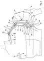
- FIG. 1 shows a motor vehicle with a total of 1 designated retractable roof, the one front section 2, a middle section 3 and a has rear section 4, which together from the shown, covering a vehicle interior 5 Closed position in an open position under storage in a convertible top compartment 6 (FIG. 7) can be transferred are.
- the components for this convertible top kinematics are each edge of the roof sections 2, 3, 4 symmetrical to Vehicle longitudinal axis arranged so that the following shown for each vehicle side and described components with opposite parts correspond.
- the motor vehicle designed according to the invention has a Roof 1, the front 2, middle 3 and rear Roof section 4 each as a rigid in itself Shell are designed using intermediate joint connectors 7, 8 are interconnected.
- FIGS. 3 to 7 with which, for example, the relocation of the roof 1 to Convertible top compartment 6 (FIG. 7) is shown, that the three roof sections 2, 3, 4 in this First open together against the direction of travel are pivotable (arrow F, Fig. 3), so that the front roof section 2 from windshield frame 10 is lifted off. Then the front roof section 2 and the middle roof section 3 each in opposite directions Regarding the rear roof section 4 with a synchronous rolling movement (arrow directions 11 and 12) Inside 13 of the rear roof section 4 down relocatable, which in turn in an arrow direction S to Convertible top compartment 6 swings out. When a final position is reached this roll-in movement is therefore all three Roof sections 2, 3, 4 in the packing position according to FIG. 7 stored in the convertible top compartment 6.
- the linkage unit 16 with an articulation point 17 ′ on the main bearing 14 forming pivot leg 17 and a drive lever 18th provided, in the area of a body-supported Drive member 19 to initiate positive control is provided.
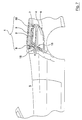
- the top compartment 6 is with provided a cover part 32, which after insertion into the Packing position above the middle roof section 3 den Convertible top compartment 6 closes (Fig. 7).
Description
Die Erfindung betrifft ein Kraftfahrzeug mit einem versenkbaren
Dach gemäß dem Oberbegriff des Anspruchs 1, das in ein vorderes,
ein mittleres und ein rückwärtiges Teilstück unterteilt
ist.The invention relates to a motor vehicle with a retractable
Roof according to the preamble of
Bei einem bekannten Kraftfahrzeug dieser Art (gemäß DE-C-874 860) ist ein dreiteiliges Verdeck vorgesehen, dessen vorderes, mittleres und rückwärtiges Dach-Teilstück jeweils als starre Schale ausgebildet ist. Nach Entriegelung einer jeweiligen Sperre wird das vordere Teilstück von Hand unter das mittlere Verdeckteil und danach diese beiden Teile unter das rückwärtige Teilstück verlagert. In dieser Packstellung ist eine 180°-Schwenkbewegung um ein am rückwärtigen Teilstück vorgesehenes Versteifungsrohr auszuführen und die Teile werden in einem heckseitigen Kofferraum eingeklappt.In a known motor vehicle of this type (according to DE-C-874 860) a three-part hood is provided, the front, middle and rear roof section each as rigid Shell is formed. After unlocking a respective one The front section is locked under the middle by hand Convertible top part and then these two parts under the rear Part relocated. In this packing position there is a 180 ° swivel movement around one provided at the rear section Stiffening pipe run and the parts are in one rear trunk folded.
Ein gemäß BE-A-368 499 bekanntes Kraftfahrzeug weist vier, jeweils als eine starre Schale ausgebildete Dach-Teilstücke auf. Bei einem von Hand schwierig und zeitaufwendig auszuführenden Öffnungsvorgang sind, ausgehend vom vorderen Schalenteil, einzelne Klappbewegungen um Scharniere auszuführen und danach können die ineinandergeklappten Teile gemeinsam zur Ablage oberhalb eines bzw. in einem heckseitigen Verdeckkasten gebracht werden, der für eine geschützte Ablage mit einem zusätzlichen Deckelteil zu verschließen ist. A motor vehicle known according to BE-A-368 499 has four, each roof sections formed as a rigid shell. For a difficult and time-consuming to perform by hand Starting from the front shell part, the opening process is individual Folding movements to perform hinges and then the folded parts together for storage above one or brought in a rear-side convertible top compartment for a protected filing with an additional Cover part to be closed.
Der Erfindung liegt die Aufgabe zugrunde, ein Kraftfahrzeug der eingangs genannten Art so auszubilden, daß das auch für ein viersitziges Fahrzeug geeignete dreiteilige Dach mit konstruktiv einfachen Mitteln automatisch in einem engen Bewegungsraum steuerbar ist, die Anwendung einer fest eingebauten Heckscheibe erleichtert und in Öffnungsstellung eine raumsparende Ablage im Verdeckkasten ermöglicht.The invention has for its object a motor vehicle of the type mentioned in such a way that the also suitable for a four-seat vehicle Roof automatically in with structurally simple means a tight range of motion is controllable, the application a fixed rear window facilitates and in the open position space-saving storage in the top compartment allows.
Die Erfindung löst diese Aufgabe mit einer Dachkonstruktion
mit den Merkmalen des Anspruchs 1. Hinsichtlich wesentlicher
weiterer Ausgestaltungsmerkmale wird auf die
Ansprüche 2 bis 7 verwiesen.The invention solves this problem with a roof structure
with the features of
Das erfindungsgemäß ausgebildete Kraftfahrzeug weist eine dreiteilige, insgesamt starre Dachkonstruktion auf, deren Dach-Teilstücke bei Verlagerung in Öffnungsstellung zum Verdeckkasten hin auf einer engen Bewegungsbahn zwangsgesteuert so verschwenkt werden können, daß das insbesondere eine feste Heckscheibe aufweisende rückwärtige Dach-Teilstück lediglich eine kreisbogenförmige Schwenkbewegung um einen karosserieseitig am Fahrzeugheckbereich befindlichen Lagerpunkt ausführt und dabei gleichzeitig die beiden vorderen Dach-Teilstücke mit einer entgegen der Fahrtrichtung verlaufenden Bewegung zur Konturinnenseite des rückwärtigen Dach-Teilstückes hin eingeschwenkt werden. Dabei wird das vordere Dach-Teilstück zwischen das obenliegende mittlere Teilstück und das rückwärtige Dach-Teilstück nach Art eines Einrollvorganges so bewegt, daß mit der danach erreichten Einrollage der starren Schalenteile eine insgesamt raumsparende Packstellung des Daches im Verdeckkasten möglich ist. The motor vehicle designed according to the invention has a three-part, overall rigid roof construction, whose Roof sections when moved to the open position Convertible top compartment positively controlled on a narrow movement path can be pivoted so that in particular a rear roof section having a fixed rear window just an arc-shaped swivel movement around a body-side at the rear of the vehicle Executes bearing point and at the same time the two front roof sections with one against the Movement in the direction of travel to the inside of the contour of the rear roof section swung in become. The front roof section is between the the middle section at the top and the rear section of the roof moved in the manner of a curling process so that with the roll-in position of the rigid shell parts subsequently achieved an overall space-saving packing position of the roof in the convertible top compartment is possible.
Die Steuerung dieser Öffnungs- bzw. Schließbewegung der drei starren Dach-Teilstücke erfolgt dabei über vorteilhaft wenige Gestängeteile mit einem jeweiligen randseitigen Antriebsorgan in Form eines Arbeitszylinders, so daß die Dachkonstruktion ein geringes Gewicht aufweist und die innenliegenden Gestängeteile raumsparend so angeordnet werden können, daß auch der Fahrgastinnenraum im Bereich des Daches weitgehend unbeeinflußt bleibt.The control of this opening or closing movement of the three rigid roof sections are done advantageously few parts with a respective edge Drive element in the form of a working cylinder, see above that the roof structure is lightweight and the inner rod parts arranged in a space-saving manner can be that the passenger interior in the area the roof remains largely unaffected.
Weitere Einzelheiten und Vorteile der Erfindung ergeben sich aus der nachfolgenden Beschreibung und den Zeichnungen, die ein Ausführungsbeispiel des erfindungsgemäßen Kraftfahrzeugs mit versenkbarem Dach veranschaulichen. In der Zeichnung zeigen:
- Fig. 1
- eine Seitenansicht eines Kraftfahrzeugs mit einem drei Dach-Teilstücke aufweisenden Dach in Schließstellung,
- Fig. 2
- eine teilweise geschnittene Seitenansicht des Kraftfahrzeugs gemäß Fig. 1 mit der erfindungsgemäßen Verdeckkinematik,
- Fig. 3 bis 6
- jeweilige Ausschnittsdarstellungen des Kraftfahrzeugs mit den Dach-Teilstücken in unterschiedlichen Bewegungsphasen bei einem Öffnungsvorgang, und
- Fig. 7
- eine Ausschnittsdarstellung mit den drei Dachteilen in Ablagestellung in einem Verdeckkasten.
- Fig. 1
- 2 shows a side view of a motor vehicle with a roof having three roof sections in the closed position,
- Fig. 2
- 2 shows a partially sectioned side view of the motor vehicle according to FIG. 1 with the convertible top kinematics according to the invention,
- 3 to 6
- respective cutouts of the motor vehicle with the roof sections in different phases of movement during an opening process, and
- Fig. 7
- a sectional view with the three roof parts in the storage position in a convertible top compartment.
In Fig. 1 ist ein Kraftfahrzeug mit einem insgesamt mit 1
bezeichneten versenkbaren Dach dargestellt, das ein
vorderes Teilstück 2, ein mittleres Teilstück 3 und ein
rückwärtiges Teilstück 4 aufweist, die gemeinsam aus der
dargestellten, einen Fahrzeuginnenraum 5 überdeckenden
Schließstellung in eine Öffnungsstellung unter Ablage in
einem heckseitigen Verdeckkasten 6 (Fig. 7) überführbar
sind. Die Bauteile für diese Verdeckkinematik sind jeweils
randseitig an den Dach-Teilstücken 2, 3, 4 symmetrisch zur
Fahrzeuglängsachse angeordnet, so daß damit die nachfolgend
für jeweils eine Fahrzeugseite dargestellten und
beschriebenen Bauteile mit gegenüberliegenden Teilen
korrespondieren.1 shows a motor vehicle with a total of 1
designated retractable roof, the one
Das erfindungsgemäß ausgebildete Kraftfahrzeug weist ein
Dach 1 auf, dessen vorderes 2, mittleres 3 und rückwärtiges
Dach-Teilstück 4 jeweils als eine an sich starre
Schale ausgeführt sind, die über zwischenliegende Gelenkverbinder
7, 8 miteinander verbunden sind.The motor vehicle designed according to the invention has a
Die unterschiedlichen Bewegungsphasen gemäß Fig. 3 bis 7,
mit denen beispielhaft die Verlagerung des Daches 1 zum
Verdeckkasten 6 (Fig. 7) hin dargestellt ist, verdeutlichen,
daß die drei Dach-Teilstücke 2, 3, 4 bei diesem
Öffnungsvorgang zunächst gemeinsam entgegen der Fahrtrichtung
verschwenkbar sind (Pfeil F, Fig. 3), so daß das
vordere Dach-Teilstück 2 vom Windschutzscheibenrahmen 10
abgehoben wird. Danach sind das vordere Dach-Teilstück 2
und das mittlere Dach-Teilstück 3 jeweils gegensinnig in
Bezug auf das rückwärtige Dach-Teilstück 4 mit einer
synchronen Einrollbewegung (Pfeilrichtungen 11 und 12) zur
Innenseite 13 des rückwärtigen Dach-Teilstückes 4 hin
verlagerbar, das seinerseits in einer Pfeilrichtung S zum
Verdeckkasten 6 hin schwenkt. Mit dem Erreichen einer Endstellung
dieser Einrollbewegung sind sonach alle drei
Dach-Teilstücke 2, 3, 4 in der Packstellung gemäß Fig. 7
im Verdeckkasten 6 abgelegt.The different movement phases according to FIGS. 3 to 7,
with which, for example, the relocation of the
Für eine automatische, zwangsgesteuerte Ausführung des
vorbeschriebenen Öffnungsvorganges (der sich in umgekehrter
Bewegungsabfolge beim Schließvorgang des Daches 1
wiederholt) ist das rückwärtige Dach-Teilstück 4 im Bereich
eines karosserieseitigen Hauptlagers 14 sowohl über
einen Schwenkansatz 15 als auch eine in dessen Nahbereich
vorgesehene zweiteilige Gestängeeinheit 16 abgestützt,
wobei diese anderenends im Bereich des ersten Gelenkverbinders
7 an das mittlere Dach-Teilstück 3 gekoppelt ist.For an automatic, positively controlled execution of the
opening process described above (which takes place in reverse
Sequence of movements when closing the
In der dargestellten Ausführungsform ist die Gestängeeinheit
16 mit einem einen Gelenkpunkt 17' am Hauptlager 14
bildenden Schwenkschenkel 17 und einem Antriebshebel 18
versehen, in deren Bereich ein karosserieseitig abgestütztes
Antriebsorgan 19 zur Einleitung der Zwangssteuerung
vorgesehen ist. In zweckmäßiger Ausführung ist das
Antriebsorgan 19 von einem Hydraulikzylinder 20 gebildet
dessen Kolbenstange 21 in einem Verbindungsgelenk 22 an
der Gestängeeinheit 16 angreift.In the illustrated embodiment, the
Mit dieser Antriebskinematik erfolgt der phasenweise dargestellte
Öffnungsvorgang, wobei der Antriebshebel 18 bei
Einleitung des Öffnungsvorganges (Fig. 3) mittels einer
Zugbewegung des Hydraulikzylinders 20 (Pfeil 23; Schwenkstellung
Z in Fig. 4) eine vom Schwenkhebel 17 gesteuerte,
kreisbogenförmige Bahnkurve durchläuft, das rückwärtige
Dach-Teilstück 4 eine dazu synchrone Schwenkbewegung
ausführt (Pfeil S) und gleichzeitig die beiden vorderen
Dach-Teilstücke 2, 3 mittels des Antriebshebels 18 im
Bereich ihrer Gelenkverbinder 7, 8 so gesteuert werden,
daß die vorbeschriebene Einrollbewegung (Pfeile 11, 12)
zur Innenseite 13 des rückwärtigen Dach-Teilstückes 4 hin
erfolgt.With this drive kinematics, it is shown in phases
Opening process, the
Nach Erreichen einer ersten Bewegungsstellung Z' gemäß
Fig. 5 (die Dachteile sind oberhalb des Verdeckkastens 6
positioniert) erfolgt eine Umsteuerung der Arbeitsrichtung
des Hydraulikzylinders 20 (Pfeil 23', Fig. 6) und bis zum
Erreichen der Packstellung wird nunmehr das vordere Dach-Teilstück
2 zwischen die weiter einrollenden Dach-Teilstücke
3 und 4 eingelegt (Stellung Z'', Fig. 6).After reaching a first movement position Z 'according to
Fig. 5 (the roof parts are above the
Für diesen Bewegungsvorgang des Daches 1 ist der Antriebshebel
18 im Bereich des ersten Gelenkverbinders 7 an einem
einen Gelenkpunkt 24 bildenden Schwenkhebel 25 mit Ansatzteilen
angelenkt, mittels der über einen Zwischenhebel
26 eine gelenkige Verbindung zu einer zum zweiten
Gelenkverbinder 8 gerichteten Schwingstange 27 geschaffen
ist. Die Schwingstange 27 greift ihrerseits über einen
Winkelhebel 28 mit Ansatzteilen gelenkig am vorderen Dach-Teilstück
2 an, so daß mit diesen Gelenkverbindern 7, 8
eine konstruktiv einfache und störrunanfällige Antriebseinheit
für das Dach 1 geschaffen ist, die eine zuverlässige
Steuerung des Daches 1 auch bei einem viersitzigen
Fahrzeug ermöglicht.For this movement process of the
Zur Stabilisierung der Dachteile 2, 3, 4 in ihrer gemeinsamen
Schließstellung (Fig. 1) sind im Bereich der Gelenkverbinder
7, 8 jeweilige Rastverbinder 30, 31 vorgesehen,
die in zweckmäßiger Ausführung über die Hebelbauteile im
Bereich der Gelenkverbinder steuerbar sind.To stabilize the
In zweckmäßiger Ausführung ist der Verdeckkasten 6 mit
einem Deckelteil 32 versehen, das nach dem Einlegen in die
Packstellung oberhalb des mittleren Dach-Teilstückes 3 den
Verdeckkasten 6 verschließt (Fig. 7).In a practical embodiment, the
Claims (7)
- Motor Vehicle with a roof (1) capable of being retracted which is divided into a front- (2), central- (3) and a rear element (4) which may be converted from a common closed position situated above the interior of the motor vehicle (5) into an open position by lowering it into a rear-located roof-compartment (6) whereby the front (2), central (3) and rear roof element (4) have the form of a rigid panel and are connected together by linkage assemblies (7, 8)
characterised in that the rear element (4) is supported by a framework member (16) in a manner allowing it to rotate about a main bearing (14) attached to the coachwork where an actuating element (19) attached to the main bearing engages with the framework member (16) and where the three roof-elements, (2, 3, 4) are constrained to move in such a manner that when in the open position the front roof-element (2) is swept in an opposing direction under the central roof-element (3) and that both, when packed together with the swung-back rear roof-element (4) form a covering for the roof compartment (6). - Motor vehicle in accordance with claim 1, characterised in that the central roof-element (3) and the front roof-element (2) are respectively capable of being supported in the area of the appropriate linkage assembly (7, 8) and of being folded in a reverse direction while for its part the rear roof-element (4) in the area of the main bearing (14) attached to the coachwork is supported by a pivoting projection (15) close to which one end of a two-component framework element (16) is carried in a bearing and the other end engages in the area of the first linkage assembly (7).
- Motor vehicle in accordance with claims 1 or 2, characterised in that the roof (1) in the area of the frame member (16) exhibiting a pivoting element (17) and an actuating lever (18) is provided with an actuating device (19) attached to the coachwork.
- Motor vehicle in accordance with one of the claims 1 to 3, characterised in that a hydraulic cylinder (20) is provided as the actuating device (19), the piston rod (21) of which engages with a connecting linkage (22) joining the pivoting element (17) and the actuating lever (18) to the framework element (16).
- Motor vehicle in accordance with one of the claims 1 to 4 characterised in that when the opening sequence is initiated by a pulling action from the hydraulic cylinder (20) the actuating end of the actuating lever (18) moves through an arc-shaped curve controlled by the pivoting element (17) and the three roof-elements (2, 3, 4) are capable of being re-assembled into a first roll-up position above the roof compartment (6) and subsequently, as a result of a reverse movement by the hydraulic cylinder (20), the rear roof-element (4) can be swung under the front (2) and the central (3) roof element into the packed position in a compact arrangement.
- Motor vehicle in accordance with one of the claims 1 to 5 characterised in that in the area of the first linkage assembly (7) the actuating lever (18) engages with a swivelling lever (25) forming a linkage point (24), which for its part is articulated via an intermediate lever (26) with a swivelling bar (27) directed towards a second linkage assembly (8) and which engages via an angle-lever (28) with the front roof-element (2).
- Motor vehicle in accordance with one of the claims 1 to 6, characterised in that a snap-in locking device (30, 31) is provided in each of the linkage assembly areas (7, 8).
Applications Claiming Priority (2)
| Application Number | Priority Date | Filing Date | Title |
|---|---|---|---|
| DE19642153 | 1996-10-12 | ||
| DE19642153A DE19642153A1 (en) | 1996-10-12 | 1996-10-12 | Motor vehicle with a retractable roof |
Publications (2)
| Publication Number | Publication Date |
|---|---|
| EP0835779A1 EP0835779A1 (en) | 1998-04-15 |
| EP0835779B1 true EP0835779B1 (en) | 2002-10-16 |
Family
ID=7808586
Family Applications (1)
| Application Number | Title | Priority Date | Filing Date |
|---|---|---|---|
| EP97114142A Expired - Lifetime EP0835779B1 (en) | 1996-10-12 | 1997-08-16 | Retractable roof for vehicle |
Country Status (2)
| Country | Link |
|---|---|
| EP (1) | EP0835779B1 (en) |
| DE (2) | DE19642153A1 (en) |
Cited By (2)
| Publication number | Priority date | Publication date | Assignee | Title |
|---|---|---|---|---|
| US6964340B2 (en) | 2003-04-18 | 2005-11-15 | Wilhelm Karmann Gmbh | Retractable hardtop with articulating center panel |
| DE102005060459B4 (en) * | 2005-12-17 | 2012-05-10 | Magna Car Top Systems Gmbh | Washer for adjacent limbs |
Families Citing this family (24)
| Publication number | Priority date | Publication date | Assignee | Title |
|---|---|---|---|---|
| DE19820338B4 (en) * | 1998-05-07 | 2005-07-28 | Daimlerchrysler Ag | motor vehicle |
| DE19847983C1 (en) * | 1998-10-17 | 2000-05-25 | Daimler Chrysler Ag | Multi-part, retractable vehicle top |
| DE19904661C1 (en) * | 1999-02-04 | 2000-07-20 | Janusz Tchorzewski | Folding roof assembly for a convertible automobile has openings in the two roof sections so that the luggage compartment can be accessed and loaded when the roof is open and still carry large items |
| DE19934673C1 (en) * | 1999-07-23 | 2001-01-25 | Daimler Chrysler Ag | Hardtop roof for cabriolet automobile has front, centre and rear roof sections coupled together via lever mechanism for stacking roof sections on top of one another in open position |
| US6478362B2 (en) | 1999-12-22 | 2002-11-12 | Ed. Scharwaechter Gmbh | Convertible top and driving device for a convertible top |
| FR2815581B1 (en) * | 2000-10-23 | 2003-02-07 | France Design | RETRACTABLE ROOF FOR VEHICLE, COMPRISING TWO LONGITUDINAL ELEMENTS |
| FR2816254B1 (en) * | 2000-11-06 | 2003-02-07 | France Design | RETRACTABLE ROOF FOR VEHICLE WITH TWO PIVOTING ARMS |
| DE10111207A1 (en) | 2001-03-08 | 2002-09-19 | Valmet Automotive Oy Uusikaupu | Convertible top |
| DE10137465C2 (en) | 2001-08-02 | 2003-05-28 | Cts Fahrzeug Dachsysteme Gmbh | Hardtop vehicle roof with at least two rigid roof parts |
| US6666495B2 (en) * | 2001-09-13 | 2003-12-23 | Edscha Roof Systems Inc. | Retractable top system for vehicles with movable rear section |
| DE10147015C2 (en) * | 2001-09-25 | 2003-08-07 | Cts Fahrzeug Dachsysteme Gmbh | Multi-part hardtop vehicle roof |
| DE10149456A1 (en) * | 2001-10-08 | 2003-04-30 | Cts Fahrzeug Dachsysteme Gmbh | Hardtop vehicle roof with at least two rigid roof parts |
| DE10151170A1 (en) * | 2001-10-19 | 2003-05-08 | Cts Fahrzeug Dachsysteme Gmbh | Hardtop vehicle roof with three rigid roof parts |
| DE10391497D2 (en) | 2002-04-12 | 2005-05-19 | Edscha Cabrio Dachsys Gmbh | Hood for a convertible vehicle |
| FI20021236A0 (en) * | 2002-06-24 | 2002-06-24 | Valmet Automotive Oy | Openable hardtop for convertible and convertible |
| DE10240567C5 (en) * | 2002-08-29 | 2010-10-14 | Magna Car Top Systems Gmbh | Hardtop vehicle roof with at least two rigid roof parts |
| DE50302408D1 (en) | 2002-09-16 | 2006-04-20 | Edscha Cabrio Dachsys Gmbh | Hood for a convertible vehicle |
| DE10329439A1 (en) | 2003-07-01 | 2005-01-27 | Daimlerchrysler Ag | Cabriolet vehicle with a hardtop |
| DE10345751A1 (en) * | 2003-10-01 | 2005-05-04 | Daimler Chrysler Ag | Hardtop for a convertible vehicle |
| FR2877274B1 (en) * | 2004-11-02 | 2010-03-05 | France Design | VEHICLE WITH FOLDABLE ROOFABLE LATCH |
| FR2877275B1 (en) * | 2004-11-02 | 2010-03-19 | France Design | VEHICLE WITH FOLDABLE ROOFABLE LATCH |
| DE102005004018A1 (en) * | 2005-01-28 | 2006-08-03 | Wilhelm Karmann Gmbh | Roof system for vehicles has at least three parts connected through kinematic devices so that with roof fully open the first part is positioned in storage area between second and third parts |
| DE102005062193A1 (en) * | 2005-12-23 | 2007-08-16 | Wilhelm Karmann Gmbh | Convertible vehicle with at least three consecutive roof sections |
| FR2963284B1 (en) * | 2010-07-27 | 2014-01-24 | Peugeot Citroen Automobiles Sa | MOTOR VEHICLE EQUIPPED WITH A RETRACTABLE ROOF. |
Family Cites Families (7)
| Publication number | Priority date | Publication date | Assignee | Title |
|---|---|---|---|---|
| BE368499A (en) * | ||||
| FR733380A (en) * | 1931-06-02 | 1932-10-05 | Auto-displacement retractable hood, for motor vehicles | |
| DE3635373A1 (en) * | 1986-10-17 | 1988-04-21 | Autoschmiede Meier Menge Gmbh | Folding roof for motor vehicles |
| DE9307481U1 (en) * | 1993-05-17 | 1993-07-15 | Ed. Scharwaechter Gmbh + Co Fahrzeugtechnik, 8355 Hengersberg, De | |
| DE4435222C1 (en) * | 1994-09-30 | 1995-11-02 | Webasto Karosseriesysteme | Roof for convertible car |
| DE4438925C1 (en) * | 1994-10-31 | 1995-11-09 | Porsche Ag | Folding roof for motor vehicle |
| DE19520648C2 (en) * | 1995-06-09 | 2002-11-07 | Scharwaechter Gmbh Co Kg | Movable roof for motor vehicles |
-
1996
- 1996-10-12 DE DE19642153A patent/DE19642153A1/en not_active Ceased
-
1997
- 1997-08-16 DE DE59708483T patent/DE59708483D1/en not_active Expired - Lifetime
- 1997-08-16 EP EP97114142A patent/EP0835779B1/en not_active Expired - Lifetime
Cited By (3)
| Publication number | Priority date | Publication date | Assignee | Title |
|---|---|---|---|---|
| US6964340B2 (en) | 2003-04-18 | 2005-11-15 | Wilhelm Karmann Gmbh | Retractable hardtop with articulating center panel |
| US7182390B2 (en) | 2003-04-18 | 2007-02-27 | Wilhelm Karmann Gmbh | Retractable hardtop with articulating center panel |
| DE102005060459B4 (en) * | 2005-12-17 | 2012-05-10 | Magna Car Top Systems Gmbh | Washer for adjacent limbs |
Also Published As
| Publication number | Publication date |
|---|---|
| EP0835779A1 (en) | 1998-04-15 |
| DE59708483D1 (en) | 2002-11-21 |
| DE19642153A1 (en) | 1998-04-16 |
Similar Documents
| Publication | Publication Date | Title |
|---|---|---|
| EP0835779B1 (en) | Retractable roof for vehicle | |
| EP0835780B1 (en) | Retractable roof for vehicle | |
| DE10063152B4 (en) | Folding roof cars | |
| EP0835778B1 (en) | Vehicle with retractable roof | |
| EP1092579B1 (en) | Retractable folding top for motor vehicle and vehicle provided with this folding top | |
| DE19634507C1 (en) | Roof for convertible sports car | |
| DE4445580C1 (en) | Hard=top vehicle roof linkage | |
| DE10019366C2 (en) | Roof construction for a motor vehicle with a removable roof | |
| EP0521307B2 (en) | Folding hood for motorvehicle provided with a collapsible roof | |
| DE10116709C2 (en) | Folding top with rear window control | |
| EP0826537B1 (en) | Vehicle roof construction,especially for passenger motor vehicle | |
| DE10028405B4 (en) | Boot lid assembly for a vehicle with a retractable top | |
| DE4316485A1 (en) | Folding top for motor vehicles | |
| DE19623036A1 (en) | Vehicle, in particular with a retractable roof | |
| DE10134370A1 (en) | Covering device for a convertible top compartment | |
| DE10050286A1 (en) | Multi-part cover for vehicles | |
| EP1831043B1 (en) | Cabriolet vehicle having a movable rear-window shelf | |
| DE19939954B4 (en) | Faltschiebedachanordnung | |
| EP1562768B1 (en) | Hood for a convertible | |
| DE19704570C2 (en) | Car with an openable roof | |
| EP0974480B1 (en) | Folding top system for motor vehicle | |
| EP1893433B1 (en) | Convertible with a roof which can be stored below a covering | |
| WO2003095254A1 (en) | Cabriolet vehicle comprising a rear storage compartment for the top thereof | |
| DE10039220A1 (en) | Adjustable vehicle roof has at least two rod parts connected to each other by prismatic joint | |
| DE10137048A1 (en) | Car with openable folding roof |
Legal Events
| Date | Code | Title | Description |
|---|---|---|---|
| PUAI | Public reference made under article 153(3) epc to a published international application that has entered the european phase |
Free format text: ORIGINAL CODE: 0009012 |
|
| AK | Designated contracting states |
Kind code of ref document: A1 Designated state(s): DE FI FR GB IT SE |
|
| AX | Request for extension of the european patent |
Free format text: AL;LT;LV;RO;SI |
|
| 17P | Request for examination filed |
Effective date: 19980402 |
|
| AKX | Designation fees paid |
Free format text: DE FI FR GB IT SE |
|
| RBV | Designated contracting states (corrected) |
Designated state(s): DE FI FR GB IT SE |
|
| 17Q | First examination report despatched |
Effective date: 19990705 |
|
| GRAG | Despatch of communication of intention to grant |
Free format text: ORIGINAL CODE: EPIDOS AGRA |
|
| GRAG | Despatch of communication of intention to grant |
Free format text: ORIGINAL CODE: EPIDOS AGRA |
|
| GRAH | Despatch of communication of intention to grant a patent |
Free format text: ORIGINAL CODE: EPIDOS IGRA |
|
| GRAH | Despatch of communication of intention to grant a patent |
Free format text: ORIGINAL CODE: EPIDOS IGRA |
|
| TPAD | Observations filed by third parties |
Free format text: ORIGINAL CODE: EPIDOS TIPA |
|
| GRAG | Despatch of communication of intention to grant |
Free format text: ORIGINAL CODE: EPIDOS AGRA |
|
| GRAG | Despatch of communication of intention to grant |
Free format text: ORIGINAL CODE: EPIDOS AGRA |
|
| GRAH | Despatch of communication of intention to grant a patent |
Free format text: ORIGINAL CODE: EPIDOS IGRA |
|
| GRAA | (expected) grant |
Free format text: ORIGINAL CODE: 0009210 |
|
| AK | Designated contracting states |
Kind code of ref document: B1 Designated state(s): DE FI FR GB IT SE |
|
| PG25 | Lapsed in a contracting state [announced via postgrant information from national office to epo] |
Ref country code: FI Free format text: LAPSE BECAUSE OF FAILURE TO SUBMIT A TRANSLATION OF THE DESCRIPTION OR TO PAY THE FEE WITHIN THE PRESCRIBED TIME-LIMIT Effective date: 20021016 |
|
| REG | Reference to a national code |
Ref country code: GB Ref legal event code: FG4D Free format text: NOT ENGLISH |
|
| REF | Corresponds to: |
Ref document number: 59708483 Country of ref document: DE Date of ref document: 20021121 |
|
| GBT | Gb: translation of ep patent filed (gb section 77(6)(a)/1977) |
Effective date: 20021129 |
|
| PG25 | Lapsed in a contracting state [announced via postgrant information from national office to epo] |
Ref country code: SE Free format text: LAPSE BECAUSE OF FAILURE TO SUBMIT A TRANSLATION OF THE DESCRIPTION OR TO PAY THE FEE WITHIN THE PRESCRIBED TIME-LIMIT Effective date: 20030116 |
|
| ET | Fr: translation filed | ||
| PLBE | No opposition filed within time limit |
Free format text: ORIGINAL CODE: 0009261 |
|
| STAA | Information on the status of an ep patent application or granted ep patent |
Free format text: STATUS: NO OPPOSITION FILED WITHIN TIME LIMIT |
|
| 26N | No opposition filed |
Effective date: 20030717 |
|
| REG | Reference to a national code |
Ref country code: GB Ref legal event code: 732E Free format text: REGISTERED BETWEEN 20101014 AND 20101020 |
|
| PGFP | Annual fee paid to national office [announced via postgrant information from national office to epo] |
Ref country code: IT Payment date: 20100818 Year of fee payment: 14 |
|
| REG | Reference to a national code |
Ref country code: FR Ref legal event code: TP |
|
| REG | Reference to a national code |
Ref country code: DE Ref legal event code: R081 Ref document number: 59708483 Country of ref document: DE Owner name: VALMET AUTOMOTIVE OY, FI Free format text: FORMER OWNERS: WILHELM KARMANN GMBH, 49084 OSNABRUECK, DE; BAYERISCHE MOTOREN WERKE AKTIENGESELLSCHAFT, 80809 MUENCHEN, DE Effective date: 20110209 Ref country code: DE Ref legal event code: R081 Ref document number: 59708483 Country of ref document: DE Owner name: VALMET AUTOMOTIVE OY, FI Free format text: FORMER OWNER: WILHELM KARMANN GMBH, BAYERISCHE MOTOREN WERKE AKTIEN, , DE Effective date: 20110209 |
|
| PG25 | Lapsed in a contracting state [announced via postgrant information from national office to epo] |
Ref country code: IT Free format text: LAPSE BECAUSE OF NON-PAYMENT OF DUE FEES Effective date: 20110816 |
|
| PGFP | Annual fee paid to national office [announced via postgrant information from national office to epo] |
Ref country code: GB Payment date: 20120823 Year of fee payment: 16 |
|
| PGFP | Annual fee paid to national office [announced via postgrant information from national office to epo] |
Ref country code: FR Payment date: 20120831 Year of fee payment: 16 |
|
| PGFP | Annual fee paid to national office [announced via postgrant information from national office to epo] |
Ref country code: DE Payment date: 20121024 Year of fee payment: 16 |
|
| REG | Reference to a national code |
Ref country code: GB Ref legal event code: 732E Free format text: REGISTERED BETWEEN 20131114 AND 20131120 |
|
| REG | Reference to a national code |
Ref country code: FR Ref legal event code: TP Owner name: VALMET AUTOMOTIVE OY, FI Effective date: 20131209 |
|
| REG | Reference to a national code |
Ref country code: DE Ref legal event code: R082 Ref document number: 59708483 Country of ref document: DE Representative=s name: KRONTHALER, SCHMIDT & COLL. PATENTANWALTSKANZL, DE Effective date: 20131128 Ref country code: DE Ref legal event code: R081 Ref document number: 59708483 Country of ref document: DE Owner name: VALMET AUTOMOTIVE OY, FI Free format text: FORMER OWNER: WILHELM KARMANN GMBH, 49084 OSNABRUECK, DE Effective date: 20131128 |
|
| GBPC | Gb: european patent ceased through non-payment of renewal fee |
Effective date: 20130816 |
|
| PG25 | Lapsed in a contracting state [announced via postgrant information from national office to epo] |
Ref country code: DE Free format text: LAPSE BECAUSE OF NON-PAYMENT OF DUE FEES Effective date: 20140301 |
|
| REG | Reference to a national code |
Ref country code: DE Ref legal event code: R119 Ref document number: 59708483 Country of ref document: DE Effective date: 20140301 |
|
| REG | Reference to a national code |
Ref country code: FR Ref legal event code: ST Effective date: 20140430 |
|
| PG25 | Lapsed in a contracting state [announced via postgrant information from national office to epo] |
Ref country code: GB Free format text: LAPSE BECAUSE OF NON-PAYMENT OF DUE FEES Effective date: 20130816 |
|
| PG25 | Lapsed in a contracting state [announced via postgrant information from national office to epo] |
Ref country code: FR Free format text: LAPSE BECAUSE OF NON-PAYMENT OF DUE FEES Effective date: 20130902 |