EP0839655B1 - Multi-layer ink jet recording head - Google Patents
Multi-layer ink jet recording head Download PDFInfo
- Publication number
- EP0839655B1 EP0839655B1 EP98102295A EP98102295A EP0839655B1 EP 0839655 B1 EP0839655 B1 EP 0839655B1 EP 98102295 A EP98102295 A EP 98102295A EP 98102295 A EP98102295 A EP 98102295A EP 0839655 B1 EP0839655 B1 EP 0839655B1
- Authority
- EP
- European Patent Office
- Prior art keywords
- holes
- ink
- recording head
- pressure chambers
- ink supplying
- Prior art date
- Legal status (The legal status is an assumption and is not a legal conclusion. Google has not performed a legal analysis and makes no representation as to the accuracy of the status listed.)
- Expired - Lifetime
Links
- 125000006850 spacer group Chemical group 0.000 claims description 37
- 238000004891 communication Methods 0.000 claims description 19
- 239000000853 adhesive Substances 0.000 claims description 15
- 239000002184 metal Substances 0.000 claims description 13
- 229910052751 metal Inorganic materials 0.000 claims description 13
- 238000005304 joining Methods 0.000 claims description 7
- MCMNRKCIXSYSNV-UHFFFAOYSA-N Zirconium dioxide Chemical compound O=[Zr]=O MCMNRKCIXSYSNV-UHFFFAOYSA-N 0.000 description 14
- 239000010410 layer Substances 0.000 description 14
- 239000000919 ceramic Substances 0.000 description 12
- 230000001070 adhesive effect Effects 0.000 description 8
- 230000015572 biosynthetic process Effects 0.000 description 7
- 239000010408 film Substances 0.000 description 7
- 238000010304 firing Methods 0.000 description 7
- 238000004519 manufacturing process Methods 0.000 description 7
- 239000012790 adhesive layer Substances 0.000 description 6
- 238000006073 displacement reaction Methods 0.000 description 6
- 239000000463 material Substances 0.000 description 6
- 238000000034 method Methods 0.000 description 6
- 238000010586 diagram Methods 0.000 description 3
- 238000003466 welding Methods 0.000 description 3
- 238000005452 bending Methods 0.000 description 2
- 238000005530 etching Methods 0.000 description 2
- 230000005499 meniscus Effects 0.000 description 2
- 238000007639 printing Methods 0.000 description 2
- 238000004544 sputter deposition Methods 0.000 description 2
- 229910001220 stainless steel Inorganic materials 0.000 description 2
- 239000010935 stainless steel Substances 0.000 description 2
- 230000002411 adverse Effects 0.000 description 1
- 230000002238 attenuated effect Effects 0.000 description 1
- 229910010293 ceramic material Inorganic materials 0.000 description 1
- 239000011248 coating agent Substances 0.000 description 1
- 238000000576 coating method Methods 0.000 description 1
- 239000004020 conductor Substances 0.000 description 1
- 238000010276 construction Methods 0.000 description 1
- 238000005260 corrosion Methods 0.000 description 1
- 230000007797 corrosion Effects 0.000 description 1
- 238000005520 cutting process Methods 0.000 description 1
- 230000003247 decreasing effect Effects 0.000 description 1
- 230000001419 dependent effect Effects 0.000 description 1
- 238000009792 diffusion process Methods 0.000 description 1
- 238000001035 drying Methods 0.000 description 1
- 239000007788 liquid Substances 0.000 description 1
- 150000002739 metals Chemical class 0.000 description 1
- 238000003825 pressing Methods 0.000 description 1
- 230000001902 propagating effect Effects 0.000 description 1
- 230000001105 regulatory effect Effects 0.000 description 1
- 239000007787 solid Substances 0.000 description 1
- 238000003892 spreading Methods 0.000 description 1
- 239000010409 thin film Substances 0.000 description 1
Images

Classifications
-
- B—PERFORMING OPERATIONS; TRANSPORTING
- B41—PRINTING; LINING MACHINES; TYPEWRITERS; STAMPS
- B41J—TYPEWRITERS; SELECTIVE PRINTING MECHANISMS, i.e. MECHANISMS PRINTING OTHERWISE THAN FROM A FORME; CORRECTION OF TYPOGRAPHICAL ERRORS
- B41J2/00—Typewriters or selective printing mechanisms characterised by the printing or marking process for which they are designed
- B41J2/005—Typewriters or selective printing mechanisms characterised by the printing or marking process for which they are designed characterised by bringing liquid or particles selectively into contact with a printing material
- B41J2/01—Ink jet
- B41J2/135—Nozzles
- B41J2/16—Production of nozzles
- B41J2/1621—Manufacturing processes
- B41J2/1623—Manufacturing processes bonding and adhesion
-
- B—PERFORMING OPERATIONS; TRANSPORTING
- B41—PRINTING; LINING MACHINES; TYPEWRITERS; STAMPS
- B41J—TYPEWRITERS; SELECTIVE PRINTING MECHANISMS, i.e. MECHANISMS PRINTING OTHERWISE THAN FROM A FORME; CORRECTION OF TYPOGRAPHICAL ERRORS
- B41J2/00—Typewriters or selective printing mechanisms characterised by the printing or marking process for which they are designed
- B41J2/005—Typewriters or selective printing mechanisms characterised by the printing or marking process for which they are designed characterised by bringing liquid or particles selectively into contact with a printing material
- B41J2/01—Ink jet
- B41J2/135—Nozzles
- B41J2/14—Structure thereof only for on-demand ink jet heads
- B41J2/14201—Structure of print heads with piezoelectric elements
- B41J2/14233—Structure of print heads with piezoelectric elements of film type, deformed by bending and disposed on a diaphragm
-
- B—PERFORMING OPERATIONS; TRANSPORTING
- B41—PRINTING; LINING MACHINES; TYPEWRITERS; STAMPS
- B41J—TYPEWRITERS; SELECTIVE PRINTING MECHANISMS, i.e. MECHANISMS PRINTING OTHERWISE THAN FROM A FORME; CORRECTION OF TYPOGRAPHICAL ERRORS
- B41J2/00—Typewriters or selective printing mechanisms characterised by the printing or marking process for which they are designed
- B41J2/005—Typewriters or selective printing mechanisms characterised by the printing or marking process for which they are designed characterised by bringing liquid or particles selectively into contact with a printing material
- B41J2/01—Ink jet
- B41J2/135—Nozzles
- B41J2/16—Production of nozzles
- B41J2/1607—Production of print heads with piezoelectric elements
- B41J2/161—Production of print heads with piezoelectric elements of film type, deformed by bending and disposed on a diaphragm
-
- B—PERFORMING OPERATIONS; TRANSPORTING
- B41—PRINTING; LINING MACHINES; TYPEWRITERS; STAMPS
- B41J—TYPEWRITERS; SELECTIVE PRINTING MECHANISMS, i.e. MECHANISMS PRINTING OTHERWISE THAN FROM A FORME; CORRECTION OF TYPOGRAPHICAL ERRORS
- B41J2/00—Typewriters or selective printing mechanisms characterised by the printing or marking process for which they are designed
- B41J2/005—Typewriters or selective printing mechanisms characterised by the printing or marking process for which they are designed characterised by bringing liquid or particles selectively into contact with a printing material
- B41J2/01—Ink jet
- B41J2/135—Nozzles
- B41J2/16—Production of nozzles
- B41J2/1621—Manufacturing processes
- B41J2/1632—Manufacturing processes machining
-
- B—PERFORMING OPERATIONS; TRANSPORTING
- B41—PRINTING; LINING MACHINES; TYPEWRITERS; STAMPS
- B41J—TYPEWRITERS; SELECTIVE PRINTING MECHANISMS, i.e. MECHANISMS PRINTING OTHERWISE THAN FROM A FORME; CORRECTION OF TYPOGRAPHICAL ERRORS
- B41J2/00—Typewriters or selective printing mechanisms characterised by the printing or marking process for which they are designed
- B41J2/005—Typewriters or selective printing mechanisms characterised by the printing or marking process for which they are designed characterised by bringing liquid or particles selectively into contact with a printing material
- B41J2/01—Ink jet
- B41J2/135—Nozzles
- B41J2/16—Production of nozzles
- B41J2/1621—Manufacturing processes
- B41J2/164—Manufacturing processes thin film formation
- B41J2/1642—Manufacturing processes thin film formation thin film formation by CVD [chemical vapor deposition]
-
- B—PERFORMING OPERATIONS; TRANSPORTING
- B41—PRINTING; LINING MACHINES; TYPEWRITERS; STAMPS
- B41J—TYPEWRITERS; SELECTIVE PRINTING MECHANISMS, i.e. MECHANISMS PRINTING OTHERWISE THAN FROM A FORME; CORRECTION OF TYPOGRAPHICAL ERRORS
- B41J2/00—Typewriters or selective printing mechanisms characterised by the printing or marking process for which they are designed
- B41J2/005—Typewriters or selective printing mechanisms characterised by the printing or marking process for which they are designed characterised by bringing liquid or particles selectively into contact with a printing material
- B41J2/01—Ink jet
- B41J2/135—Nozzles
- B41J2/16—Production of nozzles
- B41J2/1621—Manufacturing processes
- B41J2/164—Manufacturing processes thin film formation
- B41J2/1643—Manufacturing processes thin film formation thin film formation by plating
-
- B—PERFORMING OPERATIONS; TRANSPORTING
- B41—PRINTING; LINING MACHINES; TYPEWRITERS; STAMPS
- B41J—TYPEWRITERS; SELECTIVE PRINTING MECHANISMS, i.e. MECHANISMS PRINTING OTHERWISE THAN FROM A FORME; CORRECTION OF TYPOGRAPHICAL ERRORS
- B41J2/00—Typewriters or selective printing mechanisms characterised by the printing or marking process for which they are designed
- B41J2/005—Typewriters or selective printing mechanisms characterised by the printing or marking process for which they are designed characterised by bringing liquid or particles selectively into contact with a printing material
- B41J2/01—Ink jet
- B41J2/135—Nozzles
- B41J2/16—Production of nozzles
- B41J2/1621—Manufacturing processes
- B41J2/164—Manufacturing processes thin film formation
- B41J2/1646—Manufacturing processes thin film formation thin film formation by sputtering
-
- H—ELECTRICITY
- H10—SEMICONDUCTOR DEVICES; ELECTRIC SOLID-STATE DEVICES NOT OTHERWISE PROVIDED FOR
- H10N—ELECTRIC SOLID-STATE DEVICES NOT OTHERWISE PROVIDED FOR
- H10N30/00—Piezoelectric or electrostrictive devices
- H10N30/20—Piezoelectric or electrostrictive devices with electrical input and mechanical output, e.g. functioning as actuators or vibrators
- H10N30/204—Piezoelectric or electrostrictive devices with electrical input and mechanical output, e.g. functioning as actuators or vibrators using bending displacement, e.g. unimorph, bimorph or multimorph cantilever or membrane benders
- H10N30/2047—Membrane type
-
- B—PERFORMING OPERATIONS; TRANSPORTING
- B41—PRINTING; LINING MACHINES; TYPEWRITERS; STAMPS
- B41J—TYPEWRITERS; SELECTIVE PRINTING MECHANISMS, i.e. MECHANISMS PRINTING OTHERWISE THAN FROM A FORME; CORRECTION OF TYPOGRAPHICAL ERRORS
- B41J2/00—Typewriters or selective printing mechanisms characterised by the printing or marking process for which they are designed
- B41J2/005—Typewriters or selective printing mechanisms characterised by the printing or marking process for which they are designed characterised by bringing liquid or particles selectively into contact with a printing material
- B41J2/01—Ink jet
- B41J2/135—Nozzles
- B41J2/14—Structure thereof only for on-demand ink jet heads
- B41J2002/14387—Front shooter
-
- B—PERFORMING OPERATIONS; TRANSPORTING
- B41—PRINTING; LINING MACHINES; TYPEWRITERS; STAMPS
- B41J—TYPEWRITERS; SELECTIVE PRINTING MECHANISMS, i.e. MECHANISMS PRINTING OTHERWISE THAN FROM A FORME; CORRECTION OF TYPOGRAPHICAL ERRORS
- B41J2/00—Typewriters or selective printing mechanisms characterised by the printing or marking process for which they are designed
- B41J2/005—Typewriters or selective printing mechanisms characterised by the printing or marking process for which they are designed characterised by bringing liquid or particles selectively into contact with a printing material
- B41J2/01—Ink jet
- B41J2/135—Nozzles
- B41J2/14—Structure thereof only for on-demand ink jet heads
- B41J2002/14419—Manifold
-
- Y—GENERAL TAGGING OF NEW TECHNOLOGICAL DEVELOPMENTS; GENERAL TAGGING OF CROSS-SECTIONAL TECHNOLOGIES SPANNING OVER SEVERAL SECTIONS OF THE IPC; TECHNICAL SUBJECTS COVERED BY FORMER USPC CROSS-REFERENCE ART COLLECTIONS [XRACs] AND DIGESTS
- Y10—TECHNICAL SUBJECTS COVERED BY FORMER USPC
- Y10T—TECHNICAL SUBJECTS COVERED BY FORMER US CLASSIFICATION
- Y10T29/00—Metal working
- Y10T29/42—Piezoelectric device making
Definitions
- the present invention relates to a multi-layer ink jet type recording head.
- An ink jet type recording head in which piezoelectric transducers are coupled to diaphragms which form walls of respective ink pressure chambers, wherein displacement of the piezoelectric transducers varies the volume of the pressure chambers to thereby eject ink droplets.
- Such a recording head is advantageous in that, since the displacement of the diaphragms by the piezoelectric transducers takes place over a relatively large area of the pressure chambers, ink droplets can be formed stably.
- the recording head is still disadvantageous in that, since ink droplets are jetted in a direction perpendicular to the direction of displacement of the diaphragm, the recording head is unavoidably large in the direction perpendicular to the surface of the recording sheet, and accordingly the carriage supporting and transporting the recording head and its related components are also unavoidably large in this direction.
- an ink jet type recording head has been proposed, for example, in Japanese Unexamined Patent Publication No. Sho. 62-111758, in which pressure generating members including diaphragms and ink flow path forming members are formed in a layered construction, and nozzle openings are provided in a row extending parallel to the direction of displacement of the diaphragm, thereby to reduce the thickness of the recording head. That is, the recording head has a layered structure.
- the layered structure is advantageous in that the recording head can be miniaturized, and it can be manufactured using a simple method for joining plate members formed by pressing or etching.
- an adhesive agent is used for joining the plate members
- the adhesive agent can sometimes flow into small holes which form ink flow paths in the plate members, thus changing the ink flow resistance thereof, lowering the reliability in operation of the recording head.
- the piezoelectric transducers must be fixed to the diaphragm with an adhesive agent or by etching or laser welding, the manufacture of the recording head requires much time and labor.
- an ink jet type recording head has been proposed, for example, in Japanese Unexamined Patent Publication No. Sho. 63-149159, which is formed by layering ceramic plates in a semi-solid state, shaped as required to form flow path members, and piezoelectric transducers, one on another and subjecting the structure to firing. That is, the recording head is manufactured without a separate step of mounting the piezoelectric transducers.
- the method is still disadvantageous in that it cannot achieve a reduction in the thickness of the recording head since the nozzle openings extend in a direction perpendicular to the direction of displacement of the diaphragm, similar to the above-described recording head.
- An ink jet recording head in which piezoelectric transducers provided in parts of pressure chambers communicated with nozzle openings compress the pressure chambers to form ink droplets.
- the ink jet type recording head is especially formed by arranging a nozzle plate, pressure chamber forming members and a vibrating plate one on another.
- the manufacturing assembly accuracy is improved, the number of steps required for joining the relevant members is minimized, and the nozzle openings are provided in parallel with the direction of displacement of the diaphragms to reduce the thickness of the recording head.
- a multi-layer ink jet type recording head is manufactured as follows: A first plate member of ceramic forming a vibrating member with piezoelectric transducers on the surface thereof, a first spacer member made of ceramics with a plurality of through-holes therein forming pressure chambers, and a lid member having through-holes through which the pressure chambers are in communication with a reservoir are joined together to form a pressure generating unit in such a manner that the first plate member is placed on one surface of the first spacer member, and the lid member is sealingly set on the other surface of the spacer member.
- An ink supplying member made of a metal plate and which is connected through a flow path to an ink tank and has through-holes through which the pressure chambers are communicating with nozzle openings and the reservoir is in communication with the pressure chambers, a second spacer member having through-holes through which the pressure chambers are in communication with the reservoir and the nozzle openings, and a nozzle plate member with the nozzle openings formed therein are joined together to form a flow path unit in such a manner that the ink supplying member is placed on one surface of the second spacer member, and the nozzle plate member is fixedly placed on the other surface of the second spacer member.
- the outer surface of the lid member in the pressure generating unit is joined to the outer surface of the ink supplying member in the flow path unit with a macromolecular adhesive agent.
- the pressure generating unit which is made of ceramic
- small through-holes are formed in the spacer member, which simplifies the manufacturing step of joining the vibrating member, the spacer member and the lid member, and positively prevents leakage of ink past the unit, to which high pressure is exerted.
- the flow path unit which is made of metal, has a relatively large through-hole to form the reservoir in the space member, and therefore it is high in dimensional accuracy.
- the pressure generating unit and the flow path unit are joined together with a macromolecular adhesive layer, so that the difference in thermal expansion between the two units, which are made of different materials as described above, can be absorbed.
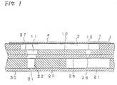
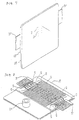
- Figs. 1 and 2 are respectively a cross-sectional view and an exploded perspective view showing a preferred embodiment of a multi-layer ink jet recording head constructed in accordance with the invention.
- reference numeral 1 designates a spacer member made of a ceramic plate of zirconia (ZrO 2 ) or the like having a thickness of 150 ⁇ m.
- the spacer member 1 has a number of elongated holes formed at predetermined intervals therein, thus forming pressure chambers 2.
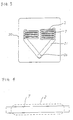
- Each of the elongated holes 2 has one end portion located over a reservoir 21 as shown in Fig. 3, and the other end portion located over a nozzle opening 31.
- a diaphragm 4 is fixedly mounted on one surface of the spacer member 1.
- the diaphragm 4 is made of a material which, when fired together with the spacer member 1, is compatible in characteristics with the latter, and it has a high elastic modulus.
- the diaphragm 4 is made of a thin zirconia plate 10 ⁇ m in thickness, similar to the spacer member.
- electrodes 5 for applying drive signals to piezoelectric transducers 7 are provided in correspondence to the pressure chambers 2, and lead-out electrodes 6 of a common electrode (described below) are provided.
- the piezoelectric transducers 7 cover the drive signal applying electrodes 5. More specifically, each of the transducers 7 is made of a thin plate of piezoelectric vibrating material such as PZT, which is substantially equal in length to the pressure chamber 2 but smaller in width than the latter, as shown in Fig. 4. That is, the transducer 7 is designed so that it flexes in such a manner as to curve in the direction of width with the longitudinal direction as an axis. As shown in Figs. 5 and 6, the aforementioned common electrode 8 is formed on the piezoelectric transducers 7 and the lead-out electrodes 6, for instance, by sputtering. That is, the lower surface (on the side of the diaphragm 4) of each piezoelectric transducer 7 is connected to the drive signal applying electrode 5, and the upper surface is connected to the common electrode 8.
- PZT piezoelectric vibrating material
- reference numeral 10 designates a lid member which, together with the diaphragm 4, forms the pressure chambers 2.
- the lid member 10 is made of a material which, when fired together with the spacer member 1, is compatible in characteristics with the latter. In this embodiment, it is made of a thin zirconia plate 150 ⁇ m in thickness.
- the lid member 10 has through-holes 11 through which the nozzles openings 31 are in communication with the pressure chambers 2, and through-holes 12 through which the reservoir 21 is in communication with the pressure chambers 2.
- Reference numeral 20 designates a spacer member forming a flow path unit 35.
- the spacer member 20 is made of a corrosion-resistant plate such as a stainless steel plate 150 ⁇ m in thickness and which is suitable for formation of ink flow paths.
- the spacer member 20 has a substantially V-shaped through-hole forming the aforementioned reservoir 21, and through-holes 22 through which the pressure chambers 2 are in communication with the nozzle openings 31.
- the through-hole forming the reservoir 21 extends radially of an ink supplying inlet member 24 and then parallel to the ends of the pressure chambers 2.
- the through-hole forming the reservoir 21 includes a V-shaped portion extending radially outward of the ink supplying inlet member 24, and two parallel portions extending from the two outer ends of the V-shaped portion along the ends of the pressure chambers 2.
- Reference numeral 26 designates an ink supplying member fixed to one surface of the above-described spacer member 20.
- the ink supplying member 26 has through-holes 27 through which the pressure chambers 2 are in communication with the nozzle openings 31, and through-holes 28 through which the reservoir 21 is in communication with the pressure chambers 2.
- the ink supplying member 26 further has the ink supplying inlet member 24 on its surface, which is connected to an ink tank (not shown).
- Reference numeral 30 designates a nozzle plate fixed to the other surface of the spacer member 20.
- the nozzle plate 30 is made of a stainless steel plate 60 ⁇ m in thickness and which is suitable for formation or nozzle openings 40 ⁇ m in diameter.
- the nozzle openings 31 in the nozzle plate 30 are formed in correspondence with the pressure chambers 2.
- the members 20, 26 and 30 are stacked one on another and fixed together as a unit using an adhesive or by welding using diffusion between metals, thereby to form the aforementioned flow path unit 35.
- the stacking of the members is performed under a high pressure; however, they can be accurately stacked one on another without intrusion or deformation although the large through-hole for forming the reservoir 21 is within in the stack because the members are made of metal, as described above.
- the pressure generating unit 15 and the flow path unit 35 are joined through their confronting surfaces, namely, the contact surfaces of the lid member 10 and the ink supplying member 26, with an adhesive, thereby to form the recording head.
- the pressure chambers 2 are in communication through the through-holes 12 of the lid member 10 and the through-holes 28 or the ink supplying member 26 with the reservoir 21, and they are further in communication through the through-holes 11 of the lid member 10, the through-holes 27 of the ink supplying member 26 and the through-holes 22 of the spacer member 20 with the nozzle openings 31.
- Figs. 7 and 8 show the front and rear structures of the multi-layer ink jet type recording head according to the invention.
- the nozzle openings are arranged in two lines at predetermined intervals.
- the pressure generating unit 15 is fixedly secured to the flow path unit 35, and cables 37 are provided for applying electrical signals to the piezoelectric transducers 7.
- the respective transducer 7 When a drive signal is applied to any one of the piezoelectric transducers 7, the respective transducer 7 is flexed in the direction of width with the longitudinal direction as an axis, thus deforming the diaphragm 7 towards the pressure chamber as shown in Fig. 9. As a result, the volume of the corresponding pressure chamber 2 is decreased; that is, pressure is applied to the ink in the pressure chamber. Hence, the ink in the pressure chamber 2 is forced to move through the corresponding through-hole 11 of the lid member 10, the through-hole 27 of the ink supplying member 26 and the through-hole 22 of the spacer member 20 in the flow path unit 35 into the nozzle opening 31, from which it is jetted in the form of an ink droplet.
- the ink flow paths extending from the pressure chambers 2 to the nozzle openings 31 are defined by the through-holes 11, 27 and 22, which are formed in the lid member 10, the ink supplying member 26 and the spacer member 20, respectively.
- the through-holes 11, 27 and 22 are reduced in diameter in the stated order, which substantially prevents air from entering into the pressure chamber through the ink flow path even when the meniscus of the ink in the nozzle is destroyed and drawn toward the pressure chamber.
- the ink in the pressure chamber 2 may flow through the through-holes 12 and 28 into the reservoir 21; however, since the through-hole 28 is small in diameter, this flow of ink will not greatly, reduce the pressure; that is, it will not adversely affect the jetting of the ink droplet.
- the volume of the pressure chamber 2 is increased so that a negative pressure is formed in the pressure chamber 2.
- the same amount of ink as previously consumed is supplied from the reservoir 21 through the through-holes 28 and 12 into the pressure chamber 2.
- the negative pressure in the pressure chamber 2 acts on the nozzle opening 31; however, the meniscus in the nozzle openings prevents the ink from returning towards the pressure chambers. Therefore, the negative pressure is effective in sucking the ink from the reservoir 21.
- the flow path unit 35 is connected to the pressure generating unit 15 through a thick layer of macromolecular adhesive about 30 ⁇ m in thickness. Therefore, even it, when the ambient temperature changes, the two units 35 and 15 are urged to shift relative to each other because of a difference in thermal expansion, the shift is absorbed by the layer of macromolecular adhesive, so that the nozzle plate is prevented from being bent; that is, the layer of macromolecular adhesive prevents the formation of prints low in quality.
- a ceramic material having a thickness suitable for formation of the pressure chambers 2 by firing is prepared.
- a thin plate of zirconia having a clay-like consistency namely, "a green sheet” is used for formation of a first sheet 40.
- a press is used to form through-holes 41 in the green sheet at the positions where the pressure chambers 2 are to be formed.
- a second sheet 42 is machined on the press. That is, through-holes 43 and 44 through which the reservoir 21 is in communication with the nozzle openings 31 are formed in a green sheet of zirconia having a thickness suitable for formation of the lid member 10.
- the first sheet 40 is set on the second sheet 42, and a third sheet 45 is placed on the first sheet 40, which is made of a green sheet of zirconia having a thickness suitable for formation of the diaphragm 4.
- the three sheets 40, 42 and 45 are joined to one another under uniform pressure, and then dried. In this drying step, the three sheets 40, 42 and 45 are temporarily bonded together and semi-solidified.
- the assembly of these sheets is fired at a predetermined temperature, for instance 1000°C, while the assembly is pressurized to the extent that the assembly is prevented from bending. As a result, the sheets are transformed into ceramic plates, the interfaces of which are combined together by firing. That is, they are formed into an integral unit.
- the through-holes 41 forming the pressure chambers are formed in the first sheet 40.
- the through-holes 41 are extremely small in width.
- the second and third sheets 42 and 45 which form the lid member and the diaphragm, respectively
- the pressure is suitably concentrated at the through-holes 41, which contributes to the combining of the second and third sheets 42 and 45 with the first sheet 40 by firing.
- the volume of each pressure chamber can be set as required.
- the first, second and third sheets 40, 42 and 45 thus fired function as a space member 50, a lid member 51 and a diaphragm 52, respectively.
- electrically conductive paste layers are formed on the surface of the diaphragm 52 at the positions of the pressure chambers 53 and of the common electrode lead-out terminals by a thick film printing method.
- Relatively thick layers of piezoelectric materials of a clay-like consistency are formed with a mask by printing so as to provide through-holes in correspondence to the pressure chambers 53.
- the whole assembly is heated at a temperature suitable for firing the piezoelectric transducers and the electrodes, for instance, in a range of from 1000°C to 1200°C.
- the piezoelectric transducers 54 are formed for the respective pressure chambers 53 (see Fig. 10 (II)).
- the pressure generating unit is formed, which appears as if it were made of a single component although it includes the diaphragm, the spacer member and the lid member.
- an ink supplying member 60, a reservoir forming member 66, and a nozzle plate member 69 are prepared using metal plates having respective predetermined thicknesses. That is, the ink supplying member 60 is formed by forming through-holes 61 and 62, which correspond to the through-holes 27 and the flow path regulating holes 28, in the metal plate on the press.
- the reservoir forming member 66 is formed by cutting through-holes 64 and 65, which correspond to the reservoir 21 and the through-holes 22, in the metal plate on the press.
- the nozzle plate member 69 is also formed by forming through-holes 68, which correspond to the nozzle openings 31, in the metal plate on the press. As shown in Fig.
- a bonding film 75 having through-holes 70 and a through-hole 71 is inserted between the members 60 and 66, while a bonding film 76 having through-holes 72 and a through-hole 73 is inserted between the members 66 and 69.
- the through-holes 70, 71, 72 and 73 are formed in the bonding films 75 and 76 in such a manner that the remaining portions of the films 75 and 76, namely, the bonding regions thereof, do not cover the through-holes 61, 62, 64, 65 and 68 of the members 60, 66 and 69.
- the members 60, 64 and 69 and the films 75 and 76 which have been stacked in the above-described manner, are thermally bonded under pressure to form the flow path unit.
- an adhesive layer 80 is formed on the surface of one of the units, for instance, the surface of the ink supplying member 60, by coating it with adhesive or by using a thermal welding film (see Fig. 10(IV)), and the lid member 51 of the pressure generating unit is placed on the adhesive layer 80 thus formed in such a manner that the through-holes 56 and 57 are coaxial with the through-holes 62 and 61 (Fig. 10(V)).
- an adhesive layer 81 is formed between the flow path unit and the pressure generating unit, which serves as a cushion member to absorb the difference in thermal expansion between the two members.
- the adhesive layer 80 spreads outward when squeezed between the two units. As shown in Fig. 12, there are provided regions 82 around the through-holes where no adhesive is provided, thereby to prevent the adhesive from spreading into the through-holes of the lid member 51 and the ink supplying member 60.
- the pressure generating unit is made of ceramic, which has a lower density than metal, and therefore vibration propagating between adjacent piezoelectric transducers is greatly attenuated; that is, crosstalk is prevented. Furthermore, the elements forming the vibrating portion of the recording head of the invention are joined as an integral unit without the intrusion of any foreign member. This feature positively eliminates the difficulty of ink leaking because of inadequate adhesion.
- the base of the pressure generating unit and the ceramics forming the vibration generating unit are fired at temperatures suitable therefor.
- the operation of the recording head is high in reliability.
- the multi-layer ink jet type recording head of the invention comprises a pressure generating unit and a flow path unit.
- the pressure generating unit includes the first plate member of ceramics forming the vibrating member with the piezoelectric transducers on the surface thereof, the first spacer member of ceramics with the through-holes forming the pressure chambers, and the lid member having the through-holes through which the pressure chambers are in communication with the reservoir, which members are joined in such a manner that the first plate member is placed on one surface of the first spacer member, and the lid member is sealingly set on the other surface of the spacer member.
- the flow path unit includes the ink supplying member made of a metal plate which is connected through the flow path to the ink tank and which has the through-holes through which the pressure chambers are in communication with the nozzle openings and the reservoir is in communication with the pressure chambers, the second spacer member having the reservoir and the through-holes through which the pressure chambers are in communication with the nozzle openings, and the nozzle plate member with the nozzle openings, these members being joined together in such a manner that the ink supplying member is placed on one surface of the second spacer member, and the nozzle plate member is fixedly placed on the other surface.
- the outer surface of the lid member is joined to the outer surface of the ink supplying member with a macromolecular adhesive agent.
- the pressure generating unit for producing pressure to jet ink droplets is formed by firing the members made of ceramic. Therefore, the pressure generating unit is advantageous in that it has a very good liquid tightness, and the signal applying electrodes can be installed directly thereon.
- the flow path unit having a relatively large recess to form the reservoir is made of metal, and thus is high in rigidity.
- the ceramic pressure generating unit and the metal flow path unit are joined together with a macromolecular adhesive agent relatively high in elasticity. Hence, bending of these units due to the difference in thermal expansion is positively prevented. As a result, the ink jet type recording head of the invention can be made relatively small in thickness, and it is high in reliability.
Description
- The present invention relates to a multi-layer ink jet type recording head.
- An ink jet type recording head is known in which piezoelectric transducers are coupled to diaphragms which form walls of respective ink pressure chambers, wherein displacement of the piezoelectric transducers varies the volume of the pressure chambers to thereby eject ink droplets. Such a recording head is advantageous in that, since the displacement of the diaphragms by the piezoelectric transducers takes place over a relatively large area of the pressure chambers, ink droplets can be formed stably.
- However, the recording head is still disadvantageous in that, since ink droplets are jetted in a direction perpendicular to the direction of displacement of the diaphragm, the recording head is unavoidably large in the direction perpendicular to the surface of the recording sheet, and accordingly the carriage supporting and transporting the recording head and its related components are also unavoidably large in this direction.
- In order to overcome the above-described difficulty, an ink jet type recording head has been proposed, for example, in Japanese Unexamined Patent Publication No. Sho. 62-111758, in which pressure generating members including diaphragms and ink flow path forming members are formed in a layered construction, and nozzle openings are provided in a row extending parallel to the direction of displacement of the diaphragm, thereby to reduce the thickness of the recording head. That is, the recording head has a layered structure.
- The layered structure is advantageous in that the recording head can be miniaturized, and it can be manufactured using a simple method for joining plate members formed by pressing or etching.
- In the manufacturing method for producing the recording head, an adhesive agent is used for joining the plate members However, during manufacture, the adhesive agent can sometimes flow into small holes which form ink flow paths in the plate members, thus changing the ink flow resistance thereof, lowering the reliability in operation of the recording head. Furthermore, because the piezoelectric transducers must be fixed to the diaphragm with an adhesive agent or by etching or laser welding, the manufacture of the recording head requires much time and labor.
- In order to eliminate the above-described difficulties, an ink jet type recording head has been proposed, for example, in Japanese Unexamined Patent Publication No. Sho. 63-149159, which is formed by layering ceramic plates in a semi-solid state, shaped as required to form flow path members, and piezoelectric transducers, one on another and subjecting the structure to firing. That is, the recording head is manufactured without a separate step of mounting the piezoelectric transducers. However, the method is still disadvantageous in that it cannot achieve a reduction in the thickness of the recording head since the nozzle openings extend in a direction perpendicular to the direction of displacement of the diaphragm, similar to the above-described recording head.
- It is therefore the object of the present invention to provide an ink jet recording head which avoids the above mentioned drawbacks. This object is solved by the actuator unit for an ink jet recording head according to
independent claim 1. - Further advantageous features, aspects and details of the invention are evident from the dependent claims, the description and the drawings.
- An ink jet recording head in which piezoelectric transducers provided in parts of pressure chambers communicated with nozzle openings compress the pressure chambers to form ink droplets. The ink jet type recording head is especially formed by arranging a nozzle plate, pressure chamber forming members and a vibrating plate one on another.
- In this ink jet type recording head the manufacturing assembly accuracy is improved, the number of steps required for joining the relevant members is minimized, and the nozzle openings are provided in parallel with the direction of displacement of the diaphragms to reduce the thickness of the recording head.
- A multi-layer ink jet type recording head is manufactured as follows: A first plate member of ceramic forming a vibrating member with piezoelectric transducers on the surface thereof, a first spacer member made of ceramics with a plurality of through-holes therein forming pressure chambers, and a lid member having through-holes through which the pressure chambers are in communication with a reservoir are joined together to form a pressure generating unit in such a manner that the first plate member is placed on one surface of the first spacer member, and the lid member is sealingly set on the other surface of the spacer member. An ink supplying member made of a metal plate and which is connected through a flow path to an ink tank and has through-holes through which the pressure chambers are communicating with nozzle openings and the reservoir is in communication with the pressure chambers, a second spacer member having through-holes through which the pressure chambers are in communication with the reservoir and the nozzle openings, and a nozzle plate member with the nozzle openings formed therein are joined together to form a flow path unit in such a manner that the ink supplying member is placed on one surface of the second spacer member, and the nozzle plate member is fixedly placed on the other surface of the second spacer member. The outer surface of the lid member in the pressure generating unit is joined to the outer surface of the ink supplying member in the flow path unit with a macromolecular adhesive agent.
- In the pressure generating unit, which is made of ceramic, small through-holes are formed in the spacer member, which simplifies the manufacturing step of joining the vibrating member, the spacer member and the lid member, and positively prevents leakage of ink past the unit, to which high pressure is exerted. The flow path unit, which is made of metal, has a relatively large through-hole to form the reservoir in the space member, and therefore it is high in dimensional accuracy. The pressure generating unit and the flow path unit are joined together with a macromolecular adhesive layer, so that the difference in thermal expansion between the two units, which are made of different materials as described above, can be absorbed.
- Further details and advantages of the invention will be apparent from the following detailed description, in which:
- Fig. 1 is a sectional view showing a multi-layer type ink jet type recording head constructed in accordance with a preferred embodiment of the invention;
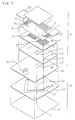
- Fig. 2 is an exploded perspective view of the recording head shown in Fig. 1;
- Fig. 3 is an explanatory diagram showing the positional relationships between pressure chambers in the recording head;
- Fig. 4 is an explanatory diagram showing the position of a piezoelectric transducer in the recording head;
- Fig. 5 is a perspective view showing the positional relationships between piezoelectric transducers and electrodes in the recording head;
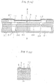
- Fig. 6 is a sectional view taken along a line A-A in Fig. 5 showing the structure of the piezoelectric transducer mounted on a diaphragm in the recording head;
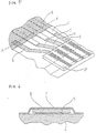
- Fig. 7 is a perspective view outlining the recording head;
- Fig. 8 is a perspective view showing the rear structure of the recording head;
- Figs. 9(a) and 9(b) are, respectively, a longitudinal sectional view and a cross-sectional view taken along a line B-B in in Fig. 9(a) showing the recording head jetting an ink droplet;
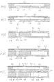
- Fig. 10(I) - 10(V) are sectional views for a description of a method for manufacturing a multi-layer type ink jet type recording head according to the invention;
- Fig. 11 is an exploded view for a description of a step of joining plates together to form a flow path unit; and
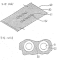
- Figs. 12(a) and 12(b) are diagrams showing an adhesive layer through which the flow path unit is joined to a pressure generating unit.
-
- Preferred embodiments of the invention will now be described with reference to the accompanying drawings.
- Figs. 1 and 2 are respectively a cross-sectional view and an exploded perspective view showing a preferred embodiment of a multi-layer ink jet recording head constructed in accordance with the invention. In these figures,
reference numeral 1 designates a spacer member made of a ceramic plate of zirconia (ZrO2) or the like having a thickness of 150 µm. Thespacer member 1 has a number of elongated holes formed at predetermined intervals therein, thus formingpressure chambers 2. Each of theelongated holes 2 has one end portion located over areservoir 21 as shown in Fig. 3, and the other end portion located over a nozzle opening 31. Adiaphragm 4 is fixedly mounted on one surface of thespacer member 1. Thediaphragm 4 is made of a material which, when fired together with thespacer member 1, is compatible in characteristics with the latter, and it has a high elastic modulus. In this embodiment, thediaphragm 4 is made of athin zirconia plate 10 µm in thickness, similar to the spacer member. As shown in Fig. 5, on the surface of thediaphragm 4,electrodes 5 for applying drive signals topiezoelectric transducers 7 are provided in correspondence to thepressure chambers 2, and lead-outelectrodes 6 of a common electrode (described below) are provided. - The
piezoelectric transducers 7 cover the drivesignal applying electrodes 5. More specifically, each of thetransducers 7 is made of a thin plate of piezoelectric vibrating material such as PZT, which is substantially equal in length to thepressure chamber 2 but smaller in width than the latter, as shown in Fig. 4. That is, thetransducer 7 is designed so that it flexes in such a manner as to curve in the direction of width with the longitudinal direction as an axis. As shown in Figs. 5 and 6, the aforementionedcommon electrode 8 is formed on thepiezoelectric transducers 7 and the lead-out electrodes 6, for instance, by sputtering. That is, the lower surface (on the side of the diaphragm 4) of eachpiezoelectric transducer 7 is connected to the drivesignal applying electrode 5, and the upper surface is connected to thecommon electrode 8. - Further in Figs. 1 and 2,
reference numeral 10 designates a lid member which, together with thediaphragm 4, forms thepressure chambers 2. Thelid member 10 is made of a material which, when fired together with thespacer member 1, is compatible in characteristics with the latter. In this embodiment, it is made of a thin zirconia plate 150 µm in thickness. Thelid member 10 has through-holes 11 through which the nozzles openings 31 are in communication with thepressure chambers 2, and through-holes 12 through which thereservoir 21 is in communication with thepressure chambers 2. - The above-described
members pressure generating unit 15. -
Reference numeral 20 designates a spacer member forming aflow path unit 35. Thespacer member 20 is made of a corrosion-resistant plate such as a stainless steel plate 150 µm in thickness and which is suitable for formation of ink flow paths. Thespacer member 20 has a substantially V-shaped through-hole forming theaforementioned reservoir 21, and through-holes 22 through which thepressure chambers 2 are in communication with thenozzle openings 31. The through-hole forming thereservoir 21 extends radially of an ink supplyinginlet member 24 and then parallel to the ends of thepressure chambers 2. More specifically, in the embodiment having the nozzle openings in two lines, the through-hole forming thereservoir 21 includes a V-shaped portion extending radially outward of the ink supplyinginlet member 24, and two parallel portions extending from the two outer ends of the V-shaped portion along the ends of thepressure chambers 2. -
Reference numeral 26 designates an ink supplying member fixed to one surface of the above-describedspacer member 20. Theink supplying member 26 has through-holes 27 through which thepressure chambers 2 are in communication with thenozzle openings 31, and through-holes 28 through which thereservoir 21 is in communication with thepressure chambers 2. Theink supplying member 26 further has the ink supplyinginlet member 24 on its surface, which is connected to an ink tank (not shown). -
Reference numeral 30 designates a nozzle plate fixed to the other surface of thespacer member 20. Thenozzle plate 30 is made of astainless steel plate 60 µm in thickness and which is suitable for formation ornozzle openings 40 µm in diameter. Thenozzle openings 31 in thenozzle plate 30 are formed in correspondence with thepressure chambers 2. - The
members flow path unit 35. In this operation, the stacking of the members is performed under a high pressure; however, they can be accurately stacked one on another without intrusion or deformation although the large through-hole for forming thereservoir 21 is within in the stack because the members are made of metal, as described above. - The
pressure generating unit 15 and theflow path unit 35 are joined through their confronting surfaces, namely, the contact surfaces of thelid member 10 and theink supplying member 26, with an adhesive, thereby to form the recording head. - Thus, the
pressure chambers 2 are in communication through the through-holes 12 of thelid member 10 and the through-holes 28 or theink supplying member 26 with thereservoir 21, and they are further in communication through the through-holes 11 of thelid member 10, the through-holes 27 of theink supplying member 26 and the through-holes 22 of thespacer member 20 with thenozzle openings 31. - Figs. 7 and 8 show the front and rear structures of the multi-layer ink jet type recording head according to the invention. In the front structure, the nozzle openings are arranged in two lines at predetermined intervals. In the rear structure, the
pressure generating unit 15 is fixedly secured to theflow path unit 35, andcables 37 are provided for applying electrical signals to thepiezoelectric transducers 7. - When a drive signal is applied to any one of the
piezoelectric transducers 7, therespective transducer 7 is flexed in the direction of width with the longitudinal direction as an axis, thus deforming thediaphragm 7 towards the pressure chamber as shown in Fig. 9. As a result, the volume of thecorresponding pressure chamber 2 is decreased; that is, pressure is applied to the ink in the pressure chamber. Hence, the ink in thepressure chamber 2 is forced to move through the corresponding through-hole 11 of thelid member 10, the through-hole 27 of theink supplying member 26 and the through-hole 22 of thespacer member 20 in theflow path unit 35 into thenozzle opening 31, from which it is jetted in the form of an ink droplet. - The ink flow paths extending from the
pressure chambers 2 to thenozzle openings 31 are defined by the through-holes lid member 10, theink supplying member 26 and thespacer member 20, respectively. The through-holes pressure chamber 2 may flow through the through-holes reservoir 21; however, since the through-hole 28 is small in diameter, this flow of ink will not greatly, reduce the pressure; that is, it will not adversely affect the jetting of the ink droplet. - When the application of the drive signal is suspended, that is, when the
piezoelectric transducer 7 is restored to its unexcited state, the volume of thepressure chamber 2 is increased so that a negative pressure is formed in thepressure chamber 2. As a result, the same amount of ink as previously consumed is supplied from thereservoir 21 through the through-holes pressure chamber 2. The negative pressure in thepressure chamber 2 acts on thenozzle opening 31; however, the meniscus in the nozzle openings prevents the ink from returning towards the pressure chambers. Therefore, the negative pressure is effective in sucking the ink from thereservoir 21. - The
flow path unit 35 is connected to thepressure generating unit 15 through a thick layer of macromolecular adhesive about 30 µm in thickness. Therefore, even it, when the ambient temperature changes, the twounits - A method for manufacturing the above-described recording head now will be described with reference to Fig. 10.
- A ceramic material having a thickness suitable for formation of the
pressure chambers 2 by firing is prepared. In the present embodiment, a thin plate of zirconia having a clay-like consistency, namely, "a green sheet" is used for formation of afirst sheet 40. A press is used to form through-holes 41 in the green sheet at the positions where thepressure chambers 2 are to be formed. Similarly as in the case of the first sheet, asecond sheet 42 is machined on the press. That is, through-holes 43 and 44 through which thereservoir 21 is in communication with thenozzle openings 31 are formed in a green sheet of zirconia having a thickness suitable for formation of thelid member 10. - The
first sheet 40 is set on thesecond sheet 42, and athird sheet 45 is placed on thefirst sheet 40, which is made of a green sheet of zirconia having a thickness suitable for formation of thediaphragm 4. The threesheets sheets - As described above, the through-
holes 41 forming the pressure chambers are formed in thefirst sheet 40. The through-holes 41 are extremely small in width. Hence, when the three sheets are temporarily bonded together, the second andthird sheets 42 and 45 (which form the lid member and the diaphragm, respectively) are not deformed, and the pressure is suitably concentrated at the through-holes 41, which contributes to the combining of the second andthird sheets first sheet 40 by firing. Thus, the volume of each pressure chamber can be set as required. - The first, second and
third sheets space member 50, alid member 51 and adiaphragm 52, respectively. In this state, electrically conductive paste layers are formed on the surface of thediaphragm 52 at the positions of thepressure chambers 53 and of the common electrode lead-out terminals by a thick film printing method. Relatively thick layers of piezoelectric materials of a clay-like consistency are formed with a mask by printing so as to provide through-holes in correspondence to thepressure chambers 53. When the thick layers have been dried to the extent that they are suitable for firing the transducer-forming materials, the whole assembly is heated at a temperature suitable for firing the piezoelectric transducers and the electrodes, for instance, in a range of from 1000°C to 1200°C. Thus, thepiezoelectric transducers 54 are formed for the respective pressure chambers 53 (see Fig. 10 (II)). - Thereafter, a layer of electrically conductive material is formed over the common electrode lead-out terminals and the
piezoelectric transducers 54 by a thin film forming method such as a sputtering method. Thus, the pressure generating unit is formed, which appears as if it were made of a single component although it includes the diaphragm, the spacer member and the lid member. - On the other hand, an
ink supplying member 60, areservoir forming member 66, and anozzle plate member 69 are prepared using metal plates having respective predetermined thicknesses. That is, theink supplying member 60 is formed by forming through-holes holes 27 and the flowpath regulating holes 28, in the metal plate on the press. Thereservoir forming member 66 is formed by cutting through-holes reservoir 21 and the through-holes 22, in the metal plate on the press. Thenozzle plate member 69 is also formed by forming through-holes 68, which correspond to thenozzle openings 31, in the metal plate on the press. As shown in Fig. 11, abonding film 75 having through-holes 70 and a through-hole 71 is inserted between themembers bonding film 76 having through-holes 72 and a through-hole 73 is inserted between themembers holes bonding films films holes members members films - The pressure generating unit and the flow path unit are joined as follows: As shown in Fig. 12(a), an
adhesive layer 80 is formed on the surface of one of the units, for instance, the surface of theink supplying member 60, by coating it with adhesive or by using a thermal welding film (see Fig. 10(IV)), and thelid member 51 of the pressure generating unit is placed on theadhesive layer 80 thus formed in such a manner that the through-holes holes 62 and 61 (Fig. 10(V)). As a result, anadhesive layer 81 is formed between the flow path unit and the pressure generating unit, which serves as a cushion member to absorb the difference in thermal expansion between the two members. Theadhesive layer 80 spreads outward when squeezed between the two units. As shown in Fig. 12, there are providedregions 82 around the through-holes where no adhesive is provided, thereby to prevent the adhesive from spreading into the through-holes of thelid member 51 and theink supplying member 60. - In the recording head of the invention, the pressure generating unit is made of ceramic, which has a lower density than metal, and therefore vibration propagating between adjacent piezoelectric transducers is greatly attenuated; that is, crosstalk is prevented. Furthermore, the elements forming the vibrating portion of the recording head of the invention are joined as an integral unit without the intrusion of any foreign member. This feature positively eliminates the difficulty of ink leaking because of inadequate adhesion.
- Furthermore, in the recording head of the invention, the base of the pressure generating unit and the ceramics forming the vibration generating unit are fired at temperatures suitable therefor. Thus, the operation of the recording head is high in reliability.
- As described above, the multi-layer ink jet type recording head of the invention comprises a pressure generating unit and a flow path unit. The pressure generating unit includes the first plate member of ceramics forming the vibrating member with the piezoelectric transducers on the surface thereof, the first spacer member of ceramics with the through-holes forming the pressure chambers, and the lid member having the through-holes through which the pressure chambers are in communication with the reservoir, which members are joined in such a manner that the first plate member is placed on one surface of the first spacer member, and the lid member is sealingly set on the other surface of the spacer member. The flow path unit includes the ink supplying member made of a metal plate which is connected through the flow path to the ink tank and which has the through-holes through which the pressure chambers are in communication with the nozzle openings and the reservoir is in communication with the pressure chambers, the second spacer member having the reservoir and the through-holes through which the pressure chambers are in communication with the nozzle openings, and the nozzle plate member with the nozzle openings, these members being joined together in such a manner that the ink supplying member is placed on one surface of the second spacer member, and the nozzle plate member is fixedly placed on the other surface. The outer surface of the lid member is joined to the outer surface of the ink supplying member with a macromolecular adhesive agent. That is, the pressure generating unit for producing pressure to jet ink droplets is formed by firing the members made of ceramic. Therefore, the pressure generating unit is advantageous in that it has a very good liquid tightness, and the signal applying electrodes can be installed directly thereon. On the other hand, the flow path unit having a relatively large recess to form the reservoir is made of metal, and thus is high in rigidity. In addition, the ceramic pressure generating unit and the metal flow path unit are joined together with a macromolecular adhesive agent relatively high in elasticity. Hence, bending of these units due to the difference in thermal expansion is positively prevented. As a result, the ink jet type recording head of the invention can be made relatively small in thickness, and it is high in reliability.
Claims (2)
- A layer-built ink jet type recording head comprising:A. a pressure generating unit (15) comprising:(1) a first plate member (4) forming a vibrating member having piezoelectric transducers (7) on a surface thereof,(2) a first spacer member (1) having formed therein a plurality of through-holes forming pressure chambers (2), and(3) a lid member (10) having through-holes (11) formed therein through which said pressure chambers (2) are in communication with a reservoir (21),
said first plate member, said first spacer member (1) and said lid member (10) being integrally connected to one another in such a manner that said first plate member is placed on one surface of said first spacer member (1) and said lid member (10) is sealingly set on the other surface of said space member (1);B. a flow path unit (35) comprising:(1) an ink supplying member (26) made of a metal plate, said ink supplying member (26) being connected through a flow path to an ink tank, and said ink supplying member (26) having through-holes (27,28) formed therein through which said pressure chambers (2) are in communication with nozzle openings (31) and said reservoir (21) is in communication with said pressure chambers (2),(2) a second spacer member (20) having said reservoir (21) and through-holes (22) through which said pressure chambers (2) are in communication with said nozzle openings (31), and (3) a nozzle plate member (30) having said nozzle openings (31) formed therein,said ink supplying member (26), said spacer member (20) and said nozzle plate member (30) being integrally connected to one another in such a manner that said ink supplying member (26) is placed on one surface of said second spacer member (20) and said nozzle plate member (30) is fixedly placed on the other surface of said second spacer member (20); andC. an adhesive agent integrally joining an outer surface of said lid member (10) to the outer surface of said ink supplying member (26), wherein:
at said joining surfaces, the area of said flow path unit (35) is larger than the area of said pressure generating unit (15). - The multi-layer ink jet type recording head according to claim 1, wherein said flow path unit (35) is formed by thermally bonding under pressure said ink supplying member (26), said spacer member (20) and said nozzle plate member (30) and bonding films in such a manner that said bonding films do not cover said through-holes (27) of said ink supplying member (26) and said through-holes (22) of said spacer member (20).
Priority Applications (1)
| Application Number | Priority Date | Filing Date | Title |
|---|---|---|---|
| EP99125430A EP0988972B1 (en) | 1992-08-26 | 1993-08-26 | Layer-built ink jet recording head |
Applications Claiming Priority (14)
| Application Number | Priority Date | Filing Date | Title |
|---|---|---|---|
| JP22750392 | 1992-08-26 | ||
| JP227503/92 | 1992-08-26 | ||
| JP22750392 | 1992-08-26 | ||
| JP273149/92 | 1992-10-12 | ||
| JP27314992 | 1992-10-12 | ||
| JP27314992 | 1992-10-12 | ||
| JP33459292 | 1992-12-15 | ||
| JP33459292 | 1992-12-15 | ||
| JP334592/92 | 1992-12-15 | ||
| JP8007093 | 1993-03-15 | ||
| JP80070/93 | 1993-03-15 | ||
| JP08007093A JP3317308B2 (en) | 1992-08-26 | 1993-03-15 | Laminated ink jet recording head and method of manufacturing the same |
| EP93113684A EP0584823B1 (en) | 1992-08-26 | 1993-08-26 | Ink jet recording head and manufacturing method therefor |
| EP96104186A EP0723867B1 (en) | 1992-08-26 | 1993-08-26 | Pressure generating unit for an ink jet recording head |
Related Parent Applications (3)
| Application Number | Title | Priority Date | Filing Date |
|---|---|---|---|
| EP96104186A Division EP0723867B1 (en) | 1992-08-26 | 1993-08-26 | Pressure generating unit for an ink jet recording head |
| EP93113684.0 Division | 1993-08-26 | ||
| EP96104186.0 Division | 1996-03-15 |
Related Child Applications (1)
| Application Number | Title | Priority Date | Filing Date |
|---|---|---|---|
| EP99125430A Division EP0988972B1 (en) | 1992-08-26 | 1993-08-26 | Layer-built ink jet recording head |
Publications (3)
| Publication Number | Publication Date |
|---|---|
| EP0839655A2 EP0839655A2 (en) | 1998-05-06 |
| EP0839655A3 EP0839655A3 (en) | 1998-05-20 |
| EP0839655B1 true EP0839655B1 (en) | 2001-01-17 |
Family
ID=27466383
Family Applications (4)
| Application Number | Title | Priority Date | Filing Date |
|---|---|---|---|
| EP96104186A Expired - Lifetime EP0723867B1 (en) | 1992-08-26 | 1993-08-26 | Pressure generating unit for an ink jet recording head |
| EP98102295A Expired - Lifetime EP0839655B1 (en) | 1992-08-26 | 1993-08-26 | Multi-layer ink jet recording head |
| EP93113684A Expired - Lifetime EP0584823B1 (en) | 1992-08-26 | 1993-08-26 | Ink jet recording head and manufacturing method therefor |
| EP99125430A Expired - Lifetime EP0988972B1 (en) | 1992-08-26 | 1993-08-26 | Layer-built ink jet recording head |
Family Applications Before (1)
| Application Number | Title | Priority Date | Filing Date |
|---|---|---|---|
| EP96104186A Expired - Lifetime EP0723867B1 (en) | 1992-08-26 | 1993-08-26 | Pressure generating unit for an ink jet recording head |
Family Applications After (2)
| Application Number | Title | Priority Date | Filing Date |
|---|---|---|---|
| EP93113684A Expired - Lifetime EP0584823B1 (en) | 1992-08-26 | 1993-08-26 | Ink jet recording head and manufacturing method therefor |
| EP99125430A Expired - Lifetime EP0988972B1 (en) | 1992-08-26 | 1993-08-26 | Layer-built ink jet recording head |
Country Status (6)
| Country | Link |
|---|---|
| US (2) | US6270203B1 (en) |
| EP (4) | EP0723867B1 (en) |
| JP (1) | JP3317308B2 (en) |
| DE (4) | DE69333824T2 (en) |
| HK (2) | HK1002121A1 (en) |
| SG (3) | SG115367A1 (en) |
Cited By (4)
| Publication number | Priority date | Publication date | Assignee | Title |
|---|---|---|---|---|
| US7988247B2 (en) | 2007-01-11 | 2011-08-02 | Fujifilm Dimatix, Inc. | Ejection of drops having variable drop size from an ink jet printer |
| US8459768B2 (en) | 2004-03-15 | 2013-06-11 | Fujifilm Dimatix, Inc. | High frequency droplet ejection device and method |
| US8491076B2 (en) | 2004-03-15 | 2013-07-23 | Fujifilm Dimatix, Inc. | Fluid droplet ejection devices and methods |
| US8708441B2 (en) | 2004-12-30 | 2014-04-29 | Fujifilm Dimatix, Inc. | Ink jet printing |
Families Citing this family (81)
| Publication number | Priority date | Publication date | Assignee | Title |
|---|---|---|---|---|
| JP3317308B2 (en) * | 1992-08-26 | 2002-08-26 | セイコーエプソン株式会社 | Laminated ink jet recording head and method of manufacturing the same |
| US6601949B1 (en) | 1992-08-26 | 2003-08-05 | Seiko Epson Corporation | Actuator unit for ink jet recording head |
| JP3136455B2 (en) * | 1993-07-26 | 2001-02-19 | 日本碍子株式会社 | Method of bonding plates constituting an inkjet printhead |
| IL106803A (en) * | 1993-08-25 | 1998-02-08 | Scitex Corp Ltd | Ink jet print head |
| IT1268870B1 (en) * | 1993-08-23 | 1997-03-13 | Seiko Epson Corp | INKJET REGISTRATION HEAD AND PROCEDURE FOR ITS MANUFACTURING. |
| EP1170127B1 (en) * | 1993-12-24 | 2005-10-19 | Seiko Epson Corporation | Ink jet recording head |
| EP0661156B1 (en) | 1993-12-28 | 2000-03-22 | Seiko Epson Corporation | Ink jet recording head |
| JPH07276630A (en) * | 1994-04-12 | 1995-10-24 | Rohm Co Ltd | Ink jet print head and ink jet printer |
| DE19515406C2 (en) * | 1994-04-26 | 1999-04-01 | Seiko Epson Corp | Ink jet printhead and manufacturing method for the ink jet printhead |
| JP3250596B2 (en) * | 1994-07-01 | 2002-01-28 | セイコーエプソン株式会社 | Ink jet recording device |
| US5748214A (en) * | 1994-08-04 | 1998-05-05 | Seiko Epson Corporation | Ink jet recording head |
| JP3196811B2 (en) * | 1994-10-17 | 2001-08-06 | セイコーエプソン株式会社 | Laminated ink jet recording head and method of manufacturing the same |
| JPH08174860A (en) | 1994-10-26 | 1996-07-09 | Seiko Epson Corp | Ink cartridge for ink jet printer |
| JP3570447B2 (en) * | 1994-12-21 | 2004-09-29 | セイコーエプソン株式会社 | Laminated inkjet recording head, method of manufacturing the same, and recording apparatus |
| US5907338A (en) * | 1995-01-13 | 1999-05-25 | Burr; Ronald F. | High-performance ink jet print head |
| JP3366146B2 (en) * | 1995-03-06 | 2003-01-14 | セイコーエプソン株式会社 | Ink jet head |
| DE69617058T2 (en) * | 1995-06-12 | 2002-06-20 | Citizen Watch Co Ltd | Clamping device for manufacturing an inkjet head |
| JP3987139B2 (en) * | 1995-06-27 | 2007-10-03 | セイコーエプソン株式会社 | Inkjet recording head |
| US5907340A (en) * | 1995-07-24 | 1999-05-25 | Seiko Epson Corporation | Laminated ink jet recording head with plural actuator units connected at outermost ends |
| US5963234A (en) * | 1995-08-23 | 1999-10-05 | Seiko Epson Corporation | Laminated ink jet recording head having flow path unit with recess that confronts but does not communicate with common ink chamber |
| JPH09104109A (en) * | 1995-10-12 | 1997-04-22 | Sharp Corp | Ink jet head and production thereof |
| JP3173561B2 (en) * | 1995-10-31 | 2001-06-04 | セイコーエプソン株式会社 | Laminated ink jet recording head and driving method thereof |
| EP0985536B1 (en) * | 1995-11-10 | 2002-09-25 | Seiko Epson Corporation | Ink jet type recording head |
| JP3659522B2 (en) * | 1995-11-30 | 2005-06-15 | 京セラミタ株式会社 | Inkjet head |
| JP3522060B2 (en) * | 1996-10-21 | 2004-04-26 | セイコーエプソン株式会社 | Ink jet recording head and method of manufacturing ink supply port forming substrate suitable for the same |
| DE69739387D1 (en) * | 1996-10-29 | 2009-06-10 | Panasonic Corp | Ink jet recording apparatus and method for its manufacture |
| US6808250B2 (en) * | 1997-01-10 | 2004-10-26 | Konica Corporation | Production method of ink-jet head |
| JPH1148475A (en) * | 1997-07-31 | 1999-02-23 | Seiko Epson Corp | Ink jet recording head |
| EP0968825B1 (en) * | 1998-06-30 | 2005-09-14 | Canon Kabushiki Kaisha | Line head for ink-jet printer |
| JP3056195B1 (en) * | 1999-02-02 | 2000-06-26 | 新潟日本電気株式会社 | INK JET PRINT HEAD AND ITS MANUFACTURING METHOD |
| US6755511B1 (en) | 1999-10-05 | 2004-06-29 | Spectra, Inc. | Piezoelectric ink jet module with seal |
| DE60003767T2 (en) * | 1999-10-29 | 2004-06-03 | Hewlett-Packard Co. (N.D.Ges.D.Staates Delaware), Palo Alto | Inkjet printhead with improved reliability |
| JP4554135B2 (en) | 1999-12-10 | 2010-09-29 | 富士フイルム株式会社 | Inkjet head and printing apparatus |
| US6652078B2 (en) | 2000-05-23 | 2003-11-25 | Silverbrook Research Pty Ltd | Ink supply arrangement for a printer |
| US6988840B2 (en) | 2000-05-23 | 2006-01-24 | Silverbrook Research Pty Ltd | Printhead chassis assembly |
| US6786658B2 (en) | 2000-05-23 | 2004-09-07 | Silverbrook Research Pty. Ltd. | Printer for accommodating varying page thicknesses |
| US6488422B1 (en) | 2000-05-23 | 2002-12-03 | Silverbrook Research Pty Ltd | Paper thickness sensor in a printer |
| US7213989B2 (en) | 2000-05-23 | 2007-05-08 | Silverbrook Research Pty Ltd | Ink distribution structure for a printhead |
| US6409323B1 (en) | 2000-05-23 | 2002-06-25 | Silverbrook Research Pty Ltd | Laminated ink distribution assembly for a printer |
| US6526658B1 (en) | 2000-05-23 | 2003-03-04 | Silverbrook Research Pty Ltd | Method of manufacture of an ink jet printhead having a moving nozzle with an externally arranged actuator |
| AU2004202971B1 (en) * | 2000-05-24 | 2004-07-22 | Silverbrook Research Pty Ltd | Printhead with laminated ink distribution assembly |
| SG157219A1 (en) * | 2000-05-24 | 2009-12-29 | Silverbrook Res Pty Ltd | Laminated ink distribution structure for a printhead |
| AU2000247329B2 (en) * | 2000-05-24 | 2004-04-08 | Memjet Technology Limited | Laminated ink distribution assembly for a printer |
| SG149677A1 (en) | 2000-05-24 | 2009-02-27 | Silverbrook Res Pty Ltd | A printhead assembly with an ink distribution arrangement |
| SG152038A1 (en) * | 2000-05-24 | 2009-05-29 | Silverbrook Res Pty Ltd | Laminated ink distribution assembly for a printer |
| JP4748833B2 (en) * | 2000-06-22 | 2011-08-17 | パナソニック株式会社 | Ink jet head and ink jet recording apparatus |
| US6861034B1 (en) | 2000-11-22 | 2005-03-01 | Xerox Corporation | Priming mechanisms for drop ejection devices |
| US6713022B1 (en) | 2000-11-22 | 2004-03-30 | Xerox Corporation | Devices for biofluid drop ejection |
| US6740530B1 (en) | 2000-11-22 | 2004-05-25 | Xerox Corporation | Testing method and configurations for multi-ejector system |
| JP4649762B2 (en) * | 2001-04-05 | 2011-03-16 | セイコーエプソン株式会社 | Inkjet head |
| US6903491B2 (en) * | 2001-04-26 | 2005-06-07 | Matsushita Electric Industrial Co., Ltd. | Piezoelectric element, actuator, and inkjet head |
| US6761436B2 (en) * | 2001-07-06 | 2004-07-13 | Hitachi Printing Solutions, Ltd. | Inkjet head formed with a plurality of restrictors and inkjet printer including the same |
| CN100340404C (en) | 2002-04-09 | 2007-10-03 | 精工爱普生株式会社 | Liquid injection head |
| US6846069B2 (en) * | 2002-05-10 | 2005-01-25 | Brother Kogyo Kabushiki Kaisha | Ink-jet head |
| US7086154B2 (en) * | 2002-06-26 | 2006-08-08 | Brother Kogyo Kabushiki Kaisha | Process of manufacturing nozzle plate for ink-jet print head |
| US20040257412A1 (en) * | 2003-06-18 | 2004-12-23 | Anderson James D. | Sealed fluidic interfaces for an ink source regulator for an inkjet printer |
| JP4362045B2 (en) | 2003-06-24 | 2009-11-11 | 京セラ株式会社 | Piezoelectric transducer |
| JP2005022088A (en) * | 2003-06-30 | 2005-01-27 | Brother Ind Ltd | Layered bonded structure of thin plate member, and inkjet head |
| JP4218444B2 (en) * | 2003-06-30 | 2009-02-04 | ブラザー工業株式会社 | Inkjet head manufacturing method |
| JP3979360B2 (en) | 2003-08-04 | 2007-09-19 | ブラザー工業株式会社 | Liquid transfer device |
| JP4069832B2 (en) * | 2003-08-14 | 2008-04-02 | ブラザー工業株式会社 | Inkjet head |
| US20050045272A1 (en) * | 2003-08-28 | 2005-03-03 | Xerox Corporation | Laser removal of adhesive |
| US7121647B2 (en) * | 2003-10-03 | 2006-10-17 | Lexmark International, Inc. | Method of applying an encapsulant material to an ink jet printhead |
| US7895247B2 (en) | 2003-10-29 | 2011-02-22 | Oracle International Corporation | Tracking space usage in a database |
| JP3965586B2 (en) * | 2004-03-31 | 2007-08-29 | 富士フイルム株式会社 | Droplet discharge head and image forming apparatus |
| US7479729B2 (en) | 2004-05-19 | 2009-01-20 | Brother Kogyo Kabushiki Kaisha | Piezoelectric actuator, ink-jet head provided with the same, ink-jet printer, and method for manufacturing piezoelectric actuator |
| US7404613B2 (en) * | 2004-06-30 | 2008-07-29 | Lexmark International, Inc. | Inkjet print cartridge having an adhesive with improved dimensional control |
| US7422313B2 (en) * | 2005-01-26 | 2008-09-09 | Brother Kogyo Kabushiki Kaisha | Liquid droplet ejecting apparatus |
| JP4529739B2 (en) | 2005-03-09 | 2010-08-25 | 富士フイルム株式会社 | Liquid discharge head, image forming apparatus, and method of manufacturing liquid discharge head |
| JP4963555B2 (en) * | 2005-04-28 | 2012-06-27 | キヤノン株式会社 | Inkjet recording head |
| US7597427B2 (en) * | 2006-03-31 | 2009-10-06 | Brother Kogyo Kabushiki Kaisha | Liquid channel structure and liquid-droplet jetting apparatus |
| US7669985B2 (en) * | 2007-04-23 | 2010-03-02 | Xerox Corporation | Jetstack plate to plate alignment |
| JP2009125970A (en) | 2007-11-20 | 2009-06-11 | Seiko Epson Corp | Liquid jetting head and liquid jetting apparatus |
| JP5564858B2 (en) | 2009-08-31 | 2014-08-06 | ブラザー工業株式会社 | Piezoelectric actuator |
| KR101101623B1 (en) * | 2009-10-29 | 2012-01-02 | 삼성전기주식회사 | Inkjet print head |
| JP2011104850A (en) * | 2009-11-17 | 2011-06-02 | Seiko Epson Corp | Liquid droplet ejection head and liquid droplet ejecting apparatus |
| US8757782B2 (en) * | 2011-11-21 | 2014-06-24 | Seiko Epson Corporation | Liquid ejecting head and liquid ejecting apparatus |
| CN104884259B (en) | 2012-12-03 | 2016-08-17 | 惠普发展公司,有限责任合伙企业 | Multi-part fluid flow structure |
| JP6197311B2 (en) * | 2013-03-11 | 2017-09-20 | セイコーエプソン株式会社 | Channel substrate manufacturing method, channel unit manufacturing method, channel unit, liquid ejecting head, and liquid ejecting apparatus |
| JP6364984B2 (en) | 2014-06-10 | 2018-08-01 | セイコーエプソン株式会社 | Liquid ejecting head and liquid ejecting apparatus |
| JP2018103376A (en) * | 2016-12-22 | 2018-07-05 | セイコーエプソン株式会社 | Liquid injection head and liquid injection device |
Family Cites Families (53)
| Publication number | Priority date | Publication date | Assignee | Title |
|---|---|---|---|---|
| US3946398A (en) * | 1970-06-29 | 1976-03-23 | Silonics, Inc. | Method and apparatus for recording with writing fluids and drop projection means therefor |
| SE349676B (en) * | 1971-01-11 | 1972-10-02 | N Stemme | |
| US4014029A (en) * | 1975-12-31 | 1977-03-22 | International Business Machines Corporation | Staggered nozzle array |
| JPS57113075A (en) * | 1980-12-30 | 1982-07-14 | Fujitsu Ltd | Ink jet head |
| JPS57208262A (en) * | 1981-06-18 | 1982-12-21 | Ibm | Drop-on demand type ink jet printing method |
| US4438364A (en) * | 1981-07-13 | 1984-03-20 | The Garrett Corporation | Piezoelectric actuator |
| US4520374A (en) * | 1981-10-07 | 1985-05-28 | Epson Corporation | Ink jet printing apparatus |
| JPS5887060A (en) | 1981-11-18 | 1983-05-24 | Kyocera Corp | Ink jet head and manufacture thereof |
| JPS58116163A (en) * | 1981-12-29 | 1983-07-11 | Canon Inc | Liquid injection head |
| DE3208104A1 (en) * | 1982-03-06 | 1983-09-08 | Philips Patentverwaltung Gmbh, 2000 Hamburg | Printing head for a matrix printer |
| DE3331488A1 (en) * | 1982-09-01 | 1984-03-01 | Konishiroku Photo Industry Co., Ltd., Tokyo | HEAD PIECE FOR A PAINT SPRAY PRINTING DEVICE |
| US5285215A (en) * | 1982-12-27 | 1994-02-08 | Exxon Research And Engineering Company | Ink jet apparatus and method of operation |
| JPS60232967A (en) * | 1984-05-04 | 1985-11-19 | Nec Corp | Ink jet head |
| JPS6119367A (en) * | 1984-07-05 | 1986-01-28 | Canon Inc | Liquid injection recording head |
| US4766671A (en) * | 1985-10-29 | 1988-08-30 | Nec Corporation | Method of manufacturing ceramic electronic device |
| JPS62101455A (en) * | 1985-10-29 | 1987-05-11 | Nec Corp | Ink jet head and its manufacture |
| US4730197A (en) * | 1985-11-06 | 1988-03-08 | Pitney Bowes Inc. | Impulse ink jet system |
| US4680595A (en) * | 1985-11-06 | 1987-07-14 | Pitney Bowes Inc. | Impulse ink jet print head and method of making same |
| US5258774A (en) * | 1985-11-26 | 1993-11-02 | Dataproducts Corporation | Compensation for aerodynamic influences in ink jet apparatuses having ink jet chambers utilizing a plurality of orifices |
| JPS62213399A (en) * | 1986-03-12 | 1987-09-19 | Omron Tateisi Electronics Co | Piezoelectric ceramic unit |
| DE3717294C2 (en) * | 1986-06-10 | 1995-01-26 | Seiko Epson Corp | Ink jet recording head |
| JPS6322988A (en) | 1986-07-15 | 1988-01-30 | 清水建設株式会社 | Intermediate-breaking mechanism of shield machine |
| US4695854A (en) * | 1986-07-30 | 1987-09-22 | Pitney Bowes Inc. | External manifold for ink jet array |
| DE3628346A1 (en) * | 1986-08-21 | 1988-02-25 | Siemens Ag | Ink jet print had in thick-layer technology |
| JPS63149159A (en) * | 1986-12-12 | 1988-06-21 | Fuji Electric Co Ltd | Ink jet recording head |
| US4855752A (en) * | 1987-06-01 | 1989-08-08 | Hewlett-Packard Company | Method of improving dot-on-dot graphics area-fill using an ink-jet device |
| US4835554A (en) * | 1987-09-09 | 1989-05-30 | Spectra, Inc. | Ink jet array |
| JP2806386B2 (en) | 1988-02-16 | 1998-09-30 | 富士電機株式会社 | Inkjet recording head |
| BR8905585A (en) * | 1988-02-22 | 1990-11-20 | Spectra Inc | PRESSURE CAMERA FOR INK JET SYSTEM |
| JP2952934B2 (en) * | 1989-02-21 | 1999-09-27 | セイコーエプソン株式会社 | Liquid jet head, method of manufacturing the same, and liquid jet recording apparatus |
| JPH0733087B2 (en) | 1989-06-09 | 1995-04-12 | シャープ株式会社 | Inkjet printer |
| US4950694A (en) * | 1989-06-29 | 1990-08-21 | Union Carbide Chemicals And Plastics Company Inc. | Preparation of polyurethane foams without using inert blowing agents |
| JP2842448B2 (en) * | 1989-07-11 | 1999-01-06 | 日本碍子株式会社 | Piezoelectric / electrostrictive film type actuator |
| SG83626A1 (en) * | 1989-07-11 | 2001-10-16 | Seiko Epson Corp | Piezoelectric/electrostrictive actuator having at least one piezoelectric/electrostrictive film |
| US5255016A (en) * | 1989-09-05 | 1993-10-19 | Seiko Epson Corporation | Ink jet printer recording head |
| JPH03124448A (en) * | 1989-10-11 | 1991-05-28 | Seiko Epson Corp | Liquid jet head |
| US5087930A (en) * | 1989-11-01 | 1992-02-11 | Tektronix, Inc. | Drop-on-demand ink jet print head |
| JP3041952B2 (en) * | 1990-02-23 | 2000-05-15 | セイコーエプソン株式会社 | Ink jet recording head, piezoelectric vibrator, and method of manufacturing these |
| JPH07108102B2 (en) * | 1990-05-01 | 1995-11-15 | 日本碍子株式会社 | Method for manufacturing piezoelectric / electrostrictive film type actuator |
| JPH0416353A (en) * | 1990-05-10 | 1992-01-21 | Sharp Corp | Ink jet record head |
| EP0485241B1 (en) * | 1990-11-09 | 1997-03-12 | Citizen Watch Co., Ltd. | Ink jet head |
| EP0486256B1 (en) * | 1990-11-13 | 1997-08-13 | Citizen Watch Co., Ltd. | Printing head for ink-jet printer |
| JPH0587366A (en) * | 1991-09-26 | 1993-04-06 | Mitsubishi Electric Corp | Outdoor equipment of air conditioner |
| JP3089765B2 (en) * | 1991-11-27 | 2000-09-18 | セイコーエプソン株式会社 | Inkjet recording head |
| JPH06171084A (en) * | 1992-02-07 | 1994-06-21 | Seiko Epson Corp | Ink jet recording head |
| JP3171213B2 (en) * | 1992-03-18 | 2001-05-28 | セイコーエプソン株式会社 | Inkjet print head |
| JP3144948B2 (en) * | 1992-05-27 | 2001-03-12 | 日本碍子株式会社 | Inkjet print head |
| JP3317308B2 (en) * | 1992-08-26 | 2002-08-26 | セイコーエプソン株式会社 | Laminated ink jet recording head and method of manufacturing the same |
| JP3144949B2 (en) * | 1992-05-27 | 2001-03-12 | 日本碍子株式会社 | Piezoelectric / electrostrictive actuator |
| JP3212382B2 (en) | 1992-10-01 | 2001-09-25 | 日本碍子株式会社 | Precision brazing method |
| JP3106026B2 (en) | 1993-02-23 | 2000-11-06 | 日本碍子株式会社 | Piezoelectric / electrostrictive actuator |
| US5489930A (en) * | 1993-04-30 | 1996-02-06 | Tektronix, Inc. | Ink jet head with internal filter |
| JPH08279631A (en) * | 1995-04-05 | 1996-10-22 | Brother Ind Ltd | Manufacture of laminated piezoelectric element |
-
1993
- 1993-03-15 JP JP08007093A patent/JP3317308B2/en not_active Expired - Lifetime
- 1993-08-26 EP EP96104186A patent/EP0723867B1/en not_active Expired - Lifetime
- 1993-08-26 EP EP98102295A patent/EP0839655B1/en not_active Expired - Lifetime
- 1993-08-26 DE DE69333824T patent/DE69333824T2/en not_active Expired - Fee Related
- 1993-08-26 SG SG200101490A patent/SG115367A1/en unknown
- 1993-08-26 DE DE69322884T patent/DE69322884T2/en not_active Expired - Fee Related
- 1993-08-26 EP EP93113684A patent/EP0584823B1/en not_active Expired - Lifetime
- 1993-08-26 DE DE69329882T patent/DE69329882T2/en not_active Expired - Fee Related
- 1993-08-26 EP EP99125430A patent/EP0988972B1/en not_active Expired - Lifetime
- 1993-08-26 DE DE69306198T patent/DE69306198T2/en not_active Expired - Lifetime
- 1993-08-26 SG SG200302089A patent/SG119181A1/en unknown
-
1996
- 1996-12-23 US US08/773,259 patent/US6270203B1/en not_active Expired - Lifetime
-
1997
- 1997-08-01 US US08/905,094 patent/US6290340B1/en not_active Expired - Fee Related
- 1997-10-24 HK HK97102029A patent/HK1002121A1/en not_active IP Right Cessation
-
1998
- 1998-07-14 HK HK98109117A patent/HK1008315A1/en not_active IP Right Cessation
-
2001
- 2001-03-12 SG SG200508377-9A patent/SG133440A1/en unknown
Cited By (5)
| Publication number | Priority date | Publication date | Assignee | Title |
|---|---|---|---|---|
| US8459768B2 (en) | 2004-03-15 | 2013-06-11 | Fujifilm Dimatix, Inc. | High frequency droplet ejection device and method |
| US8491076B2 (en) | 2004-03-15 | 2013-07-23 | Fujifilm Dimatix, Inc. | Fluid droplet ejection devices and methods |
| US8708441B2 (en) | 2004-12-30 | 2014-04-29 | Fujifilm Dimatix, Inc. | Ink jet printing |
| US9381740B2 (en) | 2004-12-30 | 2016-07-05 | Fujifilm Dimatix, Inc. | Ink jet printing |
| US7988247B2 (en) | 2007-01-11 | 2011-08-02 | Fujifilm Dimatix, Inc. | Ejection of drops having variable drop size from an ink jet printer |
Also Published As
| Publication number | Publication date |
|---|---|
| JPH06234218A (en) | 1994-08-23 |
| DE69322884D1 (en) | 1999-02-11 |
| DE69306198D1 (en) | 1997-01-09 |
| EP0584823A1 (en) | 1994-03-02 |
| EP0723867A3 (en) | 1996-08-28 |
| EP0584823B1 (en) | 1996-11-27 |
| JP3317308B2 (en) | 2002-08-26 |
| US6290340B1 (en) | 2001-09-18 |
| HK1008315A1 (en) | 1999-05-07 |
| EP0839655A2 (en) | 1998-05-06 |
| EP0988972A2 (en) | 2000-03-29 |
| US6270203B1 (en) | 2001-08-07 |
| HK1002121A1 (en) | 1998-07-31 |
| DE69306198T2 (en) | 1997-04-03 |
| EP0839655A3 (en) | 1998-05-20 |
| DE69329882T2 (en) | 2001-08-30 |
| DE69333824D1 (en) | 2005-07-07 |
| EP0988972A3 (en) | 2000-09-06 |
| EP0723867B1 (en) | 1998-12-30 |
| DE69322884T2 (en) | 1999-08-26 |
| EP0988972B1 (en) | 2005-06-01 |
| DE69329882D1 (en) | 2001-02-22 |
| EP0723867A2 (en) | 1996-07-31 |
| DE69333824T2 (en) | 2005-10-27 |
| SG133440A1 (en) | 2007-07-30 |
| SG119181A1 (en) | 2006-02-28 |
| SG115367A1 (en) | 2005-10-28 |
Similar Documents
| Publication | Publication Date | Title |
|---|---|---|
| EP0839655B1 (en) | Multi-layer ink jet recording head | |
| EP0732208B1 (en) | Ink jet print head having ceramic ink pump member and metallic nozzle member bonded thereto | |
| US5956829A (en) | Method of manufacturing an ink jet recording head | |
| JP3196811B2 (en) | Laminated ink jet recording head and method of manufacturing the same | |
| US5818482A (en) | Ink jet printing head | |
| JP3386119B2 (en) | Flow path unit for multilayer inkjet recording head | |
| US6929354B2 (en) | Multi-layer ink jet recording head and manufacturing method therefor | |
| GB2288766A (en) | Electrode arrangements for piezoelectric drive elements of an ink jet printer. | |
| JPH09277531A (en) | Ink-jet head | |
| JPH0781055A (en) | Ink jet head | |
| US7891797B2 (en) | Inkjet heads | |
| JP3800317B2 (en) | Inkjet recording head and inkjet recording apparatus | |
| JPH09300609A (en) | Ink-jet head | |
| JP3412156B2 (en) | Inkjet recording head | |
| JP3381791B2 (en) | Method for manufacturing pressure generating unit of laminated ink jet recording head | |
| JPH10278263A (en) | Ink jet recording head | |
| JP3381790B2 (en) | Pressure generation unit for multilayer inkjet printhead | |
| JP3407535B2 (en) | Laminated ink jet recording head and method of manufacturing the same | |
| JP3384305B2 (en) | Ink jet recording head | |
| JP3179328B2 (en) | Inkjet head | |
| JP3149532B2 (en) | Inkjet head | |
| JPH11320882A (en) | Ink jet recording head and ink jet recording apparatus | |
| JP3222321B2 (en) | Inkjet head | |
| JP3405392B2 (en) | Ink jet recording head and method of manufacturing elastic plate thereof | |
| JP2003039657A (en) | Piezoelectric actuator and ink jet print head comprising it |
Legal Events
| Date | Code | Title | Description |
|---|---|---|---|
| PUAI | Public reference made under article 153(3) epc to a published international application that has entered the european phase |
Free format text: ORIGINAL CODE: 0009012 |
|
| PUAL | Search report despatched |
Free format text: ORIGINAL CODE: 0009013 |
|
| 17P | Request for examination filed |
Effective date: 19980210 |
|
| AC | Divisional application: reference to earlier application |
Ref document number: 723867 Country of ref document: EP |
|
| AK | Designated contracting states |
Kind code of ref document: A2 Designated state(s): DE FR GB IT NL SE |
|
| AK | Designated contracting states |
Kind code of ref document: A3 Designated state(s): DE FR GB IT NL SE |
|
| 17Q | First examination report despatched |
Effective date: 19981214 |
|
| GRAG | Despatch of communication of intention to grant |
Free format text: ORIGINAL CODE: EPIDOS AGRA |
|
| GRAG | Despatch of communication of intention to grant |
Free format text: ORIGINAL CODE: EPIDOS AGRA |
|
| 17Q | First examination report despatched |
Effective date: 19981214 |
|
| GRAG | Despatch of communication of intention to grant |
Free format text: ORIGINAL CODE: EPIDOS AGRA |
|
| GRAH | Despatch of communication of intention to grant a patent |
Free format text: ORIGINAL CODE: EPIDOS IGRA |
|
| GRAH | Despatch of communication of intention to grant a patent |
Free format text: ORIGINAL CODE: EPIDOS IGRA |
|
| GRAA | (expected) grant |
Free format text: ORIGINAL CODE: 0009210 |
|
| AC | Divisional application: reference to earlier application |
Ref document number: 723867 Country of ref document: EP Ref document number: 584823 Country of ref document: EP |
|
| AK | Designated contracting states |
Kind code of ref document: B1 Designated state(s): DE FR GB IT NL SE |
|
| ITF | It: translation for a ep patent filed |
Owner name: BUZZI, NOTARO&ANTONIELLI D'OULX |
|
| REF | Corresponds to: |
Ref document number: 69329882 Country of ref document: DE Date of ref document: 20010222 |
|
| ET | Fr: translation filed | ||
| PLBE | No opposition filed within time limit |
Free format text: ORIGINAL CODE: 0009261 |
|
| STAA | Information on the status of an ep patent application or granted ep patent |
Free format text: STATUS: NO OPPOSITION FILED WITHIN TIME LIMIT |
|
| REG | Reference to a national code |
Ref country code: GB Ref legal event code: IF02 |
|
| 26N | No opposition filed | ||
| PGFP | Annual fee paid to national office [announced via postgrant information from national office to epo] |
Ref country code: DE Payment date: 20070823 Year of fee payment: 15 |
|
| PGFP | Annual fee paid to national office [announced via postgrant information from national office to epo] |
Ref country code: GB Payment date: 20070822 Year of fee payment: 15 |
|
| PGFP | Annual fee paid to national office [announced via postgrant information from national office to epo] |
Ref country code: SE Payment date: 20070807 Year of fee payment: 15 Ref country code: NL Payment date: 20070815 Year of fee payment: 15 Ref country code: IT Payment date: 20070828 Year of fee payment: 15 |
|
| PGFP | Annual fee paid to national office [announced via postgrant information from national office to epo] |
Ref country code: FR Payment date: 20070808 Year of fee payment: 15 |
|
| EUG | Se: european patent has lapsed | ||
| GBPC | Gb: european patent ceased through non-payment of renewal fee |
Effective date: 20080826 |
|
| NLV4 | Nl: lapsed or anulled due to non-payment of the annual fee |
Effective date: 20090301 |
|
| PG25 | Lapsed in a contracting state [announced via postgrant information from national office to epo] |
Ref country code: NL Free format text: LAPSE BECAUSE OF NON-PAYMENT OF DUE FEES Effective date: 20090301 |
|
| REG | Reference to a national code |
Ref country code: FR Ref legal event code: ST Effective date: 20090430 |
|
| PG25 | Lapsed in a contracting state [announced via postgrant information from national office to epo] |
Ref country code: IT Free format text: LAPSE BECAUSE OF NON-PAYMENT OF DUE FEES Effective date: 20080826 Ref country code: FR Free format text: LAPSE BECAUSE OF NON-PAYMENT OF DUE FEES Effective date: 20080901 Ref country code: DE Free format text: LAPSE BECAUSE OF NON-PAYMENT OF DUE FEES Effective date: 20090303 |
|
| PG25 | Lapsed in a contracting state [announced via postgrant information from national office to epo] |
Ref country code: GB Free format text: LAPSE BECAUSE OF NON-PAYMENT OF DUE FEES Effective date: 20080826 |
|
| PG25 | Lapsed in a contracting state [announced via postgrant information from national office to epo] |
Ref country code: SE Free format text: LAPSE BECAUSE OF NON-PAYMENT OF DUE FEES Effective date: 20080827 |