EP0841776A1 - Communication methods and electronic apparatus thereof - Google Patents
Communication methods and electronic apparatus thereof Download PDFInfo
- Publication number
- EP0841776A1 EP0841776A1 EP97309053A EP97309053A EP0841776A1 EP 0841776 A1 EP0841776 A1 EP 0841776A1 EP 97309053 A EP97309053 A EP 97309053A EP 97309053 A EP97309053 A EP 97309053A EP 0841776 A1 EP0841776 A1 EP 0841776A1
- Authority
- EP
- European Patent Office
- Prior art keywords
- command
- electronic apparatus
- bus
- transmitted
- address
- Prior art date
- Legal status (The legal status is an assumption and is not a legal conclusion. Google has not performed a legal analysis and makes no representation as to the accuracy of the status listed.)
- Withdrawn
Links
Images


Classifications
-
- H—ELECTRICITY
- H04—ELECTRIC COMMUNICATION TECHNIQUE
- H04L—TRANSMISSION OF DIGITAL INFORMATION, e.g. TELEGRAPHIC COMMUNICATION
- H04L12/00—Data switching networks
- H04L12/28—Data switching networks characterised by path configuration, e.g. LAN [Local Area Networks] or WAN [Wide Area Networks]
- H04L12/40—Bus networks
- H04L12/40052—High-speed IEEE 1394 serial bus
- H04L12/40058—Isochronous transmission
-
- H—ELECTRICITY
- H04—ELECTRIC COMMUNICATION TECHNIQUE
- H04L—TRANSMISSION OF DIGITAL INFORMATION, e.g. TELEGRAPHIC COMMUNICATION
- H04L12/00—Data switching networks
- H04L12/28—Data switching networks characterised by path configuration, e.g. LAN [Local Area Networks] or WAN [Wide Area Networks]
- H04L12/40—Bus networks
- H04L12/40052—High-speed IEEE 1394 serial bus
- H04L12/40117—Interconnection of audio or video/imaging devices
-
- H—ELECTRICITY
- H04—ELECTRIC COMMUNICATION TECHNIQUE
- H04L—TRANSMISSION OF DIGITAL INFORMATION, e.g. TELEGRAPHIC COMMUNICATION
- H04L12/00—Data switching networks
- H04L12/28—Data switching networks characterised by path configuration, e.g. LAN [Local Area Networks] or WAN [Wide Area Networks]
- H04L12/2803—Home automation networks
- H04L12/2807—Exchanging configuration information on appliance services in a home automation network
-
- H—ELECTRICITY
- H04—ELECTRIC COMMUNICATION TECHNIQUE
- H04L—TRANSMISSION OF DIGITAL INFORMATION, e.g. TELEGRAPHIC COMMUNICATION
- H04L12/00—Data switching networks
- H04L12/28—Data switching networks characterised by path configuration, e.g. LAN [Local Area Networks] or WAN [Wide Area Networks]
- H04L12/2803—Home automation networks
- H04L2012/284—Home automation networks characterised by the type of medium used
- H04L2012/2843—Mains power line
Definitions
- the present invention relates to a system for carrying out communication between a plurality of electronic apparatus with the electronic apparatus being connected, for example, using an IEEE 1394 serial bus.
- a system has been considered where a plurality of electronic apparatus (hereinafter referred to as "apparatus") are connected together by a bus such as an IEEE 1394 serial bus (hereinafter referred to as a “1394 bus”) which is capable of transmitting information signal packets and control signal packets with these packets mixed together and communication is then carried out between these apparatus.
- a bus such as an IEEE 1394 serial bus (hereinafter referred to as a “1394 bus”) which is capable of transmitting information signal packets and control signal packets with these packets mixed together and communication is then carried out between these apparatus.
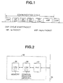
- time division multiplexing is performed on transmitted signals each prescribed communication cycle (for example, 125 msecs) as shown in FIG. 1 of the accompanying drawings.
- This signal transmission commences when an apparatus referred to as a "cycle master” transmits a cycle start packet indicating the start of a communications cycle onto the 1394 bus.
- the two types of communication occurring during one communication cycle are isochronous (hereinafter referred to as "Iso") communication where information signals such as digital video signals and digital audio signals etc. are transmitted in real time and asynchronous (hereinafter referred to as "Async”) communication for transmitting control signals such as operation control commands for apparatus or control commands for connection between apparatus in irregular periods as necessary.
- Iso packets are transmitted before Async packets.
- a plurality of Iso data can then be discriminated between by giving channel numbers 1, 2, 3, ... n to the Iso packets. After the transmission of all of the Iso packets to be transmitted is complete, the period until the next cycle start packet is used for transmitting Async packets.
- a control signal by which a certain apparatus requests something of another apparatus is referred to as a "command" and the side transmitting this command is referred to as a controller, with the side receiving the command being referred to as the target.
- the target responds by sending a control signal (referred to as a "response") indicating command execution results to the controller as necessary.
- a series of exchanges starting with a command transmission and ending with a response are referred to as a command transaction.
- the controller is then capable of requesting specific operations of the target and interrogating the current conditions of the target with command transactions. Any apparatus within the system is capable of starting and ending command transactions with any apparatus being capable of becoming a controller or a target.
- FIGURE 2 is a block view showing the configuration of a portion for carrying out transmission and reception of control signals within each apparatus.
- a physical layer control block (PHY) 31, a link layer control block (LINK) 32 and a CPU 33 are provided within an apparatus 30.
- the physical layer control block carries out arbitration etc. for the initialization of the bus and the priority of use of the bus, as well as carrying out communication with the link layer control block 32 for the various control signals and transmission and reception of these signals to and from the cable of the 1394 serial bus 34.
- the link layer control block 32 carries out packet making/detection and error correction processing.
- the CPU 33 controls the physical layer control block 31 and the link layer control block 32 and carries out processing for the application layers for making the commands and responses etc. When commands and responses are being made, the CPU 33 writes data to prescribed addresses of a register provided within the link layer control block 32. Further, commands and responses transmitted by other apparatus are read by the CPU 33 after being written to a prescribed address of the register.
- the command in a method of transmitting a command to a plurality of electronic apparatus connected by a bus, the command is transmitted to all electronic apparatus connected to the bus using a broadcast communication with a command storage address common to the electronic apparatus being transmitted as an address for storing the command.
- the command in a method of receiving a command transmitted from an electronic apparatus as a controller via a bus, the command is transmitted to all electronic apparatus connected to the bus using a broadcast communication with a command storage address common to all of the electronic apparatus being transmitted in such a manner that the command is stored at the command storage address.
- the command storage address can be stored within a packet header.
- command can be stored in a data field within an Institute of Electrical and Electronic Engineers 1394 format isochronous packet.
- a command for time setting can be used for the command to carry out time setting.
- a command for power supply control can be used as the command to carry out power supply control.
- a prescribed address not used in normal communications can also transmitted or received as the command and a response can be carried out from an electronic apparatus with an address corresponding to the prescribed address.
- the bus can be an Institute of Electrical and Electronic Engineers 1394 serial bus, and the prescribed address can be a node unique identification.
- Information relating to a resource of the bus can also be transmitted or received as the command, and a response is carried out from a corresponding electronic apparatus taking possession of the resource.
- an electronic apparatus utilized in a system carrying out communications between a plurality of electronic apparatus connected by a bus comprises a command storage part having an address common to all electronic apparatus connected by the bus.
- the command storage part stores a received command.
- This electronic apparatus may further comprise a timer management part for carrying out time setting based on a command for time setting transmitted as the command.
- This electronic apparatus can also further comprise a control part for carrying out power supply control based on a command for power supply control transmitted as the command.
- This electronic apparatus can be a recording device having a control part carrying out recording mode control based on a command for recording mode transmitted as the command.
- this electronic apparatus can further comprise a storage part for storing a node unique identification, and carry out a response when the node unique identification is coincident with a node unique identification transmitted as the command.
- the electronic apparatus can further comprise a storage part for storing information relating to a resource of the bus transmitted as the command, and carry out a response when the information is coincident with information relating to a resource transmitted as the command.
- a preferred embodiment of the present invention can therefore achieve time setting or state settings at each apparatus with just one communication.
- FIGURE 3 shows the contents of memory (register) provided within the link layer control block 32 or a CPU (Central Processing Unit) 33 within an apparatus to which the present invention may be applied.
- a command register the address of an area (hereinafter referred to as a "command register") storing received commands is fixed at 512 bytes from "FFFF F000 0B00h” to "FFF F000 0D00h”.
- an address of an area hereinafter referred to as a "response register” storing received -responses is fixed at 512 bytes from "FFFF F000 ODOOh” to "FFFF F000 0DF0h”.
- These addresses are shared by all of the apparatus connected using the 1394 bus.
- Other regions for example, bus dependent regions, are regions characteristic to the IEEE 1394 standard. However, the regions are those decided by this standard and a description of these other regions is therefore omitted.
- FIGURE 4 shows an example of a format for Async packets used in the present invention.
- This packet is a broadcast packet unilaterally transmitted to all of the apparatus capable of receiving this broadcast packet connected by the 1394 bus. Namely, it is shown that "3Fh" of the 1394 Async packet header is a packet destined for all apparatus. Further, by making an FCP (Function Control Protocol) destination offset value for the 1394 Async packet header the beginning address of the command register shown in FIG. 3, this packet is shown to be a command.
- FCP Federal Control Protocol
- a command set type is shown at the CTS (Command Transaction Set) present at the head of the data field.
- CTS Common Transaction Set
- CT/RC Command Type/Response Code
- HA Header Address
- OPC Operaation Code
- OPR Operand
- FIGURE 5 shows a method of controlling other apparatus using the broadcast command of FIG. 4.
- apparatus 1 sends a command packet with the format shown in FIG. 2.
- the source ID of the 1394 Async packet header is #2.
- Other apparatus connected to the 1394 bus, i.e. the apparatus 1, 3 and 4 know that this packet is a broadcast packet by recognizing "3Fh" of the 1394 Async packet header.
- the FCP destination offset value is recognized and it is known that the data for this packet is a command
- this command is written to the command register.
- the command written to the command register is then read out by the CPU within the apparatus and processing is executed in response to this command.
- FIGURE 6 shows an example of an AV communication system to which the present invention is applied.
- This system comprises a television receiver (hereinafter referred to as "TV") 11, a Video Tape Recorder (hereinafter referred to as "VTR") 12, a tuner 13 and a Laser Disc Player (hereinafter referred to as an "LD player”) 14 connected together by 1394 bus cables 15 to 17.
- TV television receiver
- VTR Video Tape Recorder
- LD player Laser Disc Player
- FIGURES 7A to 7F show an example of a command used in the system shown in FIG. 6.
- FIG. 7A is a command format, with "Oh" of the CTS indicating the presence of an AV/C (audio/video controller) command set conforming to 1394 bus protocol.
- AV/C audio/video controller
- FIGURE 7B shows a time adjusted command.
- this command is sent to the 1394 bus by any of the TV 11, VTR 12, tuner 13 or LD player 14 using the broadcast packet shown in FIG. 4, this command is taken in by all of the apparatus on the 1394 bus and time setting is carried out at each apparatus, so that the time at all the apparatus coincides.
- the tuner 13 is equipped with a function for carrying out time setting itself using a time signal from a television broadcast
- a time setting command can be transmitted with a broadcast packet directly after the tuner 13 has carried out time setting by itself using this function.
- this personal computer can be configured so as to periodically transmit a time setting command using broadcast packets.
- a configuration can also be adopted where time setting is carried out when new apparatus are added to the 1394 bus.
- FIGURE 7C shows a power on command.
- This command causes the power supply mode of an apparatus receiving this command to go from a standby state to an on state.
- the standby state is a state corresponding to the receiving of commands.
- any of the TV 11, VTR 12, tuner 13 or LD player 14 send this command to the 1394 bus using the kind of broadcast packet shown in FIG. 4, this command is taken in by all of the apparatus on the 1394 bus and the power supply mode of all apparatus is automatically put to on simultaneously.
- the power off command shown in FIG. 7D contrary to the power on command, causes the power supply mode of apparatus receiving this command to transfer from an on state to a standby state.
- FIGURE 7E shows a playback command.
- This command is a command setting the VTR in a forward direction playback mode.
- a plurality of the VTRs are simultaneously set in playback mode.
- FIG. 7F shows an example of a command for setting the recording speed of the VTR, particularly, for setting the VTR in normal recording mode.
- this command is sent using a broadcast packet in a system where a plurality of the VTRs are connected on a 1394 bus, a plurality of the VTRs are simultaneously set in normal recording mode.
- FIGURE 8 is a block diagram showing a configuration of a VTR connected to the 1394 bus.
- the communications interface 23 shown in FIG. 8 corresponds to the physical layer control block 31 and the link layer control block 32 shown in FIG. 2.
- a digital interface microcomputer 24 corresponds to the CPU 33.
- a mode processing microcomputer 25 carries out control etc. of all of the operating modes of the VTR 21.
- a timer management microcomputer 26 then controls a timer display 27.
- a mechanical control microcomputer 28 controls a mechanical system 29 as well as power supplies.
- a block is provided for processing audio and video signals, but as this bears no direct relationship to command communication, a description of this is omitted here.
- other apparatus such as a television or tuner etc. connected to the 1394 bus are also provided with the basic configuration including the timer management microcomputer 26 and the mechanical control microcomputer 28 with the power supply control function etc.
- a packet on the 1394 bus 22 is inputted to the communications interface 23, with a command then being extracted and stored in the aforementioned command register within the link layer control block 32.
- the digital interface microcomputer 24 then reads out the command from the command register and sends this command to the mode processing microcomputer 25, which then executes processing in response to this command, i.e., in the case of a time setting command the timer management microcomputer 26 carries out processing so as to control the timer display 27.
- the mechanical control microcomputer 28 is put off in the case of a power off command and on in the case of a power on command. Further, in the case of a playback or record command, the mechanical control microcomputer 28 and an audio/video signal processing block not shown in the drawings are controlled so that playback or recording is carried out.
- FIGURE 9 shows the procedure while confirming power supply states in the system shown in FIG. 6 after the TV has sent a power off command to all of the other apparatus and FIG. 10 shows the command and response formats used in this procedure.
- the encircled numbers 1 to 7 of FIG. 9 correspond to those 1 to 7 of FIG. 10, respectively.
- the TV 11 sends the power command shown in FIG. 10A using a broadcast packet in order to put the VTR 12, tuner 13 and LD player 14 in standby. Each apparatus then receives this command and decides whether or not to execute this command in accordance with its own specifications.
- the TV 11 then sends a status command shown in FIG. 10B to the VTR 12 in order to ascertain the state of its power supply.
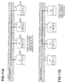
- FIGURE 11 shows a method for investigating the physical address of other apparatus with known node unique IDs using the broadcast command of FIG. 4.
- four apparatus 1, 2, 3 and 4 are connected using a 1394 bus, with the physical addresses on the 1394 bus of the apparatus 1, 2, 3 and 4 being #1, #2, #3 and #4, respectively.
- the respective node unique IDs of the apparatus 1, 2, 3 and 4 are "YYY-1", "XXX-13", “XXX-15” and "YYY-7".
- a node unique ID is a unique ID given to apparatus used in being connected to the 1394 bus and comprises a company ID and serial number. Company IDs are allotted to vendors of apparatus by the IEEE and serial numbers are allotted to the apparatus by each vendor. These node unique IDs are written beforehand to ROMs within each apparatus and do not change even when the 1394 bus is reset. Contrary to this, however, a physical address may be changed when the 1394 bus is reset.
- FIGs. 12A to 12C The command and response formats used in the way shown in FIGs. 11A and 11B are shown in FIGs. 12A to 12C.
- the apparatus 2 sends a command to require notification of the physical address of apparatus having a node unique ID of "YYY-7" to the apparatus 1, 3 and 4 connected using the 1394 serial bus. This is achieved by sending the command shown in FIG. 12A to the 1394 bus using the broadcast packet shown in FIG. 4.
- the node unique IDs in OPR 1 to 8 of FIG. 12A comprise a three byte company ID and a five byte serial number, as shown in FIG. 12C.
- the apparatus 1, 3 and 4 then receive this command and compare this command with a node unique ID stored within a ROM of each apparatus.
- apparatus having a node unique ID coincident with the received node unique ID that is, the apparatus having a node unique ID of "YYY-7" as shown in FIG. 11B, i.e. the apparatus 4, responds to the apparatus 2 in such a manner as to give notice that its own physical address is #4.
- the response format used at this time is shown in FIG. 12B.
- the apparatus outputting the Iso packet to the designated channel, on detecting the reception of the interrogation with the broadcast, then responds to the controller that is the transmission source with information relating to the resources of the apparatus itself, so that the controller can identify the apparatus.
- a command shown in FIG. 13A is for making interrogations regarding the physical address (including the bus ID and the PHY_ID), the number of the logical plug outputting the packet and how much of the band width of the 1394 bus is being used.
- the apparatus receiving this command is using channel number 3, the apparatus sends back a stable response with interrogated parameters as shown in FIG. 13B.
- Information relating to such resources (the aforementioned channel number, physical address, logical plug number and band width etc.) is stored in a predetermined storage and its coincidence with a command is detected by carrying out comparisons with the contents of the aforementioned command. In this way, by designating information relating to the resources, the apparatus acquiring the information can be identified.
- control of time setting and the setting states of power supply etc. can be realized with a one-time communication for a plurality of apparatus connected to a bus. Further, by designating addresses not used in normal communications, such as node unique addresses of the 1394 bus and information relating to bus resources, and adopting a configuration where only apparatus having these designated addresses or information relating to the bus resources respond, apparatus having these designated addresses and apparatus acquiring information relating to the designated bus resources can be investigated.
Landscapes
- Engineering & Computer Science (AREA)
- Computer Networks & Wireless Communication (AREA)
- Signal Processing (AREA)
- Automation & Control Theory (AREA)
- Multimedia (AREA)
- Small-Scale Networks (AREA)
Abstract
In a system for carrying out communication between a plurality of apparatus connected using an IEEE 1394 serial bus etc., command register addresses are fixed from "FFFF F000 0B00h" to "FFFF F000 0D00h" and response register addresses are fixed from "FFFF F000 0D00h" to "FFFF F000 0DF0h". These addresses are then common to all of the apparatus connected to the bus. Then, while an arbitrary apparatus on the bus is sending a command to all of the remaining apparatus, the address of the command register is included in the command and this command is transmitted as a broadcast communication. This command is then stored at a command register having a common address within the apparatus that received the command. Thus, time setting and state setting etc. of each apparatus can be achieved.
Description
- The present invention relates to a system for carrying out communication between a plurality of electronic apparatus with the electronic apparatus being connected, for example, using an IEEE 1394 serial bus.
- A system has been considered where a plurality of electronic apparatus (hereinafter referred to as "apparatus") are connected together by a bus such as an IEEE 1394 serial bus (hereinafter referred to as a "1394 bus") which is capable of transmitting information signal packets and control signal packets with these packets mixed together and communication is then carried out between these apparatus.
- In this system, time division multiplexing is performed on transmitted signals each prescribed communication cycle (for example, 125 msecs) as shown in FIG. 1 of the accompanying drawings. This signal transmission commences when an apparatus referred to as a "cycle master" transmits a cycle start packet indicating the start of a communications cycle onto the 1394 bus. The two types of communication occurring during one communication cycle are isochronous (hereinafter referred to as "Iso") communication where information signals such as digital video signals and digital audio signals etc. are transmitted in real time and asynchronous (hereinafter referred to as "Async") communication for transmitting control signals such as operation control commands for apparatus or control commands for connection between apparatus in irregular periods as necessary. Here, Iso packets are transmitted before Async packets. A plurality of Iso data can then be discriminated between by giving
channel numbers - In Async communications, a control signal by which a certain apparatus requests something of another apparatus is referred to as a "command" and the side transmitting this command is referred to as a controller, with the side receiving the command being referred to as the target. The target then responds by sending a control signal (referred to as a "response") indicating command execution results to the controller as necessary. A series of exchanges starting with a command transmission and ending with a response are referred to as a command transaction. The controller is then capable of requesting specific operations of the target and interrogating the current conditions of the target with command transactions. Any apparatus within the system is capable of starting and ending command transactions with any apparatus being capable of becoming a controller or a target.
- FIGURE 2 is a block view showing the configuration of a portion for carrying out transmission and reception of control signals within each apparatus. A physical layer control block (PHY) 31, a link layer control block (LINK) 32 and a
CPU 33 are provided within anapparatus 30. The physical layer control block carries out arbitration etc. for the initialization of the bus and the priority of use of the bus, as well as carrying out communication with the linklayer control block 32 for the various control signals and transmission and reception of these signals to and from the cable of the 1394serial bus 34. The linklayer control block 32 carries out packet making/detection and error correction processing. TheCPU 33 controls the physicallayer control block 31 and the linklayer control block 32 and carries out processing for the application layers for making the commands and responses etc. When commands and responses are being made, theCPU 33 writes data to prescribed addresses of a register provided within the linklayer control block 32. Further, commands and responses transmitted by other apparatus are read by theCPU 33 after being written to a prescribed address of the register. - With the above system it has been necessary for the clocks within the apparatus to be set to the same time for each apparatus regardless of whether or not the apparatus is connected to the 1394 bus and there has been no means for accurately setting the clock of each apparatus connected to the same 1394 bus to the same time.
- Further, in the above described system, in order for a certain apparatus to set all of the other apparatus at standby condition, it has been necessary to transmit an individual and separate command from a certain apparatus to each other apparatus.
- According to one aspect of the invention, in a method of transmitting a command to a plurality of electronic apparatus connected by a bus, the command is transmitted to all electronic apparatus connected to the bus using a broadcast communication with a command storage address common to the electronic apparatus being transmitted as an address for storing the command.
- According to another aspect of the invention, in a method of receiving a command transmitted from an electronic apparatus as a controller via a bus, the command is transmitted to all electronic apparatus connected to the bus using a broadcast communication with a command storage address common to all of the electronic apparatus being transmitted in such a manner that the command is stored at the command storage address.
- In the above methods, the command storage address can be stored within a packet header.
- Further, the command can be stored in a data field within an Institute of Electrical and Electronic Engineers 1394 format isochronous packet.
- A command for time setting can be used for the command to carry out time setting. Alternatively, a command for power supply control can be used as the command to carry out power supply control.
- A prescribed address not used in normal communications can also transmitted or received as the command and a response can be carried out from an electronic apparatus with an address corresponding to the prescribed address.
- Here, the bus can be an Institute of Electrical and Electronic Engineers 1394 serial bus, and the prescribed address can be a node unique identification.
- Information relating to a resource of the bus can also be transmitted or received as the command, and a response is carried out from a corresponding electronic apparatus taking possession of the resource.
- According to a further aspect of the invention, an electronic apparatus utilized in a system carrying out communications between a plurality of electronic apparatus connected by a bus, comprises a command storage part having an address common to all electronic apparatus connected by the bus. Here, the command storage part stores a received command.
- This electronic apparatus may further comprise a timer management part for carrying out time setting based on a command for time setting transmitted as the command.
- This electronic apparatus can also further comprise a control part for carrying out power supply control based on a command for power supply control transmitted as the command.
- This electronic apparatus can be a recording device having a control part carrying out recording mode control based on a command for recording mode transmitted as the command.
- Moreover, this electronic apparatus can further comprise a storage part for storing a node unique identification, and carry out a response when the node unique identification is coincident with a node unique identification transmitted as the command.
- Still further, the electronic apparatus can further comprise a storage part for storing information relating to a resource of the bus transmitted as the command, and carry out a response when the information is coincident with information relating to a resource transmitted as the command.
- A preferred embodiment of the present invention can therefore achieve time setting or state settings at each apparatus with just one communication.
- The invention will now be described by way of example with reference to the accompanying drawings, throughout which like parts are referred to by like references, and in which:
- FIG. 1 is a view showing an example of signal transmission at apparatus connected to a 1394 bus;
- FIG. 2 is a block diagram showing the configuration of portions for carrying out transmission and reception of control signals within apparatus connected to the 1394 bus;
- FIG. 3 is a view showing contents of a memory provided within a link layer control block within apparatus to which the present invention may be applied;
- FIG. 4 is a view showing an example of an Async packet format used in an embodiment of the present invention;
- FIG. 5 is a view showing a method of controlling other apparatus using the broadcast command of FIG. 4;
- FIG. 6 is a view showing an example of an Audio Visual (hereinafter abbreviated to "AV") communication system to which the present invention may be applied;
- FIG. 7 is a view showing an example of commands used in the system shown in FIG. 6;
- FIG. 8 is a block diagram showing the configuration of a VTR connected to a 1394 bus;
- FIG. 9 is a view showing the procedure during confirmation of states of power supply after the TV has sent power off commands to all of the other apparatus in the system shown in FIG. 6;
- FIG. 10 is a view showing command and response formats used in the procedure of FIG. 9;
- FIG. 11 is a view showing a method of investigating the physical addresses of other apparatus with the known node unique ID using the broadcast command of FIG. 4;
- FIG. 12 is a view showing the command and response formats used in the method shown in FIG. 11; and
- FIG. 13 is a view showing command and response formats used while searching for apparatus for which the channel number is known that are outputting Iso packets.
- FIGURE 3 shows the contents of memory (register) provided within the link
layer control block 32 or a CPU (Central Processing Unit) 33 within an apparatus to which the present invention may be applied. Here, the address of an area (hereinafter referred to as a "command register") storing received commands is fixed at 512 bytes from "FFFF F000 0B00h" to "FFF F000 0D00h". Further, an address of an area (hereinafter referred to as a "response register") storing received -responses is fixed at 512 bytes from "FFFF F000 ODOOh" to "FFFF F000 0DF0h". These addresses are shared by all of the apparatus connected using the 1394 bus. Other regions, for example, bus dependent regions, are regions characteristic to the IEEE 1394 standard. However, the regions are those decided by this standard and a description of these other regions is therefore omitted. - FIGURE 4 shows an example of a format for Async packets used in the present invention. This packet is a broadcast packet unilaterally transmitted to all of the apparatus capable of receiving this broadcast packet connected by the 1394 bus. Namely, it is shown that "3Fh" of the 1394 Async packet header is a packet destined for all apparatus. Further, by making an FCP (Function Control Protocol) destination offset value for the 1394 Async packet header the beginning address of the command register shown in FIG. 3, this packet is shown to be a command.
- In FIG. 4, a command set type is shown at the CTS (Command Transaction Set) present at the head of the data field. Here, CT/RC (Command Type/Response Code) shows a request type for a command and shows a response type for a response. Further, HA (Header Address) shows the address in the case of a command and shows the sending source in the case of a response. A command and parameters thereof are then shown with an OPC (Operation Code) and an OPR (Operand).
- FIGURE 5 shows a method of controlling other apparatus using the broadcast command of FIG. 4. Here, four
apparatus apparatus apparatus 2 sends a command packet with the format shown in FIG. 2. At this time, the source ID of the 1394 Async packet header is #2. Other apparatus connected to the 1394 bus, i.e. theapparatus - FIGURE 6 shows an example of an AV communication system to which the present invention is applied. This system comprises a television receiver (hereinafter referred to as "TV") 11, a Video Tape Recorder (hereinafter referred to as "VTR") 12, a
tuner 13 and a Laser Disc Player (hereinafter referred to as an "LD player") 14 connected together by 1394bus cables 15 to 17. Each apparatus in this system is equipped with control signal processing blocks such as shown in FIG. 2, with the memory shown in FIG. 3 being provided at a control register within the link layer control block. - FIGURES 7A to 7F show an example of a command used in the system shown in FIG. 6. Here, FIG. 7A is a command format, with "Oh" of the CTS indicating the presence of an AV/C (audio/video controller) command set conforming to 1394 bus protocol.
- FIGURE 7B shows a time adjusted command. When this command is sent to the 1394 bus by any of the
TV 11,VTR 12,tuner 13 orLD player 14 using the broadcast packet shown in FIG. 4, this command is taken in by all of the apparatus on the 1394 bus and time setting is carried out at each apparatus, so that the time at all the apparatus coincides. For example, when thetuner 13 is equipped with a function for carrying out time setting itself using a time signal from a television broadcast, a time setting command can be transmitted with a broadcast packet directly after thetuner 13 has carried out time setting by itself using this function. Further, by adding a personal computer to the system of FIG. 6, this personal computer can be configured so as to periodically transmit a time setting command using broadcast packets. A configuration can also be adopted where time setting is carried out when new apparatus are added to the 1394 bus. - FIGURE 7C shows a power on command. This command causes the power supply mode of an apparatus receiving this command to go from a standby state to an on state. The standby state is a state corresponding to the receiving of commands. When any of the
TV 11,VTR 12,tuner 13 orLD player 14 send this command to the 1394 bus using the kind of broadcast packet shown in FIG. 4, this command is taken in by all of the apparatus on the 1394 bus and the power supply mode of all apparatus is automatically put to on simultaneously. The power off command shown in FIG. 7D; contrary to the power on command, causes the power supply mode of apparatus receiving this command to transfer from an on state to a standby state. - FIGURE 7E shows a playback command. This command is a command setting the VTR in a forward direction playback mode. When this command is sent using a broadcast packet in a system where a plurality of VTRs are connected on a 1394 bus, a plurality of the VTRs are simultaneously set in playback mode. Further, FIG. 7F shows an example of a command for setting the recording speed of the VTR, particularly, for setting the VTR in normal recording mode. When this command is sent using a broadcast packet in a system where a plurality of the VTRs are connected on a 1394 bus, a plurality of the VTRs are simultaneously set in normal recording mode.
- FIGURE 8 is a block diagram showing a configuration of a VTR connected to the 1394 bus. The
communications interface 23 shown in FIG. 8 corresponds to the physicallayer control block 31 and the linklayer control block 32 shown in FIG. 2. Adigital interface microcomputer 24 corresponds to theCPU 33. Amode processing microcomputer 25 carries out control etc. of all of the operating modes of theVTR 21. Atimer management microcomputer 26 then controls atimer display 27. Amechanical control microcomputer 28 controls amechanical system 29 as well as power supplies. In an actual VTR a block is provided for processing audio and video signals, but as this bears no direct relationship to command communication, a description of this is omitted here. Although not shown in the drawings, other apparatus such as a television or tuner etc. connected to the 1394 bus are also provided with the basic configuration including thetimer management microcomputer 26 and themechanical control microcomputer 28 with the power supply control function etc. - Next, the operation when the VTR of FIG. 8 received the command shown in FIG. 7 is described. A packet on the 1394
bus 22 is inputted to thecommunications interface 23, with a command then being extracted and stored in the aforementioned command register within the linklayer control block 32. Thedigital interface microcomputer 24 then reads out the command from the command register and sends this command to themode processing microcomputer 25, which then executes processing in response to this command, i.e., in the case of a time setting command thetimer management microcomputer 26 carries out processing so as to control thetimer display 27. Themechanical control microcomputer 28 is put off in the case of a power off command and on in the case of a power on command. Further, in the case of a playback or record command, themechanical control microcomputer 28 and an audio/video signal processing block not shown in the drawings are controlled so that playback or recording is carried out. - FIGURE 9 shows the procedure while confirming power supply states in the system shown in FIG. 6 after the TV has sent a power off command to all of the other apparatus and FIG. 10 shows the command and response formats used in this procedure. Here, the encircled
numbers 1 to 7 of FIG. 9 correspond to those 1 to 7 of FIG. 10, respectively. First, theTV 11 sends the power command shown in FIG. 10A using a broadcast packet in order to put theVTR 12,tuner 13 andLD player 14 in standby. Each apparatus then receives this command and decides whether or not to execute this command in accordance with its own specifications. TheTV 11 then sends a status command shown in FIG. 10B to theVTR 12 in order to ascertain the state of its power supply. At this time, "3Fh" indicating a broadcast packet in the 1394 Async packet header is substituted by the physical address of theVTR 12 on the 1394 bus. In addition, a prescribed numerical value (FF) has been stored at the parameter region for securing the storing region for the response data (in this case, on or off). TheVTR 12, on receiving this command, sends a stable response showing that the power supply is off as shown in FIG. 10C to theTV 11. By recognizing this response, theTV 11 can then confirm whether or not theVTR 12 is in standby. TheTV 11 then carries out communications with the command and response shown in FIG. 10D to FIG. 10F between thetuner 13 and theLD player 14 so as to confirm whether or not these apparatus are in standby. Here, the case is, shown where all apparatus have made the transition to standby. However, it is possible to carry out processing in accordance with the specifications of each apparatus such that, in the case of a VTR, a transition to standby will not be made upon the reception of a power off command during recording, or, in the case of a personal computer, a power off command cannot be accepted. Here, confirmation of the states of power supply has been performed in the order of VTR, tuner and then LD player but this may be carried out in arbitrary order. - FIGURE 11 shows a method for investigating the physical address of other apparatus with known node unique IDs using the broadcast command of FIG. 4. Here, four
apparatus apparatus apparatus - The command and response formats used in the way shown in FIGs. 11A and 11B are shown in FIGs. 12A to 12C. As shown in FIG. 11A, the
apparatus 2 sends a command to require notification of the physical address of apparatus having a node unique ID of "YYY-7" to theapparatus OPR 1 to 8 of FIG. 12A comprise a three byte company ID and a five byte serial number, as shown in FIG. 12C. Theapparatus apparatus 4, responds to theapparatus 2 in such a manner as to give notice that its own physical address is #4. The response format used at this time is shown in FIG. 12B. - As described above, when a bus reset occurs for a reason such as new apparatus being added to the 1394 bus, physical addresses are re-allotted to cause possible change in the physical addresses of each apparatus. Because of this, when an apparatus with the known physical address outputs an Iso packet to the 1394 bus before a bus reset, this apparatus becomes unknown after the bus reset. At this time, as a method of finding this apparatus, information relating to the resources of the bus is utilized. In this method, a command is transmitted from an apparatus designated as a controller to each apparatus connected to the 1394 bus with the number of the channel to which an Iso packet is outputted being designated and information relating to the apparatus outputting the Iso packet to the designated channel is interrogated with a broadcast. The apparatus outputting the Iso packet to the designated channel, on detecting the reception of the interrogation with the broadcast, then responds to the controller that is the transmission source with information relating to the resources of the apparatus itself, so that the controller can identify the apparatus. For example, a command shown in FIG. 13A is for making interrogations regarding the physical address (including the bus ID and the PHY_ID), the number of the logical plug outputting the packet and how much of the band width of the 1394 bus is being used. When the apparatus receiving this command is using
channel number 3, the apparatus sends back a stable response with interrogated parameters as shown in FIG. 13B. Information relating to such resources (the aforementioned channel number, physical address, logical plug number and band width etc.) is stored in a predetermined storage and its coincidence with a command is detected by carrying out comparisons with the contents of the aforementioned command. In this way, by designating information relating to the resources, the apparatus acquiring the information can be identified. - In the above, a description was given of a system where a plurality of apparatus were connected using a 1394 bus. However, the present invention can also be used to investigate physical addresses for other buses by using broadcast commands and designating apparatus addresses that are not used in normal communications. A target apparatus can also be searched for by designating information relating to the bus resource.
- As described above, control of time setting and the setting states of power supply etc. can be realized with a one-time communication for a plurality of apparatus connected to a bus. Further, by designating addresses not used in normal communications, such as node unique addresses of the 1394 bus and information relating to bus resources, and adopting a configuration where only apparatus having these designated addresses or information relating to the bus resources respond, apparatus having these designated addresses and apparatus acquiring information relating to the designated bus resources can be investigated.
Claims (22)
- In a method of transmitting a command to a plurality of electronic apparatus connected by a bus, the improvement wherein said command is transmitted to all electronic apparatus connected to said bus using a broadcast communication with a command storage address common to said electronic apparatus being transmitted as an address for storing said command.
- The method of claim 1, wherein said command storage address is transmitted with said command being stored within a packet header address.
- The method of claim 1, wherein said command is transmitted with said command being stored in a data field within an Institute of Electrical and Electronic Engineers 1394 format isochronous packet.
- The method of claim 1, wherein a command for time setting is transmitted as said command to carry out time setting for each electronic apparatus on a receiving side.
- The method of claim 1, wherein a command for power supply control is transmitted as said command to control power supplies for each electronic apparatus on a receiving side.
- The method of claim 1, wherein a prescribed address not used in normal communications is transmitted as said command, and a reply is received from an electronic apparatus having'said prescribed address.
- The method of claim 6, wherein said bus is an Institute of Electrical and Electronic Engineers 1394 serial bus, and said prescribed address is a node unique identification.
- The method of claim 1, wherein information relating to a resource of said bus is transmitted as said command, and reply is received from an electronic apparatus taking possession of said resource.
- In a method of receiving a command transmitted from an electronic apparatus as a controller via a bus, the improvement wherein said command is transmitted to all electronic apparatus connected to said bus using a broadcast communication with a command storage address common to all of said electronic apparatus being transmitted in such a manner that said command is stored at said command storage address.
- The method of claim 9, wherein said command storage address is received with said command being stored within a packet header.
- The method of claim 9, wherein said command is received with said command being stored in a data field within an Institute of Electrical and Electronic Engineers 1394 format isochronous packet.
- The method of claim 9, wherein a command for time setting is received as said command and time setting is carried out.
- The method of claim 9, wherein a command for power supply control is received as said command and power supplies are controlled.
- The method of claim 9, wherein a prescribed address not used in normal communications is received as said command, and a response is carried out from an electronic apparatus with an address corresponding to said prescribed address.
- The method of claim 14, wherein said bus is an Institute of Electrical and Electronic Engineers 1394 serial bus, and said prescribed address is a node unique identification.
- The method of claim 9, wherein information relating to a resource of said bus is received as said command, and a response is carried out from an electronic apparatus taking possession of said resource.
- An electronic apparatus utilized in a system carrying out communications between a plurality of electronic apparatus connected by a bus, comprising:command storage means having an address common to all electronic apparatus connected by said bus,said command storage means storing a received command.
- The electronic apparatus of claim 17, further comprising a timer management part for carrying out time setting based on a command for time setting transmitted as said command.
- The electronic apparatus of claim 17, further comprising a control part for carrying out power supply control based on a command for power supply control transmitted as said command.
- The electronic apparatus of claim 17, wherein said electronic apparatus is a recording device having a control part carrying out recording mode control based on a command for recording mode transmitted as said command.
- The electronic apparatus of claim 17, further comprising a storage part for storing a node unique identification, and carrying out a response when said node unique identification is coincident with a node unique identification transmitted as said command.
- The electronic apparatus of claim 17, further comprising a storage part for storing information relating to a resource of said bus transmitted as said command, and carrying out a response when said information is coincident with information relating to a resource transmitted as said command.
Applications Claiming Priority (2)
| Application Number | Priority Date | Filing Date | Title |
|---|---|---|---|
| JP315558/96 | 1996-11-12 | ||
| JP31555896 | 1996-11-12 |
Publications (1)
| Publication Number | Publication Date |
|---|---|
| EP0841776A1 true EP0841776A1 (en) | 1998-05-13 |
Family
ID=18066799
Family Applications (1)
| Application Number | Title | Priority Date | Filing Date |
|---|---|---|---|
| EP97309053A Withdrawn EP0841776A1 (en) | 1996-11-12 | 1997-11-11 | Communication methods and electronic apparatus thereof |
Country Status (4)
| Country | Link |
|---|---|
| US (1) | US6108718A (en) |
| EP (1) | EP0841776A1 (en) |
| KR (1) | KR19980042496A (en) |
| CN (1) | CN1190834A (en) |
Cited By (16)
| Publication number | Priority date | Publication date | Assignee | Title |
|---|---|---|---|---|
| EP0905974A2 (en) * | 1997-09-25 | 1999-03-31 | Victor Company of Japan, Ltd. | Interactive data transmission system including information recording and/or reproduction apparatus connected to an electronic control apparatus via a bus |
| EP1024493A2 (en) * | 1999-01-27 | 2000-08-02 | Sony Corporation | Digital signal transmission, computer program product, and recording medium |
| WO2000062487A1 (en) * | 1999-04-09 | 2000-10-19 | Sony Corporation | Information processing device and method, and information processing system, and recorded medium |
| EP1085770A1 (en) * | 1999-04-02 | 2001-03-21 | Sony Corporation | Electronic device and its repairing method |
| WO2001030027A1 (en) * | 1999-10-22 | 2001-04-26 | Hitachi, Ltd. | Information device having time correcting function and clock correcting method |
| EP1116230A1 (en) * | 1999-07-27 | 2001-07-18 | Samsung Electronics Co., Ltd. | Device discovery and configuration in a home network |
| EP1128562A2 (en) * | 2000-02-22 | 2001-08-29 | Sony Corporation | Controlling apparatus and controlling method |
| EP1132817A1 (en) * | 1998-07-31 | 2001-09-12 | Matsushita Electric Industrial Co., Ltd. | Connection-confirmable information processing system, connection-confirmable information processing apparatus, information processing method by which connection is confirmable, recorder, recording system, recording method, method for recognizing correspondence between node and terminal, computer, te |
| US6378000B1 (en) | 1999-04-29 | 2002-04-23 | Mitsubish Electric Research Laboratories, Inc | Address mapping in home entertainment network |
| EP1229691A2 (en) | 2001-02-05 | 2002-08-07 | Samsung Electronics Co., Ltd. | Setting environment parameters in portable devices |
| US6496862B1 (en) | 1998-08-25 | 2002-12-17 | Mitsubishi Electric Research Laboratories, Inc. | Remote monitoring and control of devices connected to an IEEE 1394 bus via a gateway device |
| US6505255B1 (en) | 1999-04-29 | 2003-01-07 | Mitsubishi Electric Information Technology Center America, Inc. (Ita) | Method for formatting and routing data between an external network and an internal network |
| US6523064B1 (en) | 1999-04-29 | 2003-02-18 | Mitsubishi Electric Research Laboratories, Inc | Network gateway for collecting geographic data information |
| US6633547B1 (en) | 1999-04-29 | 2003-10-14 | Mitsubishi Electric Research Laboratories, Inc. | Command and control transfer |
| EP1395007A1 (en) * | 2002-08-29 | 2004-03-03 | Yamaha Corporation | Command synchronization establishment system |
| EP1507210A3 (en) * | 2003-08-09 | 2006-03-29 | Samsung Electronics Co., Ltd. | Method and system for controlling peripheral devices connected to a video device |
Families Citing this family (19)
| Publication number | Priority date | Publication date | Assignee | Title |
|---|---|---|---|---|
| US6272546B1 (en) | 1998-03-12 | 2001-08-07 | Sony Corporation | Method of and apparatus for managing resource allocation and bandwidth overflow in a cooperative, distributed computing environment |
| JP3489440B2 (en) * | 1998-05-26 | 2004-01-19 | 松下電器産業株式会社 | Data transmission / reception method |
| US6891797B1 (en) * | 1998-07-06 | 2005-05-10 | Canon Kabushiki Kaisha | Method and device for communicating information |
| US6304914B1 (en) | 1998-09-22 | 2001-10-16 | Microsoft Corporation | Method and apparatus for pre-compression packaging |
| US6539450B1 (en) | 1998-11-29 | 2003-03-25 | Sony Corporation | Method and system for adjusting isochronous bandwidths on a bus |
| US6687260B1 (en) * | 1999-02-12 | 2004-02-03 | Conexant Systems, Inc. | Apparatus and methods for flow control of non-isochronous data |
| US6374316B1 (en) | 1999-03-19 | 2002-04-16 | Sony Corporation | Method and system for circumscribing a topology to form ring structures |
| US6631415B1 (en) | 1999-03-19 | 2003-10-07 | Sony Corporation | Method and system for providing a communication connection using stream identifiers |
| US6810452B1 (en) | 1999-03-19 | 2004-10-26 | Sony Corporation | Method and system for quarantine during bus topology configuration |
| US6502158B1 (en) | 1999-04-23 | 2002-12-31 | Sony Corporation | Method and system for address spaces |
| JP3539287B2 (en) * | 1999-07-15 | 2004-07-07 | セイコーエプソン株式会社 | Data transfer control device and electronic equipment |
| KR100662484B1 (en) * | 1999-08-23 | 2007-01-02 | 엘지전자 주식회사 | method for controlling bus in digital interface |
| US6728821B1 (en) | 1999-11-29 | 2004-04-27 | Sony Corporation | Method and system for adjusting isochronous bandwidths on a bus |
| US6647446B1 (en) * | 2000-03-18 | 2003-11-11 | Sony Corporation | Method and system for using a new bus identifier resulting from a bus topology change |
| US6757773B1 (en) | 2000-06-30 | 2004-06-29 | Sony Corporation | System and method for determining support capability of a device coupled to a bus system |
| KR100434270B1 (en) * | 2001-05-30 | 2004-06-04 | 엘지전자 주식회사 | Control System for Home Appliance Network |
| US8074250B2 (en) * | 2002-03-26 | 2011-12-06 | Nxp B.V. | High frequency tuner |
| JP3844218B2 (en) * | 2002-04-03 | 2006-11-08 | ソニー株式会社 | Signal processing system, signal input device, and communication control method |
| JP2016063313A (en) * | 2014-09-16 | 2016-04-25 | 株式会社東芝 | Camera system and electronic apparatus |
Citations (3)
| Publication number | Priority date | Publication date | Assignee | Title |
|---|---|---|---|---|
| WO1984003192A1 (en) * | 1983-02-07 | 1984-08-16 | American Telephone & Telegraph | Data network interface |
| EP0315158A2 (en) * | 1987-11-02 | 1989-05-10 | Matsushita Electric Industrial Co., Ltd. | Method and apparatus for controlling terminals on communication network |
| EP0689296A2 (en) * | 1994-06-24 | 1995-12-27 | Sony Corporation | Communication system and electronic apparatus |
Family Cites Families (13)
| Publication number | Priority date | Publication date | Assignee | Title |
|---|---|---|---|---|
| US4777595A (en) * | 1982-05-07 | 1988-10-11 | Digital Equipment Corporation | Apparatus for transferring blocks of information from one node to a second node in a computer network |
| US4601586A (en) * | 1984-02-10 | 1986-07-22 | Prime Computer, Inc. | Solicited message packet transfer system |
| KR920001576B1 (en) * | 1987-09-09 | 1992-02-18 | 가부시끼가이샤 도시바 | Network system using token-passing bus with multiple priority levels |
| US4964038A (en) * | 1987-10-28 | 1990-10-16 | International Business Machines Corp. | Data processing system having automatic address allocation arrangements for addressing interface cards |
| JPH0767111B2 (en) * | 1989-06-23 | 1995-07-19 | アルカテル・エヌ・ブイ | Communications system |
| US5243596A (en) * | 1992-03-18 | 1993-09-07 | Fischer & Porter Company | Network architecture suitable for multicasting and resource locking |
| JP3318635B2 (en) * | 1994-02-24 | 2002-08-26 | ソニー株式会社 | Electronic equipment and communication method |
| DE69531011T2 (en) * | 1994-03-09 | 2004-05-19 | Matsushita Electric Industrial Co., Ltd., Kadoma | Data transmission system and method |
| DE69525556T2 (en) * | 1994-03-21 | 2002-09-12 | Avid Technology Inc | Device and method executed on a computer for real-time multimedia data transmission in a distributed computer arrangement |
| KR0150984B1 (en) * | 1994-04-07 | 1998-11-02 | 김광호 | Home data bus control system |
| JP3520572B2 (en) * | 1994-08-02 | 2004-04-19 | ソニー株式会社 | Input device selection method |
| JP3561969B2 (en) * | 1994-08-30 | 2004-09-08 | ソニー株式会社 | Editing method and editing control device |
| US5600310A (en) * | 1994-12-02 | 1997-02-04 | General Electric Company | Serial bus control for appliances |
-
1997
- 1997-11-11 EP EP97309053A patent/EP0841776A1/en not_active Withdrawn
- 1997-11-12 KR KR1019970060394A patent/KR19980042496A/en active IP Right Grant
- 1997-11-12 US US08/968,357 patent/US6108718A/en not_active Expired - Fee Related
- 1997-11-12 CN CN97114367A patent/CN1190834A/en active Pending
Patent Citations (3)
| Publication number | Priority date | Publication date | Assignee | Title |
|---|---|---|---|---|
| WO1984003192A1 (en) * | 1983-02-07 | 1984-08-16 | American Telephone & Telegraph | Data network interface |
| EP0315158A2 (en) * | 1987-11-02 | 1989-05-10 | Matsushita Electric Industrial Co., Ltd. | Method and apparatus for controlling terminals on communication network |
| EP0689296A2 (en) * | 1994-06-24 | 1995-12-27 | Sony Corporation | Communication system and electronic apparatus |
Cited By (36)
| Publication number | Priority date | Publication date | Assignee | Title |
|---|---|---|---|---|
| EP0905974A3 (en) * | 1997-09-25 | 2000-08-23 | Victor Company of Japan, Ltd. | Interactive data transmission system including information recording and/or reproduction apparatus connected to an electronic control apparatus via a bus |
| EP0905974A2 (en) * | 1997-09-25 | 1999-03-31 | Victor Company of Japan, Ltd. | Interactive data transmission system including information recording and/or reproduction apparatus connected to an electronic control apparatus via a bus |
| US6292846B1 (en) | 1997-09-25 | 2001-09-18 | Victor Company Of Japan, Ltd. | Interactive data transmission system including information recording and/or reproduction apparatus connected to an electronic control apparatus via a bus |
| EP1132817A1 (en) * | 1998-07-31 | 2001-09-12 | Matsushita Electric Industrial Co., Ltd. | Connection-confirmable information processing system, connection-confirmable information processing apparatus, information processing method by which connection is confirmable, recorder, recording system, recording method, method for recognizing correspondence between node and terminal, computer, te |
| EP1132817A4 (en) * | 1998-07-31 | 2008-01-02 | Matsushita Electric Ind Co Ltd | Connection-confirmable information processing system, connection-confirmable information processing apparatus, information processing method by which connection is confirmable, recorder, recording system, recording method, method for recognizing correspondence between node and terminal, computer, te |
| US6496862B1 (en) | 1998-08-25 | 2002-12-17 | Mitsubishi Electric Research Laboratories, Inc. | Remote monitoring and control of devices connected to an IEEE 1394 bus via a gateway device |
| US6788653B1 (en) | 1999-01-27 | 2004-09-07 | Sony Corporation | Digital signal transmission method digital signal transmission system, digital signal transmitting apparatus and recording medium |
| USRE43962E1 (en) | 1999-01-27 | 2013-02-05 | Sony Corporation | Digital signal transmission method, digital signal transmission system, digital signal transmitting apparatus and recording medium |
| EP1024493A2 (en) * | 1999-01-27 | 2000-08-02 | Sony Corporation | Digital signal transmission, computer program product, and recording medium |
| EP2270808A3 (en) * | 1999-01-27 | 2011-09-21 | Sony Corporation | Digital signal transmission, computer program product, and recording medium |
| USRE43271E1 (en) | 1999-01-27 | 2012-03-27 | Sony Corporation | Digital signal transmission method digital signal transmission system, digital signal transmitting apparatus and recording medium |
| USRE45120E1 (en) | 1999-01-27 | 2014-09-09 | Sony Corporation | Digital signal transmission method, digital signal transmission system, digital signal transmitting apparatus and recording medium |
| EP1024493A3 (en) * | 1999-01-27 | 2004-06-09 | Sony Corporation | Digital signal transmission, computer program product, and recording medium |
| EP1085770A4 (en) * | 1999-04-02 | 2004-09-22 | Sony Corp | Electronic device and its repairing method |
| EP1085770A1 (en) * | 1999-04-02 | 2001-03-21 | Sony Corporation | Electronic device and its repairing method |
| US6804795B1 (en) | 1999-04-02 | 2004-10-12 | Sony Corporation | Electronic device and its repairing method |
| KR100715881B1 (en) * | 1999-04-02 | 2007-05-09 | 소니 가부시끼 가이샤 | Electronic device and its repairing method |
| WO2000062487A1 (en) * | 1999-04-09 | 2000-10-19 | Sony Corporation | Information processing device and method, and information processing system, and recorded medium |
| US6523064B1 (en) | 1999-04-29 | 2003-02-18 | Mitsubishi Electric Research Laboratories, Inc | Network gateway for collecting geographic data information |
| US6633547B1 (en) | 1999-04-29 | 2003-10-14 | Mitsubishi Electric Research Laboratories, Inc. | Command and control transfer |
| US6505255B1 (en) | 1999-04-29 | 2003-01-07 | Mitsubishi Electric Information Technology Center America, Inc. (Ita) | Method for formatting and routing data between an external network and an internal network |
| US6378000B1 (en) | 1999-04-29 | 2002-04-23 | Mitsubish Electric Research Laboratories, Inc | Address mapping in home entertainment network |
| EP1116230A4 (en) * | 1999-07-27 | 2008-03-19 | Samsung Electronics Co Ltd | Device discovery and configuration in a home network |
| EP1116230A1 (en) * | 1999-07-27 | 2001-07-18 | Samsung Electronics Co., Ltd. | Device discovery and configuration in a home network |
| WO2001030027A1 (en) * | 1999-10-22 | 2001-04-26 | Hitachi, Ltd. | Information device having time correcting function and clock correcting method |
| EP1128562A3 (en) * | 2000-02-22 | 2005-04-06 | Sony Corporation | Controlling apparatus and controlling method |
| EP2395671A1 (en) * | 2000-02-22 | 2011-12-14 | Sony Corporation | Controlling apparatus and controlling method |
| EP1128562A2 (en) * | 2000-02-22 | 2001-08-29 | Sony Corporation | Controlling apparatus and controlling method |
| EP1229691A2 (en) | 2001-02-05 | 2002-08-07 | Samsung Electronics Co., Ltd. | Setting environment parameters in portable devices |
| EP1395007A1 (en) * | 2002-08-29 | 2004-03-03 | Yamaha Corporation | Command synchronization establishment system |
| EP1950662A2 (en) * | 2003-08-09 | 2008-07-30 | Samsung Electronics Co., Ltd. | Method and system for controlling peripheral devices connected to a video device |
| EP1950661A2 (en) * | 2003-08-09 | 2008-07-30 | Samsung Electronics Co., Ltd. | Method and system for controlling peripheral devices connected to a video device |
| EP1950662A3 (en) * | 2003-08-09 | 2009-10-28 | Samsung Electronics Co., Ltd. | Method and system for controlling peripheral devices connected to a video device |
| EP1950661A3 (en) * | 2003-08-09 | 2009-10-28 | Samsung Electronics Co., Ltd. | Method and system for controlling peripheral devices connected to a video device |
| EP1507210A3 (en) * | 2003-08-09 | 2006-03-29 | Samsung Electronics Co., Ltd. | Method and system for controlling peripheral devices connected to a video device |
| US8214863B2 (en) | 2003-08-09 | 2012-07-03 | Samsung Electronics Co., Ltd. | Method and system for controlling peripheral devices connected to a video device |
Also Published As
| Publication number | Publication date |
|---|---|
| US6108718A (en) | 2000-08-22 |
| CN1190834A (en) | 1998-08-19 |
| KR19980042496A (en) | 1998-08-17 |
Similar Documents
| Publication | Publication Date | Title |
|---|---|---|
| US6108718A (en) | Communication method and electronic apparatus thereof | |
| US6512767B1 (en) | Transmission medium connecting device, controlling device, controlled device, and storage medium | |
| JP4035235B2 (en) | Electronics | |
| EP0827062B1 (en) | Electronic apparatus and operation mode controlling method therefor | |
| US6397277B1 (en) | Method and apparatus for transmitting data over data bus at maximum speed | |
| JPH09282263A (en) | Electronic equipment and identification information constituting method fro the same | |
| US7203787B2 (en) | Information processing apparatus and method that utilizes stored information about a mountable device | |
| US20070174510A1 (en) | Electronic equipment, method of receiving data, method of transmitting data, method of setting channel and method of grouping electronic equipment into channels | |
| EP0959590B1 (en) | Data communication system operating at maximum data rate | |
| US6412076B1 (en) | Signal processing apparatus and image sensing apparatus | |
| EP0610630B1 (en) | Bidirectional bus and transmitting, receiving and communication methods therefor | |
| US20040057448A1 (en) | Information processing system, information processing apparatus, and information processing method | |
| US6963938B2 (en) | Information processing apparatus and method therefor | |
| US6823399B2 (en) | Apparatus control method and transmission device | |
| US7739373B2 (en) | Detecting whether a connection between apparatuses includes a predetermined transmission medium | |
| US6584534B1 (en) | Combined isochronous and asynchronous communication apparatus, method and interface | |
| JP2002033750A (en) | Information processing unit and method, and medium | |
| JPH10200555A (en) | Transmission method, reception method and electronic device | |
| JP2000358037A (en) | Information processor and method for managing it | |
| US7167940B2 (en) | Data processing method, data processing apparatus, communications device, communications method, communications protocol and program | |
| JP3495878B2 (en) | Data processing method, data processing device and printer | |
| JP3495879B2 (en) | Data processing method, data processing device, and computer-readable recording medium | |
| US20020067741A1 (en) | Information control method, information processing apparatus, and information control system | |
| JP3496599B2 (en) | Recording information storage transfer device and recording information storage transfer method | |
| JP2001308950A (en) | Electronic device, control method for the electronic device and computer-readable storage medium |
Legal Events
| Date | Code | Title | Description |
|---|---|---|---|
| PUAI | Public reference made under article 153(3) epc to a published international application that has entered the european phase |
Free format text: ORIGINAL CODE: 0009012 |
|
| AK | Designated contracting states |
Kind code of ref document: A1 Designated state(s): DE FR GB |
|
| AX | Request for extension of the european patent |
Free format text: AL;LT;LV;MK;RO;SI |
|
| 17P | Request for examination filed |
Effective date: 19981020 |
|
| AKX | Designation fees paid |
Free format text: DE FR GB |
|
| RBV | Designated contracting states (corrected) |
Designated state(s): DE FR GB |
|
| 17Q | First examination report despatched |
Effective date: 20030414 |
|
| STAA | Information on the status of an ep patent application or granted ep patent |
Free format text: STATUS: THE APPLICATION IS DEEMED TO BE WITHDRAWN |
|
| 18D | Application deemed to be withdrawn |
Effective date: 20030826 |