EP0843482A2 - Receiving devices and methods - Google Patents
Receiving devices and methods Download PDFInfo
- Publication number
- EP0843482A2 EP0843482A2 EP97309079A EP97309079A EP0843482A2 EP 0843482 A2 EP0843482 A2 EP 0843482A2 EP 97309079 A EP97309079 A EP 97309079A EP 97309079 A EP97309079 A EP 97309079A EP 0843482 A2 EP0843482 A2 EP 0843482A2
- Authority
- EP
- European Patent Office
- Prior art keywords
- data
- format
- decoder
- receiving
- receiving device
- Prior art date
- Legal status (The legal status is an assumption and is not a legal conclusion. Google has not performed a legal analysis and makes no representation as to the accuracy of the status listed.)
- Withdrawn
Links
Images


Classifications
-
- H—ELECTRICITY
- H04—ELECTRIC COMMUNICATION TECHNIQUE
- H04N—PICTORIAL COMMUNICATION, e.g. TELEVISION
- H04N5/00—Details of television systems
- H04N5/44—Receiver circuitry for the reception of television signals according to analogue transmission standards
-
- H—ELECTRICITY
- H04—ELECTRIC COMMUNICATION TECHNIQUE
- H04N—PICTORIAL COMMUNICATION, e.g. TELEVISION
- H04N21/00—Selective content distribution, e.g. interactive television or video on demand [VOD]
- H04N21/40—Client devices specifically adapted for the reception of or interaction with content, e.g. set-top-box [STB]; Operations thereof
- H04N21/41—Structure of client; Structure of client peripherals
- H04N21/4104—Peripherals receiving signals from specially adapted client devices
- H04N21/4135—Peripherals receiving signals from specially adapted client devices external recorder
-
- G—PHYSICS
- G06—COMPUTING; CALCULATING OR COUNTING
- G06T—IMAGE DATA PROCESSING OR GENERATION, IN GENERAL
- G06T9/00—Image coding
- G06T9/007—Transform coding, e.g. discrete cosine transform
-
- H—ELECTRICITY
- H04—ELECTRIC COMMUNICATION TECHNIQUE
- H04L—TRANSMISSION OF DIGITAL INFORMATION, e.g. TELEGRAPHIC COMMUNICATION
- H04L12/00—Data switching networks
- H04L12/28—Data switching networks characterised by path configuration, e.g. LAN [Local Area Networks] or WAN [Wide Area Networks]
- H04L12/40—Bus networks
- H04L12/40052—High-speed IEEE 1394 serial bus
- H04L12/40058—Isochronous transmission
-
- H—ELECTRICITY
- H04—ELECTRIC COMMUNICATION TECHNIQUE
- H04L—TRANSMISSION OF DIGITAL INFORMATION, e.g. TELEGRAPHIC COMMUNICATION
- H04L12/00—Data switching networks
- H04L12/28—Data switching networks characterised by path configuration, e.g. LAN [Local Area Networks] or WAN [Wide Area Networks]
- H04L12/40—Bus networks
- H04L12/40052—High-speed IEEE 1394 serial bus
- H04L12/40071—Packet processing; Packet format
-
- H—ELECTRICITY
- H04—ELECTRIC COMMUNICATION TECHNIQUE
- H04L—TRANSMISSION OF DIGITAL INFORMATION, e.g. TELEGRAPHIC COMMUNICATION
- H04L12/00—Data switching networks
- H04L12/28—Data switching networks characterised by path configuration, e.g. LAN [Local Area Networks] or WAN [Wide Area Networks]
- H04L12/40—Bus networks
- H04L12/40052—High-speed IEEE 1394 serial bus
- H04L12/40117—Interconnection of audio or video/imaging devices
-
- H—ELECTRICITY
- H04—ELECTRIC COMMUNICATION TECHNIQUE
- H04N—PICTORIAL COMMUNICATION, e.g. TELEVISION
- H04N21/00—Selective content distribution, e.g. interactive television or video on demand [VOD]
- H04N21/40—Client devices specifically adapted for the reception of or interaction with content, e.g. set-top-box [STB]; Operations thereof
- H04N21/43—Processing of content or additional data, e.g. demultiplexing additional data from a digital video stream; Elementary client operations, e.g. monitoring of home network or synchronising decoder's clock; Client middleware
- H04N21/431—Generation of visual interfaces for content selection or interaction; Content or additional data rendering
- H04N21/4312—Generation of visual interfaces for content selection or interaction; Content or additional data rendering involving specific graphical features, e.g. screen layout, special fonts or colors, blinking icons, highlights or animations
-
- H—ELECTRICITY
- H04—ELECTRIC COMMUNICATION TECHNIQUE
- H04N—PICTORIAL COMMUNICATION, e.g. TELEVISION
- H04N21/00—Selective content distribution, e.g. interactive television or video on demand [VOD]
- H04N21/40—Client devices specifically adapted for the reception of or interaction with content, e.g. set-top-box [STB]; Operations thereof
- H04N21/43—Processing of content or additional data, e.g. demultiplexing additional data from a digital video stream; Elementary client operations, e.g. monitoring of home network or synchronising decoder's clock; Client middleware
- H04N21/434—Disassembling of a multiplex stream, e.g. demultiplexing audio and video streams, extraction of additional data from a video stream; Remultiplexing of multiplex streams; Extraction or processing of SI; Disassembling of packetised elementary stream
- H04N21/4347—Demultiplexing of several video streams
-
- H—ELECTRICITY
- H04—ELECTRIC COMMUNICATION TECHNIQUE
- H04N—PICTORIAL COMMUNICATION, e.g. TELEVISION
- H04N21/00—Selective content distribution, e.g. interactive television or video on demand [VOD]
- H04N21/40—Client devices specifically adapted for the reception of or interaction with content, e.g. set-top-box [STB]; Operations thereof
- H04N21/43—Processing of content or additional data, e.g. demultiplexing additional data from a digital video stream; Elementary client operations, e.g. monitoring of home network or synchronising decoder's clock; Client middleware
- H04N21/436—Interfacing a local distribution network, e.g. communicating with another STB or one or more peripheral devices inside the home
- H04N21/43615—Interfacing a Home Network, e.g. for connecting the client to a plurality of peripherals
-
- H—ELECTRICITY
- H04—ELECTRIC COMMUNICATION TECHNIQUE
- H04N—PICTORIAL COMMUNICATION, e.g. TELEVISION
- H04N21/00—Selective content distribution, e.g. interactive television or video on demand [VOD]
- H04N21/40—Client devices specifically adapted for the reception of or interaction with content, e.g. set-top-box [STB]; Operations thereof
- H04N21/43—Processing of content or additional data, e.g. demultiplexing additional data from a digital video stream; Elementary client operations, e.g. monitoring of home network or synchronising decoder's clock; Client middleware
- H04N21/436—Interfacing a local distribution network, e.g. communicating with another STB or one or more peripheral devices inside the home
- H04N21/4363—Adapting the video or multiplex stream to a specific local network, e.g. a IEEE 1394 or Bluetooth® network
- H04N21/43632—Adapting the video or multiplex stream to a specific local network, e.g. a IEEE 1394 or Bluetooth® network involving a wired protocol, e.g. IEEE 1394
-
- H—ELECTRICITY
- H04—ELECTRIC COMMUNICATION TECHNIQUE
- H04N—PICTORIAL COMMUNICATION, e.g. TELEVISION
- H04N21/00—Selective content distribution, e.g. interactive television or video on demand [VOD]
- H04N21/40—Client devices specifically adapted for the reception of or interaction with content, e.g. set-top-box [STB]; Operations thereof
- H04N21/43—Processing of content or additional data, e.g. demultiplexing additional data from a digital video stream; Elementary client operations, e.g. monitoring of home network or synchronising decoder's clock; Client middleware
- H04N21/44—Processing of video elementary streams, e.g. splicing a video clip retrieved from local storage with an incoming video stream, rendering scenes according to MPEG-4 scene graphs
- H04N21/44004—Processing of video elementary streams, e.g. splicing a video clip retrieved from local storage with an incoming video stream, rendering scenes according to MPEG-4 scene graphs involving video buffer management, e.g. video decoder buffer or video display buffer
Definitions
- the present invention relates to receiving devices and methods for decoding received data at any of a plurality of decoders in accordance with a format of the received data.
- DVD Digital Versatile Disc
- Video data is compressed using an MPEG (Moving Picture Experts Group) - PS (Program Stream) method and recorded.
- MPEG Motion Picture Experts Group
- PS Program Stream
- Video data transmitted by these digital satellite broadcasts is compressed using an MPEG-TS (Transport Stream).
- MPEG-TS Transport Stream
- a receiver for receiving the digital satellite broadcasts then has a built-in decoder for decoding MPEG-TS data.
- a receiving device for receiving data encoded in a prescribed data format from a plurality of transmitting devices via a digital interface, and decoding the data in accordance with the prescribed data format, comprises a receiver, a first decoder, a second decoder and a supplying unit.
- the receiver is for receiving at least data of the first and second formats.
- the first decoder is for decoding the data of the first format.
- the second decoder is for decoding the data of the second format.
- the supplying unit is for supplying data received by the receiver to either of the first and second decoders in accordance with a format of the data.
- the data can be included within a packet and the supplying unit supplies data received by the receiver to either of the first and second decoders in accordance with a value corresponding to a format of the data written to a prescribed region of the packet.
- the prescribed region can be a common isochronous packet (CIP) header of an isochronous packet.
- CIP isochronous packet
- the digital interface can be a digital interface conforming to an Institute of Electrical and Electronics Engineers (IEEE) 1394 standard.
- IEEE Institute of Electrical and Electronics Engineers
- the receiver can receive packets having data of whichever of the first and second formats transmitted in isochronous communications of the Institute of Electrical and Electronics Engineers 1394 standard.
- the receiving device can further comprise a multiplexer to which data outputted from the first and second decoders are inputted and a display circuit for displaying output data from the multiplexer.
- the receiver receives the data of the first and second formats in parallel in the isochronous communications and the display circuit displays a plurality of images corresponding to each of the data simultaneously in a single picture in real time.
- the receiver of this receiving device can also be made to be capable of receiving data of the third format, and further comprise the third decoder for decoding the data of the third format.
- first, second and third formats can be a program stream format, of Moving Picture Experts Group (MPEG) system, a transport stream format of MPEG system and a standard definition (SD) format of digital video cassette recorder, respectively.
- MPEG Moving Picture Experts Group
- SD standard definition
- the first and second decoders can each comprise a storage means having a storage capacity of at least 1.2 megabytes for temporarily storing data when decoding.
- a receiving method for receiving data encoded in a prescribed data format from a plurality of transmitting devices via a digital interface and decoding the data in accordance with the prescribed data format comprises the steps of receiving at least data of first and second formats, supplying the received data to either of first and second decoders in accordance with a format of the data, and decoding the received data at either of the first and second decoders.
- the data can be included within a packet and the received data is then supplied to either of the first and second decoders in accordance with a value corresponding to a format of the data written to a prescribed region of the packet.
- the prescribed region can be a common isochronous packet (CIP) header of an isochronous packet.
- CIP isochronous packet
- the digital interface can be a digital interface conforming to an Institute of Electrical and Electronics Engineers 1394 standard.
- the received packets can be packets having data of whichever of the first and second formats transmitted in isochronous communications of the Institute of Electrical and Electronics Engineers 1394 standard.
- each of data outputted from the first and second decoders can be multiplexed and the multiplexed output data can be displayed, the data of the first and second formats can be received in parallel in the isochronous communications, and a plurality of images each corresponding to each of the data can be displayed simultaneously in a single picture in real time.
- a preferred embodiment of the present invention enables playback of data of different data format images using a single device by connecting a plurality of devices handling these various kinds of image data via a digital interface to a device having a plurality of decoders for decoding the image data.
- FIGURE 1 shows an example of a configuration of an AV system.
- a digital television (digital TV) 1 to which the receiving device embodying the present invention is applied is connected to an AV bus 6.
- a built-in 1394 receiver 11 then receives MPEG-PS data, MPEG-TS data and DVCR SD (Standard Definition) data supplied via the AV bus 6. This data is decoded at built-in decoders so that a decoded image is displayed.
- MPEG-PS data MPEG-TS data
- DVCR SD Standard Definition
- a DVD player 2 reads out MPEG-PS data recorded on a DVD and outputs this data to the digital TV 1 via the AV bus 6 with the data being un-decoded.
- a personal computer 3 carries out various processings using software and carries out playback of DVD ROMs etc., in addition to DVD-Video using a built-in DVD drive 21 so that image data such as MPEG-PS data, MPEG-TS data and SD data for DVCR etc., are outputted to the digital TV 1 via the AV bus 6.
- a DVCR 4 records or plays back image data to or from video cassette tape and outputs DVCR SD data read out from the video cassette tape to the digital TV 1 via the AV bus 6.
- a Set-Top Box (STB) 5 receives broadcast signals transmitted from man-made satellites for predetermined digital satellite broadcasts via an antenna 41 and outputs image data (MPEG-TS data) for, for example, programs selected by a user, to the digital TV 1 via the AV bus 6.
- image data MPEG-TS data
- the AV bus 6 is a bus which conforms to the IEEE (The Institute of Electrical and Electronics Engineers) 1394, High Performance Serial Bus Standard (IEEE 1394 standard).
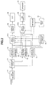
- FIGURE 2 shows an example of configuration of the digital TV 1.
- the 1394 receiver 11 receives data (packets) transmitted via the AV bus 6 according to a format of an IEEE 1394 standard and outputs the received data to a separating circuit 12 (supplying unit).
- the separating circuit 12 determines the format of this data by referring to a prescribed region (to be described later) of a CIP (Common Isochronous Packet) header of the received data and then outputs this data to the decoder corresponding to this format.
- CIP Common Isochronous Packet
- the separating circuit 12 outputs this data to an MPEG-PS decoder 13 (the first decoder) when the supplied data is MPEG-PS data.
- the separating circuit 12 outputs this data to an MPEG-TS decoder 14 (the second decoder).
- the supplied data is DVCR SD data
- this data is outputted to a DVCR SD decoder 15 (the third decoder).
- the MPEG-TS decoder 14 decodes supplied MPEG-TS data, outputs a generated digital video signal to a synthesis circuit 16 and a multiplexer 17-1, and outputs a generated digital audio signal to a multiplexer 17-2.
- the MPEG-TS decoder 14 has a built-in memory 51 having a storage capacity of at least 1.2 megabytes. This memory 51 is used as a video transport buffer and a decoder buffer conforming to MPEG standards.
- the video transport buffer is a buffer of a total of 234.5 kilobytes, with a 0.5 kilobyte transport buffer (TB: Transport Buffer), 10 kilobyte main buffer (MB: Main Buffer) and a 224 kilobyte elementary stream buffer (EB: Elementary Stream Buffer).
- Transport Buffer Transport Buffer
- MB Main Buffer
- EB Elementary Stream Buffer
- the transport buffer of these buffers is used when a header of a packet for the MPEG-TS data is removed.
- the main buffer is provided to slow down the rate of the data transfer to the elementary stream buffer.
- the rate of transfer from the transport buffer to the main buffer is set to be the rate at the time of multiplexing (for example, 18 Mbps) but the rate of the data transfer from the main buffer to the elementary stream buffer is set to be a lower rate (for example, 15 Mbps).
- the elementary stream buffer stores the contents of the elementary stream until the arrival of the time corresponding to time stamps PTS (Presentation Time Stamp) and DTS (Decoding Time Stamp) included in the MPEG data.
- PTS Presentation Time Stamp
- DTS Decoding Time Stamp
- data for one access unit is outputted to a built-in decoder (not shown in the drawings) in the MPEG-TS decoder 14. Data outputted from the elementary stream buffer is then decoded by this decoder.
- the decoder buffer When carrying out decoding using the MPEG format, the decoder buffer holds the image (picture) to be decoded and a picture for comparing (I picture, P picture etc.). A storage capacity for at least two pictures (an I picture and a P picture) is therefore required at the decoder buffer.
- one picture comprises 720 x 480 pixels.
- one picture comprises 720 x 576 pixels and the ratio of the luminance signal Y and the two color difference signals Cb and Cr is 4:2:0.
- a storage capacity of at least 1.2 megabytes ( ⁇ 1.0 Megabytes + 234.5 megabytes) is therefore required for the memory 51.
- the MPEG-PS decoder 13 decodes supplied MPEG-PS data, outputs a generated digital video signal to the synthesis circuit 16 and the multiplexer 17-1, and outputs generated digital audio data to the multiplexer 17-2.
- the MPEG-PS decoder 13 has a built-in memory 41 having a storage capacity of at least 1.2 Megabytes. This memory 41 is used as the aforementioned main buffer, the elementary stream buffer and the decoder buffer. A storage capacity of 8 kilobytes is sufficient for the main buffer in the MPEG-PS decoder 13.
- the DVCR-SD decoder 15 decodes supplied DVCR SD data, outputs a generated digital video signal to the synthesis circuit 16 and the multiplexer 17-1, and outputs generated digital audio data to the multiplexer 17-2.
- the synthesis circuit 16 performs synthesis for digital signals supplied by the MPEG-PS decoder 13, MPEG-TS decoder 14 and DVCR-SD decoder 15 in such a manner that, for example, three images are displayed in a single picture, with the synthesized digital video signal then being outputted to the multiplexer 17-1.
- the circuit disclosed in, for example, U.S. Pat. No. 4,746,983 can be utilized as the synthesis circuit 16.
- the circuit disclosed in, for example, Unexamined Published Japanese Patent Application No. 56-136089 can be utilized as the synthesis circuit 16.
- the circuit disclosed in Unexamined Published Japanese Patent Application No. 61-194982 can be utilized as the synthesis circuit 16.
- the multiplexer 17-1 outputs any one of the digital signals supplied from the MPEG-PS decoder 13, MPEG-TS decoder 14, DVCR-SD decoder 15 and synthesis circuit 16 to a display circuit 18 in response to a control signal supplied from a control circuit 22.
- the multiplexer 17-2 outputs any one of the digital audio signals supplied from the MPEG-PS decoder 13, MPEG-TS decoder 14 and DVCR-SD decoder 15 to a D/A converter 20 in response to a control signal supplied by the control circuit 22.
- the display circuit 18 displays an image corresponding to a supplied digital video signal on a CRT 19.
- the D/A converter 20 converts the supplied digital audio signal to an analog audio signal and outputs sound corresponding to this signal at a speaker 21.
- the control circuit 22 receives signals corresponding to user operations from an input unit 23 and outputs prescribed control signals corresponding to these signals to the multiplexer 17-1, the multiplexer 17-2 and the synthesis circuit 16.
- the 1394 receiver 11 of the digital TV 1 receives packets transmitted with asynchronous communications and data (data fields) included in the received packets is outputted to the separating circuit 12.
- FIGURE 3 shows the configuration of packets for asynchronous communication.
- Asynchronous communications packets comprise a packet header, a header CRC, a data field and a data CRC.
- the packet header further comprises "Data_length” expressing the length of the data, "Tag” expressing the kinds of data format transmitted by this packet, "Channel” expressing the channel number of this packet (one of 0 to 63), "tcode” expressing the processing code and synchronization code “Sy” specified in each application.
- Header CRC (Header_CRC) is packet header error detection code and data CRC (Data_CRC) is data field (Data field) error detection code.
- a data field comprises a CIP header and real time data of which the real time data is the original data that is transmitted.
- FIGURE 4 shows a CIP header format.
- the CIP header comprises a send node number SID, a packeting unit DBS, a dividing number FN for data in packeting, a quadlet number QPC (one quadlet is four bytes) added to fit data lengths to a prescribed fixed data length at the time of dividing, a source packet header flag SPH, a counter DBC for detecting missing of packets, a signal format FMT and a format dependent field FDF.
- rsv is a reserved region.
- the separating circuit 12 refers to the value of the FMT region of the CIP header of the supplied data and determines which of MPEG-PS data, MPEG-TS data and DVCR SD data the supplied data is in accordance with this value.
- the separating circuit 12 determines that the data is MPEG-PS data, this data is outputted to the MPEG-PS decoder 13.
- the data is determined to be MPEG-TS data
- this data is outputted to the MPEG-TS decoder 14.
- the data is determined to be DVCR-SD data, this data is outputted to the DVCR-SD decoder 15.
- this data is then decoded by one of the MPEG-PS decoder 13, MPEG-TS decoder 14 or the DVCR-SD decoder 15, with a generated digital video signal then being outputted to the synthesis circuit 16 and the multiplexer 17-1 and a generated digital audio signal being outputted to the multiplexer 17-2.
- the synthesis circuit 16 then synthesizes the digital video signals with a pattern designated by the control circuit 22 so that images corresponding to digital video signals supplied by the MPEG-PS decoder 13, MPEG-TS decoder 14 and DVCR-SD decoder 15 are displayed on one picture, with the synthesized digital video signal then being outputted to the multiplexer 17-1.
- FIGURE 5 shows an example of displaying a synthesized image.
- the image corresponding to the SD data of the DVCR is displayed at a region to the upper left of the picture as the image from the DVCR 4
- the image corresponding to the MPEG-TS data is displayed at a region to the upper right of the picture as the image from the STB 5
- the image corresponding to the MPEG-PS data is displayed at a region to the lower left of the picture as the image from the DVD player 2.
- the name of the device supplying each image (“DVCR”, "STB” and “DVD player” of FIG. 5) is displayed at the lower side of each region at which each image is displayed.
- data of differing formats is received in asynchronous communications in parallel by the 1394 receiver 11.
- a plurality of images respectively corresponding to these data can therefore be displayed simultaneously on one picture in real time.
- the multiplexer 17-1 outputs digital video signals designated by the control circuit 22 (i.e. selected as a result of user operations of the input part 23) to the display circuit 18.
- the display circuit 18 displays images corresponding to the supplied video signals on the CRT 19.
- the multiplexer 17-2 outputs digital audio signals designated by the control circuit 22 to the D/A converter 20.
- the D/A converter 20 then converts these digital audio signals into analog audio signals, with sound corresponding to these analog audio signals being outputted at the speaker 21.
- the digital TV 1 receives data of each format via the AV bus 6, decodes this data using a decoder corresponding to the format of this data and plays back images and sound.
- data of the first to third formats is received via a digital interface conforming to IEEE 1394 standards and the received data is supplied to any of the first to third decoders in accordance with the formats of the data.
- the data can then be decoded at any of the first to third decoders. It is therefore possible to play back a plurality of kinds of image data using a single device and the scale of the device can therefore be reduced.
Abstract
In order to play back a plurality of kinds of image
data using a single device, a 1394 receiver (11) receives
data transmitted via an AV bus according to a format of an
IEEE 1394 standard. A separating circuit (12) then
determines the format of this data by referring to a
prescribed region of a CIP header of this data. When this
data is MPEG-PS data, it is outputted to an MPEG-PS decoder
(13). When this data is MPEG-TS data, it is outputted to
an MPEG-TS decoder (14). When this data is DVCR SD data,
it is outputted to a DVCR-SD decoder (15). The MPEG-PS
decoder (13), MPEG-TS decoder (14) and the DVCR-SD decoder
(15) then decode the supplied data of the respective
formats.
Description
The present invention relates to receiving devices and
methods for decoding received data at any of a plurality of
decoders in accordance with a format of the received data.
In recent years, DVD (Digital Versatile Disc) -Video
has been standardized, so
that it is expected to become widespread. With the DVDs,
video data is compressed using an MPEG (Moving Picture
Experts Group) - PS (Program Stream) method and recorded. A
DVD player plays back a DVD at a driving unit, with MPEG-PS
data played back from the DVD being decoded at a decoder and
outputted to a television. An image corresponding to this
data is then displayed.
On the other hand, digital satellite broadcasts are
also becoming widespread. Video data transmitted by these
digital satellite broadcasts is compressed using an MPEG-TS
(Transport Stream). A receiver for receiving the digital
satellite broadcasts then has a built-in decoder for
decoding MPEG-TS data.
However, as described above, when a number of images
such as digital satellite broadcast images or images from
digital video cassette recorders (DVCR) etc. are to be
enjoyed in addition to the images played back by the DVD
player, because of the image data formats being different
in correspondence to these images, mutually independent
playback systems have to be provided in order to play back
all of the image data. This therefore causes the device to
be large in size.
According to one aspect of the present invention, a
receiving device for receiving data encoded in a prescribed
data format from a plurality of transmitting devices via a
digital interface, and decoding the data in accordance with
the prescribed data format, comprises a receiver, a first
decoder, a second decoder and a supplying unit. The
receiver is for receiving at least data of the first and
second formats. The first decoder is for decoding the data
of the first format. The second decoder is for decoding
the data of the second format. The supplying unit is for
supplying data received by the
receiver to either of the first and second decoders in
accordance with a format of the data.
In this receiving device, the data can be included
within a packet and the supplying unit supplies data
received by the receiver to either of the first and second
decoders in accordance with a value corresponding to a
format of the data written to a prescribed region of the
packet.
The prescribed region can be a common isochronous
packet (CIP) header of an isochronous packet.
The digital interface can be a digital interface
conforming to an Institute of Electrical and Electronics
Engineers (IEEE) 1394 standard.
The receiver can receive packets having data of
whichever of the first and second formats transmitted in
isochronous communications of the Institute of Electrical
and Electronics Engineers 1394 standard.
The receiving device can further comprise a multiplexer
to which data outputted from the first and second decoders
are inputted and a display circuit for displaying output
data from the multiplexer. The receiver receives the data
of the first and second formats in parallel in the
isochronous communications and the display circuit displays
a plurality of images corresponding to each of the data
simultaneously in a single picture in real time.
The receiver of this receiving device can also be made
to be capable of receiving data of the third format, and
further comprise the third decoder for decoding the data of
the third format.
Further, the first, second and third formats can be a
program stream format, of Moving Picture Experts Group
(MPEG) system, a transport stream format of MPEG system and
a standard definition (SD) format of digital video cassette
recorder, respectively.
Moreover, the first and second decoders can each
comprise a storage means having a storage capacity of at
least 1.2 megabytes for temporarily storing data when
decoding.
According to another aspect of the present invention,
a receiving method for receiving data encoded in a
prescribed data format from a plurality of transmitting
devices via a digital interface and decoding the data in
accordance with the prescribed data format, comprises the
steps of receiving at least data of first and second
formats, supplying the received data to either of first and
second decoders in accordance with a format of the data,
and decoding the received data at either of the first and
second decoders.
In this receiving method, the data can be included
within a packet and the received data is then supplied to
either of the first and second decoders in accordance with
a value corresponding to a format of the data written to a
prescribed region of the packet.
The prescribed region can be a common isochronous
packet (CIP) header of an isochronous packet.
The digital interface can be a digital interface
conforming to an Institute of Electrical and Electronics
Engineers 1394 standard.
The received packets can be packets having data of
whichever of the first and second formats transmitted in
isochronous communications of the Institute of Electrical
and Electronics Engineers 1394 standard.
Further, with this receiving method, each of data
outputted from the first and second decoders can be
multiplexed and the multiplexed output data can be
displayed, the data of the first and second formats can be
received in parallel in the isochronous communications, and
a plurality of images each corresponding to each of the
data can be displayed simultaneously in a single picture in
real time.
Thus a preferred embodiment of the present invention
enables playback of data of different data format images
using a single device by connecting a plurality of devices
handling these various kinds of image data via a digital
interface to a device having a plurality of decoders for
decoding the image data.
The invention will now be described by way of example
with reference to the accompanying drawings, throughout
which like parts are referred to by like references, and in
which:
FIGURE 1 shows an example of a configuration of an AV
system. In this AV system, a digital television (digital
TV) 1 to which the receiving device embodying the present
invention is applied is connected to an AV bus 6. A built-in
1394 receiver 11 then receives MPEG-PS data,
MPEG-TS data and DVCR SD (Standard Definition) data supplied
via the AV bus 6. This data is decoded at built-in decoders
so that a decoded image is displayed.
A DVD player 2 reads out MPEG-PS data recorded on a DVD
and outputs this data to the digital TV 1 via the AV bus 6
with the data being un-decoded.
A personal computer 3 carries out various processings
using software and carries out playback of DVD ROMs etc., in
addition to DVD-Video using a built-in DVD drive 21 so that
image data such as MPEG-PS data, MPEG-TS data and SD data
for DVCR etc., are outputted to the digital TV 1 via the AV
bus 6.
A DVCR 4 records or plays back image data to or from
video cassette tape and outputs DVCR SD data read out from
the video cassette tape to the digital TV 1 via the AV bus
6.
A Set-Top Box (STB) 5 receives broadcast signals
transmitted from man-made satellites for predetermined
digital satellite broadcasts via an antenna 41 and outputs
image data (MPEG-TS data) for, for example, programs
selected by a user, to the digital TV 1 via the AV bus 6.
The AV bus 6 is a bus which conforms to the IEEE (The
Institute of Electrical and Electronics Engineers) 1394,
High Performance Serial Bus Standard (IEEE 1394 standard).
FIGURE 2 shows an example of configuration of the
digital TV 1.
At the digital TV 1, the 1394 receiver 11 receives data
(packets) transmitted via the AV bus 6 according to a format
of an IEEE 1394 standard and outputs the received data to a
separating circuit 12 (supplying unit).
The separating circuit 12 determines the format of this
data by referring to a prescribed region (to be described
later) of a CIP (Common Isochronous Packet) header of the
received data and then outputs this data to the decoder
corresponding to this format.
Namely, the separating circuit 12 outputs this data to
an MPEG-PS decoder 13 (the first decoder) when the supplied
data is MPEG-PS data. When the supplied data is MPEG-TS
data, the separating circuit 12 outputs this data to an
MPEG-TS decoder 14 (the second decoder). When the supplied
data is DVCR SD data, this data is outputted to a DVCR SD
decoder 15 (the third decoder).
The MPEG-TS decoder 14 decodes supplied MPEG-TS data,
outputs a generated digital video signal to a synthesis
circuit 16 and a multiplexer 17-1, and outputs a generated
digital audio signal to a multiplexer 17-2.
The MPEG-TS decoder 14 has a built-in memory 51 having
a storage capacity of at least 1.2 megabytes. This memory
51 is used as a video transport buffer and a decoder buffer
conforming to MPEG standards.
The video transport buffer is a buffer of a total of
234.5 kilobytes, with a 0.5 kilobyte transport buffer (TB:
Transport Buffer), 10 kilobyte main buffer (MB: Main Buffer)
and a 224 kilobyte elementary stream buffer (EB: Elementary
Stream Buffer).
The transport buffer of these buffers is used when a
header of a packet for the MPEG-TS data is removed.
The main buffer is provided to slow down the rate of
the data transfer to the elementary stream buffer. The rate
of transfer from the transport buffer to the main buffer is
set to be the rate at the time of multiplexing (for example,
18 Mbps) but the rate of the data transfer from the main
buffer to the elementary stream buffer is set to be a lower
rate (for example, 15 Mbps).
The elementary stream buffer stores the contents of the
elementary stream until the arrival of the time
corresponding to time stamps PTS (Presentation Time Stamp)
and DTS (Decoding Time Stamp) included in the MPEG data. At
the arrival of the time, data for one access unit is
outputted to a built-in decoder (not shown in the drawings)
in the MPEG-TS decoder 14. Data outputted from the
elementary stream buffer is then decoded by this decoder.
When carrying out decoding using the MPEG format, the
decoder buffer holds the image (picture) to be decoded and a
picture for comparing (I picture, P picture etc.). A
storage capacity for at least two pictures (an I picture and
a P picture) is therefore required at the decoder buffer.
When the image signal is of the NTSC format, one
picture comprises 720 x 480 pixels. As the ratio of a
luminance signal Y and two color difference signals Cb and
Cr is then 4:2:0, the storage capacity required per one
picture is approximately 0.5 Megabytes (=720 x 480 x
(4+2+0)/4). Therefore, in this case, a storage capacity of
approximately 1.0 Megabytes is required for the decoder
buffer for two pictures.
On the other hand, when the image signal is in the PAL
format, one picture comprises 720 x 576 pixels and the ratio
of the luminance signal Y and the two color difference
signals Cb and Cr is 4:2:0. The storage capacity required
per one picture is therefore approximately 0.6 Megabytes
(=720 x 576 x (4+2+0)/4). Therefore, in this case, a
storage capacity of approximately 1.2 Megabytes is required
for the decoder buffer for two pictures.
A storage capacity of at least 1.2 megabytes (≒ 1.0
Megabytes + 234.5 megabytes) is therefore required for the
memory 51.
The MPEG-PS decoder 13 decodes supplied MPEG-PS data,
outputs a generated digital video signal to the synthesis
circuit 16 and the multiplexer 17-1, and outputs generated
digital audio data to the multiplexer 17-2.
The MPEG-PS decoder 13 has a built-in memory 41 having
a storage capacity of at least 1.2 Megabytes. This memory
41 is used as the aforementioned main buffer, the elementary
stream buffer and the decoder buffer. A storage capacity of
8 kilobytes is sufficient for the main buffer in the MPEG-PS
decoder 13.
The DVCR-SD decoder 15 decodes supplied DVCR SD data,
outputs a generated digital video signal to the synthesis
circuit 16 and the multiplexer 17-1, and outputs generated
digital audio data to the multiplexer 17-2.
The synthesis circuit 16 performs synthesis for digital
signals supplied by the MPEG-PS decoder 13, MPEG-TS decoder
14 and DVCR-SD decoder 15 in such a manner that, for
example, three images are displayed in a single picture,
with the synthesized digital video signal then being
outputted to the multiplexer 17-1.
For example, when one image of the three images is
taken to be a main image and another image is taken to be a
sub-image for generating an image where the sub-image is set
into the main image, the circuit disclosed in, for example,
U.S. Pat. No. 4,746,983 can be utilized as the synthesis
circuit 16.
When three images are then arranged so as to be
displayed as one picture, the circuit disclosed in, for
example, Unexamined Published Japanese Patent Application
No. 56-136089 can be utilized as the synthesis circuit 16.
In addition, when synthesizing a character string such
as the name of the device that outputted the image data, the
circuit disclosed in Unexamined Published Japanese Patent
Application No. 61-194982 can be utilized as the synthesis
circuit 16.
The multiplexer 17-1 outputs any one of the digital
signals supplied from the MPEG-PS decoder 13, MPEG-TS
decoder 14, DVCR-SD decoder 15 and synthesis circuit 16 to a
display circuit 18 in response to a control signal supplied
from a control circuit 22.
The multiplexer 17-2 outputs any one of the digital
audio signals supplied from the MPEG-PS decoder 13, MPEG-TS
decoder 14 and DVCR-SD decoder 15 to a D/A converter 20 in
response to a control signal supplied by the control circuit
22.
The display circuit 18 displays an image corresponding
to a supplied digital video signal on a CRT 19.
The D/A converter 20 converts the supplied digital
audio signal to an analog audio signal and outputs sound
corresponding to this signal at a speaker 21.
The control circuit 22 receives signals corresponding
to user operations from an input unit 23 and outputs
prescribed control signals corresponding to these signals to
the multiplexer 17-1, the multiplexer 17-2 and the synthesis
circuit 16.
Next, the operation of the digital TV 1 will be
described.
First, the 1394 receiver 11 of the digital TV 1
receives packets transmitted with asynchronous
communications and data (data fields) included in the
received packets is outputted to the separating circuit 12.
FIGURE 3 shows the configuration of packets for
asynchronous communication. Asynchronous communications
packets comprise a packet header, a header CRC, a data field
and a data CRC.
The packet header further comprises "Data_length"
expressing the length of the data, "Tag" expressing the
kinds of data format transmitted by this packet, "Channel"
expressing the channel number of this packet (one of 0 to
63), "tcode" expressing the processing code and
synchronization code "Sy" specified in each application.
Header CRC (Header_CRC) is packet header error detection
code and data CRC (Data_CRC) is data field (Data field)
error detection code. A data field comprises a CIP header
and real time data of which the real time data is the
original data that is transmitted.
FIGURE 4 shows a CIP header format. The CIP header
comprises a send node number SID, a packeting unit DBS, a
dividing number FN for data in packeting, a quadlet number
QPC (one quadlet is four bytes) added to fit data lengths to
a prescribed fixed data length at the time of dividing, a
source packet header flag SPH, a counter DBC for detecting
missing of packets, a signal format FMT and a format
dependent field FDF. Here, rsv is a reserved region.
Next, the separating circuit 12 refers to the value of
the FMT region of the CIP header of the supplied data and
determines which of MPEG-PS data, MPEG-TS data and DVCR SD
data the supplied data is in accordance with this value.
When the separating circuit 12 determines that the data
is MPEG-PS data, this data is outputted to the MPEG-PS
decoder 13. When the data is determined to be MPEG-TS data,
this data is outputted to the MPEG-TS decoder 14. When the
data is determined to be DVCR-SD data, this data is
outputted to the DVCR-SD decoder 15.
When this data is supplied, this data is then decoded
by one of the MPEG-PS decoder 13, MPEG-TS decoder 14 or the
DVCR-SD decoder 15, with a generated digital video signal
then being outputted to the synthesis circuit 16 and the
multiplexer 17-1 and a generated digital audio signal being
outputted to the multiplexer 17-2.
The synthesis circuit 16 then synthesizes the digital
video signals with a pattern designated by the control
circuit 22 so that images corresponding to digital video
signals supplied by the MPEG-PS decoder 13, MPEG-TS decoder
14 and DVCR-SD decoder 15 are displayed on one picture, with
the synthesized digital video signal then being outputted to
the multiplexer 17-1.
FIGURE 5 shows an example of displaying a synthesized
image. In the example of the display of FIG. 5, the image
corresponding to the SD data of the DVCR is displayed at a
region to the upper left of the picture as the image from
the DVCR 4, the image corresponding to the MPEG-TS data is
displayed at a region to the upper right of the picture as
the image from the STB 5 and the image corresponding to the
MPEG-PS data is displayed at a region to the lower left of
the picture as the image from the DVD player 2.
The name of the device supplying each image ("DVCR",
"STB" and "DVD player" of FIG. 5) is displayed at the lower
side of each region at which each image is displayed.
In this embodiment data of differing formats is
received in asynchronous communications in parallel by the
1394 receiver 11. A plurality of images respectively
corresponding to these data can therefore be displayed
simultaneously on one picture in real time.
Next, of the supplied digital video signals, the
multiplexer 17-1 outputs digital video signals designated by
the control circuit 22 (i.e. selected as a result of user
operations of the input part 23) to the display circuit 18.
The display circuit 18 then displays images corresponding to
the supplied video signals on the CRT 19.
On the other hand, of the supplied digital audio
signals, the multiplexer 17-2 outputs digital audio signals
designated by the control circuit 22 to the D/A converter
20. The D/A converter 20 then converts these digital audio
signals into analog audio signals, with sound corresponding
to these analog audio signals being outputted at the speaker
21.
In the above way, the digital TV 1 receives data of
each format via the AV bus 6, decodes this data using a
decoder corresponding to the format of this data and plays
back images and sound.
In the AV system of FIG. 1, only one digital TV 1 is
connected to the AV bus 6, but other digital TVs 1 can be
connected to the AV bus 6, with data of a plurality of
formats then being decoded in the same manner.
As described above, data of the first
to third formats is received via a digital interface
conforming to IEEE 1394 standards and the received data is
supplied to any of the first to third decoders in accordance
with the formats of the data. The data can then be decoded
at any of the first to third decoders. It is therefore
possible to play back a plurality of kinds of image data
using a single device and the scale of the device can
therefore be reduced.
Claims (18)
- A receiving device for receiving data encoded in a prescribed data format from a plurality of transmitting devices via a digital interface and decoding said data in accordance with said prescribed data format, comprising:a receiver for receiving at least data of first and second formats;a first decoder for decoding said data of first format;a second decoder for decoding said data of second format; anda supplying unit for supplying data received by said receiver to either of said first and second decoders in accordance with a format of said data.
- The receiving device of claim 1, wherein said data is included within a packet and said supplying unit supplies data received by said receiver to either of said first and second decoders in accordance with a value corresponding to a format of said data written to a prescribed region of said packet.
- The receiving device of claim 2, wherein said prescribed region is a common isochronous packet header of an isochronous packet.
- The receiving device of claim 1, wherein said digital interface is a digital interface conforming to an Institute of Electrical and Electronics Engineers 1394 standard.
- The receiving device of claim 1, wherein said receiver receives packets having data of whichever of said first and second formats transmitted in isochronous communications of said Institute of Electrical and Electronics Engineers 1394 standard.
- The receiving device of claim 5 further comprising:a multiplexer to which data outputted from said first and second decoders are inputted; anda display circuit for displaying output data from said multiplexer,said receiver receiving said data of first and second formats in parallel in said isochronous communications, andsaid display circuit displaying a plurality of images corresponding to each of said data simultaneously in a single picture in real time.
- The receiving device of claim 1, wherein said receiver is made to be capable of receiving data of third format, and further comprises a third decoder for decoding said data of third format.
- The receiving device of claim 1, wherein said first format is a program stream format of Moving Picture Experts Group system.
- The receiving device of claim 1, wherein said second format is a transport stream format of Moving Picture Experts Group system.
- The receiving device of claim 7, wherein said third format is a standard definition format of digital video cassette recorder.
- The receiving device of claim 8, wherein said first decoder comprises a storage for temporarily storing data when decoding, said storage having a storage capacity of at least 1.2 megabytes.
- The receiving device of claim 9, wherein said second decoder comprises a storage for temporarily storing data when decoding, said storage having a storage capacity of at least 1.2 megabytes.
- A receiving method for receiving data encoded in a prescribed data format from a plurality of transmitting devices via a digital interface and decoding said data in accordance with said prescribed data format, comprising the steps of:receiving at least data of first and second formats;supplying received data to either of first and second decoders in accordance with a format of said data; anddecoding said data at either of said first and second decoders.
- The receiving method of claim 13, wherein said data is included within a packet and said received data is supplied to either of said first and second decoders in accordance with a value corresponding to a format of said data written to a prescribed region of said packet.
- The receiving method of claim 14, wherein said prescribed region is a common isochronous packet header of an isochronous packet.
- The receiving method of claim 13, wherein said digital interface is a digital interface conforming to an Institute of Electrical and Electronics Engineers 1394 standard.
- The receiving method of claim 13, wherein packets having data of whichever of said first and second formats are received, said data being transmitted in isochronous communications of said Institute of Electrical and Electronics Engineers 1394 standard.
- The receiving method of claim 17, wherein each of data outputted from said first and second decoders is multiplexed and multiplexed output data is displayed,said data of first and second formats are received in parallel in said isochronous communications, anda plurality of images each corresponding to each of said data are displayed simultaneously in a single picture in real time.
Applications Claiming Priority (2)
| Application Number | Priority Date | Filing Date | Title |
|---|---|---|---|
| JP8304401A JPH10145753A (en) | 1996-11-15 | 1996-11-15 | Receiver and its method |
| JP304401/96 | 1996-11-15 |
Publications (1)
| Publication Number | Publication Date |
|---|---|
| EP0843482A2 true EP0843482A2 (en) | 1998-05-20 |
Family
ID=17932575
Family Applications (1)
| Application Number | Title | Priority Date | Filing Date |
|---|---|---|---|
| EP97309079A Withdrawn EP0843482A2 (en) | 1996-11-15 | 1997-11-12 | Receiving devices and methods |
Country Status (4)
| Country | Link |
|---|---|
| US (1) | US5973748A (en) |
| EP (1) | EP0843482A2 (en) |
| JP (1) | JPH10145753A (en) |
| KR (1) | KR19980042407A (en) |
Cited By (26)
| Publication number | Priority date | Publication date | Assignee | Title |
|---|---|---|---|---|
| EP0981249A2 (en) * | 1998-08-17 | 2000-02-23 | Sharp Kabushiki Kaisha | Buffer system for controlled and synchronised presentation of MPEG-2 data services |
| GB2341298A (en) * | 1998-06-19 | 2000-03-08 | Samsung Electronics Co Ltd | Remote control of a DVD player via a display device |
| EP1018840A2 (en) * | 1998-12-08 | 2000-07-12 | Canon Kabushiki Kaisha | Digital receiving apparatus and method |
| US6101215A (en) * | 1997-02-12 | 2000-08-08 | Matsushita Electric Industrial Co., Ltd. | Data transmission apparatus, data reception apparatus, and medium |
| WO2000060478A2 (en) * | 1999-04-01 | 2000-10-12 | Thomson Licensing S.A. | Method for the compilation of bus packets for isochronous data transmission via a data bus, and apparatus for carrying out the method |
| WO2001002183A1 (en) * | 1999-07-05 | 2001-01-11 | Sony Corporation | Data printing system, data printing method and recording medium |
| EP1081948A2 (en) * | 1999-08-31 | 2001-03-07 | Matsushita Electric Industrial Co., Ltd. | Audio video information apparatus equipped with digital interface |
| EP1085759A2 (en) * | 1999-09-14 | 2001-03-21 | Sony Corporation | Electronic devices and methods for data processing |
| US6378000B1 (en) | 1999-04-29 | 2002-04-23 | Mitsubish Electric Research Laboratories, Inc | Address mapping in home entertainment network |
| US6496862B1 (en) | 1998-08-25 | 2002-12-17 | Mitsubishi Electric Research Laboratories, Inc. | Remote monitoring and control of devices connected to an IEEE 1394 bus via a gateway device |
| US6505255B1 (en) | 1999-04-29 | 2003-01-07 | Mitsubishi Electric Information Technology Center America, Inc. (Ita) | Method for formatting and routing data between an external network and an internal network |
| DE10136176A1 (en) * | 2001-07-25 | 2003-02-13 | Thomson Brandt Gmbh | Digital video device for integration in the network |
| US6523064B1 (en) | 1999-04-29 | 2003-02-18 | Mitsubishi Electric Research Laboratories, Inc | Network gateway for collecting geographic data information |
| WO2003047261A1 (en) * | 2001-11-30 | 2003-06-05 | Matsushita Electric Industrial Co., Ltd. | A method and an apparatus for stream conversion, a method and an apparatus for data recording, and data recording medium |
| US6633547B1 (en) | 1999-04-29 | 2003-10-14 | Mitsubishi Electric Research Laboratories, Inc. | Command and control transfer |
| DE19964394B4 (en) * | 1998-06-19 | 2004-09-16 | Samsung Electronics Co., Ltd., Suwon | Transmission device for transferring digital video disc information over a network |
| DE19927711B4 (en) * | 1998-06-19 | 2004-09-23 | Samsung Electronics Co., Ltd., Suwon | Device for transmitting information over a network |
| US6892242B1 (en) | 1999-09-21 | 2005-05-10 | Sony Corporation | Information processing apparatus and method, and recording medium used therewith |
| EP1499135A3 (en) * | 2003-07-18 | 2006-04-12 | Canon Kabushiki Kaisha | Digital data multiplexing and demultiplexing |
| US7032059B1 (en) * | 1998-02-12 | 2006-04-18 | Matsushita Electric Industrial Co., Ltd. | Method of data transmission management |
| EP1648140A1 (en) * | 1999-09-14 | 2006-04-19 | Sony Corporation | Communication system and method in audio and music data transmission |
| EP1655964A3 (en) * | 1998-05-06 | 2007-09-05 | Samsung Electronics Co., Ltd. | Method for displaying devices in network |
| US7274861B2 (en) | 2003-04-10 | 2007-09-25 | Matsushita Electric Industrial Co., Ltd. | Information recording medium, and apparatus and method for recording information to information recording medium |
| EP1843575A1 (en) * | 2006-04-03 | 2007-10-10 | C.I.D.P. | Electronic device for receiving and displaying data coming from a multimedia PC and/or from another receiver/decoder |
| US7386223B2 (en) | 2001-11-30 | 2008-06-10 | Matsushita Electric Industrial Co., Ltd. | Method and an apparatus for stream conversion a method and an apparatus for data recording and data recording medium |
| US7945143B2 (en) | 2001-07-23 | 2011-05-17 | Panasonic Corporation | Information recording medium, and apparatus and method for recording information on information recording medium |
Families Citing this family (51)
| Publication number | Priority date | Publication date | Assignee | Title |
|---|---|---|---|---|
| US7221853B1 (en) | 1996-09-05 | 2007-05-22 | Sony Corporation | Digital recording apparatus and copyright protection method thereof |
| JP3941178B2 (en) | 1996-09-05 | 2007-07-04 | ソニー株式会社 | Recording medium, digital recording device, and control IC |
| MY121267A (en) | 1996-09-05 | 2006-01-28 | Sony Corp | Digital recording apparatus and copyright protection method thereof |
| US6763037B1 (en) * | 1996-10-22 | 2004-07-13 | Sony Corporation | Transmitting apparatus and method, receiving apparatus and method |
| KR100261706B1 (en) | 1996-12-17 | 2000-07-15 | 가나이 쓰도무 | Digital broadcasting signal receiving device and, receiving and recording/reproducing apparatus |
| JP3870983B2 (en) | 1997-02-17 | 2007-01-24 | ソニー株式会社 | Electronic device control apparatus and method, and electronic device |
| JP4367971B2 (en) | 1997-06-05 | 2009-11-18 | ソニー株式会社 | Electronic device control apparatus, electronic device control method, and electronic device |
| KR100309099B1 (en) * | 1997-06-21 | 2001-12-15 | 윤종용 | Method and apparatus for selecting channel |
| US6131129A (en) * | 1997-07-30 | 2000-10-10 | Sony Corporation Of Japan | Computer system within an AV/C based media changer subunit providing a standarized command set |
| JP3564961B2 (en) | 1997-08-21 | 2004-09-15 | 株式会社日立製作所 | Digital broadcast receiver |
| KR100249228B1 (en) * | 1997-08-28 | 2000-03-15 | 구자홍 | Aspect Ratio Conversion Apparatus in Digital Television |
| TW392402B (en) | 1997-10-22 | 2000-06-01 | Hitachi Ltd | Method for using audio and video machine and audio and video machine system |
| US6678006B1 (en) * | 1998-01-07 | 2004-01-13 | Ati Technologies, Inc. | Method and apparatus for video processing that includes sub-picture scaling |
| US6373821B2 (en) * | 1998-02-20 | 2002-04-16 | Apple Computer, Inc. | Method for setting time stamp in SYT field of packet headers for IEEE-1394 devices |
| KR100511250B1 (en) * | 1998-04-09 | 2005-11-03 | 엘지전자 주식회사 | Digital Audio / Video (A / V) Systems |
| US6202210B1 (en) * | 1998-08-21 | 2001-03-13 | Sony Corporation Of Japan | Method and system for collecting data over a 1394 network to support analysis of consumer behavior, marketing and customer support |
| JP2000261482A (en) | 1999-03-08 | 2000-09-22 | Sony Corp | Address setting method, client device, server and client server system |
| US6751228B1 (en) | 1999-03-23 | 2004-06-15 | Yamaha Corporation | Packet handler of audio data by isochronous mode |
| US6757025B1 (en) * | 1999-04-09 | 2004-06-29 | Sony Corporation | Method for switching input terminals based on incoming signal format |
| US6826776B1 (en) | 1999-04-09 | 2004-11-30 | Sony Corporation | Method and apparatus for determining signal path |
| US6731347B1 (en) | 1999-04-09 | 2004-05-04 | Sony Corporation | Method for switching signal input based on device capability |
| AU4208600A (en) * | 1999-04-09 | 2000-11-14 | Sony Electronics Inc. | Method for switching signal input based on device capability |
| US6976267B1 (en) | 1999-04-09 | 2005-12-13 | Sony Corporation | Method and apparatus for controlling connections between devices |
| JP4147689B2 (en) * | 1999-06-14 | 2008-09-10 | ソニー株式会社 | Information processing apparatus and information processing method |
| US6341375B1 (en) | 1999-07-14 | 2002-01-22 | Lsi Logic Corporation | Video on demand DVD system |
| JP2001066986A (en) | 1999-08-26 | 2001-03-16 | Sony Corp | Transmitter and method, receiver and method, communication system, and program storage medium |
| JP2001077831A (en) | 1999-09-08 | 2001-03-23 | Sony Corp | Communication controller, method, communication system and program storage medium |
| JP4168304B2 (en) * | 1999-09-16 | 2008-10-22 | ソニー株式会社 | Information output device, information notification method, and information signal supply route selection method |
| KR100635000B1 (en) * | 1999-11-08 | 2006-10-16 | 삼성전자주식회사 | multi-screen digital TV receiver using the interface module which can differentiate the specific source streams |
| JP2001237860A (en) * | 2000-02-21 | 2001-08-31 | Sony Corp | Communication control method and communication controller |
| FR2811846B1 (en) * | 2000-07-17 | 2002-09-27 | Thomson Multimedia Sa | METHOD AND DEVICE FOR READING RECORDED MPEG DATA TRANSMITTED ON AN IEEE 1394 BUS |
| US6741292B1 (en) * | 2000-11-06 | 2004-05-25 | Koninklijke Philips Electronics N.V. | System and method for a baseband digital television |
| WO2002043396A2 (en) * | 2000-11-27 | 2002-05-30 | Intellocity Usa, Inc. | System and method for providing an omnimedia package |
| JP3603875B2 (en) * | 2001-04-25 | 2004-12-22 | ソニー株式会社 | Data communication device and data communication method |
| KR20010102899A (en) * | 2001-10-23 | 2001-11-17 | 박영남 | Apparatus and method for implementing multi-display of mpeg2 file in mpeg2 file reproducing system |
| US7400360B2 (en) * | 2003-09-22 | 2008-07-15 | Lsi Corporation | Device for simultaneous display of video at two resolutions with different fractions of active regions |
| US20050063418A1 (en) * | 2003-09-23 | 2005-03-24 | Case Michael L. | Tuner module utilizing device-specific controller |
| WO2005071943A1 (en) * | 2004-01-22 | 2005-08-04 | Semiconductores, Investigación Y Diseño, S.A. (S.I.D.S.A.) | Integrated circuit for the processing and subsequent routing of motion picture expert group (mpeg) data between interfaces |
| KR100587354B1 (en) * | 2004-01-27 | 2006-06-08 | 엘지전자 주식회사 | Video decoding apparatus and method for the same |
| US20050273657A1 (en) * | 2004-04-01 | 2005-12-08 | Hiroshi Ichiki | Information processing apparatus and method, and recording medium and program for controlling the same |
| US7133958B1 (en) * | 2004-07-23 | 2006-11-07 | Atheros Communications, Inc. | Multiple personality I/O bus |
| JP4270084B2 (en) * | 2004-09-14 | 2009-05-27 | 株式会社日立製作所 | Recording / playback device |
| JP4497019B2 (en) * | 2005-04-15 | 2010-07-07 | ソニー株式会社 | Video processing device |
| US9204159B2 (en) * | 2006-06-16 | 2015-12-01 | Via Technologies, Inc. | VPU with programmable core |
| US8498333B2 (en) * | 2006-06-16 | 2013-07-30 | Via Technologies, Inc. | Filtering for VPU |
| US9319708B2 (en) * | 2006-06-16 | 2016-04-19 | Via Technologies, Inc. | Systems and methods of improved motion estimation using a graphics processing unit |
| US8243815B2 (en) * | 2006-06-16 | 2012-08-14 | Via Technologies, Inc. | Systems and methods of video compression deblocking |
| US8369419B2 (en) * | 2006-06-16 | 2013-02-05 | Via Technologies, Inc. | Systems and methods of video compression deblocking |
| JP2007336315A (en) * | 2006-06-16 | 2007-12-27 | Nec Electronics Corp | Ieee1394 interface mounted stream receiver |
| TWI444047B (en) * | 2006-06-16 | 2014-07-01 | Via Tech Inc | Deblockings filter for video decoding , video decoders and graphic processing units |
| US8275049B2 (en) * | 2006-06-16 | 2012-09-25 | Via Technologies, Inc. | Systems and methods of improved motion estimation using a graphics processing unit |
Family Cites Families (11)
| Publication number | Priority date | Publication date | Assignee | Title |
|---|---|---|---|---|
| JPH066809A (en) * | 1992-06-16 | 1994-01-14 | Toshiba Corp | Picture signal processor |
| US5481543A (en) * | 1993-03-16 | 1996-01-02 | Sony Corporation | Rational input buffer arrangements for auxiliary information in video and audio signal processing systems |
| US5583562A (en) * | 1993-12-03 | 1996-12-10 | Scientific-Atlanta, Inc. | System and method for transmitting a plurality of digital services including imaging services |
| US5684542A (en) * | 1993-12-21 | 1997-11-04 | Sony Corporation | Video subtitle processing system |
| EP1336963B1 (en) * | 1994-03-19 | 2006-05-31 | Sony Corporation | Optical disk, method and apparatus for recording and reproducing information |
| KR0165289B1 (en) * | 1994-06-09 | 1999-03-20 | 김광호 | The received apparatus of the multi-televison broadcasting signal and control method |
| JP3078215B2 (en) * | 1995-01-06 | 2000-08-21 | ミツビシ・エレクトリック・インフォメイション・テクノロジー・センター・アメリカ・インコーポレイテッド | Display device |
| US5530484A (en) * | 1995-05-19 | 1996-06-25 | Thomson Multimedia S.A | Image scanning format converter suitable for a high definition television system |
| US5673254A (en) * | 1995-06-07 | 1997-09-30 | Advanced Micro Devices Inc. | Enhancements to 802.3 media access control and associated signaling schemes for ethernet switching |
| US5850266A (en) * | 1995-12-22 | 1998-12-15 | Cirrus Logic, Inc. | Video port interface supporting multiple data formats |
| US5787259A (en) * | 1996-03-29 | 1998-07-28 | Microsoft Corporation | Digital interconnects of a PC with consumer electronics devices |
-
1996
- 1996-11-15 JP JP8304401A patent/JPH10145753A/en not_active Withdrawn
-
1997
- 1997-11-12 EP EP97309079A patent/EP0843482A2/en not_active Withdrawn
- 1997-11-13 US US08/969,494 patent/US5973748A/en not_active Expired - Fee Related
- 1997-11-14 KR KR1019970059896A patent/KR19980042407A/en not_active Application Discontinuation
Cited By (48)
| Publication number | Priority date | Publication date | Assignee | Title |
|---|---|---|---|---|
| US6101215A (en) * | 1997-02-12 | 2000-08-08 | Matsushita Electric Industrial Co., Ltd. | Data transmission apparatus, data reception apparatus, and medium |
| US7032059B1 (en) * | 1998-02-12 | 2006-04-18 | Matsushita Electric Industrial Co., Ltd. | Method of data transmission management |
| EP1655964A3 (en) * | 1998-05-06 | 2007-09-05 | Samsung Electronics Co., Ltd. | Method for displaying devices in network |
| GB2341298B (en) * | 1998-06-19 | 2002-03-06 | Samsung Electronics Co Ltd | Apparatus for transmitting information via network and method thereof |
| GB2341298A (en) * | 1998-06-19 | 2000-03-08 | Samsung Electronics Co Ltd | Remote control of a DVD player via a display device |
| CN1117454C (en) * | 1998-06-19 | 2003-08-06 | 三星电子株式会社 | Equipment and method for transmission of information over network |
| DE19964394B4 (en) * | 1998-06-19 | 2004-09-16 | Samsung Electronics Co., Ltd., Suwon | Transmission device for transferring digital video disc information over a network |
| US6504996B1 (en) | 1998-06-19 | 2003-01-07 | Samsung Electronics Co. Ltd. | Apparatus for transmitting information via a network to a device that can display a user interface, and method thereof |
| DE19927711B4 (en) * | 1998-06-19 | 2004-09-23 | Samsung Electronics Co., Ltd., Suwon | Device for transmitting information over a network |
| US7075584B2 (en) | 1998-08-17 | 2006-07-11 | Sharp Laboratories Of America, Inc. | Buffer system for controlled and timely delivery of MPEG-2 data services |
| EP0981249A2 (en) * | 1998-08-17 | 2000-02-23 | Sharp Kabushiki Kaisha | Buffer system for controlled and synchronised presentation of MPEG-2 data services |
| EP0981249A3 (en) * | 1998-08-17 | 2004-01-21 | Sharp Kabushiki Kaisha | Buffer system for controlled and synchronised presentation of MPEG-2 data services |
| US6496862B1 (en) | 1998-08-25 | 2002-12-17 | Mitsubishi Electric Research Laboratories, Inc. | Remote monitoring and control of devices connected to an IEEE 1394 bus via a gateway device |
| US8081870B2 (en) | 1998-12-08 | 2011-12-20 | Canon Kabushiki Kaisha | Receiving apparatus and method |
| EP1018840A3 (en) * | 1998-12-08 | 2005-12-21 | Canon Kabushiki Kaisha | Digital receiving apparatus and method |
| US7788690B2 (en) | 1998-12-08 | 2010-08-31 | Canon Kabushiki Kaisha | Receiving apparatus and method |
| EP1018840A2 (en) * | 1998-12-08 | 2000-07-12 | Canon Kabushiki Kaisha | Digital receiving apparatus and method |
| WO2000060478A3 (en) * | 1999-04-01 | 2001-01-25 | Thomson Brandt Gmbh | Method for the compilation of bus packets for isochronous data transmission via a data bus, and apparatus for carrying out the method |
| US7093056B1 (en) | 1999-04-01 | 2006-08-15 | Thomson Licensing | Method for the compilation of bus packets for isochronous data transmission via a data bus, and apparatus for carrying out the method |
| WO2000060478A2 (en) * | 1999-04-01 | 2000-10-12 | Thomson Licensing S.A. | Method for the compilation of bus packets for isochronous data transmission via a data bus, and apparatus for carrying out the method |
| US6633547B1 (en) | 1999-04-29 | 2003-10-14 | Mitsubishi Electric Research Laboratories, Inc. | Command and control transfer |
| US6523064B1 (en) | 1999-04-29 | 2003-02-18 | Mitsubishi Electric Research Laboratories, Inc | Network gateway for collecting geographic data information |
| US6505255B1 (en) | 1999-04-29 | 2003-01-07 | Mitsubishi Electric Information Technology Center America, Inc. (Ita) | Method for formatting and routing data between an external network and an internal network |
| US6378000B1 (en) | 1999-04-29 | 2002-04-23 | Mitsubish Electric Research Laboratories, Inc | Address mapping in home entertainment network |
| WO2001002183A1 (en) * | 1999-07-05 | 2001-01-11 | Sony Corporation | Data printing system, data printing method and recording medium |
| EP1081948A3 (en) * | 1999-08-31 | 2004-07-14 | Matsushita Electric Industrial Co., Ltd. | Audio video information apparatus equipped with digital interface |
| EP1081948A2 (en) * | 1999-08-31 | 2001-03-07 | Matsushita Electric Industrial Co., Ltd. | Audio video information apparatus equipped with digital interface |
| EP1085759A3 (en) * | 1999-09-14 | 2005-07-27 | Sony Corporation | Electronic devices and methods for data processing |
| EP1648140A1 (en) * | 1999-09-14 | 2006-04-19 | Sony Corporation | Communication system and method in audio and music data transmission |
| US7058746B1 (en) | 1999-09-14 | 2006-06-06 | Sony Corporation | Electronic device having data processing subunit with functional block termination device |
| EP1085759A2 (en) * | 1999-09-14 | 2001-03-21 | Sony Corporation | Electronic devices and methods for data processing |
| US6892242B1 (en) | 1999-09-21 | 2005-05-10 | Sony Corporation | Information processing apparatus and method, and recording medium used therewith |
| US8515261B2 (en) | 2001-07-23 | 2013-08-20 | Panasonic Corporation | Information recording medium, and apparatus and method for recording information to information recording medium |
| US7945143B2 (en) | 2001-07-23 | 2011-05-17 | Panasonic Corporation | Information recording medium, and apparatus and method for recording information on information recording medium |
| DE10136176A1 (en) * | 2001-07-25 | 2003-02-13 | Thomson Brandt Gmbh | Digital video device for integration in the network |
| WO2003047261A1 (en) * | 2001-11-30 | 2003-06-05 | Matsushita Electric Industrial Co., Ltd. | A method and an apparatus for stream conversion, a method and an apparatus for data recording, and data recording medium |
| US7373079B2 (en) | 2001-11-30 | 2008-05-13 | Matsushita Electric Industrial Co., Ltd. | Method and an apparatus for stream conversion, a method and an apparatus for data recording, and data recording medium |
| US7386223B2 (en) | 2001-11-30 | 2008-06-10 | Matsushita Electric Industrial Co., Ltd. | Method and an apparatus for stream conversion a method and an apparatus for data recording and data recording medium |
| US7526179B2 (en) | 2003-04-10 | 2009-04-28 | Panasonic Corporation | Information recording medium, and apparatus and method for recording information to information recording medium |
| US7274861B2 (en) | 2003-04-10 | 2007-09-25 | Matsushita Electric Industrial Co., Ltd. | Information recording medium, and apparatus and method for recording information to information recording medium |
| US8094994B2 (en) | 2003-04-10 | 2012-01-10 | Panasonic Corporation | Information recording medium, and apparatus and method for recording information to information recording medium |
| US8103152B2 (en) | 2003-04-10 | 2012-01-24 | Panasonic Corporation | Information recording medium, and apparatus and method for recording information to information recording medium |
| US8160432B2 (en) | 2003-04-10 | 2012-04-17 | Panasonic Corporation | Information recording medium, and apparatus and method for recording information to information recording medium |
| US8224162B2 (en) | 2003-04-10 | 2012-07-17 | Panasonic Corporation | Information recording medium, and apparatus and method for recording information to information recording medium |
| US8290347B2 (en) | 2003-04-10 | 2012-10-16 | Panasonic Corporation | Information recording medium, and apparatus and method for recording information to information recording medium |
| US7260149B2 (en) | 2003-07-18 | 2007-08-21 | Canon Kabushiki Kaisha | Digital data transmission apparatus, digital data reception apparatus, digital broadcast reception apparatus, digital data transmission method, digital data reception method, digital broadcast reception method, and computer program |
| EP1499135A3 (en) * | 2003-07-18 | 2006-04-12 | Canon Kabushiki Kaisha | Digital data multiplexing and demultiplexing |
| EP1843575A1 (en) * | 2006-04-03 | 2007-10-10 | C.I.D.P. | Electronic device for receiving and displaying data coming from a multimedia PC and/or from another receiver/decoder |
Also Published As
| Publication number | Publication date |
|---|---|
| US5973748A (en) | 1999-10-26 |
| JPH10145753A (en) | 1998-05-29 |
| KR19980042407A (en) | 1998-08-17 |
Similar Documents
| Publication | Publication Date | Title |
|---|---|---|
| US5973748A (en) | Receiving device and receiving method thereof | |
| EP2323377B1 (en) | Digital signal processing | |
| US6211800B1 (en) | Data decoding system and method, transfer device and method, and receiving device and method | |
| USRE40982E1 (en) | Digital broadcast receiving/recording apparatus and method | |
| KR100304644B1 (en) | Apparatus and method for transmitting informtion via network | |
| JP2912899B2 (en) | Multimedia system for transmitting and receiving program numbers and method thereof | |
| JP4246836B2 (en) | Method and apparatus for generating a digital data stream | |
| US7197229B2 (en) | Digital signal recording devices, digital signal recording/playback devices, and digital signal receiving/recording/playback devices | |
| US20030133509A1 (en) | Processing of packets in mpeg encoded transport streams using additional data attached to each packet | |
| US20040076401A1 (en) | Method and apparatus for storing MPEG-2 transport streams using a conventional digital video recorder | |
| JP2003500948A (en) | Method for converting a packetized stream of information signals into a stream of information signals having a time stamp and vice versa | |
| JPH11353790A (en) | Digital video signal transmitter and receiver | |
| JPH08340514A (en) | Recording method for digital data, recording device and reproduction system | |
| KR100338743B1 (en) | Tricks playback data transmission device and method | |
| US7206502B2 (en) | Apparatus and method for recording and reproducing digital data | |
| JP3742688B2 (en) | Compressed video / audio data decoding apparatus and compressed video / audio data decoding method | |
| US7248780B2 (en) | Reproducing device, medium, information aggregate, transmitting medium, and recording medium | |
| US7058279B2 (en) | Special reproduction data generating device, medium and information aggregate | |
| CN1189050A (en) | Receiving device and receiving method thereof | |
| JP2001298675A (en) | Device and method for processing information and recording medium | |
| JP2007288390A (en) | Signal processor |
Legal Events
| Date | Code | Title | Description |
|---|---|---|---|
| PUAI | Public reference made under article 153(3) epc to a published international application that has entered the european phase |
Free format text: ORIGINAL CODE: 0009012 |
|
| AK | Designated contracting states |
Kind code of ref document: A2 Designated state(s): AT BE CH DE DK ES FI FR GB GR IE IT LI LU MC NL PT SE |
|
| AX | Request for extension of the european patent |
Free format text: AL;LT;LV;MK;RO;SI |
|
| STAA | Information on the status of an ep patent application or granted ep patent |
Free format text: STATUS: THE APPLICATION HAS BEEN WITHDRAWN |
|
| 18W | Application withdrawn |
Withdrawal date: 20020301 |