EP0844504A2 - Connection box for optical cables - Google Patents
Connection box for optical cables Download PDFInfo
- Publication number
- EP0844504A2 EP0844504A2 EP97119046A EP97119046A EP0844504A2 EP 0844504 A2 EP0844504 A2 EP 0844504A2 EP 97119046 A EP97119046 A EP 97119046A EP 97119046 A EP97119046 A EP 97119046A EP 0844504 A2 EP0844504 A2 EP 0844504A2
- Authority
- EP
- European Patent Office
- Prior art keywords
- connection unit
- cable
- unit according
- base part
- plugs
- Prior art date
- Legal status (The legal status is an assumption and is not a legal conclusion. Google has not performed a legal analysis and makes no representation as to the accuracy of the status listed.)
- Granted
Links
- 230000003287 optical effect Effects 0.000 title claims abstract description 7
- 239000013307 optical fiber Substances 0.000 claims abstract description 30
- 239000000835 fiber Substances 0.000 claims description 46
- 239000011505 plaster Substances 0.000 claims description 8
- 238000005452 bending Methods 0.000 claims description 6
- 238000003780 insertion Methods 0.000 description 6
- 230000037431 insertion Effects 0.000 description 6
- 238000000034 method Methods 0.000 description 2
- 208000027418 Wounds and injury Diseases 0.000 description 1
- 230000008878 coupling Effects 0.000 description 1
- 238000010168 coupling process Methods 0.000 description 1
- 238000005859 coupling reaction Methods 0.000 description 1
- 230000006378 damage Effects 0.000 description 1
- 208000014674 injury Diseases 0.000 description 1
- 230000014759 maintenance of location Effects 0.000 description 1
Images


Classifications
-
- G—PHYSICS
- G02—OPTICS
- G02B—OPTICAL ELEMENTS, SYSTEMS OR APPARATUS
- G02B6/00—Light guides; Structural details of arrangements comprising light guides and other optical elements, e.g. couplings
- G02B6/46—Processes or apparatus adapted for installing or repairing optical fibres or optical cables
- G02B6/47—Installation in buildings
- G02B6/475—Mechanical aspects of installing cables in ducts or the like for buildings
-
- G—PHYSICS
- G02—OPTICS
- G02B—OPTICAL ELEMENTS, SYSTEMS OR APPARATUS
- G02B6/00—Light guides; Structural details of arrangements comprising light guides and other optical elements, e.g. couplings
- G02B6/44—Mechanical structures for providing tensile strength and external protection for fibres, e.g. optical transmission cables
- G02B6/4439—Auxiliary devices
- G02B6/444—Systems or boxes with surplus lengths
- G02B6/44528—Patch-cords; Connector arrangements in the system or in the box
-
- G—PHYSICS
- G02—OPTICS
- G02B—OPTICAL ELEMENTS, SYSTEMS OR APPARATUS
- G02B6/00—Light guides; Structural details of arrangements comprising light guides and other optical elements, e.g. couplings
- G02B6/44—Mechanical structures for providing tensile strength and external protection for fibres, e.g. optical transmission cables
- G02B6/4439—Auxiliary devices
- G02B6/4459—Ducts; Conduits; Hollow tubes for air blown fibres
Definitions
- the invention relates to a connection unit for optical fiber cables.
- connection unit for fiber optic cables known, at an arrangement for storing splice cassettes for optical fibers is provided within a cable sleeve.
- a such an arrangement is used where optical fiber splices protected against moisture in a pressure-tight manner have to.
- this effort is not necessary when making connections on fiber optic systems within buildings should be made possible.
- the task arises, if possible simple connection unit for pluggable connection
- To create fiber optic systems that are universal is adapted to structural conditions and that with it a quick and uncomplicated coupling to under plaster, on Plaster, fiber optic cables laid in pipe or line ducts can be created.
- connection unit for fiber optic cables solved that a base part cable catchers on two End faces and in between in the middle of the base part, that a through opening in the base plate of the Base part is arranged, which is dimensioned so that with Plug-provided ends of fiber optic fibers can be carried out are that circular guide channels for filing for excess lengths of fiber optic fibers around the lead-through opening are trained around that the connectors of the fiber optic fibers in connector holders are fastened with fasteners that the connector brackets can be plugged in fixations that the connector slots assigned entries are provided, their closures if necessary for the connection of connectors Optical fiber fibers are removable and that one removable cover is placed over the base part.
- connection unit can be seen in the fact that they create connections on existing fiber optic systems inside buildings with the help of plug combinations in universal Type can be used. So it is suitable for the introduction and the connection of cables that are on plaster, under Plaster, in pipes or in conduits, alike Well; because the cable ends can be inserted from the side, from below as from the middle. Doing so each ensures that the fiber optic cables minimum permissible bending radii for fiber optic fibers not less than 30 mm. Also done the management of fiber optic excess lengths of the to be connected Optical fibers in a circular design Guide channels, so that here too an undercut of the permissible bending radius is not possible.
- the cable entries are also designed as cable interception devices and are arranged so that the storage of excess lengths of fiber optic fibers in two opposite Directions or turns can take place. That way it is possible that outputs of fiber optic fibers also in close to the cable entry can be provided without that there is a risk of kinking; because the feed is done by inserting the fiber optic excess lengths in a guide channel in the appropriate direction of insertion.
- the ends of the fiber optic fibers can already be pre-assembled with plugs, because in the There is a large lead-through opening in the middle of the connection unit, which is dimensioned so that the already with plugs provided fiber optic fiber ends are passed can.
- the same cable interception devices are always used used so that no additional measures are taken Need to become.
- connection unit the excess lengths in the Guide channels laid in the appropriate direction of insertion, appropriate hold-down devices ensure that the optical fibers not when opening the connection unit jump out.
- the connectors on the ends of the fiber optic fibers are held in connector brackets, which are then in Fixations inserted on the base part of the connection unit, preferably be snapped into place. That way ensured that the assembly with plugs
- the plug holders are removed from the connection unit can be, for example, a splicer feed.
- the connectors are with the connector brackets locked in the fixations so that supplied from the outside Plug connections can be used effortlessly, then the corresponding closures in the outlets of the Connection unit can be removed as required.
- the above The embodiment shows a design below, in connection options for four simplex connectors or are provided for two duplex plugs.
- connection unit according to the invention also directly on line channels or armament channels, so that no additional Measures must be taken. This direct You can also put it on with the appropriate mounting frame are provided, with the help of the connection unit is clamped onto the cover panel.
- connection unit consists of the base part 1, the connector holders 3 for receiving the at the ends of the optical fibers attached connector and the cover 2, which the Covered interior, with the insertion to be introduced through 13a Plugs from connecting cables can be inserted.
- the base part 1 consists of the base plate, which means different struts, ribs and the like is stiffened. There are also holes and locking devices and the like, by which in known per se Way universal mounting options are given.
- the cable entries are also used as cable interception devices 6 or 7, e.g.
- the two side cable support devices 6 are designed so that the introduction of fiber optic cables from below as well as at the same height, so that optical fiber cables can be introduced, the on plaster, under plaster or in pipes or channels are.
- a direct entry can be made in the central cable clamp 7 can be made.
- Through webs 8 or / and Pins 9 are formed guide channels 5, in which excess lengths of optical fibers can be stored, so that the ends of the optical fibers with plugs be provided or already are, from the base part 1 for Service purposes can be removed.
- the leadership channels 5 run around a large insertion opening 4 around, these being arranged approximately centrally in the base part 1 is.
- the diameter of the circular guide channels 5 is so large that a bending injury to the optical waveguide is excluded (minimum permissible bending diameter ⁇ 30 mm).
- the central cable entry 4 is with a Provide collar 15, on the same as on the edge of the base part 1 hold-down 35 are attached, which jump out prevent inserted fiber optic fibers.
- the collar 15 also has outlets 34 which also extend to the base plate and up to the respective cable interception device 6 can be broken out, so that the bottom inserted optical fiber cables are led upwards can.
- This cable entry opening 4 is so big and so shaped that fiber optic cables already provided with plugs or optical fibers are introduced can, the fiber optic cables to the Cable interception devices 6 are performed.
- the fiber ends of the inserted Optical fiber cables are or are provided with plugs, the now in shots 10 of removable connector holders 3 by means of fastening means 33, for example clamps or screws.
- By the label 12 within the cover 2 is the socket of the optical fibers outlined in a plug.
- the connector brackets 3 are in fixations 14, for example in groove guides, inserted so that they are there mechanically in their position are set.
- the closures 13b on Base part 1 removed, so that the plug of the outside to be connected and plugged in can be.
- the connector brackets 3 can each used plugs can be adapted and for example Recordings 10 for two or one plug included.
- the cable interception device 7 can be seen in the example an optical fiber cable laid on plaster in a known per se Way is introduced and intercepted.
- the cover panel 2 can be placed on the base part 1 and preferably be snapped on.
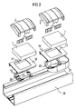
- FIG. 2 shows the assembly process of a connection unit according to of the invention on a conduit or parapet duct 18, in the fiber optic cable laid inside buildings will.
- the line duct 18 is covered in the Area in which a connection possibility is created should, with a cover 16, which on the conduit 18th is snapped on.
- This cover 16 is with a cutout 17 provided, through which the cable to be connected the conduit 18 out into the base part 1 of the connection unit is performed according to the invention.
- the attachment of the base part 1 is done either directly or with the help a mounting frame 19, which is below the cover 16 is arranged and with the help of fasteners 23 is clamped to the base part 1 to be fastened above.
- This embodiment is shown in the left part of Figure 2.
- the right part of this figure 2 shows that here the mounting frame as a container 21 with entries 22 is trained. Within this container 21 can now Excess lengths, splices and the like are stored. in the the rest of the composition is as in the already described embodiment of the left part of the figure.
- FIG. 3 shows the introduction of an optical waveguide cable 27 from below, which is intercepted in the cable interception device 28 becomes. It can be seen that this cable interception device 28 is aligned so that the optical fibers are too long 29 and 30 in opposite directions in one of the guide channel formed by the pins 9 out can be. In this way it is possible for fiber optic fibers to both side positions of the connector holders 3 while observing the minimum permissible bending radius can be guided for optical fibers. Farther can be seen that in the left connector holder 3 two individual connectors 24 and in the right connector holder 3 a double connector 11 are used to the externally guided connector 25 and 26 connected by fiber optic fibers 36 are. The connector holders 3 are also in fixations here 14 inserted, from which they are removed for service purposes can be.
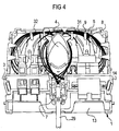
- Figure 4 finally shows the introduction of an optical fiber cable 29 in the centrally arranged cable interception device 7, from where the excess lengths are also laid 31 and 32 of the optical fibers in two directions within the guide channels can take place.
- Cable entries are initially completed by closures 13b are.
Abstract
Description
Die Erfindung betrifft eine Anschluß-Einheit für Lichtwellenleiterkabel.The invention relates to a connection unit for optical fiber cables.
Aus der europäischen Patentanmeldung EP 0 579 019 - A1 ist eine Anschlußeinheit für Lichtwellenleiter-Kabel bekannt, bei der eine Anordnung zum Ablegen von Spleißkassetten für Lichtwellenleiter innerhalb einer Kabelmuffe vorgesehen ist. Eine derartige Anordnung wird dort verwendet, wo Lichtwellenleiter-Spleiße gegen Feuchtigkeit druckdicht geschützt werden müssen. Dieser Aufwand ist jedoch nicht nötig, wenn Anschlüsse an Lichtwellenleiter-Systemen innerhalb von Gebäuden ermöglicht werden sollen.From European patent application EP 0 579 019 - A1 a connection unit for fiber optic cables known, at an arrangement for storing splice cassettes for optical fibers is provided within a cable sleeve. A such an arrangement is used where optical fiber splices protected against moisture in a pressure-tight manner have to. However, this effort is not necessary when making connections on fiber optic systems within buildings should be made possible.
Für vorliegende Erfindung stellt sich die Aufgabe, eine möglichst einfache Anschlußeinheit zum steckbaren Anschluß an Lichtwellenleiter-Systemen zu schaffen, die universell den baulichen Gegebenheiten angepaßt ist und daß damit eine schnelle und unkomplizierte Ankupplung an unter Putz, auf Putz, in Rohr- oder Leitungskanälen verlegten Lichtwellenleiter-Kabeln erstellt werden kann. Die gestellte Aufgabe wird mit einer Anschlußeinheit für Lichtwellenleiter-Kabel dadurch gelöst, daß ein Basisteil Kabelabfangvorrichtungen an zwei Stirnseiten und dazwischen in der Mitte des Basisteils aufweist, daß eine Durchführungsöffnung in der Grundplatte des Basisteils angeordnet ist, die so bemessen ist, daß mit Steckern versehene Enden von Lichtwellenleiter-Fasern durchführbar sind, daß kreisförmige Führungskanäle zur Ablegung für Überlängen von Lichtwellenleiter-Fasern um die Durchführungsöffnung herum verlaufend ausgebildet sind, daß die Stecker der Lichtwellenleiter-Fasern in Steckerhalterungen mit Befestigungsmitteln befestigt sind, daß die Steckerhalterungen in Fixierungen einsteckbar sind, daß den Steckerplätzen zugeordnete Einführungen vorgesehen sind, deren Verschlüsse bei Bedarf für den Anschluß von mit Steckern versehenen Lichtwellenleiter-Fasern entfernbar sind und daß eine abnehmbare Abdeckung über dem Basisteil aufgesetzt ist.For the present invention, the task arises, if possible simple connection unit for pluggable connection To create fiber optic systems that are universal is adapted to structural conditions and that with it a quick and uncomplicated coupling to under plaster, on Plaster, fiber optic cables laid in pipe or line ducts can be created. The task posed with a connection unit for fiber optic cables solved that a base part cable catchers on two End faces and in between in the middle of the base part, that a through opening in the base plate of the Base part is arranged, which is dimensioned so that with Plug-provided ends of fiber optic fibers can be carried out are that circular guide channels for filing for excess lengths of fiber optic fibers around the lead-through opening are trained around that the connectors of the fiber optic fibers in connector holders are fastened with fasteners that the connector brackets can be plugged in fixations that the connector slots assigned entries are provided, their closures if necessary for the connection of connectors Optical fiber fibers are removable and that one removable cover is placed over the base part.
Besonderer Vorteil an der Anschlußeinheit gemäß der Erfindung ist darin zu sehen, daß sie bei der Erstellung von Anschlüssen an innerhalb von Gebäuden bestehenden Lichtwellenleiter-Systemen mit Hilfe von Steckerkombinationen in universeller Art eingesetzt werden kann. So eignet sie sich für die Einführung und den Anschluß von Kabeln, die auf Putz, unter Putz, in Rohren oder in Leitungskanälen verlegt sind, gleichermaßen gut; denn die Einführung der Kabelenden kann seitlich, von unten wie von der Mitte her erfolgen. Dabei wird jeweils gewährleistet, daß die bei Lichtwellenleiter-Kabeln minimal zulässigen Biegeradien für Lichtwellenleiter-Fasern von mindestens 30 mm nicht unterschritten wird. Außerdem erfolgt die Führung von Lichtwellenleiter-Überlängen der anzuschließenden Lichtwellenleiter-Fasern in kreisförmig gestalteten Führungskanälen, so daß auch hier eine Unterschreitung des zulässigen Biegeradius nicht möglich ist. Die Kabeleinführungen sind zugleich als Kabelabfangvorrichtungen ausgebildet und sind dabei so angeordnet, daß die Ablage der Überlängen von Lichtwellenleiter-Fasern in zwei entgegengesetzten Richtungen bzw. Windungen erfolgen kann. Auf diese Weise ist es möglich, daß Ausgänge von Lichtwellenleiter-Fasern auch in der Nähe der Kabeleinführung vorgesehen werden können, ohne daß die Gefahr des Abknickens gegeben ist; denn die Zuführung erfolgt durch Einlegen der Lichtwellenleiter-Überlängen in einen Führungskanal in der dafür entsprechenden Einlegerichtung. Die Enden der Lichtwellenleiter-Fasern können auch bereits mit Steckern vorkonfektioniert sein, da sich in der Mitte der Anschlußeinheit eine große Durchführungsöffnung befindet, die so bemessen ist, daß die mit Steckern bereits versehenen Lichtwellenleiter-Faserenden hindurchgeführt werden können. Dabei werden immer die gleichen Kabelabfangvorrichtungen benutzt, so daß keine zusätzlichen Maßnahmen getroffen werden müssen. Auch hier werden die Überlängen in den Führungskanälen in der geeigneten Einlegerichtung abgelegt, wobei entsprechende Niederhalter dafür sorgen, daß die Lichtwellenleiter-Fasern beim Öffnen der Anschlußeinheit nicht herausspringen. Die Stecker an den Enden der Lichtwellenleiter-Fasern werden in Steckerhalterungen gefaßt, die dann in Fixierungen auf dem Basisteil der Anschlußeinheit eingesteckt, vorzugsweise eingerastet werden. Auf diese Weise ist gesichert, daß bei Montagearbeiten die mit Steckern bestückten Steckerhalterungen insgesamt aus der Anschlußeinheit entnommen werden können, um sie beispielsweise einem Spleißgerät zuzuführen. Die Stecker sind mit den Steckerhalterungen in den Fixierungen so arretiert, daß von außen zugeführte Steckanschlüsse mühelos eingesetzt werden können, wobei dann hierfür die entsprechenden Verschlüsse in den Auslässen der Anschlußeinheit je nach Bedarf entfernt werden. Das angeführte Ausführungsbeispiel zeigt im folgenden eine Gestaltung, bei der Anschlußmöglichkeiten für vier Simplex-Stecker oder für zwei Duplex-Stecker vorgesehen sind. Doch können bei Beibehaltung der sonstigen konstruktiven Ausführung auch Anschlußmöglichkeiten für andere Steckersysteme vorgesehen werden, wenn die Steckerhalterungen entsprechend angepaßt sind. Mit einer abgestimmten Abdeckblende kann die Anschlußeinheit gemäß der Erfindung auch direkt auf Leitungskanäle bzw. Rüstungskanäle aufgesetzt werden, so daß keine zusätzlichen Maßnahmen getroffen werden müssen. Dieses direkte Aufsetzen kann auch mit entsprechenden Befestigungsrahmen vorgesehen werden, mit deren Hilfe die Anschlußeinheit jeweils auf der Deckblende aufgeklemmt wird.Particular advantage of the connection unit according to the invention can be seen in the fact that they create connections on existing fiber optic systems inside buildings with the help of plug combinations in universal Type can be used. So it is suitable for the introduction and the connection of cables that are on plaster, under Plaster, in pipes or in conduits, alike Well; because the cable ends can be inserted from the side, from below as from the middle. Doing so each ensures that the fiber optic cables minimum permissible bending radii for fiber optic fibers not less than 30 mm. Also done the management of fiber optic excess lengths of the to be connected Optical fibers in a circular design Guide channels, so that here too an undercut of the permissible bending radius is not possible. The cable entries are also designed as cable interception devices and are arranged so that the storage of excess lengths of fiber optic fibers in two opposite Directions or turns can take place. That way it is possible that outputs of fiber optic fibers also in close to the cable entry can be provided without that there is a risk of kinking; because the feed is done by inserting the fiber optic excess lengths in a guide channel in the appropriate direction of insertion. The ends of the fiber optic fibers can already be pre-assembled with plugs, because in the There is a large lead-through opening in the middle of the connection unit, which is dimensioned so that the already with plugs provided fiber optic fiber ends are passed can. The same cable interception devices are always used used so that no additional measures are taken Need to become. Again, the excess lengths in the Guide channels laid in the appropriate direction of insertion, appropriate hold-down devices ensure that the optical fibers not when opening the connection unit jump out. The connectors on the ends of the fiber optic fibers are held in connector brackets, which are then in Fixations inserted on the base part of the connection unit, preferably be snapped into place. That way ensured that the assembly with plugs The plug holders are removed from the connection unit can be, for example, a splicer feed. The connectors are with the connector brackets locked in the fixations so that supplied from the outside Plug connections can be used effortlessly, then the corresponding closures in the outlets of the Connection unit can be removed as required. The above The embodiment shows a design below, in connection options for four simplex connectors or are provided for two duplex plugs. But can Retention of the other constructive execution too Connection options for other connector systems are provided be adjusted if the connector brackets are adjusted accordingly are. With a coordinated cover panel, the connection unit according to the invention also directly on line channels or armament channels, so that no additional Measures must be taken. This direct You can also put it on with the appropriate mounting frame are provided, with the help of the connection unit is clamped onto the cover panel.
Die Erfindung wird nun anhand von vier Figuren näher erläutert.
Figur 1- zeigt die Anschlußeinheit in geöffnetem Zustand.
Figur 2- zeigt die Anschlußeinheit beim Einsatz an Kabelkanälen.
Figur 3- zeigt den Verlauf der Lichtwellenleiter-Überlängen bei seitlicher Kabeleinführung.
Figur 4- zeigt den Verlauf der Lichtwellenleiter-Überlängen bei mittiger Kabeleinführung.
- Figure 1
- shows the connection unit in the open state.
- Figure 2
- shows the connection unit when used on cable ducts.
- Figure 3
- shows the course of the fiber optic excess lengths with side cable entry.
- Figure 4
- shows the course of the fiber optic excess lengths with central cable entry.
In Figur 1 werden die Einzelteile der Anschlußeinheit gemäß
der Erfindung gezeigt, wobei diese in ihrer Lage so skizziert
sind, daß sich daraus die endgültige Position erkennen läßt.
Die Anschlußeinheit besteht aus dem Basisteil 1, den Steckerhalterungen
3 für die Aufnahme der an den Enden der Lichtwellenleiter
angesetzten Stecker und dem Abdeckteil 2, das den
Innenraum überdeckt, wobei durch Einführungen 13a die einzuführenden
Stecker von Anschlußkabeln eingeführt werden können.
Das Basisteil 1 besteht aus der Grundplatte, die mittels
verschieden verlaufender Verstrebungen, Rippen und dergleichen
versteift ist. Außerdem befinden sich dort Löcher, Rasteinrichtungen
und dergleichen, durch die in an sich bekannter
Weise universelle Befestigungsmöglichkeiten gegeben sind.
Die Kabeleinführungen sind zugleich als Kabelabfangvorrichtungen
6 bzw. 7, z.B. als Klemmhalterungen ausgebildet, wobei
davon zwei Kabelabfangvorrichtungen 6 an den Stirnseiten und
eine Kabelabfangvorrichtung 7 dazwischen in der Mitte angeordnet
sind. Die beiden seitlichen Kabelabfangvorrichtungen 6
sind so gestaltet, daß die Einführung der Lichtwellenleiterkabel
von unten her wie auch in gleicher Höhe erfolgen kann,
so daß Lichtwellenleiterkabel eingeführt werden können, die
auf Putz, unter Putz oder in Rohren oder Kanälen verlegt
sind. Eine direkte Einführung kann in der mittigen Kabelabfangvorrichtung
7 vorgenommen werden. Durch Stege 8 oder/und
Stifte 9 werden Führungskanäle 5 gebildet, in denen Überlängen
von Lichtwellenleiterfasern abgelegt werden können, so
daß die Enden der Lichtwellenleiterfasern, die mit Steckern
versehen werden oder bereits sind, aus dem Basisteil 1 für
Servicezwecke herausgenommen werden können. Die Führungskanäle
5 verlaufen dabei um eine große Einführungsöffnung 4
herum, wobei diese annähernd mittig im Basisteil 1 angeordnet
ist. Der Durchmesser der kreisförmig angelegten Führungskanäle
5 ist so groß, daß eine Biegeverletzung der Lichtwellenleiter
ausgeschlossen wird (minimaler zulässiger Biegedurchmesser
≥ 30 mm). Die mittige Kabeleinführung 4 ist mit einem
Kragen 15 versehen, an dem ebenfalls wie am Rand des Basisteils
1 Niederhalter 35 angebracht sind, die ein Herausspringen
von eingelegten Lichtwellenleiterfasern verhindern.
Der Kragen 15 hat auch Auslässe 34, die auch bis zur Grundplatte
und hin bis zur jeweiligen Kabelabfangvorrichtung 6
ausgebrochen werden können, so daß hierdurch die von unten
eingeführten Lichtwellenleiterkabel nach oben geführt werden
können. Diese Kabeleinführungsöffnung 4 ist so groß und so
geformt, daß auch bereits mit Steckern versehene Lichtwellenleiterkabel
bzw. Lichtwellenleiterfasern eingeführt werden
können, wobei zunächst die Lichtwellenleiterkabel zu den
Kabelabfangvorrichtungen 6 geführt werden. Von dort erfolgt
dann die Einlegung der einzelnen Lichtwellenleiterfasern nach
Einführung durch die Kabeleinführungsöffnung 4 in die
Führungskanäle 5. Die Faserenden der eingelegten
Lichtwellenleiterkabel werden oder sind mit Steckern versehen,
die nun in Aufnahmen 10 von herausnehmbaren Steckerhalterungen
3 mittels Befestigungsmitteln 33, zum Beispiel Klemmen
oder Schrauben, befestigt werden. Durch die Bezeichnung
12 innerhalb der Abdeckung 2 ist die Fassung der Lichtwellenleiterfasern
in einem Stecker skizziert. Die Steckerhalterungen
3 werden in Fixierungen 14, zum Beispiel in Nutenführungen,
eingesteckt, so daß sie dort in ihrer Lage mechanisch
festgelegt sind. Je nach Bedarf werden die Verschlüsse 13b am
Basisteil 1 entfernt, so daß dann von außen die Stecker der
anzuschließenden Lichtwellenleiterkabel eingeführt und gesteckt
werden können. Die Steckerhalterungen 3 können den jeweils
verwendeten Steckern angepaßt sein und zum Beispiel
Aufnahmen 10 für zwei oder einen Stecker enthalten. Schließlich
ist auf dem Basisteil 1 noch die mittige Kabeleinführung
der Kabelabfangvorrichtung 7 erkennbar, in der zum Beispiel
ein auf Putz verlegtes Lichtwellenleiterkabel in an sich bekannter
Weise eingeführt und abgefangen wird. Die Abdeckblende
2 kann auf das Basisteil 1 aufgesetzt und vorzugsweise
aufgerastet werden.In Figure 1, the individual parts of the connection unit according to
shown the invention, this outlined in its position
are that the final position can be recognized.
The connection unit consists of the
Figur 2 zeigt den Montagevorgang einer Anschlußeinheit gemäß
der Erfindung auf einem Leitungs- bzw. Brüstungskanal 18, in
dem innerhalb von Gebäuden Lichtwellenleiterkabel verlegt
werden. Die Abdeckung des Leitungskanales 18 erfolgt in dem
Bereich, in dem eine Anschlußmöglichkeit geschaffen werden
soll, mit einer Abdeckblende 16, die auf dem Leitungskanal 18
aufgerastet wird. Diese Abdeckblende 16 ist mit einem Ausschnitt
17 versehen, durch den das anzuschließende Kabel aus
dem Leitungskanal 18 heraus in das Basisteil 1 der Anschlußeinheit
gemäß der Erfindung geführt wird. Die Befestigung
des Basisteils 1 erfolgt entweder direkt oder mit Hilfe
eines Befestigungsrahmens 19, der unterhalb der Abdeckblende
16 angeordnet wird und der mit Hilfe von Befestigungsmitteln
23 am oberhalb zu befestigenden Basisteil 1 angeklemmt wird.
Seitliche Einführungskanäle 20 im Befestigungsrahmen 19 ermöglichen
eine geordnete Einführung des jeweilig auszuführenden
Lichtwellenleiterkabels bzw. der Lichtwellenleiterfasern.
Diese Ausführung ist im linken Teil dieser Figur 2 dargestellt.
Im rechten Teil dieser Figur 2 ist gezeigt, daß hier
der Befestigungsrahmen als Behälter 21 mit Einführungen 22
ausgebildet ist. Innerhalb dieses Behälters 21 können nun bereits
Überlängen, Spleiße und dergleichen abgelegt werden. Im
übrigen erfolgt die weitere Zusammensetzung wie im bereits
beschriebenen Ausführungsbeispiel des linken Figurenteils.
Ergänzend sind noch die einzuführenden Steckerhalterungen 3
und die Abdeckungen 2 dargestellt, die den weiteren Montageablauf
andeuten. Figure 2 shows the assembly process of a connection unit according to
of the invention on a conduit or
Figur 3 zeigt die Einführung eines Lichtwellenleiterkabels 27
von unten her, das in der Kabelabfangvorrichtung 28 abgefangen
wird. Dabei ist ersichtlich, daß diese Kabelabfangvorrichtung
28 so ausgerichtet ist, daß die Lichtwellenleiterüberlängen
29 und 30 in entgegengesetzten Richtungen in
einem der durch die Stifte 9 gebildeten Führungskanal geführt
werden können. Auf diese Weise ist es möglich, daß Lichtwellenleiterfasern
zu beiden seitlichen Positionen der Steckerhalterungen
3 unter Einhaltung des minimal zulässigen Biegeradius
für Lichtwellenleiter geführt werden können. Weiterhin
ist erkennbar, daß in der linken Steckerhalterung 3 zwei Einzelstecker
24 und in der rechten Steckerhalterung 3 ein Doppelstecker
11 verwendet sind, an die von außen geführte Stecker
25 bzw. 26 von Lichtwellenleiterfasern 36 angeschlossen
sind. Die Steckerhalterungen 3 sind auch hier in Fixierungen
14 eingesteckt, aus denen sie für Servicezwecke entnommen
werden können.FIG. 3 shows the introduction of an
Figur 4 zeigt schließlich die Einführung eines Lichtwellenleiterkabels
29 in der mittig angeordneten Kabelabfangvorrichtung
7, von wo aus ebenfalls die Verlegung der Überlängen
31 und 32 der Lichtwellenleiterfasern in zwei Richtungen innerhalb
der Führungskanäle erfolgen kann. Im übrigen sind
hier die gleichen Verhältnisse gegeben, wobei hier die
Kabeleinführungen zunächst noch durch Verschlüsse 13b abgeschlossen
sind.Figure 4 finally shows the introduction of an
Claims (17)
dadurch gekennzeichnet,
daß ein Basisteil (1) Kabelabfangungen (6, 7, 28) an zwei Stirnseiten und dazwischen in der Mitte des Basisteils (1) aufweist, daß eine Durchführungsöffnung (4) in der Grundplatte des Basisteils (1) angeordnet ist, die so bemessen ist, daß mit Steckern (11, 24) versehene Enden von Lichtwellenleiterfasern (29, 30, 31, 32) durchführbar sind, daß kreisförmige Führungskanäle (5) zur Ablegung für Überlängen von Lichtwellenleiterfasern (29, 30, 31, 32) um die Durchführungsöffnung (4) herum verlaufend ausgebildet sind, daß die Stecker (11, 24) der Lichtwellenleiterfasern (29, 30, 31, 32) in Steckerhalterungen (3) mit Befestigungsmitteln (33) befestigt sind, daß die Steckerhalterungen (3) in Fixierungen (14) einsteckbar sind, daß den Steckerplätzen zugeordnete Einführungen (13a) vorgesehen sind, deren Verschlüsse (13b) bei Bedarf für den Anschluß von mit Steckern (25, 26) versehenen Lichtwellenleiterfasern (36) entfernbar sind und daß eine abnehmbare Abdeckung (2) über dem Basisteil (1) aufgesetzt ist.Connection unit for fiber optic cables,
characterized,
that a base part (1) has cable clamps (6, 7, 28) on two end faces and in between in the middle of the base part (1), that a through opening (4) is arranged in the base plate of the base part (1), which is dimensioned so that ends of optical waveguide fibers (29, 30, 31, 32) provided with plugs (11, 24) can be passed through, that circular guide channels (5) for storing excess lengths of optical waveguide fibers (29, 30, 31, 32) around the lead-through opening ( 4) are designed so that the plugs (11, 24) of the optical fibers (29, 30, 31, 32) are fastened in plug holders (3) with fastening means (33), that the plug holders (3) in fixings (14) can be plugged in that the plug-in entries (13a) are provided, the closures (13b) of which can be removed if necessary for the connection of plugs (25, 26) provided with optical fibers (36) and that a removable cover (2) can be removed the base part (1) is placed.
dadurch gekennzeichnet,
daß die Abdeckung (2) rastend aufgesetzt ist.Connection unit according to claim 1,
characterized,
that the cover (2) is put into place.
dadurch gekennzeichnet,
daß die Führungskanäle (5) auf der Grundplatte durch Stege (8) und/oder Stifte (9) gebildet sind. Connection unit according to one of the preceding claims,
characterized,
that the guide channels (5) on the base plate by webs (8) and / or pins (9) are formed.
dadurch gekennzeichnet,
daß die Kabeleinführungen mit den Kabelabfangvorrichtungen (6, 7) so angeordnet und ausgerichtet sind, daß die Oberlängen der Lichtwellenleiterfasern (29, 30,31, 32) in entgegengerichteten Windungen in die Führungskanäle (5) einlegbar sind.Connection unit according to one of the preceding claims,
characterized,
that the cable entries with the cable interception devices (6, 7) are arranged and aligned so that the upper lengths of the optical fibers (29, 30, 31, 32) can be inserted in opposite turns in the guide channels (5).
dadurch gekennzeichnet,
daß der Radius der Führungskanäle (5) mindestens dem minimal zulässigen Biegeradius der Lichtwellenleiterfasern von mindestens 30 mm entspricht.Connection unit according to one of the preceding claims,
characterized,
that the radius of the guide channels (5) corresponds at least to the minimum permissible bending radius of the optical fibers of at least 30 mm.
dadurch gekennzeichnet,
daß die Steckerhalterungen (3) Aufnahmen (10) für zwei einzelne Stecker (24) aufweisen.Connection unit according to one of the preceding claims,
characterized,
that the connector holders (3) have receptacles (10) for two individual connectors (24).
dadurch gekennzeichnet,
daß die Steckerhalterung eine Aufnahme (10) für einen Doppelstecker (11) aufweist.Connection unit according to one of claims 1 to 5,
characterized,
that the connector holder has a receptacle (10) for a double connector (11).
dadurch gekennzeichnet,
daß das Basisteil (1) Befestigungsmittel für die Wandmontage aufweist.Connection unit according to one of the preceding claims,
characterized,
that the base part (1) has fastening means for wall mounting.
dadurch gekennzeichnet,
daß das Basisteil (1) auf einer Abdeckblende (16) eines Leitungskanals (18) befestigt ist, wobei die Abdeckblende (16) einen Ausschnitt (17) zur Durchführung des Lichtwellenleiterkabels aufweist. Connection unit according to one of the preceding claims,
characterized,
that the base part (1) is attached to a cover panel (16) of a conduit (18), the cover panel (16) having a cutout (17) for the passage of the optical waveguide cable.
dadurch gekennzeichnet,
daß das Basisteil (1) mit Hilfe eines Befestigungsrahmens (19) auf der Abdeckblende (16) angeklemmt ist.Connection unit according to claim 9,
characterized,
that the base part (1) is clamped on the cover panel (16) with the aid of a fastening frame (19).
dadurch gekennzeichnet,
daß der Befestigungsrahmen als Behälter (21) mit einer Einführung (22) zur Aufnahme von Spleißen und/oder Überlängen und Lichtwellenleiterfasern ausgebildet ist.Connection unit according to claim 10,
characterized,
that the mounting frame is designed as a container (21) with an introduction (22) for receiving splices and / or excess lengths and optical fibers.
dadurch gekennzeichnet,
daß die Abdeckblende (16) auf den Leitungskanal (18) aufrastbar ist.Connection unit according to one of claims 9 to 11,
characterized,
that the cover (16) can be snapped onto the conduit (18).
dadurch gekennzeichnet,
daß das Kabel bei Aufputzmontage durch die mittig angeordnete Kabelabfangvorrichtung (7) eingeführt ist.Connection unit according to one of the preceding claims,
characterized,
that the cable is inserted during surface mounting through the centrally arranged cable interception device (7).
dadurch gekennzeichnet,
daß das Kabel bei Montage unter Putz oder bei Montage auf einem Leitungskanal (18) durch eine der seitlich angeordneten Kabelabfangvorrichtungen (6) eingeführt und abgefangen ist.Connection unit according to one of claims 1 to 12,
characterized,
that the cable is inserted and intercepted by one of the laterally arranged cable interception devices (6) when installed under plaster or when installed on a conduit (18).
dadurch gekennzeichnet,
daß ein mit Kabelsteckern (11, 24) bereits vorkonfektioniertes Ende eines Lichtwellenleiterkabels in einer seitlichen Kabelabfangvorrichtung (6) fixiert ist, von unten her durch einen ausgebrochenen Auslaß (34) und die Durchführungsöffnung (4) eingeführt ist, daß dann die Überlängen der Lichtwellenleiterfasern (29, 30) dieses Lichtwellenleiterkabels (27) in den Führungskanälen (5) abgelegt sind, daß die Kabelstecker (11, 24) in den Steckerhalterungen (3) befestigt sind und daß die Steckerhalterungen (3) in den Fixierungen (14) angeordnet sind.Connection unit according to one of the preceding claims,
characterized,
that an end of an optical fiber cable that is already pre-assembled with cable plugs (11, 24) is fixed in a lateral cable interception device (6), is inserted from below through a broken-out outlet (34) and the lead-through opening (4), so that the excess lengths of the optical fiber fibers ( 29, 30) of this fiber optic cable (27) are stored in the guide channels (5), that the cable connectors (11, 24) are fastened in the connector holders (3) and that the connector holders (3) are arranged in the fixings (14).
dadurch gekennzeichnet,
daß die Durchführungsöffnung (4 ) mit einem umlaufenden Kragen (15) versehen ist, bei dem seitliche Auslässe (34) bis zu den seitlichen Kabelabfangvorrichtungen (6) ausbrechbar sind.Connection unit according to one of the preceding claims,
characterized,
that the feed-through opening (4) is provided with a circumferential collar (15), in which lateral outlets (34) can be broken out as far as the lateral cable interception devices (6).
dadurch gekennzeichnet,
daß die Aufnahmen (10) der Steckerhalterungen (3) den verwendeten Steckern (11, 24) anpaßbar sind.Connection unit according to one of the preceding claims,
characterized,
that the receptacles (10) of the plug holders (3) can be adapted to the plugs (11, 24) used.
Applications Claiming Priority (2)
| Application Number | Priority Date | Filing Date | Title |
|---|---|---|---|
| DE19648294 | 1996-11-21 | ||
| DE19648294 | 1996-11-21 |
Publications (3)
| Publication Number | Publication Date |
|---|---|
| EP0844504A2 true EP0844504A2 (en) | 1998-05-27 |
| EP0844504A3 EP0844504A3 (en) | 1999-03-31 |
| EP0844504B1 EP0844504B1 (en) | 2003-04-16 |
Family
ID=7812405
Family Applications (1)
| Application Number | Title | Priority Date | Filing Date |
|---|---|---|---|
| EP97119046A Expired - Lifetime EP0844504B1 (en) | 1996-11-21 | 1997-10-31 | Connection box for optical cables |
Country Status (4)
| Country | Link |
|---|---|
| EP (1) | EP0844504B1 (en) |
| AT (1) | ATE237820T1 (en) |
| DE (1) | DE59709848D1 (en) |
| ES (1) | ES2196235T3 (en) |
Cited By (20)
| Publication number | Priority date | Publication date | Assignee | Title |
|---|---|---|---|---|
| WO2005088373A1 (en) * | 2004-03-08 | 2005-09-22 | Adc Telecommunications, Inc. | Fiber access terminal |
| USRE40358E1 (en) | 1998-07-27 | 2008-06-03 | Adc Telecommunications, Inc. | Outside plant fiber distribution apparatus and method |
| FR2916284A1 (en) * | 2007-05-14 | 2008-11-21 | Free Soc Par Actions Simplifie | FIBER OPTIC PROTECTION COVER |
| US7477824B2 (en) | 2006-04-05 | 2009-01-13 | Adc Telecommunications, Inc. | Universal bracket for mounting a drop terminal |
| EP2045636A1 (en) * | 2007-10-04 | 2009-04-08 | Nexans | Optical socket for telecommunication network |
| US7653282B2 (en) | 2004-01-27 | 2010-01-26 | Corning Cable Systems Llc | Multi-port optical connection terminal |
| US7680388B2 (en) | 2004-11-03 | 2010-03-16 | Adc Telecommunications, Inc. | Methods for configuring and testing fiber drop terminals |
| US7740409B2 (en) | 2007-09-19 | 2010-06-22 | Corning Cable Systems Llc | Multi-port optical connection terminal |
| US7805044B2 (en) | 2004-11-03 | 2010-09-28 | Adc Telecommunications, Inc. | Fiber drop terminal |
| US7844158B2 (en) | 2007-10-09 | 2010-11-30 | Adc Telecommunications, Inc. | Mini drop terminal |
| WO2011019574A1 (en) * | 2009-08-13 | 2011-02-17 | Commscope, Inc. Of North Carolina | Fiber management component |
| US7903923B2 (en) | 2007-10-09 | 2011-03-08 | Adc Telecommunications, Inc. | Drop terminal releasable engagement mechanism |
| EP2400330A1 (en) * | 2010-06-22 | 2011-12-28 | CCS Technology, Inc. | Apparatus for handling optical waveguides |
| FR2979438A1 (en) * | 2011-08-30 | 2013-03-01 | Legrand France | Coiling device for use in coiling accessory of wall box of connection device for coiling optical fiber, has recess forming space to receive cable to be coiled from coiling station, where device is maintained in opening of multipost support |
| US8755663B2 (en) | 2010-10-28 | 2014-06-17 | Corning Cable Systems Llc | Impact resistant fiber optic enclosures and related methods |
| US8873926B2 (en) | 2012-04-26 | 2014-10-28 | Corning Cable Systems Llc | Fiber optic enclosures employing clamping assemblies for strain relief of cables, and related assemblies and methods |
| US9069151B2 (en) | 2011-10-26 | 2015-06-30 | Corning Cable Systems Llc | Composite cable breakout assembly |
| CN101539650B (en) * | 2004-03-08 | 2016-01-27 | Adc电信公司 | Fiber access terminal |
| DE102016101333A1 (en) * | 2016-01-26 | 2017-07-27 | "Durable" Hunke & Jochheim Gmbh & Co. Kommanditgesellschaft | Cable holder, cable holder system and device holder system |
| US11899262B2 (en) | 2019-03-29 | 2024-02-13 | Commscope Technologies Llc | Fiber management components for telelcommunications closures |
Citations (7)
| Publication number | Priority date | Publication date | Assignee | Title |
|---|---|---|---|---|
| US4976510A (en) * | 1989-11-20 | 1990-12-11 | Siecor Corporation | Communication outlet |
| US5109467A (en) * | 1991-02-27 | 1992-04-28 | Keptel, Inc. | Interconnect cabinet for optical fibers |
| EP0490609A2 (en) * | 1990-12-13 | 1992-06-17 | BICC Public Limited Company | Optical fibre termination device |
| WO1992022842A2 (en) * | 1991-06-18 | 1992-12-23 | British Telecommunications Public Limited Company | Optical fibre connection equipment |
| DE9304131U1 (en) * | 1993-02-16 | 1993-05-13 | Walter Rose Gmbh & Co Kg, 5800 Hagen, De | |
| DE4218378A1 (en) * | 1992-06-04 | 1993-12-16 | Rose Walter Gmbh & Co Kg | Optical cable connection box with additional frame and cover - provides space within wall mounted housing for insertion of additional optical waveguides into enlarged vol. enclosed |
| US5335304A (en) * | 1993-04-30 | 1994-08-02 | The United States Of America As Represented By The Secretary Of The Army | Connector distribution assembly for a fiber optic detector system |
-
1997
- 1997-10-31 DE DE59709848T patent/DE59709848D1/en not_active Expired - Lifetime
- 1997-10-31 AT AT97119046T patent/ATE237820T1/en not_active IP Right Cessation
- 1997-10-31 EP EP97119046A patent/EP0844504B1/en not_active Expired - Lifetime
- 1997-10-31 ES ES97119046T patent/ES2196235T3/en not_active Expired - Lifetime
Patent Citations (9)
| Publication number | Priority date | Publication date | Assignee | Title |
|---|---|---|---|---|
| US4976510A (en) * | 1989-11-20 | 1990-12-11 | Siecor Corporation | Communication outlet |
| US4976510B1 (en) * | 1989-11-20 | 1994-09-13 | Siecor Corp | Communication outlet |
| US4976510B2 (en) * | 1989-11-20 | 1995-05-09 | Siecor Corp | Communication outlet |
| EP0490609A2 (en) * | 1990-12-13 | 1992-06-17 | BICC Public Limited Company | Optical fibre termination device |
| US5109467A (en) * | 1991-02-27 | 1992-04-28 | Keptel, Inc. | Interconnect cabinet for optical fibers |
| WO1992022842A2 (en) * | 1991-06-18 | 1992-12-23 | British Telecommunications Public Limited Company | Optical fibre connection equipment |
| DE4218378A1 (en) * | 1992-06-04 | 1993-12-16 | Rose Walter Gmbh & Co Kg | Optical cable connection box with additional frame and cover - provides space within wall mounted housing for insertion of additional optical waveguides into enlarged vol. enclosed |
| DE9304131U1 (en) * | 1993-02-16 | 1993-05-13 | Walter Rose Gmbh & Co Kg, 5800 Hagen, De | |
| US5335304A (en) * | 1993-04-30 | 1994-08-02 | The United States Of America As Represented By The Secretary Of The Army | Connector distribution assembly for a fiber optic detector system |
Cited By (41)
| Publication number | Priority date | Publication date | Assignee | Title |
|---|---|---|---|---|
| USRE42258E1 (en) | 1998-07-27 | 2011-03-29 | Adc Telecommunications, Inc. | Outside plant fiber distribution apparatus and method |
| USRE40358E1 (en) | 1998-07-27 | 2008-06-03 | Adc Telecommunications, Inc. | Outside plant fiber distribution apparatus and method |
| USRE41777E1 (en) | 1998-07-27 | 2010-09-28 | Adc Telecommunications, Inc. | Outside plant fiber distribution apparatus and method |
| US7653282B2 (en) | 2004-01-27 | 2010-01-26 | Corning Cable Systems Llc | Multi-port optical connection terminal |
| EP2128673A3 (en) * | 2004-03-08 | 2010-01-06 | ADC Telecommunications, Inc. | Fiber access terminal |
| US7397997B2 (en) | 2004-03-08 | 2008-07-08 | Adc Telecommunications, Inc. | Fiber access terminal |
| CN101539650B (en) * | 2004-03-08 | 2016-01-27 | Adc电信公司 | Fiber access terminal |
| US8363999B2 (en) | 2004-03-08 | 2013-01-29 | Adc Telecommunications, Inc. | Fiber access terminal |
| USRE43762E1 (en) | 2004-03-08 | 2012-10-23 | Adc Telecommunications, Inc. | Fiber access terminal |
| EP2128673A2 (en) * | 2004-03-08 | 2009-12-02 | ADC Telecommunications, Inc. | Fiber access terminal |
| WO2005088373A1 (en) * | 2004-03-08 | 2005-09-22 | Adc Telecommunications, Inc. | Fiber access terminal |
| US7941027B2 (en) | 2004-03-08 | 2011-05-10 | Adc Telecommunications, Inc. | Fiber access terminal |
| US7292763B2 (en) | 2004-03-08 | 2007-11-06 | Adc Telecommunications, Inc. | Fiber access terminal |
| US11567278B2 (en) | 2004-11-03 | 2023-01-31 | Commscope Technologies Llc | Fiber drop terminal |
| US7805044B2 (en) | 2004-11-03 | 2010-09-28 | Adc Telecommunications, Inc. | Fiber drop terminal |
| US9851522B2 (en) | 2004-11-03 | 2017-12-26 | Commscope Technologies Llc | Fiber drop terminal |
| US10042136B2 (en) | 2004-11-03 | 2018-08-07 | Commscope Technologies Llc | Fiber drop terminal |
| US10890729B2 (en) | 2004-11-03 | 2021-01-12 | Commscope Technologies Llc | Fiber drop terminal and bracket |
| US7680388B2 (en) | 2004-11-03 | 2010-03-16 | Adc Telecommunications, Inc. | Methods for configuring and testing fiber drop terminals |
| US8218935B2 (en) | 2006-04-05 | 2012-07-10 | Adc Telecommunications, Inc. | Universal bracket for mounting a drop terminal |
| US7844160B2 (en) | 2006-04-05 | 2010-11-30 | Adc Telecommunications, Inc. | Universal bracket for mounting a drop terminal |
| US7477824B2 (en) | 2006-04-05 | 2009-01-13 | Adc Telecommunications, Inc. | Universal bracket for mounting a drop terminal |
| FR2916284A1 (en) * | 2007-05-14 | 2008-11-21 | Free Soc Par Actions Simplifie | FIBER OPTIC PROTECTION COVER |
| WO2008149017A1 (en) * | 2007-05-14 | 2008-12-11 | Free | Optical fibre protection hood |
| US7740409B2 (en) | 2007-09-19 | 2010-06-22 | Corning Cable Systems Llc | Multi-port optical connection terminal |
| EP2045636A1 (en) * | 2007-10-04 | 2009-04-08 | Nexans | Optical socket for telecommunication network |
| FR2922032A1 (en) * | 2007-10-04 | 2009-04-10 | Nexans Sa | OPTICAL OUTLET FOR TELECOMMUNICATION NETWORK. |
| US8213761B2 (en) | 2007-10-09 | 2012-07-03 | Adc Telecommunications | Mini drop terminal |
| US7903923B2 (en) | 2007-10-09 | 2011-03-08 | Adc Telecommunications, Inc. | Drop terminal releasable engagement mechanism |
| US7844158B2 (en) | 2007-10-09 | 2010-11-30 | Adc Telecommunications, Inc. | Mini drop terminal |
| US8422846B2 (en) | 2009-08-13 | 2013-04-16 | Commscope, Inc. Of North Carolina | Fiber management component |
| AU2010282782B2 (en) * | 2009-08-13 | 2014-05-01 | Commscope, Inc. Of North Carolina | Fiber management component |
| WO2011019574A1 (en) * | 2009-08-13 | 2011-02-17 | Commscope, Inc. Of North Carolina | Fiber management component |
| EP2400330A1 (en) * | 2010-06-22 | 2011-12-28 | CCS Technology, Inc. | Apparatus for handling optical waveguides |
| US8755663B2 (en) | 2010-10-28 | 2014-06-17 | Corning Cable Systems Llc | Impact resistant fiber optic enclosures and related methods |
| FR2979438A1 (en) * | 2011-08-30 | 2013-03-01 | Legrand France | Coiling device for use in coiling accessory of wall box of connection device for coiling optical fiber, has recess forming space to receive cable to be coiled from coiling station, where device is maintained in opening of multipost support |
| US9069151B2 (en) | 2011-10-26 | 2015-06-30 | Corning Cable Systems Llc | Composite cable breakout assembly |
| US8873926B2 (en) | 2012-04-26 | 2014-10-28 | Corning Cable Systems Llc | Fiber optic enclosures employing clamping assemblies for strain relief of cables, and related assemblies and methods |
| DE102016101333A1 (en) * | 2016-01-26 | 2017-07-27 | "Durable" Hunke & Jochheim Gmbh & Co. Kommanditgesellschaft | Cable holder, cable holder system and device holder system |
| EP3203351A1 (en) | 2016-01-26 | 2017-08-09 | "Durable" Hunke & Jochheim Gmbh & Co. Kommanditgesellschaft | Cable holder, cable holder system and device holder system |
| US11899262B2 (en) | 2019-03-29 | 2024-02-13 | Commscope Technologies Llc | Fiber management components for telelcommunications closures |
Also Published As
| Publication number | Publication date |
|---|---|
| ES2196235T3 (en) | 2003-12-16 |
| DE59709848D1 (en) | 2003-05-22 |
| EP0844504A3 (en) | 1999-03-31 |
| ATE237820T1 (en) | 2003-05-15 |
| EP0844504B1 (en) | 2003-04-16 |
Similar Documents
| Publication | Publication Date | Title |
|---|---|---|
| EP0844504B1 (en) | Connection box for optical cables | |
| DE3025700C2 (en) | Sleeve for multi-pair fiber optic cables | |
| DE102005052882B4 (en) | Method and device for coupling optical waveguides | |
| DE3133586C2 (en) | Splice carrier for fiber optic cables | |
| EP0715196B1 (en) | Splice tray module for optical fibers | |
| EP0872750B1 (en) | Junction box with a holding device for cassettes for storing optical fibres and their splices | |
| EP1891474A1 (en) | Optical waveguide distribution device | |
| DE3347621A1 (en) | DISTRIBUTION RACK FOR FIBERGLASS CABLE ENDS | |
| EP0582744A1 (en) | Communication path for arrangements provided with light wave guides | |
| DE60123059T2 (en) | BUILDINGS TO BE USED IN BUILDINGS TO CONNECT BETWEEN OPTICAL FIBERS AND WORKPLACES | |
| EP0579019A1 (en) | Optical fibre splice cassette lay device for cable muff | |
| DE60003069T2 (en) | GUIDE OF FIBERGLASS | |
| EP0883004A1 (en) | Cassette system for cable coupling boxes or distribution frames | |
| EP1904881B1 (en) | Optical fiber distribution device | |
| AT408698B (en) | Fibre separating (distributing, dividing) head | |
| DE4405666A1 (en) | Universal connection unit for optical fibers | |
| EP0503614B1 (en) | Strain relief device for signal transmission cables, specially for glas fiber cables | |
| DE3542724C2 (en) | End set for an optical cable | |
| EP2176697B1 (en) | Junction box for fibre-optical cables | |
| DE2621823A1 (en) | Excess lighting cable storage unit - uses cylindrical reels with circumferential adjacent grooves and has clamps for splicing elements | |
| DE202009014308U1 (en) | Pigtail handling device and optical fiber distribution device | |
| DE4439853A1 (en) | Junction unit for optic fibres | |
| DE19648780C2 (en) | Optical junction box arrangement | |
| EP0582745A1 (en) | Cabling and installation system for arrangements provided with light wave guides | |
| DE10113528A1 (en) | Utilisation of cable guide module for controlled cable guidance by fitting to plug-in component group carrier |
Legal Events
| Date | Code | Title | Description |
|---|---|---|---|
| PUAI | Public reference made under article 153(3) epc to a published international application that has entered the european phase |
Free format text: ORIGINAL CODE: 0009012 |
|
| AK | Designated contracting states |
Kind code of ref document: A2 Designated state(s): AT BE CH DE DK ES FR GB LI NL SE |
|
| PUAL | Search report despatched |
Free format text: ORIGINAL CODE: 0009013 |
|
| AK | Designated contracting states |
Kind code of ref document: A3 Designated state(s): AT BE CH DE DK ES FI FR GB GR IE IT LI LU MC NL PT SE |
|
| 17P | Request for examination filed |
Effective date: 19990419 |
|
| AKX | Designation fees paid |
Free format text: AT BE CH DE DK ES FR GB LI NL SE |
|
| RAP1 | Party data changed (applicant data changed or rights of an application transferred) |
Owner name: RXS GESELLSCHAFT FUER VERMOEGENSVERWALTUNG MBH |
|
| 17Q | First examination report despatched |
Effective date: 20010424 |
|
| RAP1 | Party data changed (applicant data changed or rights of an application transferred) |
Owner name: RXS GESELLSCHAFT FUER VERMOEGENSVERWALTUNG MBH |
|
| GRAH | Despatch of communication of intention to grant a patent |
Free format text: ORIGINAL CODE: EPIDOS IGRA |
|
| GRAH | Despatch of communication of intention to grant a patent |
Free format text: ORIGINAL CODE: EPIDOS IGRA |
|
| GRAA | (expected) grant |
Free format text: ORIGINAL CODE: 0009210 |
|
| RAP1 | Party data changed (applicant data changed or rights of an application transferred) |
Owner name: CCS TECHNOLOGY, INC. |
|
| AK | Designated contracting states |
Designated state(s): AT BE CH DE DK ES FR GB LI NL SE |
|
| PG25 | Lapsed in a contracting state [announced via postgrant information from national office to epo] |
Ref country code: NL Free format text: LAPSE BECAUSE OF FAILURE TO SUBMIT A TRANSLATION OF THE DESCRIPTION OR TO PAY THE FEE WITHIN THE PRESCRIBED TIME-LIMIT Effective date: 20030416 |
|
| REG | Reference to a national code |
Ref country code: GB Ref legal event code: FG4D Free format text: NOT ENGLISH |
|
| REG | Reference to a national code |
Ref country code: CH Ref legal event code: EP |
|
| REF | Corresponds to: |
Ref document number: 59709848 Country of ref document: DE Date of ref document: 20030522 Kind code of ref document: P |
|
| PG25 | Lapsed in a contracting state [announced via postgrant information from national office to epo] |
Ref country code: SE Free format text: LAPSE BECAUSE OF FAILURE TO SUBMIT A TRANSLATION OF THE DESCRIPTION OR TO PAY THE FEE WITHIN THE PRESCRIBED TIME-LIMIT Effective date: 20030716 Ref country code: DK Free format text: LAPSE BECAUSE OF FAILURE TO SUBMIT A TRANSLATION OF THE DESCRIPTION OR TO PAY THE FEE WITHIN THE PRESCRIBED TIME-LIMIT Effective date: 20030716 |
|
| GBT | Gb: translation of ep patent filed (gb section 77(6)(a)/1977) | ||
| NLV1 | Nl: lapsed or annulled due to failure to fulfill the requirements of art. 29p and 29m of the patents act | ||
| PG25 | Lapsed in a contracting state [announced via postgrant information from national office to epo] |
Ref country code: LI Free format text: LAPSE BECAUSE OF NON-PAYMENT OF DUE FEES Effective date: 20031031 Ref country code: CH Free format text: LAPSE BECAUSE OF NON-PAYMENT OF DUE FEES Effective date: 20031031 Ref country code: BE Free format text: LAPSE BECAUSE OF NON-PAYMENT OF DUE FEES Effective date: 20031031 Ref country code: AT Free format text: LAPSE BECAUSE OF NON-PAYMENT OF DUE FEES Effective date: 20031031 |
|
| REG | Reference to a national code |
Ref country code: ES Ref legal event code: FG2A Ref document number: 2196235 Country of ref document: ES Kind code of ref document: T3 |
|
| ET | Fr: translation filed | ||
| PLBE | No opposition filed within time limit |
Free format text: ORIGINAL CODE: 0009261 |
|
| STAA | Information on the status of an ep patent application or granted ep patent |
Free format text: STATUS: NO OPPOSITION FILED WITHIN TIME LIMIT |
|
| 26N | No opposition filed |
Effective date: 20040119 |
|
| BERE | Be: lapsed |
Owner name: *CCS TECHNOLOGY INC. Effective date: 20031031 |
|
| REG | Reference to a national code |
Ref country code: CH Ref legal event code: PL |
|
| REG | Reference to a national code |
Ref country code: FR Ref legal event code: TP Ref country code: FR Ref legal event code: CD |
|
| PGFP | Annual fee paid to national office [announced via postgrant information from national office to epo] |
Ref country code: FR Payment date: 20121107 Year of fee payment: 16 Ref country code: DE Payment date: 20121029 Year of fee payment: 16 |
|
| PGFP | Annual fee paid to national office [announced via postgrant information from national office to epo] |
Ref country code: ES Payment date: 20121026 Year of fee payment: 16 Ref country code: GB Payment date: 20121025 Year of fee payment: 16 |
|
| GBPC | Gb: european patent ceased through non-payment of renewal fee |
Effective date: 20131031 |
|
| REG | Reference to a national code |
Ref country code: DE Ref legal event code: R119 Ref document number: 59709848 Country of ref document: DE Effective date: 20140501 |
|
| PG25 | Lapsed in a contracting state [announced via postgrant information from national office to epo] |
Ref country code: GB Free format text: LAPSE BECAUSE OF NON-PAYMENT OF DUE FEES Effective date: 20131031 |
|
| REG | Reference to a national code |
Ref country code: FR Ref legal event code: ST Effective date: 20140630 |
|
| PG25 | Lapsed in a contracting state [announced via postgrant information from national office to epo] |
Ref country code: FR Free format text: LAPSE BECAUSE OF NON-PAYMENT OF DUE FEES Effective date: 20131031 Ref country code: DE Free format text: LAPSE BECAUSE OF NON-PAYMENT OF DUE FEES Effective date: 20140501 |
|
| REG | Reference to a national code |
Ref country code: ES Ref legal event code: FD2A Effective date: 20141107 |
|
| PG25 | Lapsed in a contracting state [announced via postgrant information from national office to epo] |
Ref country code: ES Free format text: LAPSE BECAUSE OF NON-PAYMENT OF DUE FEES Effective date: 20131101 |