EP0844963B1 - Improvements in or relating to seabed enclosures - Google Patents
Improvements in or relating to seabed enclosures Download PDFInfo
- Publication number
- EP0844963B1 EP0844963B1 EP96927137A EP96927137A EP0844963B1 EP 0844963 B1 EP0844963 B1 EP 0844963B1 EP 96927137 A EP96927137 A EP 96927137A EP 96927137 A EP96927137 A EP 96927137A EP 0844963 B1 EP0844963 B1 EP 0844963B1
- Authority
- EP
- European Patent Office
- Prior art keywords
- container
- seabed
- enclosure
- silt
- sand
- Prior art date
- Legal status (The legal status is an assumption and is not a legal conclusion. Google has not performed a legal analysis and makes no representation as to the accuracy of the status listed.)
- Expired - Lifetime
Links
Images


Classifications
-
- G—PHYSICS
- G01—MEASURING; TESTING
- G01V—GEOPHYSICS; GRAVITATIONAL MEASUREMENTS; DETECTING MASSES OR OBJECTS; TAGS
- G01V1/00—Seismology; Seismic or acoustic prospecting or detecting
- G01V1/38—Seismology; Seismic or acoustic prospecting or detecting specially adapted for water-covered areas
- G01V1/3843—Deployment of seismic devices, e.g. of streamers
- G01V1/3852—Deployment of seismic devices, e.g. of streamers to the seabed
-
- B—PERFORMING OPERATIONS; TRANSPORTING
- B63—SHIPS OR OTHER WATERBORNE VESSELS; RELATED EQUIPMENT
- B63C—LAUNCHING, HAULING-OUT, OR DRY-DOCKING OF VESSELS; LIFE-SAVING IN WATER; EQUIPMENT FOR DWELLING OR WORKING UNDER WATER; MEANS FOR SALVAGING OR SEARCHING FOR UNDERWATER OBJECTS
- B63C11/00—Equipment for dwelling or working underwater; Means for searching for underwater objects
- B63C11/34—Diving chambers with mechanical link, e.g. cable, to a base
- B63C11/36—Diving chambers with mechanical link, e.g. cable, to a base of closed type
- B63C11/40—Diving chambers with mechanical link, e.g. cable, to a base of closed type adapted to specific work
-
- F—MECHANICAL ENGINEERING; LIGHTING; HEATING; WEAPONS; BLASTING
- F41—WEAPONS
- F41F—APPARATUS FOR LAUNCHING PROJECTILES OR MISSILES FROM BARRELS, e.g. CANNONS; LAUNCHERS FOR ROCKETS OR TORPEDOES; HARPOON GUNS
- F41F3/00—Rocket or torpedo launchers
- F41F3/04—Rocket or torpedo launchers for rockets
- F41F3/07—Underwater launching-apparatus
-
- G—PHYSICS
- G01—MEASURING; TESTING
- G01V—GEOPHYSICS; GRAVITATIONAL MEASUREMENTS; DETECTING MASSES OR OBJECTS; TAGS
- G01V1/00—Seismology; Seismic or acoustic prospecting or detecting
- G01V1/16—Receiving elements for seismic signals; Arrangements or adaptations of receiving elements
Landscapes
- Life Sciences & Earth Sciences (AREA)
- Engineering & Computer Science (AREA)
- Physics & Mathematics (AREA)
- General Life Sciences & Earth Sciences (AREA)
- Geophysics (AREA)
- Environmental & Geological Engineering (AREA)
- Geology (AREA)
- Remote Sensing (AREA)
- Acoustics & Sound (AREA)
- General Physics & Mathematics (AREA)
- Oceanography (AREA)
- Mechanical Engineering (AREA)
- Ocean & Marine Engineering (AREA)
- General Engineering & Computer Science (AREA)
- Geophysics And Detection Of Objects (AREA)
- Measurement And Recording Of Electrical Phenomena And Electrical Characteristics Of The Living Body (AREA)
- Artificial Fish Reefs (AREA)
- Cultivation Of Seaweed (AREA)
- Earth Drilling (AREA)
Abstract
Description
Claims (11)
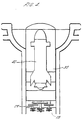
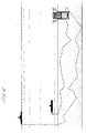
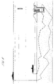
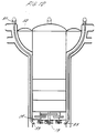
- An enclosure for installation in or on the seabed comprising an outer cylindrical container (10) having means to render one end of the container more buoyant than the other so that the container lies in a vertical orientation when disposed in the sea and means at the other end of the container for activating sand/silt/shingle on the seabed to create a cavity below the container into which the container can self-bury; characterised in that the container has a payload compartment within the container for holding weaponry, listening, identification recording and/or communications equipment; and in that the container wall is formed with a plurality of separate passages (A,B,C) extending spirally from inlets (16,17,18) at the lower end of the container upwardly to outlets (25,26,27) at the top of the container through which activated sand/silt/shingle and water generated at the lower end of the container can flow upwardly and freely as the container self-buries in the seabed.
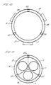
- An enclosure as claimed in claim 1, characterised in that the container has inner (14) and outer (13) concentric walls partitioned to form a plurality of spirally extending passageways (A,B,C) leading from inlets (16,17,18) at the lower end of the container to outlets (25,26,27) at the upper end of the container for delivery of sand/silt/shingle and water activated at the lower end of the container to the upper end of the container.
- An enclosure as claimed in claim 2, characterised in that said inlets are formed between the concentric walls of the inner side of the container at the lower end thereof.
- An enclosure as claimed in claim 2 or claim 3, characterised in that said outlets are formed in the outer periphery of the upper end of the container.
- An enclosure as claimed in any of the preceding claims, characterised in that the upper end of the container has a cup shaped head through which said passages (A,B,C) extend to outlets (25,26,27) at the outer periphery of the cup and a buoyancy chamber is formed within the cup to render the upper end of the container more buoyant than the lower end as aforesaid.
- An enclosure as claimed in any of the preceding claims, characterised in that a plurality of motor driven impellers/propellers (28) are mounted within the lower end of the container to act on the seabed below adjacent the respective inlet to the passages through the container wall.
- An enclosure as claimed in any of the preceding claims, characterised in that the thruster pumps are provided at spaced locations around the upper end of the container for maintaining the container upright as it self buries into the seabed and the inner container has gyro control equipment for controlling the thruster pumps.
- An enclosure as claimed in any of the preceding claims, characterised in that the inner container includes means to detect signals, vibration or noise transmitted through the seabed to activate the weaponry and/or communications equipment enclosed in the inner container.
- An enclosure as claimed in any of the preceding claims, characterised in that means are provided for pumping water from the upper end of the container to the lower end of the container to assist in maintaining the mixture of sand/silt released from the seabed in a fluid state to be drawn up through the container.
- An enclosure as claimed in claim 9, characterised in that said means for delivering water to the lower end of the container comprise conduits extending from the upper to lower ends of the container between the spirally extending passages for delivery of activated sand/silt and water from the lower end of the container to the upper end of the container, the pump means having discharge nozzles at the lower end of the container and said pump means connected to the upper end of the container.
- An enclosure as claimed in claim 10, characterised in that the inlets to the conduits at the upper end of the container are connected to a manifold encircling the upper end of the container and the pump is mounted in the upper end of the container for pumping water to the manifold for delivery by said conduits to the nozzles at the bottom end of the container.
Applications Claiming Priority (3)
| Application Number | Priority Date | Filing Date | Title |
|---|---|---|---|
| GBGB9516752.4A GB9516752D0 (en) | 1995-08-16 | 1995-08-16 | Improvements in or relating to seabed enclosures |
| GB9516752 | 1995-08-16 | ||
| PCT/GB1996/001945 WO1997007017A1 (en) | 1995-08-16 | 1996-08-09 | Improvements in or relating to seabed enclosures |
Publications (2)
| Publication Number | Publication Date |
|---|---|
| EP0844963A1 EP0844963A1 (en) | 1998-06-03 |
| EP0844963B1 true EP0844963B1 (en) | 2000-06-28 |
Family
ID=10779300
Family Applications (1)
| Application Number | Title | Priority Date | Filing Date |
|---|---|---|---|
| EP96927137A Expired - Lifetime EP0844963B1 (en) | 1995-08-16 | 1996-08-09 | Improvements in or relating to seabed enclosures |
Country Status (7)
| Country | Link |
|---|---|
| US (1) | US6044745A (en) |
| EP (1) | EP0844963B1 (en) |
| AT (1) | ATE194112T1 (en) |
| AU (1) | AU694058B2 (en) |
| DE (1) | DE69609072T2 (en) |
| GB (1) | GB9516752D0 (en) |
| WO (1) | WO1997007017A1 (en) |
Cited By (5)
| Publication number | Priority date | Publication date | Assignee | Title |
|---|---|---|---|---|
| EP1092937A2 (en) | 1999-10-13 | 2001-04-18 | Lawborough Consultants Limited | Enclosure for installation in the seabed |
| US6505452B1 (en) | 1999-06-30 | 2003-01-14 | Akzenta Paneele + Profile Gmbh | Panel and fastening system for panels |
| US7065935B2 (en) | 1999-07-02 | 2006-06-27 | Akzenta Paneele & Profile Gmbh | Method for laying and interlocking panels |
| US7451578B2 (en) | 2001-08-10 | 2008-11-18 | Akzenta Paneele + Profile Gmbh | Panel and fastening system for such a panel |
| US20140209003A1 (en) * | 2012-12-27 | 2014-07-31 | Japan System Planning Co., Ltd. | Sea-based buoyancy type torpedo storage and launch system, torpedo storage and launch apparatus, and buoyant rise type torpedo |
Families Citing this family (17)
| Publication number | Priority date | Publication date | Assignee | Title |
|---|---|---|---|---|
| US6951138B1 (en) * | 2000-11-01 | 2005-10-04 | Westerngeco L.L.C. | Method and apparatus for an ocean bottom seismic acquisition technique |
| GB2368560A (en) | 2000-11-02 | 2002-05-08 | Lawborough Consultants Ltd | Vessel and apparatus for clearing seabed mines |
| GB2377412A (en) | 2000-11-03 | 2003-01-15 | Lawborough Consultants Ltd | Support vessel for self-burying mines |
| US8293808B2 (en) | 2003-09-30 | 2012-10-23 | Cargill, Incorporated | Flexible polyurethane foams prepared using modified vegetable oil-based polyols |
| JP2008504287A (en) | 2004-06-25 | 2008-02-14 | ピッツバーグ ステート ユニバーシティ | Modified vegetable oil based polyols |
| US8161899B1 (en) * | 2008-09-11 | 2012-04-24 | The United States Of America As Represented By The Secretary Of The Navy | Multiple torpedo mine |
| GB201116285D0 (en) * | 2011-09-21 | 2011-11-02 | Go Science Ltd | Deployment of seabed device |
| US9383471B2 (en) * | 2012-09-14 | 2016-07-05 | Cgg Services Sa | Method and underwater node for seismic survey |
| US9381986B2 (en) | 2012-11-21 | 2016-07-05 | Seabed Geosolutions B.V. | Jet-pump-based autonomous underwater vehicle and method for coupling to ocean bottom during marine seismic survey |
| EP2929374A2 (en) * | 2012-12-10 | 2015-10-14 | CGG Services SA | Offshore seismic monitoring system and method |
| US9457879B2 (en) | 2012-12-17 | 2016-10-04 | Seabed Geosolutions B.V. | Self-burying autonomous underwater vehicle and method for marine seismic surveys |
| US9417351B2 (en) * | 2012-12-21 | 2016-08-16 | Cgg Services Sa | Marine seismic surveys using clusters of autonomous underwater vehicles |
| US20150003194A1 (en) * | 2013-06-26 | 2015-01-01 | Cgg Services Sa | Directional self-burying sensor system and method |
| CZ2014679A3 (en) * | 2014-10-06 | 2015-10-21 | Vysoká škola báňská- Technická univerzita Ostrava | Device to sense mechanical-physical and optical values of bulk materials |
| US10571222B2 (en) * | 2017-09-07 | 2020-02-25 | Stephen Tomás Strocchia-Rivera | Payload launching apparatus and method |
| CN110319733B (en) * | 2019-07-11 | 2020-06-19 | 北京航空航天大学 | Buried camouflage missile launching system |
| CN110319734B (en) * | 2019-07-11 | 2020-06-19 | 北京航空航天大学 | Underground camouflage small carrier rocket launching system |
Family Cites Families (8)
| Publication number | Priority date | Publication date | Assignee | Title |
|---|---|---|---|---|
| US3035285A (en) * | 1961-09-18 | 1962-05-22 | Jr Walter G Squires | Explosively anchored buoy |
| CH503847A (en) * | 1969-02-27 | 1971-02-28 | Mengis Geb | Trench pulling device and method of operating the same |
| DE2154231A1 (en) * | 1971-10-30 | 1973-05-03 | Erno Raumfahrttechnik Gmbh | DRILL ANCHOR ARRANGEMENT |
| GB2048439B (en) * | 1979-04-30 | 1982-12-15 | Lawborough Consultants Ltd | Underwater weapons |
| US4395952A (en) * | 1980-12-04 | 1983-08-02 | Hickey Christopher D D | Underwater weapon systems |
| DE3380273D1 (en) * | 1982-10-28 | 1989-08-31 | Underwater Storage Ltd | Underwater weapon systems |
| EP0116211A3 (en) * | 1982-12-10 | 1987-05-06 | Underwater Storage Limited | Underwater weapon systems |
| US5837919A (en) * | 1996-12-05 | 1998-11-17 | The United States Of America As Represented By The Secretary Of The Navy | Portable launcher |
-
1995
- 1995-08-16 GB GBGB9516752.4A patent/GB9516752D0/en active Pending
-
1996
- 1996-08-09 EP EP96927137A patent/EP0844963B1/en not_active Expired - Lifetime
- 1996-08-09 US US09/011,651 patent/US6044745A/en not_active Expired - Lifetime
- 1996-08-09 AU AU67068/96A patent/AU694058B2/en not_active Ceased
- 1996-08-09 WO PCT/GB1996/001945 patent/WO1997007017A1/en active IP Right Grant
- 1996-08-09 DE DE69609072T patent/DE69609072T2/en not_active Expired - Fee Related
- 1996-08-09 AT AT96927137T patent/ATE194112T1/en not_active IP Right Cessation
Cited By (9)
| Publication number | Priority date | Publication date | Assignee | Title |
|---|---|---|---|---|
| US6505452B1 (en) | 1999-06-30 | 2003-01-14 | Akzenta Paneele + Profile Gmbh | Panel and fastening system for panels |
| US7065935B2 (en) | 1999-07-02 | 2006-06-27 | Akzenta Paneele & Profile Gmbh | Method for laying and interlocking panels |
| US7856789B2 (en) * | 1999-07-02 | 2010-12-28 | Akzenta Paneele & Profile Gmbh | Method for laying and interlocking panels |
| EP1092937A2 (en) | 1999-10-13 | 2001-04-18 | Lawborough Consultants Limited | Enclosure for installation in the seabed |
| EP1092937A3 (en) * | 1999-10-13 | 2002-04-03 | Lawborough Consultants Limited | Enclosure for installation in the seabed |
| US6371003B1 (en) | 1999-10-13 | 2002-04-16 | Lawborough Consultants Limited | Enclosures for installation on the seabed |
| US7451578B2 (en) | 2001-08-10 | 2008-11-18 | Akzenta Paneele + Profile Gmbh | Panel and fastening system for such a panel |
| US20140209003A1 (en) * | 2012-12-27 | 2014-07-31 | Japan System Planning Co., Ltd. | Sea-based buoyancy type torpedo storage and launch system, torpedo storage and launch apparatus, and buoyant rise type torpedo |
| US9200879B2 (en) * | 2012-12-27 | 2015-12-01 | Japan System Planning Co., Ltd. | Sea-based buoyancy type torpedo storage and launch system, torpedo storage and launch apparatus, and buoyant rise type torpedo |
Also Published As
| Publication number | Publication date |
|---|---|
| WO1997007017A1 (en) | 1997-02-27 |
| DE69609072T2 (en) | 2001-03-22 |
| AU694058B2 (en) | 1998-07-09 |
| EP0844963A1 (en) | 1998-06-03 |
| DE69609072D1 (en) | 2000-08-03 |
| GB9516752D0 (en) | 1995-10-18 |
| ATE194112T1 (en) | 2000-07-15 |
| US6044745A (en) | 2000-04-04 |
| AU6706896A (en) | 1997-03-12 |
Similar Documents
| Publication | Publication Date | Title |
|---|---|---|
| EP0844963B1 (en) | Improvements in or relating to seabed enclosures | |
| US11267546B2 (en) | Ocean bottom seismic autonomous underwater vehicle | |
| US10099760B2 (en) | Deployment and retrieval of seismic autonomous underwater vehicles | |
| EP3156318B1 (en) | Seismic autonomous underwater vehicle | |
| US5577942A (en) | Station keeping buoy system | |
| CA2082165C (en) | Oil recovery system and apparatus | |
| US9381984B2 (en) | Apparatus for subsea transport of sensor systems | |
| US20150336645A1 (en) | Autonomous underwater vehicle marine seismic surveys | |
| AU2012296711B2 (en) | Communication buoy and method of deployment | |
| JPS58772B2 (en) | Deep-sea self-propelled unmanned submersible | |
| EP1588186B1 (en) | Sonar array system | |
| US4586421A (en) | Underwater weapon systems | |
| US20190353815A1 (en) | Cathedral body structure for an ocean bottom seismic node | |
| US7736094B1 (en) | Self-contained burying device for submerged environments | |
| EP1092937B1 (en) | Enclosure for installation in the seabed | |
| US6568341B1 (en) | Vessel for data collection in aquatic environments | |
| AU2021292366A1 (en) | Floating or submersible body for acoustic position finding, in particular for de-mining activities | |
| Dzielski et al. | NAVOCEANO Seahorse AUV design, testing, and capabilities | |
| CA2324084A1 (en) | Imaging system for detecting underground and underwater objects and associated method | |
| EP3204732B1 (en) | Device for sensing mechanical-physical and optical properties of bulk solids | |
| JP2021054378A (en) | Water bottom shape measuring device |
Legal Events
| Date | Code | Title | Description |
|---|---|---|---|
| PUAI | Public reference made under article 153(3) epc to a published international application that has entered the european phase |
Free format text: ORIGINAL CODE: 0009012 |
|
| 17P | Request for examination filed |
Effective date: 19980219 |
|
| AK | Designated contracting states |
Kind code of ref document: A1 Designated state(s): AT BE CH DE DK ES FI FR GB GR IE IT LI LU MC NL PT SE |
|
| 17Q | First examination report despatched |
Effective date: 19980618 |
|
| GRAG | Despatch of communication of intention to grant |
Free format text: ORIGINAL CODE: EPIDOS AGRA |
|
| RAP1 | Party data changed (applicant data changed or rights of an application transferred) |
Owner name: LAWBOROUGH CONSULTANTS LIMITED |
|
| GRAG | Despatch of communication of intention to grant |
Free format text: ORIGINAL CODE: EPIDOS AGRA |
|
| GRAH | Despatch of communication of intention to grant a patent |
Free format text: ORIGINAL CODE: EPIDOS IGRA |
|
| GRAH | Despatch of communication of intention to grant a patent |
Free format text: ORIGINAL CODE: EPIDOS IGRA |
|
| ITF | It: translation for a ep patent filed |
Owner name: BARZANO' E ZANARDO ROMA S.P.A. |
|
| GRAA | (expected) grant |
Free format text: ORIGINAL CODE: 0009210 |
|
| AK | Designated contracting states |
Kind code of ref document: B1 Designated state(s): AT BE CH DE DK ES FI FR GB GR IE IT LI LU MC NL PT SE |
|
| PG25 | Lapsed in a contracting state [announced via postgrant information from national office to epo] |
Ref country code: NL Free format text: LAPSE BECAUSE OF FAILURE TO SUBMIT A TRANSLATION OF THE DESCRIPTION OR TO PAY THE FEE WITHIN THE PRESCRIBED TIME-LIMIT Effective date: 20000628 Ref country code: LI Free format text: LAPSE BECAUSE OF FAILURE TO SUBMIT A TRANSLATION OF THE DESCRIPTION OR TO PAY THE FEE WITHIN THE PRESCRIBED TIME-LIMIT Effective date: 20000628 Ref country code: GR Free format text: LAPSE BECAUSE OF NON-PAYMENT OF DUE FEES Effective date: 20000628 Ref country code: FI Free format text: LAPSE BECAUSE OF FAILURE TO SUBMIT A TRANSLATION OF THE DESCRIPTION OR TO PAY THE FEE WITHIN THE PRESCRIBED TIME-LIMIT Effective date: 20000628 Ref country code: ES Free format text: THE PATENT HAS BEEN ANNULLED BY A DECISION OF A NATIONAL AUTHORITY Effective date: 20000628 Ref country code: CH Free format text: LAPSE BECAUSE OF FAILURE TO SUBMIT A TRANSLATION OF THE DESCRIPTION OR TO PAY THE FEE WITHIN THE PRESCRIBED TIME-LIMIT Effective date: 20000628 Ref country code: BE Free format text: LAPSE BECAUSE OF FAILURE TO SUBMIT A TRANSLATION OF THE DESCRIPTION OR TO PAY THE FEE WITHIN THE PRESCRIBED TIME-LIMIT Effective date: 20000628 Ref country code: AT Free format text: LAPSE BECAUSE OF FAILURE TO SUBMIT A TRANSLATION OF THE DESCRIPTION OR TO PAY THE FEE WITHIN THE PRESCRIBED TIME-LIMIT Effective date: 20000628 |
|
| REF | Corresponds to: |
Ref document number: 194112 Country of ref document: AT Date of ref document: 20000715 Kind code of ref document: T |
|
| REG | Reference to a national code |
Ref country code: CH Ref legal event code: EP |
|
| REG | Reference to a national code |
Ref country code: IE Ref legal event code: FG4D |
|
| REF | Corresponds to: |
Ref document number: 69609072 Country of ref document: DE Date of ref document: 20000803 |
|
| ET | Fr: translation filed | ||
| PG25 | Lapsed in a contracting state [announced via postgrant information from national office to epo] |
Ref country code: LU Free format text: LAPSE BECAUSE OF NON-PAYMENT OF DUE FEES Effective date: 20000809 Ref country code: IE Free format text: LAPSE BECAUSE OF NON-PAYMENT OF DUE FEES Effective date: 20000809 |
|
| PG25 | Lapsed in a contracting state [announced via postgrant information from national office to epo] |
Ref country code: MC Free format text: THE PATENT HAS BEEN ANNULLED BY A DECISION OF A NATIONAL AUTHORITY Effective date: 20000831 |
|
| PG25 | Lapsed in a contracting state [announced via postgrant information from national office to epo] |
Ref country code: SE Free format text: LAPSE BECAUSE OF FAILURE TO SUBMIT A TRANSLATION OF THE DESCRIPTION OR TO PAY THE FEE WITHIN THE PRESCRIBED TIME-LIMIT Effective date: 20000928 Ref country code: PT Free format text: LAPSE BECAUSE OF FAILURE TO SUBMIT A TRANSLATION OF THE DESCRIPTION OR TO PAY THE FEE WITHIN THE PRESCRIBED TIME-LIMIT Effective date: 20000928 Ref country code: DK Free format text: LAPSE BECAUSE OF FAILURE TO SUBMIT A TRANSLATION OF THE DESCRIPTION OR TO PAY THE FEE WITHIN THE PRESCRIBED TIME-LIMIT Effective date: 20000928 |
|
| NLV1 | Nl: lapsed or annulled due to failure to fulfill the requirements of art. 29p and 29m of the patents act | ||
| REG | Reference to a national code |
Ref country code: CH Ref legal event code: PL |
|
| PLBE | No opposition filed within time limit |
Free format text: ORIGINAL CODE: 0009261 |
|
| STAA | Information on the status of an ep patent application or granted ep patent |
Free format text: STATUS: NO OPPOSITION FILED WITHIN TIME LIMIT |
|
| REG | Reference to a national code |
Ref country code: IE Ref legal event code: MM4A |
|
| 26N | No opposition filed | ||
| REG | Reference to a national code |
Ref country code: GB Ref legal event code: IF02 |
|
| GBPC | Gb: european patent ceased through non-payment of renewal fee |
Effective date: 20050809 |
|
| PGFP | Annual fee paid to national office [announced via postgrant information from national office to epo] |
Ref country code: FR Payment date: 20060718 Year of fee payment: 11 |
|
| PGFP | Annual fee paid to national office [announced via postgrant information from national office to epo] |
Ref country code: IT Payment date: 20060831 Year of fee payment: 11 |
|
| REG | Reference to a national code |
Ref country code: GB Ref legal event code: 728V |
|
| PGFP | Annual fee paid to national office [announced via postgrant information from national office to epo] |
Ref country code: DE Payment date: 20061030 Year of fee payment: 11 |
|
| REG | Reference to a national code |
Ref country code: GB Ref legal event code: 728Y |
|
| REG | Reference to a national code |
Ref country code: FR Ref legal event code: ST Effective date: 20080430 |
|
| PG25 | Lapsed in a contracting state [announced via postgrant information from national office to epo] |
Ref country code: DE Free format text: LAPSE BECAUSE OF NON-PAYMENT OF DUE FEES Effective date: 20080301 |
|
| PG25 | Lapsed in a contracting state [announced via postgrant information from national office to epo] |
Ref country code: FR Free format text: LAPSE BECAUSE OF NON-PAYMENT OF DUE FEES Effective date: 20070831 |
|
| PG25 | Lapsed in a contracting state [announced via postgrant information from national office to epo] |
Ref country code: IT Free format text: LAPSE BECAUSE OF NON-PAYMENT OF DUE FEES Effective date: 20070809 |
|
| PGFP | Annual fee paid to national office [announced via postgrant information from national office to epo] |
Ref country code: GB Payment date: 20110825 Year of fee payment: 16 |
|
| GBPC | Gb: european patent ceased through non-payment of renewal fee |
Effective date: 20120809 |
|
| PG25 | Lapsed in a contracting state [announced via postgrant information from national office to epo] |
Ref country code: GB Free format text: LAPSE BECAUSE OF NON-PAYMENT OF DUE FEES Effective date: 20120809 |