EP0845238A2 - Device for endoscopic diagnostics and for treatment of tissue - Google Patents
Device for endoscopic diagnostics and for treatment of tissue Download PDFInfo
- Publication number
- EP0845238A2 EP0845238A2 EP97119015A EP97119015A EP0845238A2 EP 0845238 A2 EP0845238 A2 EP 0845238A2 EP 97119015 A EP97119015 A EP 97119015A EP 97119015 A EP97119015 A EP 97119015A EP 0845238 A2 EP0845238 A2 EP 0845238A2
- Authority
- EP
- European Patent Office
- Prior art keywords
- diagnostic
- distal end
- laser
- light
- lasers
- Prior art date
- Legal status (The legal status is an assumption and is not a legal conclusion. Google has not performed a legal analysis and makes no representation as to the accuracy of the status listed.)
- Granted
Links
Images


Classifications
-
- A—HUMAN NECESSITIES
- A61—MEDICAL OR VETERINARY SCIENCE; HYGIENE
- A61B—DIAGNOSIS; SURGERY; IDENTIFICATION
- A61B1/00—Instruments for performing medical examinations of the interior of cavities or tubes of the body by visual or photographical inspection, e.g. endoscopes; Illuminating arrangements therefor
- A61B1/00064—Constructional details of the endoscope body
- A61B1/00071—Insertion part of the endoscope body
- A61B1/0008—Insertion part of the endoscope body characterised by distal tip features
- A61B1/00096—Optical elements
-
- A—HUMAN NECESSITIES
- A61—MEDICAL OR VETERINARY SCIENCE; HYGIENE
- A61B—DIAGNOSIS; SURGERY; IDENTIFICATION
- A61B1/00—Instruments for performing medical examinations of the interior of cavities or tubes of the body by visual or photographical inspection, e.g. endoscopes; Illuminating arrangements therefor
- A61B1/00163—Optical arrangements
- A61B1/00174—Optical arrangements characterised by the viewing angles
- A61B1/00179—Optical arrangements characterised by the viewing angles for off-axis viewing
-
- A—HUMAN NECESSITIES
- A61—MEDICAL OR VETERINARY SCIENCE; HYGIENE
- A61B—DIAGNOSIS; SURGERY; IDENTIFICATION
- A61B1/00—Instruments for performing medical examinations of the interior of cavities or tubes of the body by visual or photographical inspection, e.g. endoscopes; Illuminating arrangements therefor
- A61B1/06—Instruments for performing medical examinations of the interior of cavities or tubes of the body by visual or photographical inspection, e.g. endoscopes; Illuminating arrangements therefor with illuminating arrangements
- A61B1/063—Instruments for performing medical examinations of the interior of cavities or tubes of the body by visual or photographical inspection, e.g. endoscopes; Illuminating arrangements therefor with illuminating arrangements for monochromatic or narrow-band illumination
-
- A—HUMAN NECESSITIES
- A61—MEDICAL OR VETERINARY SCIENCE; HYGIENE
- A61B—DIAGNOSIS; SURGERY; IDENTIFICATION
- A61B1/00—Instruments for performing medical examinations of the interior of cavities or tubes of the body by visual or photographical inspection, e.g. endoscopes; Illuminating arrangements therefor
- A61B1/06—Instruments for performing medical examinations of the interior of cavities or tubes of the body by visual or photographical inspection, e.g. endoscopes; Illuminating arrangements therefor with illuminating arrangements
- A61B1/0638—Instruments for performing medical examinations of the interior of cavities or tubes of the body by visual or photographical inspection, e.g. endoscopes; Illuminating arrangements therefor with illuminating arrangements providing two or more wavelengths
-
- A—HUMAN NECESSITIES
- A61—MEDICAL OR VETERINARY SCIENCE; HYGIENE
- A61B—DIAGNOSIS; SURGERY; IDENTIFICATION
- A61B5/00—Measuring for diagnostic purposes; Identification of persons
- A61B5/0059—Measuring for diagnostic purposes; Identification of persons using light, e.g. diagnosis by transillumination, diascopy, fluorescence
- A61B5/0082—Measuring for diagnostic purposes; Identification of persons using light, e.g. diagnosis by transillumination, diascopy, fluorescence adapted for particular medical purposes
- A61B5/0084—Measuring for diagnostic purposes; Identification of persons using light, e.g. diagnosis by transillumination, diascopy, fluorescence adapted for particular medical purposes for introduction into the body, e.g. by catheters
-
- A—HUMAN NECESSITIES
- A61—MEDICAL OR VETERINARY SCIENCE; HYGIENE
- A61N—ELECTROTHERAPY; MAGNETOTHERAPY; RADIATION THERAPY; ULTRASOUND THERAPY
- A61N5/00—Radiation therapy
- A61N5/06—Radiation therapy using light
- A61N5/0601—Apparatus for use inside the body
Definitions
- the invention relates to a device for endoscopic diagnosis and treatment of tissue according to that specified in the preamble of claim 1 Characteristics.
- Endoscopic devices of the type mentioned in the introduction - such a device is known for example from US Pat. No. 5,413,108 - nowadays used for example in rectoscopy.
- This will make a leaner distal End section of a generally flexible endoscope over a body opening in the body in and up to the area to be diagnosed or treated led there.
- the tissue area to be diagnosed for example the intestinal wall, with at least two diagnostic lasers of different wavelengths irradiated, after which the remitted light - be it by reflection or by Fluorescence - wavelength dependent is detected.
- the receive signals are linked with each other depending on the image point by subtraction or quotient formation, whereby the topology of the tissue section to be diagnosed is switched off becomes.
- the device structure of this known from US Pat. No. 5,413,108 The arrangement is such that both the diagnostic and treatment lasers as well the receiving devices are located outside the endoscope and via light guides are connected to the distal endoscope end.
- the wavelength separation takes place via filters which are located in a disk which engages in the beam path, which can be driven by a motor.
- a disadvantage of the aforementioned devices is, in particular, the complicated one and technically complex construction. That emitted by reflection or fluorescence Light is extremely weak and must therefore be technically complex be strengthened before it can be received and evaluated. This leads to ultimately, that the diagnostic device has a comparatively low sensitivity has or does not work with the necessary reliability.
- Diagnosis and therapy often have problems with accuracy the place of diagnosis or therapy.
- the invention is based on the object to design a generic device so that on the one hand a high Accuracy or sensitivity, but on the other hand, an inexpensive and robust construction is achieved.
- the invention provides for the receiving device or in use several receiving devices these in the distal end section of the endoscopic To arrange part of the device. This can be done by fluorescence or reflection emitted light in the shortest way and avoiding elaborate optical devices are fed to the receiving devices, so that the otherwise usual complex amplifiers can be dispensed with.
- the Light guidance within the distal end section from the light entry to the Receiving device can usually only be done via mirrors, so that a large part of this light of the receiving device or the receiving devices can be supplied. It is particularly important that the Use of the usual light guides in the area between light entry and Receiving device can be completely dispensed with, which otherwise Usual small acceptance angles are significantly increased and thus the coupling losses can be reduced considerably.
- the device according to the invention already shows a significantly higher sensitivity due to the design on as known from the prior art, the structure already thereby considerably cheaper and simpler that the usual Light amplifier can be completely dispensed with.
- the accuracy with regard to the diagnosis and therapy site can according to the Invention can be further increased in that the beam paths of the emitted and incident light at the distal end of the device, d. H. the ray paths also matched by diagnostic and treatment lasers will.
- the merging of the beam paths is also constructive Advantages and enables a slim design of the device especially in the distal end area.
- the device according to the invention can be equipped with a diagnostic laser and a receiving device can be operated if both the diagnostic laser as well as the receiving device are used so clocked that for a specific time interval generates and receives light of a first wavelength and generates light of a second wavelength for a further time interval and is received, as described, for example, in US Pat. No. 5,413,108. In extreme cases, however, this can lead to motion blur, which is why According to the invention it is preferably proposed to have at least two diagnostic lasers to provide different wavelengths and each diagnostic laser in Assign distal end portion of the device arranged receiving device. Then both diagnostic lasers can be operated simultaneously, accordingly the reception takes place, so that the electronic signal linkage an almost real-time image is always created for topology elimination.
- the evaluation is based on very different absorption / remission of the two diagnostic wavelength ranges advantageous.
- the topology of the irradiated tissue area Irradiation with two different wavelengths and a corresponding one Evaluation.
- three Diagnostic lasers of different wavelengths are provided, which are preferred cover the wavelength ranges red, green and blue. Then namely with the received signals received from the reflected light in these three wavelength ranges additionally a natural color image, for example on a monitor being represented.
- the attending physician can thus do the arithmetic Subtraction, quotient formation or other suitably formed diagnostic image also his experiences from the natural picture bring in.
- the device advantageously has inside the distal end section on scanning devices, which the laser beams of Deflect the diagnostic laser horizontally and vertically before hitting it.
- the respective Distraction is recorded electronically so that the diagnostic field is time-dependent certain diagnostic points can be assigned. Accordingly, the Signals of the receiving devices linked, so that an imaging dot matrix arises through frequent polling, for example three times per second, can be fed as an image to a monitor, for example regardless of the polling frequency be clocked at 50 or 100 Hz to obtain a calm image can.
- microscanners are known per se. It will be in this context on “microsystem technology 1994 to 1999, program within the framework of the future concept Information Technology ", published by the Federal Ministry for Research and Technology - Public Relations from January 1994 (ISBN 3-88135-276-7), referenced there, in particular on page 81.
- These mirrors will be Usually operated in the resonance range, so that the evaluation electronics only is to be adapted to the resonance frequency.
- it is also possible these mirrors through targeted electromagnetic exposure of the selectively move one or the other side to achieve the desired scan effect achieve, d. H. the point of impact of a diagnostic laser beam in the diagnostic field to influence specifically.
- each receiving device has a photodiode is assigned, the wavelength-dependent division of the remitted Light in a manner known per se via semipermeable, dicroitic coated prisms or prism arrangements can take place. That is advantageous Evaluation of the received signals with the release or trigger control of the Treatment laser linked so that, for example, a triggering of the treatment laser is only possible if a given (malignant tissue characteristic) threshold within the treatment laser Image area is exceeded. On the other hand, an active intervention in the Control of the treatment laser in such a way that an automatic triggering when a predetermined threshold value is exceeded.
- This autofocus device can take advantage of existing components in the distal end section be integrated, even if their beam path with that of the diagnostic laser and that of the treatment laser coincides in the distal end of the device.
- the focusing lens of the autofocus device is preferably in the distal end section arranged directly in front of the distal end window and by, for example, a conventional magnet coil arrangement by electromagnetic Actuation in the axial direction of the beam path for the purpose of focusing relocatable.
- the autofocus device preferably works with the most intensely remitted Wavelength range (lowest absorption e.g. 1.3 ⁇ m in the infrared range and 0.35 ⁇ m in the UV range), using the corresponding diagnostic laser emitted light can be used if an appropriate timing between the reception required for the autofocus device and the necessary reception for the diagnosis takes place.
- the Photodiodes of the receiving devices also form part of the autofocus device. This not only leads to cost-effective and space-saving training of the endoscopic end section, but also to a particularly high accuracy the autofocus device and thus a high accuracy of the whole Contraption.
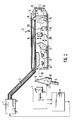
- the device according to FIG. 2 has a treatment laser 1. It deals is a 1.06 ⁇ m Nd-YAG laser.
- the light of the treatment laser 1 is passed over a multimode fiber bundle 2, which in a distal end section 3 of a and not shown here in detail described endoscopic instrument, for example a flexible Endoscope similar to that known from US Pat. No. 5,413,108 opens.
- a multimode fiber bundle 2 which in a distal end section 3 of a and not shown here in detail described endoscopic instrument, for example a flexible Endoscope similar to that known from US Pat. No. 5,413,108 opens.
- an electronic evaluation and Control unit 4 and two diagnostic lasers 5 and 6 arranged.
- Any diagnostic laser is via a beam splitter block 8 made up of two prisms with a receiving device for remitted light connected in the form of a photodiode 7.
- the Diagnostic lasers 5 and 6 with their associated photodiodes 7 are in turn a common partially mirrored prism 9 in the same beam path of a single-mode fiber 10 coupled, which also opens into the distal end section 3.
- the Diagnostic lasers 5 and 6 work in one in this embodiment Wavelength range of 1.31 ⁇ m or 1.55 ⁇ m, which is one to order of magnitude Factor 10 different absorption and thus have remission in the tissue. Similar differences can be achieved in the UV range (0.2 ⁇ m and 0.35 ⁇ m wavelength).
- the lasers 5,6 are designed as laser diodes, wherein the laser 5 operating in the 1.31 ⁇ m range essentially for topology detection of the tissue area to be examined, while in the 1.55 ⁇ m area working laser 6 for the detection of topology and tissue-specific Considerations.
- Laser beams of the diagnostic lasers 5 and 6 are within the end section 3 a suitable vertical mirror scanner 12 and subsequently fed to a horizontal scanner 11.
- the scanners 11, 12 It is silicon two-axis scanner, which is due to electromagnetic Excitation at a given frequency and swing one axis.
- the Axes of the scanners 11 and 12 are arranged so that the monomode fiber 10 coming light beams in two planes offset by 90 ° to each other get distracted. Due to this deflection, the punctiform rays of light directed to an essentially square field.
- each a beam splitter block 14 fed to then in a further distal prism block 15 to be reunited.
- Via a prism block behind it 16 then becomes the beam path of the diagnostic laser 5, 6 in this beam path of the treatment laser 1 coupled.
- This common beam path 17 passes through a lens 18 of an autofocus device before passing over the distal side Window 19 exits the distal end portion 3 of the device.
- the lens 18 is via a magnetic coil arrangement, as is usual with autofocus devices, in Axial direction of the beam path 17 movable.
- the autofocus device works in time windows, in which the diagnosis and therapy function is interrupted, taking advantage of of the light reflected by the diagnostic lasers 5 and 6 on the object. By moving the lens 18 becomes the intensity maximum with the help of the photodiodes 20 of the remitted light and thus the optimally focusing position of the lens 18 determined.
- the one generated by the diagnostic lasers 5, 6 arrives and light remitted by the object through the beam splitter blocks over which Prism block 13 to the scanners 11, 12, which it via the prism 9 back to the Throw beam splitter blocks 8 where there is intensity by means of the photodiodes 7 is detected.
- the signal of the photodiodes 7 is the electrical evaluation and Control unit 4 supplied in which a pixel assignment corresponding to the current scanner position in the diagnostic field and thus the structure of one Pixels existing matrix takes place, depending on the wavelength, for one for the light remitted by the diagnostic laser 5 and the other for the light Diagnostic laser 6 remitted light.
- the signal processing within the control unit 4 is based on that in FIG. 1 illustrated block diagram illustrates.
- the signal of the photodiodes 7 is first fed to an analog-to-digital converter 21.
- the digital The output signal of this analog-digital converter in turn becomes a central one Image processing unit 22 fed.
- this image processing unit 22 the data from the photodiodes 7 digitized data using the synchronization data Scanners 11 and 12 on the one hand, depending on the wavelength, from individual pixels constructed image matrices processed, which, insofar as they are from the reflected light of the Diagnostic laser 5 originate, an image memory A and, insofar as they are from the remitted Light from the diagnostic laser 6 originate, are fed to an image memory B.
- the wavelength-dependent in the central image processing unit 22 Computationally linked image data, optionally by subtraction or by forming quotients.
- the arithmetically determined image becomes one Image memory C supplied. While image memories A and B are essentially for the access of the central image processing unit to determine the values for the Serve image memories C and can only be displayed optionally on a monitor 23, the image memory C is at regular intervals, for example three times a Second, queried by an analysis unit 24 while the looped through Signal processed in a video unit 25 and displayed on the monitor 23 becomes.
- the computationally linked image of the image memory is thus displayed on the monitor 23 C, which is topology-adjusted, i.e. only shows an image that especially recognize the contours between malignant and healthy tissue leaves. By switching on pictures A and B, if desired, the topology can also be displayed alone or in addition.
- An electronic evaluation of the image takes place within the analysis unit 24 C, in particular in the central area that is currently being treated by the treatment laser 1 is covered.
- a signal is output to the controller 26 of the treatment laser 1.
- the control unit 4 can be switched in such a way that the controller 26 when it comes on Signal of the analysis unit 24 automatically switches on the treatment laser 1 or a release of a manual control of the treatment laser 1 which is controlled by the attending doctor. This way it can be reliable be prevented that the treatment laser 1 accidentally to Example is triggered when only healthy tissue has been diagnosed is. Only at a minimum content specified by setting the threshold Malignant tissue in the diagnostic window can trigger the treatment laser take place or this takes place automatically.
- the monitor is always displayed with a repetition frequency of 50 or more Hz, but the query frequency of the image memory is significantly lower can be, for example, three times per second. In this way, the Image processing unit enough time to receive the pixel data coming at different times to compile an overall picture and process it mathematically. in the The display of the monitor is left by the time window for the autofocus not affected, although the treatment laser is locked during this time.
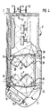
- the embodiment shown in FIG. 3 differs from the one described above characterized in that the beams of the diagnostic lasers 5 and 6 via separate Monomode fibers are guided up to the distal end section 3 ', where they over a suitable prism arrangement 27 are brought together. From there they will again a vertical and then a horizontal scanner 12 or 11 fed. From there, the prism is arranged again a wavelength-dependent beam splitting. In beam splitter blocks 28 The intensity of the light emitted by the diagnostic lasers 5 and 6 via photodiodes 29 Light measured. By recording the radiating diagnostic power In the control unit 4, intensity fluctuations of the diagnostic lasers 5 and 6 can be compensated, thereby excluding another possible source of errors becomes.
- the beams then arrive via further beam splitter blocks 30 a prism arrangement 31 in which the beams of both diagnostic lasers 5 and 6 reunited and with the beam path of the treatment laser 1, which also is connected to the distal end section 3 'via a multimode fiber bundle 2, coupled.
- the common beam path of diagnostic lasers 5, 6 and treatment lasers 1 then leads through the in this embodiment to the longitudinal axis of the distal End portion 3 'inclined lens 18 to the also inclined distal window 19.
- the lens 18 is part of an autofocus device, provided with a coil arrangement on its outer circumference and slidably arranged in the axial direction.
- the one with the coil arrangement interacting permanent ring magnet is with reference numeral 32 in Figure 3 featured.
- the photodiodes 7 are for detection the intensity of the remitted light in the embodiment according to FIG. 3 arranged within the distal end portion 3 ', at the bottom of the Beam splitter blocks 30. Since here the intensity measurement before passing the Scanner 11 and 12 takes place, the measurement is much easier, because the the intensity of the reflected light is significantly higher and others through the measurement over the whole area a significantly larger amount of light Measurement is available. In this respect, this arrangement is compared to to be preferred based on Figure 2.
- angles ⁇ and ⁇ correspond to those of the embodiment according to FIG. 3.
- the main difference from the previously described embodiment is that three diagnostic lasers, 5, 6 and 33 are provided.
- the wavelengths of these three Diagnostic lasers are selected so that a laser in the red area, a laser in the green area and one works in the blue area so that the rays become natural add white light.
- the prism arrangements are modified accordingly, and there are three photodiodes 29 for detecting power fluctuations in the Diagnostic laser and three photodiodes 7 for wavelength-dependent intensity determination intended.
- the control unit 4 is adapted accordingly, in addition to a further analog-digital converter 21 also a further image memory is provided. so that by querying three image memories on the monitor 23rd a natural color image can optionally be displayed for the arithmetically linked image is. This has the particular advantage that the treating doctor is independent from the calculated diagnosis result also a natural picture of the diagnosing tissue site, i.e. the one irradiated by the diagnostic lasers Diagnostic field can make.
Abstract
Description
Die Erfindung betrifft eine Vorrichtung zur endoskopischen Diagnose und Behandlung von Gewebe gemäß den im Oberbegriff des Anspruchs 1 angegebenen Merkmalen.The invention relates to a device for endoscopic diagnosis and treatment of tissue according to that specified in the preamble of claim 1 Characteristics.
Endoskopische Vorrichtungen der eingangs erwähnten Art - eine solche Vorrichtung ist beispielsweise aus US-PS 5,413,108 bekannt - werden heutzutage beispielsweise in der Rektoskopie angewendet. Dabei wird ein schlanker distaler Endabschnitt eines in der Regel flexiblen Endoskopes über eine Körperöffnung in den Körper ein- und bis zur zu diagnostizierenden bzw. zu behandelnden Stelle hingeführt. Der zu diagnostizierende Gewebebereich, beispielsweise die Darmwand, wird mit mindestens zwei Diagnoselasern unterschiedlicher Wellenlänge bestrahlt, wonach das remittierte Licht - sei es durch Reflexion oder auch durch Fluoreszenz - wellenlängenabhängig erfaßt wird. Die Empfangssignale werden bildpunktabhängig durch Subtraktion oder Quotientenbildung miteinander verknüpft, wodurch die Topologie des zu diagnostizierenden Gewebeabschnitts ausgeschaltet wird. Es werden also durch diese elektronischen Signalverknüpfungen Intensitätsunterschiede des empfangenen Bildes, wie sie beispielsweise durch Schatten, Erhöhungen, Vertiefungen und dergleichen entstehen, ausgeschaltet. Das verbleibende Bild bzw. elektrische Signal ermöglicht aufgrund der wellenlängenabhängigen Remissionserscheinungen von gesundem und malignem Gewebe die erwünschte Diagnose. Nach erfolgter Diagnose kann das maligne Gewebe direkt durch einen Behandlungslaser verdampft, also entfernt werden. Mittels der Diagnoselaser kann unmittelbar danach eine Kontrolle erfolgen, ob das maligne Gewebe vollständig entfernt worden ist oder nicht.Endoscopic devices of the type mentioned in the introduction - such a device is known for example from US Pat. No. 5,413,108 - nowadays used for example in rectoscopy. This will make a leaner distal End section of a generally flexible endoscope over a body opening in the body in and up to the area to be diagnosed or treated led there. The tissue area to be diagnosed, for example the intestinal wall, with at least two diagnostic lasers of different wavelengths irradiated, after which the remitted light - be it by reflection or by Fluorescence - wavelength dependent is detected. The receive signals are linked with each other depending on the image point by subtraction or quotient formation, whereby the topology of the tissue section to be diagnosed is switched off becomes. So it is through these electronic signal links Differences in intensity of the received image, such as by Shadows, elevations, depressions and the like arise, switched off. The remaining image or electrical signal enables due to the wavelength dependent Remission symptoms of healthy and malignant tissue die desired diagnosis. After diagnosis, the malignant tissue can be taken directly evaporated by a treatment laser, that is, removed. By means of the Diagnostic laser can be checked immediately after that whether the malignant Tissue has been completely removed or not.
Der vorrichtungsmäßige Aufbau dieser aus der US-PS 5,413,108 bekannten Anordnung ist so, daß sowohl die Diagnose- als auch die Behandlungslaser sowie die Empfangseinrichtungen außerhalb des Endoskopes liegen und über Lichtleiter mit dem distalen Endoskopende verbunden sind. Die Wellenlängenseparation erfolgt über Filter, die in einer in den Strahlengang eingreifenden Scheibe liegen, welche motorisch antreibbar ist.The device structure of this known from US Pat. No. 5,413,108 The arrangement is such that both the diagnostic and treatment lasers as well the receiving devices are located outside the endoscope and via light guides are connected to the distal endoscope end. The wavelength separation takes place via filters which are located in a disk which engages in the beam path, which can be driven by a motor.
Eine ähnliche Anordnung ist aus GB 2125986 A bekannt. Bei dieser Vorrichtung ist der Behandlungslaser nicht durch einen gesonderten Arbeitskanal hindurchzuführen, sondern bereits integriert.A similar arrangement is known from GB 2125986 A. With this device the treatment laser must not be passed through a separate working channel, but already integrated.
Nachteilig bei den vorerwähnten Vorrichtungen ist insbesondere der komplizierte und technisch aufwendige Aufbau. Das durch Reflexion oder Fluoreszenz emittierte Licht ist äußerst schwach und muß daher in technisch aufwendiger Weise verstärkt werden, bevor es empfangen und ausgewertet werden kann. Dies führt letztlich dazu, daß die Diagnoseeinrichtung eine vergleichsweise geringe Empfindlichkeit aufweist oder aber nicht mit der notwendigen Zuverlässigkeit arbeitet. Darüber hinaus ergeben sich bei den vorbekannten Vorrichtungen sowohl bei der Diagnose als auch bei der Therapie häufig Probleme hinsichtlich der Genauigkeit des Diagnose- bzw. Therapieortes.A disadvantage of the aforementioned devices is, in particular, the complicated one and technically complex construction. That emitted by reflection or fluorescence Light is extremely weak and must therefore be technically complex be strengthened before it can be received and evaluated. this leads to ultimately, that the diagnostic device has a comparatively low sensitivity has or does not work with the necessary reliability. In addition, both in the prior art devices Diagnosis and therapy often have problems with accuracy the place of diagnosis or therapy.
Ausgehend von diesem Stand der Technik liegt der Erfindung die Aufgabe zugrunde, eine gattungsgemäße Vorrichtung so auszubilden, daß einerseits eine hohe Genauigkeit bzw. Empfindlichkeit, jedoch andererseits ein kostengünstiger und robuster Aufbau erreicht wird. Starting from this prior art, the invention is based on the object to design a generic device so that on the one hand a high Accuracy or sensitivity, but on the other hand, an inexpensive and robust construction is achieved.
Diese Aufgabe wird gemäß der Erfindung durch die im kennzeichnenden Teil des Anspruches 1 angegebenen Merkmale gelöst.This object is achieved according to the invention by the in the characterizing part of Features specified claim 1 solved.
Demgemäß sieht die Erfindung vor, die Empfangseinrichtung bzw. beim Einsatz mehrerer Empfangseinrichtungen diese im distalen Endabschnitt des endoskopisehen Teils der Vorrichtung anzuordnen. Hierdurch kann das durch Fluoreszenz oder Reflexion emittierte Licht auf kürzestem Weg und unter Vermeidung aufwendiger optischer Vorrichtungen den Empfangsvorrichtungen zugeführt werden, so daß auf die sonst üblichen aufwendigen Verstärker verzichtet werden kann. Die Lichtführung innerhalb des distalen Endabschnittes vom Lichteintritt bis zur Empfangseinrichtung kann in der Regel ausschließlich über Spiegel erfolgen, so daß ein Großteil dieses Lichtes der Empfangseinrichtung bzw. den Empfangseinrichtungen zugeführt werden kann. Dabei ist insbesondere wesentlich, daß auf den Einsatz von den sonst üblichen Lichtleitern im Bereich zwischen Lichteintritt und Empfangseinrichtung vollständig verzichtet werden kann, wodurch der sonst übliche kleine Akzeptanzwinkel wesentlich vergrößert und damit die Einkoppelverluste ganz erheblich verringert werden können. Die erfindungsgemäße Vorrichtung weist damit schon konstruktionsbedingt eine wesentlich höhere Empfindlichkeit auf als die aus dem Stand der Technik bekannten, wobei der Aufbau schon dadurch erheblich kostengünstiger und einfacher ist, daß auf die sonst üblichen Lichtverstärker vollständig verzichtet werden kann.Accordingly, the invention provides for the receiving device or in use several receiving devices these in the distal end section of the endoscopic To arrange part of the device. This can be done by fluorescence or reflection emitted light in the shortest way and avoiding elaborate optical devices are fed to the receiving devices, so that the otherwise usual complex amplifiers can be dispensed with. The Light guidance within the distal end section from the light entry to the Receiving device can usually only be done via mirrors, so that a large part of this light of the receiving device or the receiving devices can be supplied. It is particularly important that the Use of the usual light guides in the area between light entry and Receiving device can be completely dispensed with, which otherwise Usual small acceptance angles are significantly increased and thus the coupling losses can be reduced considerably. The device according to the invention already shows a significantly higher sensitivity due to the design on as known from the prior art, the structure already thereby considerably cheaper and simpler that the usual Light amplifier can be completely dispensed with.
Die Genauigkeit hinsichtlich des Diagnose- und Therapieortes kann gemäß der Erfindung weiterhin dadurch erhöht werden, daß die Strahlengänge des ausgesandten und einfallenden Lichtes am distalen Ende der Vorrichtung, d. h. die Strahlengänge auch von Diagnose- und Behandlungslaser in Übereinstimmung gebracht werden. Das Zusammenführen der Strahlengänge hat darüber hinaus auch konstruktive Vorteile und ermöglicht eine schlanke Ausgestaltung der Vorrichtung insbesondere im distalen Endbereich. The accuracy with regard to the diagnosis and therapy site can according to the Invention can be further increased in that the beam paths of the emitted and incident light at the distal end of the device, d. H. the ray paths also matched by diagnostic and treatment lasers will. The merging of the beam paths is also constructive Advantages and enables a slim design of the device especially in the distal end area.
Grundsätzlich kann die erfindungsgemäße Vorrichtung mit einem Diagnoselaser und einer Einpfangseinrichtung betrieben werden, wenn sowohl der Diagnoselaser als auch die Empfangseinrichtung so getaktet eingesetzt werden, daß für ein bestimmtes Zeitintervall Licht einer ersten Wellenlänge erzeugt und empfangen und für ein weiteres Zeitintervall Licht einer zweiten Wellenlänge erzeugt und empfangen wird, so wie es beispielsweise in US-PS 5,413,108 beschrieben ist. Dies kann in extremen Fällen jedoch zu Bewegungsunschärfen führen, weshalb gemäß der Erfindung bevorzugt vorgeschlagen wird, mindestens zwei Diagnoselaser unterschiedlicher Wellenlänge vorzusehen und jedem Diagnoselaser eine im distalen Endabschnitt der Vorrichtung angeordnete Empfangseinrichtung zuzuordnen. Dann können beide Diagnoselaser gleichzeitig betrieben werden, entsprechend erfolgt der Empfang, so daß bei der elektronischen Signalverknüpfung zur Topologieeliminierung stets ein nahezu Echtzeitbild entsteht.In principle, the device according to the invention can be equipped with a diagnostic laser and a receiving device can be operated if both the diagnostic laser as well as the receiving device are used so clocked that for a specific time interval generates and receives light of a first wavelength and generates light of a second wavelength for a further time interval and is received, as described, for example, in US Pat. No. 5,413,108. In extreme cases, however, this can lead to motion blur, which is why According to the invention it is preferably proposed to have at least two diagnostic lasers to provide different wavelengths and each diagnostic laser in Assign distal end portion of the device arranged receiving device. Then both diagnostic lasers can be operated simultaneously, accordingly the reception takes place, so that the electronic signal linkage an almost real-time image is always created for topology elimination.
Für viele Anwendungen ist die Auswertung mittels stark unterschiedlicher Absorption/Remission der zwei Diagnosewellenlängenbereiche vorteilhaft. Hier genügt zur Ausschaltung der Topologie des bestrahlten Gewebebereichs grundsätzlich die Bestrahlung mit zwei unterschiedlichen Wellenlängen und eine entsprechende Auswertung. In manchen Anwendungen ist es jedoch auch vorteilhaft, wenn drei Diagnoselaser unterschiedlicher Wellenlängen vorgesehen sind, die vorzugsweise die Wellenlängenbereiche rot, grün und blau abdecken. Dann kann nämlich mit den vom remittierten Licht erhaltenen Empfangssignalen in diesen drei Wellenlängenbereichen zusätzlich ein natürliches Farbbild beispielsweise auf einem Monitor dargestellt werden. Der behandelnde Arzt kann somit neben dem rechnerisch durch Subtraktion, Quotientenbildung oder anderer geeigneter Weise gebildeten Diagnosebild auch seine aus dem natürlichen Betrachtungsbild gesammelten Erfahrungen einbringen.For many applications the evaluation is based on very different absorption / remission of the two diagnostic wavelength ranges advantageous. Here is enough to switch off the topology of the irradiated tissue area Irradiation with two different wavelengths and a corresponding one Evaluation. In some applications, however, it is also advantageous if three Diagnostic lasers of different wavelengths are provided, which are preferred cover the wavelength ranges red, green and blue. Then namely with the received signals received from the reflected light in these three wavelength ranges additionally a natural color image, for example on a monitor being represented. The attending physician can thus do the arithmetic Subtraction, quotient formation or other suitably formed diagnostic image also his experiences from the natural picture bring in.
Um ein exaktes, hochauflösendes Diagnosebild zu erhalten, ist es zweckmäßig, die Diagnoselaserstrahlen nach Art des Flying-Spot-Verfahrens über ein Diagnosefeld fahren zu lassen, in dessen Mittelpunkt der Strahlengang des Therapielasers mündet. Um dies zu erreichen weist die Vorrichtung vorteilhaft innerhalb des distalen Endabschnittes Scaneinrichtungen auf, welche die Laserstrahlen der Diagnoselaser vor dem Auftreffen horizontal sowie vertikal ablenken. Die jeweilige Ablenkung wird elektronisch erfaßt, so daß dem Diagnosefeld zeitabhängig bestimmte Diagnosepunkte zugeordnet werden können. Entsprechend werden die Signale der Empfangseinrichtungen verknüpft, so daß eine bildgebende Punktmatrix entsteht, die durch frequente Abfrage, beispielsweise dreimal pro Sekunde, als Bild einem Monitor zuführbar ist, der ungeachtet der Abfragefrequenz beispielsweise mit 50 oder 100 Hz zum Erhalt eines ruhigen Bildes getaktet werden kann. Derartige Mikroscanner sind an sich bekannt. Es wird in diesem Zusammenhang auf "Mikrosystemtechnik 1994 bis 1999, Programm im Rahmen des Zukunftkonzeptes Informationstechnik", herausgegeben vom Bundesministerium für Forschung und Technologie - Öffentlichkeitsarbeit aus Januar 1994 (ISBN 3-88135-276-7), verwiesen, dort insbesondere auf Seite 81. Es handelt sich hierbei um Halbleiterspiegel, die nach Art einer Wippe angeordnet sind und an der Unterseite Elektroden aufweisen, so daß durch elektromagnetische Beaufschlagung eine Wippbewegung zur einen bzw. zur anderen Richtung erfolgt. Diese Spiegel werden üblicherweise im Resonanzbereich betrieben, so daß die Auswertelektronik lediglich an die Resonanzfrequenz anzupassen ist. Darüber hinaus ist es auch möglich, diese Spiegel durch gezielte elektromagnetische Beaufschlagung von der einen oder anderen Seite gezielt zu bewegen, um den gewünschten Scaneffekt zu erreichen, d. h. den Auftreffpunkt eines Diagnoselaserstrahls im Diagnosefeld gezielt zu beeinflussen.In order to obtain an exact, high-resolution diagnostic image, it is advisable to use the Diagnostic laser beams in the manner of the flying spot method via a diagnostic field to let drive, in the center of which is the beam path of the therapy laser flows. In order to achieve this, the device advantageously has inside the distal end section on scanning devices, which the laser beams of Deflect the diagnostic laser horizontally and vertically before hitting it. The respective Distraction is recorded electronically so that the diagnostic field is time-dependent certain diagnostic points can be assigned. Accordingly, the Signals of the receiving devices linked, so that an imaging dot matrix arises through frequent polling, for example three times per second, can be fed as an image to a monitor, for example regardless of the polling frequency be clocked at 50 or 100 Hz to obtain a calm image can. Such microscanners are known per se. It will be in this context on "microsystem technology 1994 to 1999, program within the framework of the future concept Information Technology ", published by the Federal Ministry for Research and Technology - Public Relations from January 1994 (ISBN 3-88135-276-7), referenced there, in particular on page 81. This concerns around semiconductor mirrors arranged in the manner of a seesaw and on the underside Have electrodes so that a by electromagnetic exposure Rocking movement to one or the other direction takes place. These mirrors will be Usually operated in the resonance range, so that the evaluation electronics only is to be adapted to the resonance frequency. In addition, it is also possible these mirrors through targeted electromagnetic exposure of the selectively move one or the other side to achieve the desired scan effect achieve, d. H. the point of impact of a diagnostic laser beam in the diagnostic field to influence specifically.
Für eine ortsgenaue Diagnose ist es aber darüber hinaus von Vorteil, wenn jedem Diagnoselaser eine Empfangseinrichtung zugeordnet ist, die selektiv nur für den Empfang des Lichtes der Wellenlänge vorgesehen ist, die von diesem Laser ausgestrahlt wird. Eine besonders günstige Anordnung zur Erzielung eines intensiven und gut detektierbaren Signals ergibt sich dann, wenn die Empfangseinrichtungen innerhalb des distalen Endabschnittes angeordnet sind, und zwar zwischen dem distalen Ende der Vorrichtung und den Scaneinrichtungen. Dann kann der Empfang mit üblichen (vergleichsweise großflächigen) Photodioden erfolgen, da als Empfangssignal stets das gesamte von) Gewebe remittierte Licht des jeweiligen Diagnoselasers zur Verfügung steht. Die Auswertung als Bildpunktmatrix erfolgt entsprechend der zeitlichen Zuordnung der einzelnen Bildpunkte.For a precise diagnosis, however, it is also an advantage if everyone Diagnostic laser is assigned a receiving device that is selective only for the Receiving the light of the wavelength provided by this laser is broadcast. A particularly favorable arrangement to achieve an intense and easily detectable signal results when the receiving devices are arranged within the distal end portion, namely between the distal end of the device and the scanning devices. Then he can Reception with usual (comparatively large-area) photodiodes take place because as the received signal always the entire light of the respective tissue Diagnostic laser is available. The evaluation is carried out as a pixel matrix according to the temporal assignment of the individual pixels.
Konstruktiv besonders günstig ist es, wenn jeder Empfangseinrichtung eine Photodiode zugeordnet wird, wobei die wellenlängenabhängige Aufteilung des remittierten Lichtes in an sich bekannter Weise über halbdurchlässige, dikroitisch beschichtete Prismen bzw. Prismenanordnungen erfolgen kann. Vorteilhaft ist die Auswertung der Empfangssignale mit der Freigabe oder Auslösesteuerung des Behandlungslasers verknüpft, so daß beispielsweise eine Auslösung des Behandlungslasers nur dann möglich ist, wenn ein vorgegebener (malignes Gewebe kennzeichnender) Schwellwert innerhalb des den Behandlungslaser umfassenden Bildbereiches überschritten wird. Andererseits kann auch ein aktiver Eingriff in die Steuerung des Behandlungslasers dergestalt erfolgen, daß eine automatische Auslösung beim Überschreiten eines vorgegebenen Schwellwerts erfolgt.It is structurally particularly favorable if each receiving device has a photodiode is assigned, the wavelength-dependent division of the remitted Light in a manner known per se via semipermeable, dicroitic coated prisms or prism arrangements can take place. That is advantageous Evaluation of the received signals with the release or trigger control of the Treatment laser linked so that, for example, a triggering of the treatment laser is only possible if a given (malignant tissue characteristic) threshold within the treatment laser Image area is exceeded. On the other hand, an active intervention in the Control of the treatment laser in such a way that an automatic triggering when a predetermined threshold value is exceeded.
Für den praktischen Einsatz der Vorrichtung besonders zweckmäßig ist das Vorsehen einer an sich bekannten Autofokuseinrichtung. Diese Autofokuseinrichtung kann unter weitgehender Ausnutzung vorhandener Bauteile in den distalen Endabschnitt integriert werden, wenn auch deren Strahlengang mit dem der Diagnoselaser sowie dem des Behandlungslasers im distalen Ende der Vorrichtung zusammenfällt. Bevorzugt ist die Fokussierungslinse der Autofokuseinrichtung im distalen Endabschnitt direkt vor dem distalen Abschlußfenster angeordnet und durch beispielsweise eine übliche Magnet-Spulenanordnung durch elektromagnetische Beaufschlagung in Achsrichtung des Strahlengangs zum Zwecke der Fokussierung verlagerbar.The provision is particularly expedient for the practical use of the device a known auto focus device. This autofocus device can take advantage of existing components in the distal end section be integrated, even if their beam path with that of the diagnostic laser and that of the treatment laser coincides in the distal end of the device. The focusing lens of the autofocus device is preferably in the distal end section arranged directly in front of the distal end window and by, for example, a conventional magnet coil arrangement by electromagnetic Actuation in the axial direction of the beam path for the purpose of focusing relocatable.
Bevorzugt arbeitet die Autofokuseinrichtung mit dem am intensivsten remittierten Wellenlängenbereich (geringste Absorption z. B. 1,3 µm im Infrarotbereich und 0,35 µm im UV-Bereich), wobei hierzu das vom entsprechenden Diagnoselaser ausgesandte Licht benutzt werden kann, wenn eine entsprechende zeitliche Taktung zwischen dem für die Autofokuseinrichtung erforderlichen Empfang und dem für die Diagnose erforderlichen Empfang erfolgt. In diesem Fall können die Photodioden der Empfangseinrichtungen auch Teil der Autofokuseinrichtung bilden. Dies führt nicht nur zu einer kostengünstigen und platzsparenden Ausbildung des endoskopischen Endabschnitts, sondern auch zu einer besonders hohen Genauigkeit der Autofokuseinrichtung und somit einer hohen Zielgenauigkeit der gesamten Vorrichtung.The autofocus device preferably works with the most intensely remitted Wavelength range (lowest absorption e.g. 1.3 µm in the infrared range and 0.35 µm in the UV range), using the corresponding diagnostic laser emitted light can be used if an appropriate timing between the reception required for the autofocus device and the necessary reception for the diagnosis takes place. In this case, the Photodiodes of the receiving devices also form part of the autofocus device. This not only leads to cost-effective and space-saving training of the endoscopic end section, but also to a particularly high accuracy the autofocus device and thus a high accuracy of the whole Contraption.
Die Erfindung ist nachfolgend anhand von in der Zeichnung dargestellten Ausführungsbeispielen näher erläutert. Es zeigen:
- Fig. 1
- ein vereinfachtes Blockschaltbild der erfindungsgemäßen Vorrichtung,
- Fig. 2
- in stark vereinfachter schematischer Darstellung die erfindungsgemäße Vorrichtung mit im Längsschnitt dargestelltem distalen Endabschnitt,
- Fig. 3
- eine andere Ausführung des distalen Endabschnitts im Längsschnitt und
- Fig. 4
- eine weitere Ausführungsvariante in
Darstellung nach Figur 3.
- Fig. 1
- a simplified block diagram of the device according to the invention,
- Fig. 2
- in a highly simplified schematic representation, the device according to the invention with the distal end section shown in longitudinal section,
- Fig. 3
- another embodiment of the distal end section in longitudinal section and
- Fig. 4
- a further embodiment variant shown in Figure 3.
Die Vorrichtung gemäß Figur 2 weist einen Behandlungslaser 1 auf. Es handelt
sich hierbei um einen im 1,06 µm-Bereich arbeitenden Nd-YAG-Laser. Das Licht
des Behandlungslasers 1 wird über ein Multimode-Faserbündel 2 geleitet, das in
einem distalen Endabschnitt 3 eines hier nicht im einzelnen dargestellten und
beschriebenen endoskopischen Instrumentes, beispielsweise eines flexiblen
Endoskopes ähnlich dem aus US-PS 5,413,108 bekannten, mündet. Außerhalb des
endoskopischen Instrumentes sind weiterhin eine elektronische Auswert- und
Steuereinheit 4 sowie zwei Diagnoselaser 5 und 6 angeordnet. Jeder Diagnoselaser
ist über einen aus zwei Prismen aufgebauten Strahlteilerblock 8 mit einer Empfangseinrichtung
für remittiertes Licht in Form einer Photodiode 7 verbunden. Die
Diagnoselaser 5 und 6 mit ihren zugehörigen Photodioden 7 sind wiederum über
ein gemeinsames teilverspiegeltes Prisma 9 in denselben Strahlengang einer Monomode-Faser
10 eingekoppelt, die ebenfalls im distalen Endabschnitt 3 mündet. Die
Diagnoselaser 5 und 6 arbeiten bei dieser Ausführungsform in einem
Wellenlängenbereich von 1,31 µm bzw. 1,55 µm, welche ein bis Größenordnung
Faktor 10 unterschiedliche Absorption und damit Remission im Gewebe aufweisen.
Ähnliche Unterschiede können im UV-Bereich erreicht werden (0,2 µm
und 0,35 µm Wellenlänge). Die Laser 5,6 sind als Laserdioden ausgebildet, wobei
der im 1,31 µm-Bereich arbeitende Laser 5 im wesentlichen zur Topologieerfassung
des zu untersuchenden Gewebebereiches dient, während der im 1,55 µm-Bereich
arbeitende Laser 6 zur Erfassung von Topologie und gewebespezifischen
Betrachtungen dient.The device according to FIG. 2 has a treatment laser 1. It deals
is a 1.06 µm Nd-YAG laser. The light
of the treatment laser 1 is passed over a
Die über die Monomode-Faser 10 in den distalen Endabschnitt 3 gelangenden
Laserstrahlen der Diagnoselaser 5 und 6 werden innerhalb des Endabschnittes 3
über geeignete Spiegelanordnungen zunächst einem vertikalen Scanner 12 und
nachfolgend einem horizontalen Scanner 11 zugeleitet. Bei den Scannern 11, 12
handelt es sich um Silizium-Zwei-Achsen-Scanner, die aufgrund elektromagnetischer
Anregung in einer vorgegebenen Frequenz uni eine Achse schwingen. Die
Achsen der Scanner 11 und 12 sind so angeordnet, daß die aus der Monomode-Faser
10 kommenden Lichtstrahlen in zwei um 90° zueinander versetzten Ebenen
abgelenkt werden. Durch diese Ablenkung werden die punktförmigen Lichtstrahlen
auf ein im wesentlichen quadratisches Feld gerichtet. Da die Schwingung
der Scanner 11 und 12 durch elektromagnetische Anregung erfolgt und die
Schwingungsfrequenz bekannt ist, kann eine zeitliche Zuordnung der Scanner
erfolgen, so daß innerhalb der elektrischen Steuereinheit 4 zuordenbar ist, auf
welchen Punkt des vorerwähnten etwa quadratischen Feldes die Lichtstrahlen
momentan gerichtet sind. Those that reach the
Von den Scannern 11 und 12 werden die Lichtstrahlen der Diagnoselaser 5 und 6
über einen Prismenblock 13 wellenlängenabhängig jeweils einem Strahlteilerblock
14 zugeführt, um dann in einem weiteren distalwärts angeordneten Prismenblock
15 wieder vereint zu werden. Über einen distalwärts dahinterliegenden Prismenblock
16 wird dann in diesen Strahlengang der Diagnoselaser 5, 6 der Strahlengang
des Behandlungslasers 1 eingekuppelt. Dieser gemeinsame Strahlengang 17
durchläuft eine Linse 18 einer Autofokuseinrichtung, bevor er über das distalseitige
Fenster 19 den distalen Endabschnitt 3 der Vorrichtung verläßt. Die Linse 18 ist
über eine Magnet-Spulenanordnung, wie bei Autofokuseinrichtungen üblich, in
Achsrichtung des Strahlengangs 17 bewegbar.From the
Das aus dem Fenster 19 austretende Licht der Diagnoselaser 5 und 6, das mittels
der Scanner 11 und 12 ein Diagnosefeld überstreicht, wird von dem zu untersuchenden
Material, insbesondere Gewebe, remittiert und gelangt durch das Fenster
19, die Linse 18, den Prismenblock 16 zum Prismenblock 15, wo eine wellenlängenabhängige
Aufspaltung erfolgt. Über die Strahlteilerblöcke 14 wird das remittierte
Licht dann wellenlängenabhängig Photodioden 20 zugeführt, die auch Teil
der Autofokuseinrichtung sind. Die Autofokuseinrichtung arbeitet in Zeitfenstern,
in denen die Diagnose- und Therapiefunktion unterbrochen ist, unter Ausnutzung
des von den Diagnoselasern 5 und 6 am Objekt reflektierten Lichtes. Durch Verschieben
der Linse 18 wird mit Hilfe der Photodioden 20 das Intensitätsmaximum
des remittierten Lichtes und damit die optimal fokussierende Stellung der Linse 18
ermittelt.The light emerging from the
Außerhalb dieses Zeitfensters gelangt das von den Diagnoselasern 5, 6 erzeugte
und vom Objekt remittierte Licht durch die Strahlteilerblöcke hindurch, über den
Prismenblock 13 zu den Scannern 11, 12, die es über das Prisma 9 zurück zu den
Strahlteilerblöcken 8 werfen, wo es mittels der Photodioden 7 in seiner Intensität
erfaßt wird. Das Signal der Photodioden 7 ist der elektrischen Auswert- und
Steuereinheit 4 zugeführt, in der eine Bildpunktzuordnung entsprechend der
momentanen Scannerstellung im Diagnosefeld und somit der Aufbau einer aus
Bildpunkten bestehenden Matrix erfolgt, und zwar wellenlängenabhängig, zum
einen für das vom Diagnoselaser 5 remittierte Licht und zum anderen für das vom
Diagnoselaser 6 remittierte Licht.Outside of this time window, the one generated by the
Die Signalverarbeitung innerhalb der Steuereinheit 4 ist anhand des in Figur 1
dargestellten Blockschaltbildes veranschaulicht. Das Signal der Photodioden 7
wird jeweils zunächst einem Analog-Digital-Wandler 21 zugeleitet. Das digitale
Ausgangssignal dieser Analog-Digital-Wandler wiederum wird einer zentralen
Bildrechnereinheit 22 zugeleitet. In dieser Bildrechnereinheit 22 werden die von
den Photodioden 7 digitalisierten Daten mithilfe der Synchronisationsdaten der
Scanner 11 und 12 zum einen wellenlängenabhängig zu aus einzelnen Bildpunkten
aufgebauten Bildmatrizes verarbeitet, die, soweit sie vom remittierten Licht des
Diagnoselasers 5 stammen, einem Bildspeicher A und, soweit sie vom remittierten
Licht des Diagnoselasers 6 stammen, einem Bildspeicher B zugeführt werden.The signal processing within the control unit 4 is based on that in FIG. 1
illustrated block diagram illustrates. The signal of the
Weiterhin werden in der zentralen Bildrechnereinheit 22 die wellenlängenabhängigen
Bilddaten rechnerisch verknüpft, und zwar wahlweise durch Subtraktion
oder durch Quotientenbildung. Das daraus rechnerisch ermittelte Bild wird einem
Bildspeicher C zugeführt. Während die Bildspeicher A und B im wesentlichen für
den Zugriff der zentralen Bildrechnereinheit zur Ermittlung der Werte für den
Bildspeicher C dienen und nur wahlweise auf einem Monitor 23 darstellbar sind,
wird der Bildspeicher C in regelmäßigen Abständen, beispielsweise dreimal pro
Sekunde, von einer Analyseeinheit 24 abgefragt, während das durchgeschleifte
Signal in einer Videoeinheit 25 aufbereitet und auf dem Monitor 23 dargestellt
wird. Auf dem Monitor 23 wird also das rechnerisch verknüpfte Bild des Bildspeichers
C dargestellt, das topologiebereinigt ist, also lediglich ein Bild zeigt, das
insbesondere die Konturen zwischen malignem und gesundem Gewebe erkennen
läßt. Durch wahlweises Einschalten der Bilder A und B kann, wenn gewünscht,
auch die Topologie alleine oder zusätzlich dargestellt werden. Furthermore, the wavelength-dependent in the central
Innerhalb der Analyseeinheit 24 erfolgt eine elektronische Auswertung des Bildes
C, insbesondere in dem zentralen Bereich, der gerade vom Behandlungslaser 1
überdeckt wird. In Abhängigkeit eines vorgegebenen, zuvor einstellbaren Schwellwertes,
wird ein Signal an die Steuerung 26 des Behandlungslasers 1 abgegeben.
Die Steuereinheit 4 kann so geschaltet werden, daß die Steuerung 26 bei anstellendem
Signal der Analyseeinheit 24 selbsttätig den Behandlungslaser 1 einschaltet
oder aber eine Freigabe einer manuellen Steuerung des Behandlungslasers 1
erfolgt, die vom behandelnden Arzt zu steuern ist. Auf diese Weise kann zuverlässig
verhindert werden, daß der Behandlungslaser 1 versehentlich, zum
Beispiel dann ausgelöst wird, wenn lediglich gesundes Gewebe diagnostiziert worden
ist. Erst bei einem durch Einstellung des Schwellwertes vorgegebenen Mindestgehalt
von malignem Gewebe im Diagnosefenster kann die Auslösung des Behandlungslasers
erfolgen bzw. erfolgt diese selbsttätig.An electronic evaluation of the image takes place within the analysis unit 24
C, in particular in the central area that is currently being treated by the treatment laser 1
is covered. Depending on a predetermined, previously adjustable threshold value,
a signal is output to the
Die Monitordarstellung erfolgt stets mit einer Wiederholfrequenz von 50 oder mehr Hz, gleichwohl die Abfragefrequenz des Bildspeichers deutlich niedriger liegen kann, beispielsweise dreimal pro Sekunde. Auf diese Weise bleibt der Bildrechnereinheit genügend Zeit, um die zeitlich versetzt kommenden Bildpunktdaten zu einem Gesamtbild zusammenzustellen und rechnerisch zu verarbeiten. Im übrigen wird die Monitordarstellung durch die Zeitfensterung für den Autofokus nicht beeinträchtigt, gleichwohl in dieser Zeit der Behandlungslaser gesperrt ist.The monitor is always displayed with a repetition frequency of 50 or more Hz, but the query frequency of the image memory is significantly lower can be, for example, three times per second. In this way, the Image processing unit enough time to receive the pixel data coming at different times to compile an overall picture and process it mathematically. in the The display of the monitor is left by the time window for the autofocus not affected, although the treatment laser is locked during this time.
Die anhand von Figur 3 dargestellte Ausführung unterscheidet sich von der vorbeschriebenen
dadurch, daß die Strahlen der Diagnoselaser 5 und 6 über gesonderte
Monomode-Fasern bis zum distalen Endabschnitt 3' geführt sind, wo sie über
eine geeignete Prismenanordnung 27 zusammengeführt sind. Von dort werden sie
wiederum einem vertikalen und dann einem horizontalen Scanner 12 bzw. 11
zugeführt. Von dort erfolgt zunächst wieder durch entsprechende Prismenanordnung
eine wellenlängenabhängige Strahlteilung. In Strahlteilerblöcken 28 wird
über Photodioden 29 die Intensität des von den Diagnoselasern 5 und 6 ausgehenden
Lichtes gemessen. Durch diese Erfassung der einstrahlenden Diagnoseleistung
können in der Steuereinheit 4 Intensitätsschwankungen der Diagnoselaser 5 und 6
kompensiert werden, wodurch eine weitere mögliche Quelle von Fehlern ausgeschlossen
wird. Die Strahlen gelangen dann über weitere Strahlteilerblöcke 30 zu
einer Prismenanordnung 31, in der die Strahlen beider Diagnoselaser 5 und 6
wieder vereint und mit dem Strahlengang des Behandlungslasers 1, der ebenfalls
über ein Multimode-Faserbündel 2 mit dem distalen Endabschnitt 3' verbunden ist,
gekoppelt. Der gemeinsame Strahlengang von Diagnoselasern 5, 6 und Behandlungslaser
1 führt dann durch die in dieser Ausführung zur Längsachse des distalen
Endabschnittes 3' schräggestellten Linse 18 zu dem ebenfalls schräggestellten
distalen Fenster 19. Auch bei dieser Ausführung ist die Linse 18 Teil einer Autofokuseinrichtung,
an ihrem Außenumfang mit einer Spulenanordnung versehen
und in Achsrichtung verschiebbar angeordnet. Der mit der Spulenanordnung
zusammenwirkende Permanent-Ringmagnet ist mit der Bezugsziffer 32 in Figur 3
gekennzeichnet.The embodiment shown in FIG. 3 differs from the one described above
characterized in that the beams of the
Im Unterschied zu der Ausführung nach Figur 2 sind die Photodioden 7 zur Erfassung
der Intensität des remittierten Lichtes bei der Ausführung nach Figur 3
innerhalb des distalen Endabschnittes 3' angeordnet, und zwar am Boden der
Strahlteilerblöcke 30. Da hier die Intensitätsmessung vor dem Passieren der
Scanner 11 und 12 erfolgt, gestaltet sich die Messung wesentlich einfacher, da zum
einen die Intensität des reflektierten Lichtes noch deutlich höher ist und zum
anderen durch die ganzflächige Messung eine erheblich größere Lichtmenge zur
Messung zur Verfügung steht. Insofern wird diese Anordnung gegenüber der
anhand von Figur 2 dargestellten zu bevorzugen sein.In contrast to the embodiment according to FIG. 2, the
Auch bei der anhand von Figur 4 dargestellten dritten Ausführungsvariante befinden
sich die Photodioden 7 innerhalb des distalen Endabschnittes 3''. Der Aufbau
des distalen Endabschnittes 3'' entspricht im wesentlichen dem anhand von Figur
3 dargestellten, weshalb dieser hier nicht noch einmal im einzelnen beschrieben
wird, er ist anhand der gleich verwendeten Bezugszeichen nachvollziehbar. Die in
der Figur angegebenen Winkel α, β und γ sind dort wie folgt gewählt:
Die Winkel α und β stimmen mit denen der Ausführung nach Figur 3 überein.The angles α and β correspond to those of the embodiment according to FIG. 3.
Der wesentliche Unterschied zu der vorbeschriebenen Ausführung liegt darin, daß
drei Diagnoselaser, 5, 6 und 33 vorgesehen sind. Die Wellenlängen dieser drei
Diagnoselaser sind so gewählt, daß ein Laser im Rotbereich, ein Laser im Grünbereich
und einer im Blaubereich arbeitet, so daß sich die Strahlen zu natürlichem
weißen Licht addieren. Entsprechend sind die Prismenanordnungen modifiziert,
und es sind drei Photodioden 29 zur Erfassung von Leistungsschwankungen der
Diagnoselaser und drei Photodioden 7 zur wellenlängenabhängigen Intensitätsermittlung
vorgesehen. Die Steuereinheit 4 ist entsprechend angepaßt, wobei neben
einem weiteren Analog-Digital-Wandler 21 auch einer weiterer Bildspeicher
vorgesehen ist. so daß durch Abfrage von drei Bildspeichern auf dem Monitor 23
ein natürliches Farbbild wahlweise zu dem rechnerisch verknüpften Bild darstellbar
ist. Dies hat den besonderen Vorteil, daß der behandelnde Arzt sich unabhängig
vom rechnerisch ermittelten Diagnoseergebnis auch ein natürliches Bild der zu
diagnostizierenden Gewebestelle, also des von den Diagnoselasern bestrahlten
Diagnosefeldes machen kann. The main difference from the previously described embodiment is that
three diagnostic lasers, 5, 6 and 33 are provided. The wavelengths of these three
Diagnostic lasers are selected so that a laser in the red area, a laser in the green area
and one works in the blue area so that the rays become natural
add white light. The prism arrangements are modified accordingly,
and there are three
- 11
- - Behandlungslaser- treatment laser
- 22nd
- - Multimode-Faserbündel- Multimode fiber bundle
- 33rd
- - distaler Endabschnitt- distal end section
- 44th
- - elektrische Auswert- und Steuereinheit- electrical evaluation and control unit
- 55
- - Diagnoselaser- diagnostic laser
- 66
- - Diagnoselaser- diagnostic laser
- 77
- - Photodiode- photodiode
- 88th
- - Strahlteilerblock- Beam splitter block
- 99
- - Prisma- prism
- 1010th
- - Monomode-Faser- Single mode fiber
- 1111
- - Scanner- scanner
- 1212th
- - Scanner- scanner
- 1313
- - Prismenblock- prism block
- 1414
- - Strahlteilerblock- Beam splitter block
- 1515
- - Prismenblock- prism block
- 1616
- - Prismenblock- prism block
- 1717th
- - gemeinsamer Strahlengang- common beam path
- 1818th
- - Linse- lens
- 1919th
- - Fenster- Window
- 2020th
- - Photodiode- photodiode
- 2121
- - Analog-Digital-Wandler- Analog-digital converter
- 2222
- - zentrale Bildrechnereinheit- central image processing unit
- 2323
- - Monitor- monitor
- 2424th
- - Analyseeinheit- analysis unit
- 2525th
- - Videoeinheit- video unit
- 2626
- - Steuerung - control
- 2727
- - Prismenanordnung- prism arrangement
- 2828
- - Strahlteilerblock- Beam splitter block
- 2929
- - Photodiode- photodiode
- 3030th
- - Strahlteilerblock- Beam splitter block
- 3131
- - Prismenanordnung- prism arrangement
- 3232
- - Ringmagnet- ring magnet
- 3333
- - Diagnoselaser- diagnostic laser
Claims (12)
Applications Claiming Priority (2)
| Application Number | Priority Date | Filing Date | Title |
|---|---|---|---|
| DE19646236 | 1996-11-08 | ||
| DE19646236A DE19646236C2 (en) | 1996-11-08 | 1996-11-08 | Device for endoscopic diagnosis and treatment of tissue |
Publications (3)
| Publication Number | Publication Date |
|---|---|
| EP0845238A2 true EP0845238A2 (en) | 1998-06-03 |
| EP0845238A3 EP0845238A3 (en) | 1998-12-16 |
| EP0845238B1 EP0845238B1 (en) | 2001-08-29 |
Family
ID=7811116
Family Applications (1)
| Application Number | Title | Priority Date | Filing Date |
|---|---|---|---|
| EP97119015A Expired - Lifetime EP0845238B1 (en) | 1996-11-08 | 1997-10-31 | Device for endoscopic diagnostics and for treatment of tissue |
Country Status (3)
| Country | Link |
|---|---|
| US (1) | US5989181A (en) |
| EP (1) | EP0845238B1 (en) |
| DE (2) | DE19646236C2 (en) |
Cited By (2)
| Publication number | Priority date | Publication date | Assignee | Title |
|---|---|---|---|---|
| WO2002079738A2 (en) * | 2001-03-22 | 2002-10-10 | Ese Embedded System Engineering Gmbh | Device for the simultaneous detection of radiation of different wavelength |
| EP1632173A1 (en) * | 1999-01-26 | 2006-03-08 | Newton Laboratories, Inc. | Autofluorescence imaging system for endoscopy |
Families Citing this family (9)
| Publication number | Priority date | Publication date | Assignee | Title |
|---|---|---|---|---|
| DE19816155A1 (en) * | 1998-04-09 | 1999-10-14 | Simon Wagner | Lighting device and method for endoscopic systems |
| DE19947812C2 (en) | 1999-10-05 | 2001-11-22 | Winter & Ibe Olympus | Illumination device for endoscopes with brightness control |
| DE10115426C2 (en) * | 2001-03-29 | 2003-03-13 | W & H Dentalwerk Buermoos Ges | Device and method for laser ablation of organic and inorganic material |
| DE10117347B4 (en) * | 2001-04-06 | 2006-04-13 | W&H Dentalwerk Bürmoos Gesellschaft m.b.H. | Laser treatment devices with lighting system |
| SE522697C2 (en) * | 2001-11-14 | 2004-03-02 | Spectracure Ab | Therapy and diagnostic systems with distributors for distribution of radiation |
| EP3228254B1 (en) | 2014-02-21 | 2020-01-01 | 3DIntegrated ApS | A set comprising a surgical instrument |
| US11020144B2 (en) | 2015-07-21 | 2021-06-01 | 3Dintegrated Aps | Minimally invasive surgery system |
| WO2017012624A1 (en) | 2015-07-21 | 2017-01-26 | 3Dintegrated Aps | Cannula assembly kit, trocar assembly kit, sleeve assembly, minimally invasive surgery system and method therefor |
| DK178899B1 (en) | 2015-10-09 | 2017-05-08 | 3Dintegrated Aps | A depiction system |
Citations (2)
| Publication number | Priority date | Publication date | Assignee | Title |
|---|---|---|---|---|
| GB2125986A (en) | 1982-08-31 | 1984-03-14 | Hamamatsu Photonics Kk | Endoscope device for the treatment of cancers |
| US5413108A (en) | 1993-04-21 | 1995-05-09 | The Research Foundation Of City College Of New York | Method and apparatus for mapping a tissue sample for and distinguishing different regions thereof based on luminescence measurements of cancer-indicative native fluorophor |
Family Cites Families (5)
| Publication number | Priority date | Publication date | Assignee | Title |
|---|---|---|---|---|
| DE3331586A1 (en) * | 1983-09-01 | 1985-03-28 | Fa. Carl Zeiss, 7920 Heidenheim | OPHTHALMOLOGICAL COMBINATION DEVICE FOR DIAGNOSIS AND THERAPY |
| DE3740318A1 (en) * | 1986-11-29 | 1988-07-28 | Olympus Optical Co | IMAGING DEVICE AND AN ENDOSCOPE USING THIS DEVICE |
| DE4102614C2 (en) * | 1991-01-30 | 1996-08-29 | Dornier Medizintechnik | Endoscope for inspecting body cavities, especially for tumor detection |
| JP3169998B2 (en) * | 1991-10-04 | 2001-05-28 | オリンパス光学工業株式会社 | Endoscope device |
| JP3631257B2 (en) * | 1992-08-28 | 2005-03-23 | オリンパス株式会社 | Electronic endoscope device |
-
1996
- 1996-11-08 DE DE19646236A patent/DE19646236C2/en not_active Expired - Fee Related
-
1997
- 1997-10-31 DE DE59704432T patent/DE59704432D1/en not_active Expired - Lifetime
- 1997-10-31 EP EP97119015A patent/EP0845238B1/en not_active Expired - Lifetime
- 1997-11-10 US US08/968,047 patent/US5989181A/en not_active Expired - Lifetime
Patent Citations (2)
| Publication number | Priority date | Publication date | Assignee | Title |
|---|---|---|---|---|
| GB2125986A (en) | 1982-08-31 | 1984-03-14 | Hamamatsu Photonics Kk | Endoscope device for the treatment of cancers |
| US5413108A (en) | 1993-04-21 | 1995-05-09 | The Research Foundation Of City College Of New York | Method and apparatus for mapping a tissue sample for and distinguishing different regions thereof based on luminescence measurements of cancer-indicative native fluorophor |
Non-Patent Citations (1)
| Title |
|---|
| BUNDESMINISTERIUM FOR FORSCHUNG UND TECHNOLOGIE: "Mikrosystemtechnik 1994 bis 1999, Programm im Rahmen des Zukunftkonzeptes Informationastechnik.", FORSCHUNG UND TECHNOLOGIE, ISBN 3-88135-276-7, 1 January 1994 (1994-01-01), pages 81 |
Cited By (4)
| Publication number | Priority date | Publication date | Assignee | Title |
|---|---|---|---|---|
| EP1632173A1 (en) * | 1999-01-26 | 2006-03-08 | Newton Laboratories, Inc. | Autofluorescence imaging system for endoscopy |
| US8764643B2 (en) | 1999-01-26 | 2014-07-01 | Hoya Corporation | Autofluorescence imaging system for endoscopy |
| WO2002079738A2 (en) * | 2001-03-22 | 2002-10-10 | Ese Embedded System Engineering Gmbh | Device for the simultaneous detection of radiation of different wavelength |
| WO2002079738A3 (en) * | 2001-03-22 | 2003-10-30 | Ese Embedded System Engineerin | Device for the simultaneous detection of radiation of different wavelength |
Also Published As
| Publication number | Publication date |
|---|---|
| US5989181A (en) | 1999-11-23 |
| EP0845238B1 (en) | 2001-08-29 |
| DE19646236A1 (en) | 1998-05-20 |
| DE59704432D1 (en) | 2001-10-04 |
| DE19646236C2 (en) | 1998-11-19 |
| EP0845238A3 (en) | 1998-12-16 |
Similar Documents
| Publication | Publication Date | Title |
|---|---|---|
| DE10038875B4 (en) | endoscope system | |
| DE10053447B4 (en) | endoscope system | |
| DE19653413C2 (en) | Scanning microscope, in which a sample is simultaneously optically excited in several sample points | |
| DE3037983C2 (en) | Method and device for the light-induced scanning microscopic representation of sample parameters in their spatial distribution | |
| DE60205408T2 (en) | CONFIGURE PICTURE DEVICES, IN PARTICULAR FOR AN ENDOSCOPE | |
| DE10141559B4 (en) | Video endoscope system and illumination optics | |
| DE10141527B4 (en) | Video endoscope system | |
| DE10031818A1 (en) | Endoscope system has illumination system that emits visible and/or stimulation light for illuminating object, whereby stimulation light is suitable for stimulating tissue to fluoresce | |
| DE60024059T2 (en) | DEVICE FOR AUTOFLUORESCENT IMAGING FOR AN ENDOSCOPE | |
| DE60109989T2 (en) | Device for taking fluorescence images | |
| DE10043162A1 (en) | Optical fiber bundle for use in endoscope, has two sets of optical fiber bundles combined into compound bundle, and each set is bundled separately as respective branch bundles at terminal side | |
| DE102009059979A1 (en) | Endoscope system with scraper function | |
| DE102009029831A1 (en) | Apparatus and method for multi-photon fluorescence microscopy for obtaining information from biological tissue | |
| WO1995021393A2 (en) | Process and device for optically measuring a point on a sample with high local resolution | |
| DE10031530A1 (en) | Endoscope system illumination device has several light output elements that emit monochromatic light beams towards light waveguide input surface within surface aperture angle | |
| EP0845238B1 (en) | Device for endoscopic diagnostics and for treatment of tissue | |
| WO2018162303A1 (en) | Optical probe and method for operating the optical probe | |
| DE10039182A1 (en) | Endoscope system, optical scanning system and polygon mirror for supplying tomographic images contains first and second waveguides, optocoupler, super-luminescence diode, photodetector and reference mirror | |
| EP3560409A1 (en) | Sterile endoscopic sheath | |
| EP3685781A1 (en) | Device for tissue coagulation | |
| DE102012001854A1 (en) | Special lighting Operations stereomicroscope | |
| DE60016533T2 (en) | Device for detecting a fluorescence image | |
| DE19548913A1 (en) | Diagnostic device for photosensitised reaction in living tissue | |
| DE4102614C2 (en) | Endoscope for inspecting body cavities, especially for tumor detection | |
| WO1988009145A1 (en) | Arrangement for measuring state values of surfaces of organic tissues |
Legal Events
| Date | Code | Title | Description |
|---|---|---|---|
| PUAI | Public reference made under article 153(3) epc to a published international application that has entered the european phase |
Free format text: ORIGINAL CODE: 0009012 |
|
| AK | Designated contracting states |
Kind code of ref document: A2 Designated state(s): DE FR GB IT |
|
| PUAL | Search report despatched |
Free format text: ORIGINAL CODE: 0009013 |
|
| AK | Designated contracting states |
Kind code of ref document: A3 Designated state(s): AT BE CH DE DK ES FI FR GB GR IE IT LI LU MC NL PT SE |
|
| 17P | Request for examination filed |
Effective date: 19990201 |
|
| 17Q | First examination report despatched |
Effective date: 19990602 |
|
| AKX | Designation fees paid |
Free format text: DE FR GB IT |
|
| GRAG | Despatch of communication of intention to grant |
Free format text: ORIGINAL CODE: EPIDOS AGRA |
|
| GRAG | Despatch of communication of intention to grant |
Free format text: ORIGINAL CODE: EPIDOS AGRA |
|
| GRAH | Despatch of communication of intention to grant a patent |
Free format text: ORIGINAL CODE: EPIDOS IGRA |
|
| GRAH | Despatch of communication of intention to grant a patent |
Free format text: ORIGINAL CODE: EPIDOS IGRA |
|
| GRAA | (expected) grant |
Free format text: ORIGINAL CODE: 0009210 |
|
| AK | Designated contracting states |
Kind code of ref document: B1 Designated state(s): DE FR GB IT |
|
| RIC1 | Information provided on ipc code assigned before grant |
Free format text: 7A 61B 5/00 A, 7A 61B 18/00 B, 7A 61N 5/06 B, 7A 61B 1/00 B |
|
| REF | Corresponds to: |
Ref document number: 59704432 Country of ref document: DE Date of ref document: 20011004 |
|
| GBT | Gb: translation of ep patent filed (gb section 77(6)(a)/1977) |
Effective date: 20011117 |
|
| REG | Reference to a national code |
Ref country code: GB Ref legal event code: IF02 |
|
| EN | Fr: translation not filed | ||
| PLBE | No opposition filed within time limit |
Free format text: ORIGINAL CODE: 0009261 |
|
| STAA | Information on the status of an ep patent application or granted ep patent |
Free format text: STATUS: NO OPPOSITION FILED WITHIN TIME LIMIT |
|
| 26N | No opposition filed | ||
| ET | Fr: translation filed | ||
| REG | Reference to a national code |
Ref country code: FR Ref legal event code: ERR Free format text: BOPI DE PUBLICATION N: 02/04 PAGES: 244 PARTIE DU BULLETIN CONCERNEE: BREVETS EUROPEENS DONT LA TRADUCTION N'A PAS ETE REMISE A I'INPI IL Y A LIEU DE SUPPRIMER: LA MENTION DE LA NON REMISE. LA REMISE DE LA TRADUCTION EST PUBLIEE DANS LE PRESENT BOPI. |
|
| PGFP | Annual fee paid to national office [announced via postgrant information from national office to epo] |
Ref country code: FR Payment date: 20050928 Year of fee payment: 9 |
|
| PGFP | Annual fee paid to national office [announced via postgrant information from national office to epo] |
Ref country code: GB Payment date: 20051007 Year of fee payment: 9 |
|
| PGFP | Annual fee paid to national office [announced via postgrant information from national office to epo] |
Ref country code: IT Payment date: 20061031 Year of fee payment: 10 |
|
| GBPC | Gb: european patent ceased through non-payment of renewal fee |
Effective date: 20061031 |
|
| REG | Reference to a national code |
Ref country code: FR Ref legal event code: ST Effective date: 20070629 |
|
| PG25 | Lapsed in a contracting state [announced via postgrant information from national office to epo] |
Ref country code: GB Free format text: LAPSE BECAUSE OF NON-PAYMENT OF DUE FEES Effective date: 20061031 |
|
| PG25 | Lapsed in a contracting state [announced via postgrant information from national office to epo] |
Ref country code: FR Free format text: LAPSE BECAUSE OF NON-PAYMENT OF DUE FEES Effective date: 20061031 |
|
| PG25 | Lapsed in a contracting state [announced via postgrant information from national office to epo] |
Ref country code: IT Free format text: LAPSE BECAUSE OF NON-PAYMENT OF DUE FEES Effective date: 20071031 |
|
| PGFP | Annual fee paid to national office [announced via postgrant information from national office to epo] |
Ref country code: DE Payment date: 20131011 Year of fee payment: 17 |
|
| REG | Reference to a national code |
Ref country code: DE Ref legal event code: R119 Ref document number: 59704432 Country of ref document: DE |
|
| PG25 | Lapsed in a contracting state [announced via postgrant information from national office to epo] |
Ref country code: DE Free format text: LAPSE BECAUSE OF NON-PAYMENT OF DUE FEES Effective date: 20150501 |