EP0845821A2 - Thin type battery with laminated sheathing - Google Patents
Thin type battery with laminated sheathing Download PDFInfo
- Publication number
- EP0845821A2 EP0845821A2 EP97309504A EP97309504A EP0845821A2 EP 0845821 A2 EP0845821 A2 EP 0845821A2 EP 97309504 A EP97309504 A EP 97309504A EP 97309504 A EP97309504 A EP 97309504A EP 0845821 A2 EP0845821 A2 EP 0845821A2
- Authority
- EP
- European Patent Office
- Prior art keywords
- laminated
- type battery
- thin type
- sealing part
- generating element
- Prior art date
- Legal status (The legal status is an assumption and is not a legal conclusion. Google has not performed a legal analysis and makes no representation as to the accuracy of the status listed.)
- Withdrawn
Links
Images


Classifications
-
- H—ELECTRICITY
- H01—ELECTRIC ELEMENTS
- H01M—PROCESSES OR MEANS, e.g. BATTERIES, FOR THE DIRECT CONVERSION OF CHEMICAL ENERGY INTO ELECTRICAL ENERGY
- H01M50/00—Constructional details or processes of manufacture of the non-active parts of electrochemical cells other than fuel cells, e.g. hybrid cells
- H01M50/10—Primary casings, jackets or wrappings of a single cell or a single battery
- H01M50/116—Primary casings, jackets or wrappings of a single cell or a single battery characterised by the material
- H01M50/121—Organic material
-
- H—ELECTRICITY
- H01—ELECTRIC ELEMENTS
- H01M—PROCESSES OR MEANS, e.g. BATTERIES, FOR THE DIRECT CONVERSION OF CHEMICAL ENERGY INTO ELECTRICAL ENERGY
- H01M50/00—Constructional details or processes of manufacture of the non-active parts of electrochemical cells other than fuel cells, e.g. hybrid cells
- H01M50/10—Primary casings, jackets or wrappings of a single cell or a single battery
- H01M50/116—Primary casings, jackets or wrappings of a single cell or a single battery characterised by the material
- H01M50/117—Inorganic material
- H01M50/119—Metals
-
- H—ELECTRICITY
- H01—ELECTRIC ELEMENTS
- H01M—PROCESSES OR MEANS, e.g. BATTERIES, FOR THE DIRECT CONVERSION OF CHEMICAL ENERGY INTO ELECTRICAL ENERGY
- H01M50/00—Constructional details or processes of manufacture of the non-active parts of electrochemical cells other than fuel cells, e.g. hybrid cells
- H01M50/10—Primary casings, jackets or wrappings of a single cell or a single battery
- H01M50/116—Primary casings, jackets or wrappings of a single cell or a single battery characterised by the material
- H01M50/124—Primary casings, jackets or wrappings of a single cell or a single battery characterised by the material having a layered structure
- H01M50/126—Primary casings, jackets or wrappings of a single cell or a single battery characterised by the material having a layered structure comprising three or more layers
- H01M50/129—Primary casings, jackets or wrappings of a single cell or a single battery characterised by the material having a layered structure comprising three or more layers with two or more layers of only organic material
-
- H—ELECTRICITY
- H01—ELECTRIC ELEMENTS
- H01M—PROCESSES OR MEANS, e.g. BATTERIES, FOR THE DIRECT CONVERSION OF CHEMICAL ENERGY INTO ELECTRICAL ENERGY
- H01M50/00—Constructional details or processes of manufacture of the non-active parts of electrochemical cells other than fuel cells, e.g. hybrid cells
- H01M50/10—Primary casings, jackets or wrappings of a single cell or a single battery
- H01M50/131—Primary casings, jackets or wrappings of a single cell or a single battery characterised by physical properties, e.g. gas-permeability or size
- H01M50/133—Thickness
-
- H—ELECTRICITY
- H01—ELECTRIC ELEMENTS
- H01M—PROCESSES OR MEANS, e.g. BATTERIES, FOR THE DIRECT CONVERSION OF CHEMICAL ENERGY INTO ELECTRICAL ENERGY
- H01M50/00—Constructional details or processes of manufacture of the non-active parts of electrochemical cells other than fuel cells, e.g. hybrid cells
- H01M50/10—Primary casings, jackets or wrappings of a single cell or a single battery
- H01M50/172—Arrangements of electric connectors penetrating the casing
- H01M50/174—Arrangements of electric connectors penetrating the casing adapted for the shape of the cells
- H01M50/178—Arrangements of electric connectors penetrating the casing adapted for the shape of the cells for pouch or flexible bag cells
-
- H—ELECTRICITY
- H01—ELECTRIC ELEMENTS
- H01M—PROCESSES OR MEANS, e.g. BATTERIES, FOR THE DIRECT CONVERSION OF CHEMICAL ENERGY INTO ELECTRICAL ENERGY
- H01M6/00—Primary cells; Manufacture thereof
- H01M6/40—Printed batteries, e.g. thin film batteries
-
- Y—GENERAL TAGGING OF NEW TECHNOLOGICAL DEVELOPMENTS; GENERAL TAGGING OF CROSS-SECTIONAL TECHNOLOGIES SPANNING OVER SEVERAL SECTIONS OF THE IPC; TECHNICAL SUBJECTS COVERED BY FORMER USPC CROSS-REFERENCE ART COLLECTIONS [XRACs] AND DIGESTS
- Y02—TECHNOLOGIES OR APPLICATIONS FOR MITIGATION OR ADAPTATION AGAINST CLIMATE CHANGE
- Y02P—CLIMATE CHANGE MITIGATION TECHNOLOGIES IN THE PRODUCTION OR PROCESSING OF GOODS
- Y02P70/00—Climate change mitigation technologies in the production process for final industrial or consumer products
- Y02P70/50—Manufacturing or production processes characterised by the final manufactured product
Definitions
- the present invention relates to a thin type battery using a laminated sheathing and particularly to a thin type battery with a sealing part of special structure.
- the thin type battery with laminated sheathing is shown in the plane view of the Fig. 1 and in the cross sectional view of the Fig. 2.
- the thin type battery of these figures has the electricity generating element 7 built-in with the laminated sheathing 5.
- the electrolytic layer 3 is provided between the positive electrode 1 and the negative electrode 2 of the electricity generating element 7.
- the outer circumference of the electricity generating element 7 of the thin type battery shown in these figures is the sealing part 4 of the laminated sheathing 5.
- the laminated sheathing 5 that airtightly seals the electricity generating element 7 overlaps the two laminated films 5A on both sides of the electricity generating element 7, laminating the outer circumference of the electricity generating element 7 and has a sealed up structure by heat weld of the overlapping part.
- the collector terminals 6 electrically connected to the positive electrode 1 and to the negative electrode 2 is pulled out outside the laminated sheathing 5. It is important that the laminated sheathing 5 totally seals airtightly the built-in electricity generating element 7. In particular, to prevent the introduction of the atmospheric moisture inside the sealed battery, it is important to seal in airtight condition.
- the here-under items 1 and 2 are important to prevent the introduction of moisture inside the laminated sheathing 5.
- the laminated film 5A is composed of a polyester film 5a laminated on one face of the aluminum 5b and of a polypropylene film 5c laminated on the other side.
- the aluminum 5b has the excellent property to limit the transmission rate of the moisture.
- a polypropylene film 5c that can be heat welded is laminated on the inner face of the aluminum 5b.
- the polyester film 5a is laminated on the outer face of the aluminum 5b.
- the laminated sheathing needs to augment the width of the sealing part 4.
- the width of the sealing part 4 is narrow, the moisture will enter the inside of the battery passing the polypropylene film 5c that is heat welded with the aluminum 5b.
- the sealing part 4 becomes a structure that cannot prevent the moisture transmission by the aluminum 5b. Becoming a structure with the polypropylene film 5c crimped between the aluminum 5b, the moisture penetrates inside passing the polypropylene film 5c. Compared with the aluminum 5b, the polypropylene film 5c has a fairly large moisture transmission rate.
- the heat weld width of the polypropylene film 5c is made fairly larger, in other words, it is necessary to reduce the transmission of the moisture by lengthening the distance of the transmission of the moisture. For this reason, it is not possible to have a laminated sheathing 5 with a sealing part 4 width made narrower.
- the thin type battery that has a sealing part having a broad width at the outer circumference of the electricity generating element, has the electricity generating element getting smaller compared with the external size. For this reason, the drawback is that the electric discharge capacity is reduced in opposition to the size of the outer shape.
- the causes of the lowering of the particularities of the battery is that to solve this drawback, the width of the sealing part is made narrower and the moisture etc.. came more easily penetrate inside passing the polypropylene film of the sealing part. This drawback reduced particularly the storage specificity of the battery.
- the present invention has been developed with the scope to solve these drawbacks.
- the important scope of the present invention is to seal the sealing part of the laminated sheathing in the ideal condition and also to provide a thin type battery with laminated sheathing with a small global outer size and a large electric discharge capacity.
- the thin type battery of the present invention is provided with the laminated sheathing, the electricity generating element and the collector terminals.
- the laminated sheathing composed of the laminated films overlapping and airtightly glued at the primary sealing part and the secondary sealing part that is protruding perpendicularly from the primary sealing part, forms the sealed chamber inside.
- the electricity generating element has the positive electrode and the negative electrode and is located inside the sealed chamber of the laminated sheathing.
- the collector terminals are connected to the positive electrode and to the negative electrode of the electricity generating element and are also airtightly crimped to the secondary sealing part of the laminated sheathing and are protruding outside the laminated sheathing. Furthermore, the primary sealing part of the laminated sheathing of the thin type battery, overlaps and glues the laminated films at the surface of the electricity generating element.
- the secondary sealing part refers to the sealing part that crimps airtightly the collector terminals of the electricity generating element and protrudes outwards and refers also to the sealing part that extends parallel to the former;
- the primary sealing part refers to the sealing part extending perpendicularly to this secondary sealing part.
- the thin type battery of this structure has the particularity to not only seal the sealing part of the laminated sheathing in an ideal condition, but also to make the global outer shape smaller with a larger electric discharge capacity. This is because in the thin type battery of this structure, the sealing part heat depositing the laminated films is located at the surface of the electricity generating element. The sealing part located at the surface of the electricity generating element does not make the external shape of the battery bigger even if the width is made larger. Therefore, the thin type battery of this structure can have a sealing part width larger together with the electricity generating element made larger. Being able to make the width of the sealing part wider, allows to efficiently prevent the penetration of moisture etc. in the inside of the laminated sheathing and to reduce the loss of efficiency of the battery. Further, being able to make the electricity generating element larger allows to realize the particularity to augment the battery capacity.
- Fig. 1 is a plane view of the thin type battery with laminated sheathing of prior art.
- Fig. 2 is a cross-sectional view of the thin type battery with laminated sheathing shown in Fig. 1.
- Fig. 3 is a cross-sectional view of the penetration condition of the moisture in the inside of the laminated sheathing of the thin type battery shown in the Fig. 2.
- Fig. 4 is a plane view of the thin type battery with laminated sheathing of an embodiment of the present invention.
- Fig. 5 is the A-A line cross-sectional view of the thin type battery shown in the Fig. 4.
- Fig. 6 is the B-B line cross-sectional view of the thin type battery shown in the Fig. 4.
- Fig. 7 is an oblique view showing the manufacturing process of the thin type battery shown in the Fig. 4.
- Fig. 8 is a cross-sectional view of the collector terminal part of the thin type battery shown in the Fig. 4.
- Fig. 9 is a plane view of the thin type battery with laminated sheathing of an other embodiment of the present invention.
- Fig. 10 is the A-A line cross-sectional view of the thin type battery shown in the Fig. 9.
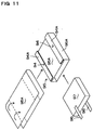
- Fig. 11 is an oblique view showing the manufacturing process of the thin type battery shown in the Fig. 9.
- Fig. 12 is a graph showing the battery capacity maintenance rate.
- Fig. 13 is a plane view and a cross-sectional view of the thin type battery with laminated sheathing of an other embodiment of the present invention.
- Fig. 14 is a cross-sectional view of the collector terminal part of the thin type battery shown in the Fig. 13.
- Fig. 15 is a plane view and a cross-sectional view of the thin type battery with laminated sheathing of an other embodiment of the present invention.
- Fig, 16 is a cross-sectional view of the collector terminal part of the thin type battery shown in the Fig. 15.
- Fig. 17 is an oblique view of the thin type battery of an other embodiment of the present invention.
- Fig. 18 is a plane view of the thin type battery of further an other embodiment of the present invention.
- Fig. 19 is an oblique view showing an example of the electricity generating element built-in in the thin type battery.
- Fig. 20 is a front view showing the pressed condition of the laminated sheathing with the built-in electricity generating element shown in the fig. 19.
- Fig. 21 is an oblique view showing the manufacturing process of the thin type battery of another embodiment of the present invention.
- Fig. 22 is an oblique view showing the manufacturing process of the thin type battery of another embodiment of the present invention.
- Fig. 23 is an oblique view showing the manufacturing process of the thin type battery of another embodiment of the present invention.
- Fig. 24 is an oblique view showing the manufacturing process of the thin type battery of another embodiment of the present invention.
- Fig. 25 is an oblique view showing the manufacturing process of the thin type battery of another embodiment of the present invention.
- Fig. 26 is an oblique view showing the manufacturing process of the thin type battery of another embodiment of the present invention.
- Fig. 27 is an oblique view showing the manufacturing process of the thin type battery of another embodiment of the present Invention.
- Fig. 28 is an oblique view showing the manufacturing process of the thin type battery of another embodiment of the present invention.
- the thin type battery shown in the Figs. 4 to 6 has the electricity generating element built-in the inside of the sealed chamber of the laminated sheathing 45.
- 41 is the positive electrode
- 42 is the negative electrode
- 43 is the electrolytic layer
- 44 is the sealing part of the laminated sheathing
- 45 is the laminated sheathing
- 48 is the collector terminals.
- the thin type battery is a lithium polymer rechargeable battery or a lithium ion rechargeable battery.
- the lithium polymer rechargeable battery uses a solid electrolyte or a gel type electrolyte at normal temperature.
- the lithium polymer rechargeable battery uses the following combinations as to the positive electrode and the negative electrode.
- the lithium ion rechargeable battery uses an electrolyte obtained from a solvent and a solute of LiPF 6 etc, the followings are used as to the positive and negative electrodes.
- the laminated film 45A shown in this figure has a three layer structure composed of the polypropylene film 45c, the aluminum foil 45b and the polypropylene film 45c; the polypropylene films 45c that are the same polypropylene films are laminated on both sides of the aluminum foil 45b.
- the thin type battery that is a lithium polymer rechargeable battery or a lithium ion rechargeable battery, is manufactured as follows.
- each layer of the laminated films 45A is as follows; the primary polypropylene film 45c located at the inner side of the laminated sheathing 45, is 50 ⁇ m, the aluminum foil 45b is 20 ⁇ m, the secondary polypropylene film 45c located at the external side of the laminated sheathing 45, is 80 ⁇ m.
- a metamerism of the polypropylene film is used to glue the interface between the aluminum foil 45b and the polypropylene films 45c.
- the thin type battery is manufactured like the laminated sheathing shown in the Figs. 4 to 6 according to the following process.
- the overall thickness of the thin type battery manufactured by the here-over process is set at 1.5 mm.
- the thin type battery shown in the Fig. 9 and Fig. 10, uses the same electricity generating element 97 built-in the laminated sheathing 95 as in the embodiment 1.
- the positive electrode is numbered 91
- the negative electrode 92 the electrolytic layer 93, and 94 the sealing part of the laminated film 95A.
- the laminated film 95A has a three layer structure composed of the polyethylene film 95d, the aluminum foil 95b and the polyethylene film 95d.
- the polyethylene films 95d laminated on both sides of the aluminum foil 95b, are made of the same material.
- the primary polyethylene film 95d (inner side) is 30 ⁇ m thick
- the aluminum foil 95b is 9 ⁇ m thick
- the secondary polyethylene film 95d (external side) is 80 ⁇ m thick.
- a polyethylene metamerism is used at the glued interface.
- the thin type battery shown in the Fig. 9 and Fig. 10 is manufactured as follows.
- the overall thickness of the thin type battery manufactured in the here-over conditions is 1.7 mm.
- the thin type battery is manufactured, as shown in the Fig. 1 and Fig. 2, by heat weld of the laminated films 5A at the outer circumference of the electricity generating element 7.
- the electricity generating element 7 is the same as the one of the embodiment 1.
- the three layer structure of polyester film 5a, aluminum foil 5b and polypropylene film 5c are used as to the laminated film 5A with a 60 ⁇ m thick polypropylene film 5c, a 9 ⁇ m thick aluminum foil 5b and a 20 ⁇ m thick polyester film 5a.
- a urethane type glue is used to glue the interface.
- This laminated film 5A is heat welded so that the polyester film 5a is located outwards.
- the width of the sealing part 4 heat depositing the overlapping part of the laminated film 5A around the electricity generating element 7, is 10 mm.
- the electricity generating element 7 mounted in advance in an argon atmosphere is introduce between the laminated film 5A, then the laminated film 5A is heat welded around the electricity generating element 7 realizing the thin type battery.
- the thickness of the completed thin type battery was 1.5 mm.
- the diagram 12 shows the measurement of the battery capacity maintenance rate of the thin type battery that has been manufactured as a test in the embodiments and the comparison. But, this diagram compares the characteristics of the embodiments and the comparison of the thin type battery that is a lithium polymer rechargeable battery. From this diagram, the thin type battery of the embodiments 1 and 2 of the present invention compared with the thin type battery of the comparison has a battery capacity maintenance rate that has remarkably improved. But, the maintenance rate of the battery capacity of this diagram measured when the test battery is kept still at 60 degrees, shows a proportional reduction of the battery capacity.
- the thin type battery of lithium ion rechargeable battery type shows the same tendency as the diagram 12.
- the thin type battery of the laminated sheathing of the present invention does not specify the structure of the sealing part of the laminated sheathing in the here-over mentioned embodiments.
- the laminated sheathing overlaps and heat deposit the laminated film 135A on the entire circumference of the electricity generating element 137, and it is possible to have a structure obtained by folding and gluing the 4 heat welded overlapped parts on the upper face of the electricity generating element 137.
- the thin type battery shown in this figure has the primary sealing part 134A extending vertically according to this figure and the secondary sealing part 134B extending right-left, around the electricity generating element 137.
- the terminal collectors 136 are bent together with the overlapping part that has been heat welded and protrude outwards, as shown in the Fig. 14.
- the positive electrode is numbered 131, the negative electrode 132, the electrolytic layer 133, and 134 the laminated sheathing.
- the thin type battery of the present invention it is also possible to fold and heat deposit the laminated film 155A overlapping at the lower face of the electricity generating element 157 at the surface of the laminated film 155A overlapping at the upper face of the electricity generating element 157.
- the thin type battery shown in this figure has the primary sealing part 154A extending vertically in this figure, and the secondary sealing part 154B extending right-left, around the electricity generating element 157.
- the collector terminals 156 protrude outwards between the laminated films 155A overlapping vertically the electricity generating element 157.
- the positive electrode is numbered 151, the negative electrode 152, the electrolytic layer 153, and the laminated sheathing 155.
- the thin type battery of the present invention shown in the Fig. 17 it is possible to set the primary sealing part 174A of the laminated sheathing 175 at the surface of the electricity generating element 177 and to set the secondary sealing part 174B protruding out of the both extremities of the electricity generating element 177.
- the thin type battery of this type is manufactured according to the here-under process.
- the collector terminals 176 of the positive electrode and the negative electrode of the thin type battery of the here-over embodiment are crimped in one of the secondary sealing parts 174B and protrude outwards. As shown in the Fig. 18, the collector terminals of the positive electrode and the negative electrode can separately protrude from both of the secondary sealing parts 184B.
- 185 refers to the laminated sheathing, 185A to the laminated film, 184A to the primary sealing part, 184B to the secondary sealing part.
- the electricity generating element to be introduced into the sealed chamber of the laminated sheathing can also have the structure of flat positive and negative electrodes overlapping in plural layers, but as shown in the Fig. 19, the overlapping materials of the positive electrode 191 and the negative electrode 192 can also have the structure of spiral shape roll.
- the collector terminals 196 are electrically connected to the positive electrode 191 and to the negative electrode 192.
- the thin type battery that can be built-in with the spiral shape electricity generating element 197 includes the electricity generating element 197 inside the laminated sheathing 195 connected in a tubular shape by depositing the laminated film 195A at the primary sealing part 194A, and can also be pressed from both sides to obtain a thin form.
- the thin type battery of the present invention can be manufactured by the following process.
- the thin type battery manufactured according to the here-over process can realize a globally thin laminated sheathing with a sealed tubular shape. Furthermore, it is characterized in that the electrolyte to be poured in is surely prevented to flow outside from the folded part of the laminated film 215A because the corners of the secondary sealing part 214B of the side that does not crimp the collector terminals is heat welded.
- the inner face of the secondary sealing part that crimps the collector terminals can also be airtightly sealed by spreading an adhesive material.
- the secondary sealing part that is to be glued by mean of an adhesive material has the particularity to allow gluing without any gap because the adhesive material fills up the interval between the collector terminals and the laminated film.
Abstract
Description
Claims (17)
- A thin type battery comprising :wherein collector terminals are connected to said positive electrode and said negative electrode, respectively, of said electricity generating element, protrude to an outside of said laminated sheathing, and at least one of said collector terminals is crimped in an airtight manner at said secondary sealing part of said laminated film.a laminated sheathing comprising a laminated film configured to form an airtight sealed chamber;an electricity generating element mounted in said sealed chamber and having a positive electrode and a negative electrode;wherein said laminated film is overlapped on and adhered to itself at a surface of said electricity generating element to form an elongated primary sealing part and an elongated secondary sealing part extending perpendicular to said elongated primary sealing part; and
- A thin type battery with a laminated sheathing as recited in claim 1 wherein the primary sealing part is set in one line at the surface of the electricity generating element.
- A thin type battery with a laminated sheathing as recited in claim 2 wherein the primary sealing part is set at almost the center of the surface of the electricity generating element.
- A thin type battery with a laminated sheathing as recited in claim 1 wherein the primary sealing parts are set on both sides of the electricity generating element.
- A thin type battery with a laminated sheathing as recited in claim 1 wherein the outer shape of the laminated sheathing is rectangular with the primary sealing part longer than the secondary sealing part.
- A thin type battery with a laminated sheathing as recited in claim 1 wherein the secondary sealing part is set at both extremities of the laminated sheathing with the secondary sealing part protruding outside the electricity generating element.
- A thin type battery with a laminated sheathing as recited in claim 1 wherein the positive and negative electrodes of the collector terminals are crimped at one of the secondary sealing parts and protruding outside the laminated sheathing.
- A thin type battery with a laminated sheathing as recited in claim 7 wherein the secondary sealing part that crimps the collector terminals and also the secondary sealing part that does not crimp the collector terminals, are both protruding outside the electricity generating element.
- A thin type battery with a laminated sheathing as recited in claim 7 wherein the secondary sealing part that crimps the collector terminals is protruding outside the electricity generating element, and the secondary sealing part that does not crimp the collector terminals is folded and overlapped at the surface of the electricity generating element.
- A thin type battery with a laminated sheathing as recited in claim 9 wherein the corners of the secondary sealing part to be folded and overlapped on the surface of the electricity generating element, are heat welded.
- A thin type battery with a laminated sheathing as recited in claim 1 wherein the collector terminals of the positive electrode and the negative electrode are separately crimped and protruding outside of both the secondary sealing parts of the laminated sheathing.
- A thin type battery with a laminated sheathing as recited in claim 1 wherein the laminated films are heat welded at the sealing part because aluminum is laminated and glued between the thermally deformable plastic films and because the plastic films that are to be laminated and glued on both sides of the aluminum, are the same plastic films.
- A thin type battery with a laminated sheathing as recited in claim 1 wherein adhesive material is filled between the collector terminals and the laminated films.
- A thin type battery with a laminated sheathing as recited in claim 1 wherein the thin type battery is a lithium polymer rechargeable battery.
- A thin type battery with a laminated sheathing as recited in claim 1 wherein the thin type battery is a lithium ion rechargeable battery.
- A thin type battery with a laminated sheathing as recited in claim 1 wherein the electricity generating element laminates the positive electrode and the negative electrode in a flat manner.
- A thin type battery with a laminated sheathing as recited in claim 1 wherein the electricity generating element is a spiral shape roll laminating the positive electrode and the negative electrode.
Applications Claiming Priority (6)
| Application Number | Priority Date | Filing Date | Title |
|---|---|---|---|
| JP31772796 | 1996-11-28 | ||
| JP317727/96 | 1996-11-28 | ||
| JP31772796 | 1996-11-28 | ||
| JP320989/97 | 1997-11-21 | ||
| JP32098997 | 1997-11-21 | ||
| JP9320989A JPH10214606A (en) | 1996-11-28 | 1997-11-21 | Thin type battery of laminated armor body |
Publications (2)
| Publication Number | Publication Date |
|---|---|
| EP0845821A2 true EP0845821A2 (en) | 1998-06-03 |
| EP0845821A3 EP0845821A3 (en) | 2000-08-23 |
Family
ID=26569123
Family Applications (1)
| Application Number | Title | Priority Date | Filing Date |
|---|---|---|---|
| EP97309504A Withdrawn EP0845821A3 (en) | 1996-11-28 | 1997-11-25 | Thin type battery with laminated sheathing |
Country Status (3)
| Country | Link |
|---|---|
| US (1) | US6106973A (en) |
| EP (1) | EP0845821A3 (en) |
| JP (1) | JPH10214606A (en) |
Cited By (12)
| Publication number | Priority date | Publication date | Assignee | Title |
|---|---|---|---|---|
| FR2773912A1 (en) * | 1998-01-21 | 1999-07-23 | Sanyo Electric Co | THIN TYPE WATERPROOF CELL ELEMENT, AND MANUFACTURING METHOD THEREOF |
| EP0997955A1 (en) * | 1998-10-30 | 2000-05-03 | Sony Corporation | Non-aqueous electrolyte flat cell with laminated sheathing |
| WO2000041252A2 (en) * | 1999-01-08 | 2000-07-13 | Danionics A/S | Arrangement of electrochemical cells |
| WO2000059063A1 (en) * | 1999-03-26 | 2000-10-05 | Matsushita Electric Industrial Co., Ltd. | Laminate sheath type battery |
| EP1045463A1 (en) * | 1999-04-14 | 2000-10-18 | Alcatel | A method of fabricating an electrochemical cell battery and an improved cell package |
| EP1120849A2 (en) | 2000-01-27 | 2001-08-01 | Sony Corporation | Gel electrolyte battery |
| DE10345564A1 (en) * | 2003-09-30 | 2005-04-28 | Bullith Batteries Ag | Packaging with electrochemical cell in gas-tight casing, includes sealing region extending predominantly into tray |
| EP2017909A1 (en) * | 2007-07-20 | 2009-01-21 | Samsung SDI Co., Ltd. | Pouch-type secondary battery |
| CN100459225C (en) * | 1999-03-26 | 2009-02-04 | 松下电器产业株式会社 | Laminate sheath type battery |
| EP2269246B1 (en) * | 2008-04-21 | 2013-08-07 | Robert Bosch GmbH | Energy storage module and power tool comprising at least one energy storage module |
| EP2884560A1 (en) * | 2013-12-16 | 2015-06-17 | Samsung SDI Co., Ltd. | Flexible secondary battery |
| JP2015228319A (en) * | 2014-05-30 | 2015-12-17 | 藤森工業株式会社 | Battery container, film packaged battery, and manufacturing method thereof |
Families Citing this family (60)
| Publication number | Priority date | Publication date | Assignee | Title |
|---|---|---|---|---|
| JP3583589B2 (en) * | 1997-08-26 | 2004-11-04 | 東芝電池株式会社 | Sheet type battery |
| JP4518583B2 (en) * | 1998-08-19 | 2010-08-04 | ソニー株式会社 | Solid electrolyte battery |
| JP3980505B2 (en) * | 1998-08-31 | 2007-09-26 | 株式会社東芝 | Thin lithium ion secondary battery |
| JP2000090975A (en) * | 1998-09-09 | 2000-03-31 | Sony Corp | Thin battery and sealing method thereof |
| JP2000090994A (en) * | 1998-09-11 | 2000-03-31 | Matsushita Electric Ind Co Ltd | Lead bonding construction and battery pack using the same |
| JP2000100396A (en) * | 1998-09-18 | 2000-04-07 | Fujimori Kogyo Co Ltd | Secondary battery |
| JP2000106167A (en) * | 1998-09-30 | 2000-04-11 | Mitsubishi Electric Corp | Battery |
| US7297441B2 (en) * | 1998-10-23 | 2007-11-20 | Sony Corporation | Nonaqueous-electrolyte secondary battery |
| JP4193247B2 (en) * | 1998-10-30 | 2008-12-10 | ソニー株式会社 | Non-aqueous electrolyte battery and manufacturing method thereof |
| US6797429B1 (en) * | 1998-11-06 | 2004-09-28 | Japan Storage Battery Co, Ltd. | Non-aqueous electrolytic secondary cell |
| JP4701464B2 (en) * | 1998-12-04 | 2011-06-15 | 株式会社Gsユアサ | battery |
| JP4193248B2 (en) * | 1998-11-10 | 2008-12-10 | ソニー株式会社 | Gel electrolyte battery |
| JP3900507B2 (en) * | 1998-11-30 | 2007-04-04 | ソニー株式会社 | Non-aqueous electrolyte battery |
| JP4385425B2 (en) * | 1999-02-19 | 2009-12-16 | ソニー株式会社 | Solid electrolyte battery and manufacturing method thereof |
| JP3806540B2 (en) * | 1999-03-30 | 2006-08-09 | 三洋電機株式会社 | Method for manufacturing thin battery using laminate outer package |
| JP2000285885A (en) * | 1999-03-30 | 2000-10-13 | Japan Storage Battery Co Ltd | Manufacture of battery |
| KR100319108B1 (en) * | 1999-04-16 | 2001-12-29 | 김순택 | Case of the secondary battery |
| JP4438137B2 (en) * | 1999-09-14 | 2010-03-24 | 株式会社ジーエス・ユアサコーポレーション | Battery manufacturing method |
| JP2001110452A (en) * | 1999-10-07 | 2001-04-20 | Sony Corp | Manufacturing method of nonaqueous electrolytic battery |
| CN1193442C (en) * | 1999-12-17 | 2005-03-16 | 大日本印刷株式会社 | Packaging material for polymer cell and method for producing same |
| US6482544B1 (en) * | 2000-06-30 | 2002-11-19 | Mitsubishi Denki Kabushiki Kaisha | Battery package |
| JP4686823B2 (en) * | 2000-07-10 | 2011-05-25 | 株式会社Gsユアサ | Sealed battery |
| US20020192549A1 (en) * | 2000-12-07 | 2002-12-19 | Tdk Corporation | Electrode composition, and lithium secondary battery |
| WO2002075457A1 (en) * | 2001-03-21 | 2002-09-26 | Fuji Xerox Co., Ltd. | Developing method for electrophotographic image and developing device, and printing device using the developing device |
| US6844109B2 (en) * | 2001-12-18 | 2005-01-18 | Ngk Spark Plug Co., Ltd. | Li-ion and/or Li-ion polymer battery with edge protectors |
| KR100472504B1 (en) * | 2002-06-17 | 2005-03-10 | 삼성에스디아이 주식회사 | Pouch type secondary battery with improved reinforcement structure |
| KR100958647B1 (en) * | 2002-12-18 | 2010-05-20 | 삼성에스디아이 주식회사 | Pouch type secondary battery |
| US7179562B2 (en) * | 2003-02-14 | 2007-02-20 | Quallion Llc | Battery electrode assembly and fabrication method therefor |
| JP3789438B2 (en) * | 2003-03-03 | 2006-06-21 | Necラミリオンエナジー株式会社 | Film outer battery |
| US7776468B2 (en) * | 2004-03-18 | 2010-08-17 | The Gillette Company | Wafer alkaline cell |
| US7413828B2 (en) * | 2004-03-18 | 2008-08-19 | The Gillette Company | Wafer alkaline cell |
| US7820329B2 (en) * | 2004-03-18 | 2010-10-26 | The Procter & Gamble Company | Wafer alkaline cell |
| US7531271B2 (en) * | 2004-03-18 | 2009-05-12 | The Gillette Company | Wafer alkaline cell |
| JP5050858B2 (en) * | 2006-01-24 | 2012-10-17 | 株式会社村田製作所 | Chip battery |
| JP5382130B2 (en) * | 2009-11-02 | 2014-01-08 | トヨタ自動車株式会社 | Method for producing solid electrolyte battery |
| US9577284B2 (en) * | 2010-02-26 | 2017-02-21 | GM Global Technology Operations LLC | Fuel cell stack enclosure |
| JP5987336B2 (en) * | 2011-03-25 | 2016-09-07 | 日本電気株式会社 | Secondary battery |
| US9281538B2 (en) * | 2011-04-11 | 2016-03-08 | Panasonic Intellectual Property Management Co., Ltd. | Thin battery and battery device |
| JP5743791B2 (en) * | 2011-08-02 | 2015-07-01 | 三洋電機株式会社 | Power supply device and vehicle equipped with power supply device |
| JP5644718B2 (en) * | 2011-08-24 | 2014-12-24 | 大日本印刷株式会社 | Sealing method using sealing head for polymer battery packaging |
| US8989821B2 (en) | 2011-08-31 | 2015-03-24 | Apple Inc. | Battery configurations for electronic devices |
| US9209448B2 (en) * | 2011-09-16 | 2015-12-08 | Changs Ascending Enterprise Co., Ltd. | Conductive connection structure for secondary batteries |
| JP5533828B2 (en) * | 2011-09-21 | 2014-06-25 | 株式会社Gsユアサ | battery |
| US9343716B2 (en) | 2011-12-29 | 2016-05-17 | Apple Inc. | Flexible battery pack |
| US9812680B2 (en) | 2012-08-30 | 2017-11-07 | Apple Inc. | Low Z-fold battery seal |
| US9136510B2 (en) | 2012-11-26 | 2015-09-15 | Apple Inc. | Sealing and folding battery packs |
| EP2874198B1 (en) * | 2013-11-15 | 2017-11-01 | Saft Groupe S.A. | Battery design with bussing integral to battery assembly |
| US9593969B2 (en) | 2013-12-27 | 2017-03-14 | Apple Inc. | Concealed electrical connectors |
| US9479007B1 (en) | 2014-02-21 | 2016-10-25 | Apple Inc. | Induction charging system |
| US20150255776A1 (en) | 2014-03-06 | 2015-09-10 | Apple Inc. | Battery Pack System |
| US9455582B2 (en) | 2014-03-07 | 2016-09-27 | Apple Inc. | Electronic device and charging device for electronic device |
| US9917335B2 (en) | 2014-08-28 | 2018-03-13 | Apple Inc. | Methods for determining and controlling battery expansion |
| JP6426959B2 (en) * | 2014-09-25 | 2018-11-21 | 昭和電工パッケージング株式会社 | Tube type exterior body for power storage device and power storage device |
| US10056642B2 (en) | 2014-11-20 | 2018-08-21 | Ford Global Technologies, Llc | Battery assembly including battery cells wrapped with thermally conductive film |
| US10629857B2 (en) | 2015-02-12 | 2020-04-21 | Semiconductor Energy Laboratory Co., Ltd. | Secondary battery and electronic device |
| US10181617B2 (en) | 2015-12-14 | 2019-01-15 | Johnson Controls Technology Company | Patterned crimp for battery collector attachment |
| KR102016643B1 (en) * | 2016-09-19 | 2019-08-30 | 주식회사 엘지화학 | Rechargeable battery |
| US10637017B2 (en) | 2016-09-23 | 2020-04-28 | Apple Inc. | Flexible battery structure |
| JP7246889B2 (en) * | 2018-10-19 | 2023-03-28 | 株式会社エンビジョンAescジャパン | Assembled battery and manufacturing method thereof |
| WO2021256403A1 (en) * | 2020-06-15 | 2021-12-23 | 株式会社村田製作所 | Solid-state battery and method for producing solid-state battery |
Citations (4)
| Publication number | Priority date | Publication date | Assignee | Title |
|---|---|---|---|---|
| US4092464A (en) * | 1976-07-19 | 1978-05-30 | P. R. Mallory & Co. Inc. | Flexible cells and batteries formed therefrom |
| US4664994A (en) * | 1984-04-26 | 1987-05-12 | Matsushita Electric Industrial Co., Ltd. | Enclosed lead storage battery and process for producing the same |
| US4758482A (en) * | 1986-12-19 | 1988-07-19 | Shin-Kobe Electric Machinery Co., Ltd. | Enclosed type lead batteries and method for producing the same |
| EP0862227A1 (en) * | 1997-02-26 | 1998-09-02 | Sony Corporation | Thin type electric cell |
Family Cites Families (11)
| Publication number | Priority date | Publication date | Assignee | Title |
|---|---|---|---|---|
| US3734780A (en) * | 1971-06-25 | 1973-05-22 | Esb Inc | Flat cell battery with both terminals on one face |
| DE3373748D1 (en) * | 1983-06-23 | 1987-10-22 | Matsushita Electric Ind Co Ltd | Flat battery |
| JPS60211763A (en) * | 1984-04-05 | 1985-10-24 | Hitachi Maxell Ltd | Manufacture of thin type battery |
| JPH0654683B2 (en) * | 1987-11-24 | 1994-07-20 | 新神戸電機株式会社 | Manufacturing method of sealed lead-acid battery |
| US4997732A (en) * | 1989-03-30 | 1991-03-05 | Mhb Joint Venture | Battery in a vacuum sealed enveloping material and a process for making the same |
| US5227264A (en) * | 1991-02-14 | 1993-07-13 | Hydro-Quebec | Device for packaging a lithium battery |
| US5422200A (en) * | 1994-07-27 | 1995-06-06 | Hope; Stephen F. | Battery packaging construction for alkali metal multicell batteries |
| JP3617081B2 (en) * | 1994-09-09 | 2005-02-02 | ソニー株式会社 | Thin card battery |
| JP3512551B2 (en) * | 1996-01-30 | 2004-03-29 | 株式会社リコー | Rechargeable battery |
| JPH1012200A (en) * | 1996-06-18 | 1998-01-16 | Yuasa Corp | Battery |
| JPH11213964A (en) * | 1998-01-21 | 1999-08-06 | Sanyo Electric Co Ltd | Thin battery and its manufacture |
-
1997
- 1997-11-21 JP JP9320989A patent/JPH10214606A/en active Pending
- 1997-11-25 EP EP97309504A patent/EP0845821A3/en not_active Withdrawn
- 1997-11-26 US US08/979,258 patent/US6106973A/en not_active Expired - Fee Related
Patent Citations (4)
| Publication number | Priority date | Publication date | Assignee | Title |
|---|---|---|---|---|
| US4092464A (en) * | 1976-07-19 | 1978-05-30 | P. R. Mallory & Co. Inc. | Flexible cells and batteries formed therefrom |
| US4664994A (en) * | 1984-04-26 | 1987-05-12 | Matsushita Electric Industrial Co., Ltd. | Enclosed lead storage battery and process for producing the same |
| US4758482A (en) * | 1986-12-19 | 1988-07-19 | Shin-Kobe Electric Machinery Co., Ltd. | Enclosed type lead batteries and method for producing the same |
| EP0862227A1 (en) * | 1997-02-26 | 1998-09-02 | Sony Corporation | Thin type electric cell |
Non-Patent Citations (3)
| Title |
|---|
| PATENT ABSTRACTS OF JAPAN vol. 013, no. 390 (E-813), 29 August 1989 (1989-08-29) & JP 01 137570 A (SHIN KOBE ELECTRIC MACH CO LTD), 30 May 1989 (1989-05-30) * |
| PATENT ABSTRACTS OF JAPAN vol. 1997, no. 12, 25 December 1997 (1997-12-25) & JP 09 213285 A (RICOH CO LTD), 15 August 1997 (1997-08-15) * |
| PATENT ABSTRACTS OF JAPAN vol. 1998, no. 05, 30 April 1998 (1998-04-30) & JP 10 012200 A (YUASA CORP), 16 January 1998 (1998-01-16) * |
Cited By (21)
| Publication number | Priority date | Publication date | Assignee | Title |
|---|---|---|---|---|
| FR2773912A1 (en) * | 1998-01-21 | 1999-07-23 | Sanyo Electric Co | THIN TYPE WATERPROOF CELL ELEMENT, AND MANUFACTURING METHOD THEREOF |
| KR100661429B1 (en) * | 1998-10-30 | 2006-12-28 | 소니 가부시끼 가이샤 | Non-aqueous Electrolyte Cell |
| EP0997955A1 (en) * | 1998-10-30 | 2000-05-03 | Sony Corporation | Non-aqueous electrolyte flat cell with laminated sheathing |
| US6358644B1 (en) | 1998-10-30 | 2002-03-19 | Sony Corporation | Non-aqueous electolyte cell |
| WO2000041252A2 (en) * | 1999-01-08 | 2000-07-13 | Danionics A/S | Arrangement of electrochemical cells |
| WO2000041252A3 (en) * | 1999-01-08 | 2000-09-28 | Danionics As | Arrangement of electrochemical cells |
| WO2000059063A1 (en) * | 1999-03-26 | 2000-10-05 | Matsushita Electric Industrial Co., Ltd. | Laminate sheath type battery |
| CN100459225C (en) * | 1999-03-26 | 2009-02-04 | 松下电器产业株式会社 | Laminate sheath type battery |
| US6743546B1 (en) | 1999-03-26 | 2004-06-01 | Matsushita Electric Industrial Co., Ltd. | Laminate sheath type battery |
| EP1045463A1 (en) * | 1999-04-14 | 2000-10-18 | Alcatel | A method of fabricating an electrochemical cell battery and an improved cell package |
| US6379838B1 (en) | 1999-04-14 | 2002-04-30 | Alcatel | Cell package |
| EP1120849A3 (en) * | 2000-01-27 | 2004-07-21 | Sony Corporation | Gel electrolyte battery |
| EP1120849A2 (en) | 2000-01-27 | 2001-08-01 | Sony Corporation | Gel electrolyte battery |
| DE10345564A1 (en) * | 2003-09-30 | 2005-04-28 | Bullith Batteries Ag | Packaging with electrochemical cell in gas-tight casing, includes sealing region extending predominantly into tray |
| EP2017909A1 (en) * | 2007-07-20 | 2009-01-21 | Samsung SDI Co., Ltd. | Pouch-type secondary battery |
| US8318341B2 (en) | 2007-07-20 | 2012-11-27 | Samsung Sdi Co., Ltd. | Pouch-type secondary battery |
| EP2269246B1 (en) * | 2008-04-21 | 2013-08-07 | Robert Bosch GmbH | Energy storage module and power tool comprising at least one energy storage module |
| EP2884560A1 (en) * | 2013-12-16 | 2015-06-17 | Samsung SDI Co., Ltd. | Flexible secondary battery |
| CN104716386A (en) * | 2013-12-16 | 2015-06-17 | 三星Sdi株式会社 | Flexible secondary battery |
| US9941492B2 (en) | 2013-12-16 | 2018-04-10 | Samsung Sdi Co., Ltd. | Flexible secondary battery having a bonding portion extending in a lengthwise direction |
| JP2015228319A (en) * | 2014-05-30 | 2015-12-17 | 藤森工業株式会社 | Battery container, film packaged battery, and manufacturing method thereof |
Also Published As
| Publication number | Publication date |
|---|---|
| US6106973A (en) | 2000-08-22 |
| EP0845821A3 (en) | 2000-08-23 |
| JPH10214606A (en) | 1998-08-11 |
Similar Documents
| Publication | Publication Date | Title |
|---|---|---|
| EP0845821A2 (en) | Thin type battery with laminated sheathing | |
| CN100483835C (en) | Pouch type lithium secondary battery | |
| US8697277B2 (en) | Film-clad battery and method of producing film-clad battery | |
| JP5591569B2 (en) | Square battery, method for manufacturing the same, and assembled battery using the same | |
| US10033048B2 (en) | Thin film battery | |
| EP1708214B1 (en) | Electrochemical device | |
| US20060008702A1 (en) | Secondary battery | |
| KR101264419B1 (en) | battery | |
| EP1455400B1 (en) | Film covered battery | |
| US6048639A (en) | Thin type sealed cell and producing method thereof | |
| JP3825593B2 (en) | Manufacturing method of package | |
| EP1530246B1 (en) | Laminated battery | |
| EP1065743A2 (en) | Lithium ion polymer secondary battery and gelatinous polymer electrolyte for sheet battery | |
| CN106463779B (en) | Lithium ion secondary battery | |
| US6371996B1 (en) | Manufacturing method of batteries | |
| JP4304304B2 (en) | Film outer battery | |
| CA2223370A1 (en) | Sheet type lithium secondary battery | |
| EP4044330A1 (en) | Secondary battery | |
| JP7147522B2 (en) | All-solid-state battery and manufacturing method thereof | |
| CN111326707A (en) | Laminated battery and method for manufacturing laminated battery | |
| US11509012B2 (en) | Thin-type battery | |
| JP3869668B2 (en) | Electrochemical device and manufacturing method thereof | |
| JP4237557B2 (en) | Battery pack | |
| JP2003086172A (en) | Secondary battery and its method of manufacture | |
| JP3469470B2 (en) | Cylindrical batteries and capacitors |
Legal Events
| Date | Code | Title | Description |
|---|---|---|---|
| PUAI | Public reference made under article 153(3) epc to a published international application that has entered the european phase |
Free format text: ORIGINAL CODE: 0009012 |
|
| AK | Designated contracting states |
Kind code of ref document: A2 Designated state(s): DE FR GB |
|
| AX | Request for extension of the european patent |
Free format text: AL;LT;LV;MK;RO;SI |
|
| 17P | Request for examination filed |
Effective date: 19980619 |
|
| RIN1 | Information on inventor provided before grant (corrected) |
Inventor name: NARUKAWA, SATOSHI Inventor name: TERAJI, KAZUO Inventor name: NAKANE, IKUROU Inventor name: FUJII, TAKANORI Inventor name: SONOZAKI, TSUTOMU |
|
| PUAL | Search report despatched |
Free format text: ORIGINAL CODE: 0009013 |
|
| AK | Designated contracting states |
Kind code of ref document: A3 Designated state(s): AT BE CH DE DK ES FI FR GB GR IE IT LI LU MC NL PT SE |
|
| AX | Request for extension of the european patent |
Free format text: AL;LT;LV;MK;RO;SI |
|
| RIC1 | Information provided on ipc code assigned before grant |
Free format text: 7H 01M 2/02 A, 7H 01M 2/06 B |
|
| AKX | Designation fees paid |
Free format text: DE FR GB |
|
| STAA | Information on the status of an ep patent application or granted ep patent |
Free format text: STATUS: THE APPLICATION HAS BEEN WITHDRAWN |
|
| 18W | Application withdrawn |
Effective date: 20040301 |
|
| REG | Reference to a national code |
Ref country code: HK Ref legal event code: WD Ref document number: 1006649 Country of ref document: HK |