EP0847737A2 - Stabilized absorbent article - Google Patents
Stabilized absorbent article Download PDFInfo
- Publication number
- EP0847737A2 EP0847737A2 EP97121855A EP97121855A EP0847737A2 EP 0847737 A2 EP0847737 A2 EP 0847737A2 EP 97121855 A EP97121855 A EP 97121855A EP 97121855 A EP97121855 A EP 97121855A EP 0847737 A2 EP0847737 A2 EP 0847737A2
- Authority
- EP
- European Patent Office
- Prior art keywords
- fluid
- absorbent
- stabilizing element
- absorbent article
- inches
- Prior art date
- Legal status (The legal status is an assumption and is not a legal conclusion. Google has not performed a legal analysis and makes no representation as to the accuracy of the status listed.)
- Granted
Links
Images

Classifications
-
- A—HUMAN NECESSITIES
- A61—MEDICAL OR VETERINARY SCIENCE; HYGIENE
- A61F—FILTERS IMPLANTABLE INTO BLOOD VESSELS; PROSTHESES; DEVICES PROVIDING PATENCY TO, OR PREVENTING COLLAPSING OF, TUBULAR STRUCTURES OF THE BODY, e.g. STENTS; ORTHOPAEDIC, NURSING OR CONTRACEPTIVE DEVICES; FOMENTATION; TREATMENT OR PROTECTION OF EYES OR EARS; BANDAGES, DRESSINGS OR ABSORBENT PADS; FIRST-AID KITS
- A61F13/00—Bandages or dressings; Absorbent pads
- A61F13/15—Absorbent pads, e.g. sanitary towels, swabs or tampons for external or internal application to the body; Supporting or fastening means therefor; Tampon applicators
- A61F13/45—Absorbent pads, e.g. sanitary towels, swabs or tampons for external or internal application to the body; Supporting or fastening means therefor; Tampon applicators characterised by the shape
- A61F13/47—Sanitary towels, incontinence pads or napkins
- A61F13/4702—Sanitary towels, incontinence pads or napkins having a reinforcing member
Definitions
- the present invention relates to an absorbent article for absorbing body fluids such as menstrual fluid, vaginal discharge and/or urine, and more particularly, to an absorbent article having a stabilizing element which is resistant to wet collapse, and provides the article with enhanced resistance to bunching and inward collapse due to lateral compressive forces imparted by a user's thighs so that a central absorbent portion of the article maintains contact with the perineal area of the user and thus reduces the probability of leakage and failure.
- body fluids such as menstrual fluid, vaginal discharge and/or urine
- sanitary protection and feminine hygiene products such as sanitary napkins, adult incontinence devices, etc.
- Conventional full-size sanitary protection and feminine hygiene products such as sanitary napkins, adult incontinence devices, etc., typically contain an absorbent element, a fluid-pervious body-contacting element and a fluid-impervious undergarment-facing element. These articles are intended to absorb body fluid from the wearer and retain the fluid in order to prevent the fluid from soiling the wearer's garments.
- conventional feminine hygiene articles do not adequately fulfill women's protection requirements.
- Sanitary napkins generally have the capability of absorbing between 50 and 100 grams of fluid. However, soiling of a wearer's garments still occurs even when only 5 to 10 grams of fluid has been deposited on the absorbent articles.
- napkin instability One factor that contributes to poor fit and lack of conformity is napkin instability.
- a compression force is applied to a sanitary napkin (e.g., by the lateral compressive forces of a user's thighs)
- the napkin tends to fold or bunch resulting in a smaller area of contact with the user's body resulting in a gap between the absorbent article and the user's body.
- the napkin center may also become depressed, i.e., move in a direction downward and away from the user's body. Fluid may then travel along the body and bypass the napkin resulting in soiling of the undergarment.
- European Patent No. 091,412 depicts an absorbent product having an absorbent core which is convex in the center and has elasticized side margins.
- U.S. Patent No. 4,770,657 to Ellis also describes a curved sanitary napkin with elasticized side edges.
- WO 88/04547 to Thoren discloses a design in which elastic means are prestretched. This causes the napkin to be resiliently distorted so that the sides assume a convex shape when held against the user's body. Upon application of pressure, the shape will flatten out. However, when the pressure is reduced or eliminated, the napkin resumes its curved shape. Further this design lacks a structural element and, therefore, when wetted, will collapse and move away from the user and cause soiling of the undergarment.
- U.S. Patent No. 4,405,326 to Lenggham describes a design which is similarly deficient.
- U.S. Patent No. 4,217,901 to Bradstreet also describes a crush-resistant sanitary napkin, but does not specifically address the issue of body-fit.
- European Patent Applications 0 335 252 and 0 335 253 to Buell describe a disposable absorbent article having a flexure-resistant, deformation element that is not moisture-sensitive.
- the deformation element has a convex upward configuration when the napkin is worn and pressed inward by the thighs.
- the proposed design relies on the lateral compressive forces of the wearer's thighs to form a convex upward configuration.
- this design is also flawed with respect to maintaining body-fit and conformation since the convex configuration cannot consistently be controlled by thigh movement, as the napkin's ability to conform to the body relies heavily upon placement of the absorbent article and the wearer's anatomy.
- the deformation element is not moisture-sensitive, the deformation element cannot be placed near the pad's surface because it cannot absorb fluid.
- the absorbent material in the pad which is closer to the body than the deformation element will tend to collapse when exposed to fluid, and move away from the body.
- U.S. Patents Nos. 4,631,062 and 4,804,380 to Lassen generally describe self-conforming napkins for partial labial disposition.
- the napkin contains a posterior region, including a raised profile for placement intermediate the wearer's labia majora and a flattened front portion for placement exterior of the clitoris and pubic mons.
- these products would tend to move during wear and can easily become dislodged from the vestibule.
- interlabial napkins tend to be uncomfortable to wear for most women.
- a napkin described in U.S. Patent No. 3,406,689 to Hicks has a dual discrete layer system in which the two pads are separated from one another and are freely movable with respect to each other. The two pads are installed separately, would tend to move and are extremely inconvenient. Fluid may also travel from one pad to the edge of the other, resulting in staining the wearer's undergarment.
- U.S. Patent No. 4,433,972 to Malfitano also contains two pads, although the top pad is hourglass in shape.
- U.S. Patent No. 4,425,130 to Desmarais describes a sanitary napkin having a primary menstrual absorbent pad and a "panty protector" which are joined.
- the panty protector member is intended to protect the user's garments from being soiled by fluids which are expelled from the primary menstrual pad or which inadvertently pass the primary pad.
- this design may encourage fluid to wick to the edge of the panty protector and transfer to the user's garment. It is also possible for the panty protector to fold in and contact the face of the primary menstrual pad. Fluid may then transfer to the user's panty if the panty folds up and around the edges of the panty protector, especially if the panty protector is thin.
- Patent publication No. WO 92/07535 to Visscher and Osborn discloses a liquid pervious spacing structure which moves the top body-facing cover sheet away from the absorbent core of the napkin.
- the spacing structure has an uncompressed and a compressed configuration and an upper and lower portion.
- the components of this construction are unlikely to remain separated when exposed to fluid, due to wet-collapse.
- Fluid migration along the body is a key element of soiling. Fluid migration generally occurs when fluid is not immediately absorbed into an absorbent article. Accordingly, the better an absorbent article can maintain contact with the body, the less likely that the fluid will leak or migrate away from the absorbent article and cause soiling.
- Yet another object of this invention is to provide an absorbent article which is comfortable, resilient, resistant to wet collapse, yet highly absorbent.
- an absorbent article having longitudinal sides and transverse ends, a body-facing surface and a garment-facing surface, the article comprising:
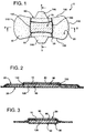
- Figure 1 shows the absorbent article of this invention in plan view from the body-facing side of the article.
- Figure 2 is a cross-sectional view of the absorbent article shown in Figure 1 taken along the line 2-2.
- Figure 3 is a cross-sectional view of the absorbent article shown in Figure 1 taken along the line 3-3.
- Figures 4a and 4b is a side view of a custom jig in an open position (Figure 4a) and in a closed position ( Figure 4b) with upper and lower jaws which are shaped to resemble a human thigh.
- the present invention is directed to an absorbent article which is characterized as having a relatively thick fluid absorbent core, i.e. at least 0.20 inches thick, and an absorbent stabilizing element having a lateral width in a range of from at least 0.5 inches to less than 1.75 inches. It is considered an important feature of the present invention that the stabilizing element have a lateral width in the above critical dimensions. More specifically, it has now been found that the use of an absorbent stabilizing element with these dimensions, in combination with a relatively thick absorbent pulp fluff core, provides enhanced resistance to bunching and inward collapse due to lateral compressive forces imparted by a user's thighs.
- the absorbent article of this invention When placed in an undergarment, the absorbent article of this invention provides a stable, resilient absorbent portion adjacent the labia majora and the vaginal orifice and will permit the central portion of the absorbent article to maintain an intimate fit against the labia majora.
- the stabilizing element provides resilience and resistance to wet-collapse in the area where it is needed, i.e., near the vaginal orifice or urethra, where the body fluid exits the user and impinges on the absorbent article.
- the absorbent articles of this invention provide enhanced leakage protection due to better body fit without sacrificing comfort.
- the absorbent articles 5 of this invention comprise the following elements:
- the fluid-permeable cover sheet 10 may be composed of a woven or non-woven fibrous fabric or an apertured plastic sheet.
- the fibrous fabric may comprise cellulosic fibers such as cotton or rayon, polyolefin fibers such as polyethylene, polypropylene, polyester, and combinations thereof. It may be an entangled fabric, modified-entangled fabric, spun-bond fabric, melt-blown fabric, thermally bonded fabric or chemically bonded fabric.
- Apertured plastic covers are well-known in the art.
- the cover may be selected from sheets known as Dri-weave (U.S. Patent No. 4,324,246), Reticulon® (U.S. Patent No. 4,690,679) or ApexTM (U.S. Patent Application No. 07/744744), all herein incorporated by reference in their entirety.
- suitable fluid-permeable cover sheets include absorbent, porous, dry-laid, nonwoven webs or scrim type materials such as those described in U.S. Pat. No. 4,880,419 to I.S. Ness and in U.S. Pat. No. 3,044,467 to Campau , in U.S. Pat. No. 3,463,154 to Hendricks and in U.S. Pat. No. 3,570,491 to Sneider (herein incorporated by reference in their entirety).
- suitable fluid-permeable cover sheets for use on the absorbent articles of the present invention include nonwovens made from hydrophobic fibers which have been coated with an adhesive or have been subjected to heat and/or pressure to fuse the individual fibers to each other such as those described in U.S. 4,795,455 to T. J. Luceri , in E.P. 354,502 to S. Cadieux , in E.P. 70,163 to A. T. Mays , and in U.S. 4,368,323 to R. P. James (herein incorporated by reference in their entirety). Such materials tend to have only limited absorption thereby allowing passage to lower layers for absorption and retention. As a result, the fluid is wicked away from the body, leaving the surface of the body-contacting layer feeling drier to the touch.
- hydrophobic fibers for the body contacting, or cover, layer allows fluid to pass through to the absorbent layers beneath yet does not retain moisture on the surface layer, thus providing greater comfort since the wearer feels dry for a longer period of time.
- the desirability of such a feature has been disclosed in U.S. 3,838,692 to Levesque (herein incorporated by reference in its entirety) which describes a chemical method of providing porosity to hydrophobic materials.
- the fluid-impermeable backsheet 30 may be a nonwoven or woven fabric treated to become impervious to fluid.
- the backsheet 30 is a plastic sheet comprised of polyethylene or polypropylene. Such layers are disclosed, for example, in U.S. 4,731,066 to Korpman .
- the absorbent core 40 comprises wood pulp fluff, and may optionally contain other cellulosic material or commonly used absorbent materials, and is generally rectangular in shape, and is preferably hourglass shaped wherein a central region of the core, intermediate of the transverse ends of the core, has a width which is narrower than the width of the transverse ends.
- Such cores are taught, for example, in U.S. 4,552,618 to Kopolow and U.S. 4,536,432 to Holtman and in British patent 2,189,705 to Mesek , incorporated herein by reference in their entirety.
- the absorbent core 40 contains additional pulp in the central region to raise this area in an upward, body contacting direction.
- Such additional thickness of pulp may be added between the absorbent core 40 and the stabilizing element 120 .
- This configuration will raise the stabilizing element 120 , and thus the body-facing surface of the absorbent article, closer to the body. Resistance to wet collapse may be enhanced by compressing the additional pulp or optionally the entire absorbent core prior to use.
- the absorbent core 40 may utilize a variety of fluid immobilizing materials, e.g., superabsorbing polymers or sphagnum moss, as a reservoir layer to increase fluid capacity or minimize the overall thickness of the absorbent article.
- fluid immobilizing materials e.g., superabsorbing polymers or sphagnum moss
- these fluid immobilizing materials are not used alone, but in conjunction with cellulosic pulp fluff in order to provide extra absorbency for heavy fluid flow and to provide bulk to keep the article closer to the user's body.
- Such materials are taught by in U.S. 4,507,122 to Y. Levesque ; in U.S. 4,494,963 to S. Dabi ; in U.S. 4,880,419 to I. S. Ness ; in U.S. 4,443,492 to J. Roller ; hereby incorporated by reference in their entirety.
- a transfer layer 80 functions to quickly absorb fluid and hold it until a slower absorbing reservoir layer 90 can accept it.
- a transfer layer 80 be incorporated between the cover sheet 10 and the upper body facing surface of the absorbent core 40 .
- the transfer layer 80 functions to rapidly draw fluid from the fluid-permeable cover sheet 10 and transport it to the absorbent stabilizing element and/or to that portion of the core into which the bulk of the fluid will eventually be absorbed, often referred to as a reservoir layer 90 .
- placement of the transfer layer 80 in the absorbent article would be between the cover sheet 10 and the reservoir layer 90 .
- Acceptable transfer layers 80 are those made from cellulosic materials, such as wood pulp, and an adhesive like binder.
- the basis weight of such materials would range from about 20-200 g/m 2 . More preferably, they would range from about 50-150 g/m 2 . Still more preferably, they would range from about 75-100 g/m 2 .
- Still other suitable materials are discussed in U.S. patent application no. 08/075254, commonly assigned and herein incorporated by reference in its entirety. Such materials, aside from those specifically disclosed in serial no. 08/075254, are well known in the art.
- the stabilizing element 120 is absorbent, resilient and stable, i.e. it maintains its shape in the wet state.
- the stabilizing element 120 should be resistant to wet-collapse in both the lateral or X-direction (herein defined as that direction transverse to the longitudinal edges 100 ) and the Z-direction (herein defined as the direction normal to the cover sheet 10 ).
- the wet collapse in the Z-direction should be less than 10% at 0.2 psi and less than 25% at 0.5 psi. It should have a deformation measurement of less than 15% in the dry state and less than 35% in the wet state in accordance with the Wet and Dry Deformation Tests described in the Examples below.
- Body-contact is important because it helps to inhibit expressed fluid from travelling along the body, e.g, the user's thighs, to soil the user's clothes. Since the stabilizing element 120 is resilient and does not collapse in a wet state, it thus enhances contact between the absorbent article 5 and the user's body at that point where fluid exits the body.
- the resilient, absorbent stabilizing element 120 is preferably flexure resistant. Flexure resistance is generally measured by peak bending stiffness which is more fully discussed in U.S. 5,171,302 to Buell , which is incorporated herein in its entirety.
- the resilient, absorbent stabilizing element 120 of the present invention preferably has a peak bending stiffness of at least 250 grams, preferably greater than 400 grams, and most preferably greater than 600 grams.
- Suitable materials for use as the stabilizing element 120 are selected from the group consisting of sphagnum moss, calendered pulp, a composite of sphagnum moss and calendered pulp, and a composite of calendered pulp and superabsorbent material. These materials may comprise a single layer of the above materials, or may comprise multi-layered laminates. Alternatively, more than one stabilizing element may be used in the absorbent article on the invention. In a most preferred embodiment, the stabilizing element 120 comprises a calendered, multi-layer laminate of sphagnum peat moss which has been sandwiched between an upper and lower layer of pulp fibers.
- the width of the stabilizing element 120 is considered to be a critical element of the present invention.
- the stabilizing element 120 must have a width sufficient to provide stability and resistance to lateral compression to the central portion of the absorbent article. Suitable widths are generally at least 0.5 inches, and less than 1.75 inches. It is preferred that the width of the stabilizing element 120 should generally approximate the dimensions of the labia majora so as to cover the area from which fluid will exit the body. Accordingly, the stabilizing element 120 may have a width in a range of from 0.5 to 1.75 inches, preferably in a range of from 0.75 to 1.25 inches, and most preferably, the stabilizing element 120 should have a width of about 1 inch.
- the length of the stabilizing element 120 is not, per se, critical to the invention, provided of course that it has a length sufficient to provide stability and resistance to lateral compression to the central portion of the absorbent article. Suitable lengths are generally at least about 2 inches, and may be as long as the absorbent article. It is preferred that the length be less than that of the article 5 as a whole, and most preferably, the length and width of the stabilizing element 120 should conform generally to the longitudinal and lateral dimensions of the labia majora so as to cover the area from which fluid will exit the body.
- the stabilizing element 120 may have a length in a range of from 2 to 4 inches, preferably in a range of from 2.5 to 3.5 inches, and most preferably, the stabilizing element 120 should have a length of about 3 inches and a width of about 1 inch. While the lengths of absorbent articles can vary widely, the foregoing preferred lengths generally correspond to less than about 80% of the article 5 length and, more preferably, between about 25-50% of the article 5 length.
- the absorbent core 40 contains a central portion 60 which is located near the center of article 5 , which is defined by the portion between the longitudinal edges 100 and is preferably approximately midway between the transverse edges 110 .
- the central portion 60 would then be positioned, when in use, closest to the point where fluid exits the body. It is considered an important feature of the present invention that the stabilizing element 120 be located adjacent the central portion 60 and be slightly above a plane defined by the longitudinal edges 100 to keep in close contact with the body.
- the fluid-absorbent core contains two preferential bending zones.
- the stabilizing element is preferably in the center portion between the two preferential bending zones wherein the preferential bending zone(s) 50 are in a region outside the transverse ends of the stabilizing element 120 , and are most preferably located at the end(s) 130 of the stabilizing element 120 .
- This allows the absorbent article 5 to cup at the front and back of the user while maintaining an essentially planar or flat configuration in the perineal area (when viewing the longitudinal edges of the article 5 from a longitudinal cross section - see for example Figure 2), thus allowing the stabilizing element 120 in the central portion 60 of the article 5 to conform to the shape of the user's body.
- Most preferred are bending zones 50 which are transverse to the longitudinal axis of the absorbent article 5 and extend from one longitudinal side 100 to the other.
- the bending location and profile of the napkin 5 should be such that the central portion 60 maintains an almost linear longitudinal profile when the ends of the napkin 5 are deflected by a specified amount.
- Example 3 describes the testing for characterization of such preferential bending zones 50 . It is undesirable to have the central portion 60 cup or curve as the napkin 5 would move away from the user and protection would be sacrificed.
- the bending zone 50 may occur by a change in the flexibility of the napkin 5 along its length or it may occur due to a seam, space or embossment anywhere in those portions of the absorbent article 5 including the stabilizing element 120 .
- An additional method of forming the preferential bending zones 50 involves changing the density of the absorbent article 5 such that the density of a stabilizing element 120 having a length which is less than that of the absorbent article is much greater than that of the absorbent core near the transverse ends 110 .
- Changing the density may occur by changing the thickness of the absorbent article 5 in the z-direction or by changing the basis weights of the materials in those parts of the absorbent article 5 adjacent the central portion 60 .
- the absorbent article 5 may also be pre-shaped such that the napkin 5 , prior to use, has a bend located at the preferential bending zones. Such pre-shaping may be accomplished, for example by placing elastic in the flanged side margins of longitudinal edges 100 of the napkin 5 as disclosed in commonly assigned U.S. Patent Application Serial No. 07/766699, and which is hereby incorporated herein by reference in its entirety.
- the absorbent articles of this invention optionally, but preferably, contain attachment tabs and/or side cuffs along the longitudinal sides of the absorbent core.
- These attachment tabs are preferably of dimensions such that their longitudinal edges are shorter than the longitudinal dimensions of the stabilizing element so as not to impede the article's bending along the preferential bending zones located adjacent the stabilizing element.
- Attachment tabs 140 possess adhesive means to hold the article 5 securely to the crotch portion of a user's undergarment so that the stabilizing element 120 maintains intimate contact with the body.
- the attachment tabs 140 also serve to prevent the user's undergarment from contacting the longitudinal sides 100 of the central portion 60 by restraining the side edges of the crotch portion of the user's undergarment. It is preferred, however, that the line of juncture of the attachment tabs 140 not extend beyond the preferential bending zones 50 as this would inhibit bending of the article 5 .
- the attachment tabs 140 may be attached to the longitudinal sides 100 of the article 5 or they may be located on the garment facing side inward from the longitudinal edges as disclosed more fully in U.S. 4,900,320 to McCoy , which incorporated herein by reference in its entirety.
- the line of juncture between the tabs 140 and the napkin 5 be less than 7 inches. It is more preferable that the line of juncture be between 3 and 6 inches.
- the absorbent article 5 be hourglass shaped having arcuate lateral sides with the front and rear portions wider than the central portion 60 . This configuration will also help to stabilize the article 5 by inhibiting shifting from front to back.
- the napkins manufactured for testing in the examples utilized a perforated plastic film (PE/EVA or PE) for the cover (either 0.54 or 1.0 oz/yd 2 ), a transfer layer of 90 g/m 2 airlaid, latex bonded pulp fabric, a wetlaid cellulosic absorbent having a basis weight of 325 g/m 2 , a core of wood pulp fluff underneath (garment side) of a sphagnum moss absorbent board, and a PE/EVA film barrier layer.
- PE/EVA or PE perforated plastic film
- the test described below was designed to simulate the z-direction pressure exerted on a sanitary napkin by a wearer's body. Ideally, the napkin should not collapse in the z-direction when exposed to body fluids, such as menstrual fluid, and body pressure. As demonstrated below, conventional napkins are subject to such collapse.
- Ten napkins were prepared according to the teachings of the specification and compared to ten control napkins, commercially available from Proctor & Gamble under the trademark ALWAYS PLUS MAXI. Each sample was conditioned at 70° ⁇ 2° F and 50 ⁇ 2% RH for 24 hours prior to the test. Such conditions were maintained throughout the testing. The test is further described below. The discussion will detail how each sample was tested.
- the weight on the AMES gauge was then increased to 85.3 grams (this plus the weight of the foot corresponds to a pressure of 0.22 psi).
- the thickness of the sample was again measured and noted as thickness W 2 .
- the center of the sample was marked where the foot of the gauge was resting.
- the sample was removed and cc of synthetic menstrual fluid (SMF) was introduced to the marked area using a syringe.
- SMF synthetic menstrual fluid
- the fluid was added slowly enough so that it did not spill outside the marked area.
- the sample was then immediately placed on the AMES gauge with a weight of 85.3 grams. The thickness of the sample was noted then and for each minute thereafter until there was no change in the thickness of the sample. (In all samples, the thickness ceased to change after 4 minutes). This final thickness was recorded as W 3 .
- %DR (W 1 -W 4 )/W 1 x 100
- Ten additional napkins were prepared according to the teachings of the specification and compared to an additional ten control napkins, commercially available from Proctor & Gamble under the trademark ALWAYS PLUS MAXI. The procedure described above was repeated, except that the test pressure, W 2 was measured using a 226.8 gram weight (corresponding to a total pressure of 0.53 psi).
- Table 1 shows the results obtained under a test pressure of 0.22 psi.
- Table 2 shows the results obtained under a test pressure of 0.53 psi.
- the objective of this test is to determine the deformation resistance of a sanitary napkin or any absorbent article in X-direction (the direction transverse to the longitudinal axis across the plane of the napkin) in terms of a loss in napkin width in both wet and dry states.
- the X-direction Deformation Test method was used to compare the ability of stabilizing inserts to recover after they have been wetted and compressed. Generally the test consists of holding a napkin around the inner cylinder of an Instron deformation test apparatus. It is compressed and then allowed to recover from its deformation for 2 cycles. The loss in width as a result of compression and relaxation is a measure of the deformation resistance of the napkin in X-direction.
- the apparatus used for the test was: 1. Instron Model 1122 Universal Tester; 2. a custom jig (Figure 4) with an 8 inch diameter cylinder and upper and lower jaws which are shaped to resemble a human thigh; 3. 100 Kg load cell; 4. vernier caliper; 5. 25cc graduated cylinder; 6. plexiglas plate (0.511 thick) with an oblong center opening of 0.75" x 1.50"; 7. a 3 inch wide knitted fabric (45% polyester/45% cotton/10% Lycra spandex) which simulates an undergarment crotch; 8.
- Ten napkins were prepared according to the teachings of the specification and ten control napkins, having a stabilizing element with a width greater than 1.75 inches. Each sample was conditioned at 70° ⁇ 2° F and 50 ⁇ 2% RH for 24 hours prior to the test. Such conditions were maintained throughout the testing. The test is further described below. The discussion will detail how each sample was tested.
- the gap between the upper and lower compression surfaces of the custom jig was set at 0.8 inch.
- the return limit on the Instron console was set at 2.2 inches.
- the crosshead speed was set at 5 in./minute.
- the test direction was set to "up” and was pressed so that the crosshead starts moving, stopping when reaching a 3 inch gap spacing (0.8 Inch initial gap + 2.2 inch crosshead travel).
- the instrument was then calibrated by setting the load scale dial to 2 Kg and zeroing the pen on the chart. A 1 Kg weight was then placed on the lower cylinder ring jaw and pen was adjusted using the "calibration knob" so that the pen rested on the 1 Kg line. The 1 Kg weight was then removed. If the pen returns back to the zero position on the chart, it means the instrument has been calibrated. If needed, the "balance knob" is used to bring the pen back to zero.
- the 3 inch wide fabric was cut such that the grain of the fabric was perpendicular to the direction of travel.
- a 4 inch long test sample element was cut from the center of each sanitary napkin to be tested.
- the width of each test sample was the width of the absorbent system in the napkin.
- the width of the test element was measured using a Vernier caliper and was recorded as initial width L 1 .
- the release paper which is on the garment facing side, was removed from the sample.
- the sample was then placed with the garment facing side down into the center of the inner surface of the loop to be formed on the Jig with the side edges of the fabric enveloping the sample edges.
- the sample was secured on the fixture in such a way that it was in direct contact with the jig surface and centered between the curved jaws.
- the cycle counter was set to "2" so that the test sample could be compressed for 2 cycles.
- the return limit on the console was set to "2.25.”
- the maximum and minimum limits were set to "2.20” and "0.00” respectively.
- the test direction was set to "down", and the crosshead speed was set to 5 in./minute.
- the Instron was started. After the crosshead had compressed the sample for 2 cycles and stopped, the sample was is removed and the width again measured and is recorded as final width L 2 .
- Napkins were also tested in the wet state by preparing the samples as described above. However, prior to positioning the sample on the jig, SMF was applied to the center of the test element. This was done by placing the plexiglas plate over the center of the sample. The SMF cc of fluid was poured from the graduated cylinder into the oblong opening of the plate placed on to the sample. Once the fluid was absorbed, the sample was allowed to remain at test conditions for 1 minute and then L 1 and L 2 measured as described above.
- %XD (L 1 -L 2 )/L 1 x 100
- Table 3 shows the results obtained in the dry state.
- Table 4 shows the results obtained in the wet state. % LOSS IN WIDTH IN X-DIRECTION IN DRY STATE Wide Stabilizing Element Narrow Stabilizing Element Width (in) loss (in.) Width (in) loss (in.) Before (L 1 ) After (L 2 ) % loss Before (L 1 ) After (L 2 ) % loss 1.77 1.35 23.7% 0.42 1.08 1.03 4.6% 0.05 1.76 1.42 19.3% 0.34 1.08 1.05 2.8% 0.03 1.76 1.49 15.3% 0.27 1.07 1.04 2.8% 0.03 1.76 1.55 11.9% 0.21 1.07 1.05 1.9% 0.02 1.75 1.49 14.9% 0.26 1.06 1.02 3.8% 0.04 1.76 1.49 15.3% 0.27 1.08 1.01 6.5% 0.07 1.75 1.49 14.9% 0.26 1.03 1.01 1.9% 0.02 1.76 1.27 27.8% 0.49 1.05 1.02 2.9% 0.03 1.76 1.46 17.0% 0.30 1.03 1.03 0.0%
- the napkin as described in this invention offers more resistance to deformation in X-direction as compared to napkins having stabilizing elements with widths outside the critical ranges of the present invention.
- Conventional napkins which mainly consist of pulp, undergo deformation in X-direction in both dry as well as wet states. This phenomenon, called bunching, reduces the effective surface area of the absorbent system available for the capture of bodily fluid. The severe deformation in X-direction, therefore, potentially can lead to higher chances of undergarment staining.
- the data indicate that narrow stabilizing elements resist deformation better than do wide stabilizing elements, and are likely to experience far less loss in width than wider inserts when used. This is consistent with what was seen in returned pad in-use testing.
- the narrow insert recovered to a width very close to its initial width, and the surface of the napkin was generally smooth and without creases.
- the wider stabilizing element had lost width, and this loss results in the element buckling away from the body. By creasing away from the body, fit is impaired, and the absorbent material does not maintain intimate contact with the perineal area of the wearer.
- This loss in fit can result in discomfort (from bulkiness), a feeling of wetness (as the absorbent is not directly against the wearer), and ultimately can result in leakage (from fluid travelling along the body).
Abstract
Description
| TEST PRESSURE AT 0.22 PSI | ||||
| Test | Control | |||
| %RT | %DR | %RT | %DR | |
| 7.496 | 4.210 | 30.769 | 30.320 | |
| 7.192 | 5.980 | 29.725 | 28.012 | |
| 3.580 | -1.300 | 26.375 | 26.179 | |
| 5.187 | -1.408 | 29.566 | 23.994 | |
| 5.650 | 1.284 | 24.296 | 21.407 | |
| 3.571 | -3.102 | 24.160 | 23.566 | |
| 10.069 | 4.232 | 23.414 | 24.606 | |
| 6.666 | 0.160 | 24.437 | 23.557 | |
| 4.566 | -2.215 | 23.455 | 22.606 | |
| 6.593 | -0.356 | 23.411 | 22.186 | |
| Mean | 6.057 | 0.747 | 25.961 | 24.643 |
| S.D. | 1.988 | 3.090 | 2.945 | 2.776 |
| TEST PRESSURE AT 0.53 PSI | ||||
| Test | Control | |||
| %RT | %DR | %RT | %DR | |
| 24.750 | 23.279 | 36.538 | 32.132 | |
| 26.615 | 22.684 | 37.681 | 31.288 | |
| 28.740 | 27.632 | 36.501 | 35.453 | |
| 27.490 | 25.333 | 34.904 | 34.407 | |
| 26.556 | 27.682 | 35.088 | 27.190 | |
| 23.390 | 23.611 | 38.021 | 37.215 | |
| 19.408 | 17.139 | 36.678 | 38.587 | |
| 21.839 | 17.949 | 37.343 | 29.566 | |
| 18.868 | 15.120 | 35.528 | 34.153 | |
| 22.901 | 20.886 | 39.082 | 34.894 | |
| Mean | 24.056 | 22.131 | 36.736 | 33.489 |
| S.D. | 3.370 | 4.324 | 1.335 | 3.476 |
| % LOSS IN WIDTH IN X-DIRECTION IN DRY STATE | |||||||
| Wide Stabilizing Element | Narrow Stabilizing Element | ||||||
| Width (in) | loss (in.) | Width (in) | loss (in.) | ||||
| Before (L1) | After (L2) | % loss | Before (L1) | After (L2) | % loss | ||
| 1.77 | 1.35 | 23.7% | 0.42 | 1.08 | 1.03 | 4.6% | 0.05 |
| 1.76 | 1.42 | 19.3% | 0.34 | 1.08 | 1.05 | 2.8% | 0.03 |
| 1.76 | 1.49 | 15.3% | 0.27 | 1.07 | 1.04 | 2.8% | 0.03 |
| 1.76 | 1.55 | 11.9% | 0.21 | 1.07 | 1.05 | 1.9% | 0.02 |
| 1.75 | 1.49 | 14.9% | 0.26 | 1.06 | 1.02 | 3.8% | 0.04 |
| 1.76 | 1.49 | 15.3% | 0.27 | 1.08 | 1.01 | 6.5% | 0.07 |
| 1.75 | 1.49 | 14.9% | 0.26 | 1.03 | 1.01 | 1.9% | 0.02 |
| 1.76 | 1.27 | 27.8% | 0.49 | 1.05 | 1.02 | 2.9% | 0.03 |
| 1.76 | 1.46 | 17.0% | 0.30 | 1.03 | 1.03 | 0.0% | 0 |
| 1.75 | 1.46 | 16.6% | 0.29 | 1.05 | 1.01 | 3.8% | 0.04 |
| 1.76 | 1.54 | 12.5% | 0.22 | 1.05 | 1.01 | 3.8% | 0.04 |
| 1.77 | 1.37 | 22.6% | 0.40 | 1.03 | 1.00 | 2.9% | 0.03 |
| 1.76 | 1.59 | 9.7% | 0.17 | 1.04 | 1.01 | 2.9% | 0.03 |
| 1.75 | 1.43 | 18.3% | 0.32 | 1.03 | 0.99 | 3.9% | 0.04 |
| 1.75 | 1.5 | 14.3% | 0.25 | 1.05 | 1.02 | 2.9% | 0.03 |
| 1.75 | 1.49 | 14.9% | 0.26 | 1.01 | 1.00 | 1.0% | 0.01 |
| 1.75 | 1.51 | 13.7% | 0.24 | 1.03 | 1.00 | 2.9% | 0.03 |
| 1.76 | 1.43 | 18.8% | 0.33 | 1.04 | 1.01 | 2.9% | 0.03 |
| 1.76 | 1.46 | 17.0% | 0.30 | 1.03 | 1.01 | 1.9% | 0.02 |
| 1.75 | 1.41 | 19.4% | 0.34 | 1.03 | 1.00 | 2.9% | 0.03 |
| 1.76 | 1.48 | 15.9% | 0.28 | 1.03 | 1.01 | 1.9% | 0.02 |
| 1.76 | 1.46 | 17.0% | 0.30 | 1.03 | 0.99 | 3.9% | 0.04 |
| 1.76 | 1.45 | 17.6% | 0.31 | 1.03 | 1.00 | 2.9% | 0.03 |
| 1.76 | 1.49 | 15.3% | 0.27 | ||||
| Average | 16.5% | 0.29 | 2.9% | 0.03 | |||
| Min. | 9.7% | 0.17 | 0.0% | 0.00 | |||
| Max. | 27.8% | 0.49 | 6.5% | 0.07 |
The data indicate that narrow stabilizing elements resist deformation better than do wide stabilizing elements, and are likely to experience far less loss in width than wider inserts when used. This is consistent with what was seen in returned pad in-use testing. The narrow insert recovered to a width very close to its initial width, and the surface of the napkin was generally smooth and without creases. The wider stabilizing element had lost width, and this loss results in the element buckling away from the body. By creasing away from the body, fit is impaired, and the absorbent material does not maintain intimate contact with the perineal area of the wearer.
Claims (10)
- An absorbent article (5) having longitudinal sides (100) and transverse ends (110), a body-facing surface (20) and a garment-facing surface, said article (5) comprising:a) a fluid-permeable cover (10) on said body-facing surface (20);b) a fluid-impermeable barrier (30) on said garment-facing surface;c) a fluid-absorbent core (40) containing wood-pulp fluff between the fluid-permeable cover (10) and the fluid-impermeable barrier (30), said fluid-absorbent core (40) having a central region (60) and transverse ends (110) and a thickness of at least about 0.20 inches; andd) a stabilizing absorbent element (120) adjacent an upper portion of the central region (60) of the absorbent core (40), wherein the stabilizing element (120) is capable of absorbing fluids and remaining stable when wet, and wherein the stabilizing element (120) has a lateral width in a range of from at least about 0.5 inches to less than about 1.75 inches.
- The absorbent article (5) of claim 1 wherein the absorbent core (40) has an hour glass shape wherein the central region (60) of the absorbent core (40) has a narrower lateral width than the transverse ends (110) of the absorbent core (40).
- The absorbent article (5) of claim 1 wherein the stabilizing element (120) is selected from the group consisting of sphagnum moss, calendered pulp, a composite of sphagnum moss and calendered pulp, and a composite of calendered pulp and superabsorbent material.
- The absorbent article (5) of claim 1 wherein the stabilizing element (120) has a length which is substantially equivalent to the length of the absorbent article (5).
- The absorbent article (5) of claim 1 wherein the stabilizing element (120) has a peak bending moment of at least about 250 grams.
- The absorbent article (5) of claim 1 wherein the stabilizing element (120) has a resistance to wet collapse of less than about 10% at 0.2 psi.
- A absorbent article (5) having longitudinal sides (100) and transverse ends (110), a body-facing surface (20) and a garment-facing surface, said article (5) comprising:a) a fluid-permeable cover (10) on said body-facing surface (20);b) a fluid-impermeable barrier (30) on said garment-facing surface;c) a fluid-absorbing core (40) containing wood pulp fluff adjacent said fluid-permeable cover (10), said fluid-absorbent core (40) having a thickness of at least about 0.20 inches and an hour-glass shape wherein a central portion (60) located inward of said transverse ends (110) has a narrower lateral width than said transverse ends (110);d) an absorbent, resilient, stabilizing element (120) between the fluid-permeable cover (10) and the central portion (60) of the absorbent core (40), the stabilizing element (120) further comprising a multi-layer laminate of sphagnum moss and wood pulp fibers having a lateral width of at least about 0.5 inches to less than 1.75 inches, and a length of about 3 inches.
- The absorbent article (5) of claim 7 wherein the stabilizing element (120) has a peak bending moment of at least about 250 grams.
- The absorbent article (5) of claim 7 wherein the stabilizing element (120) has a peak bending moment of greater than about 400 grams.
- The absorbent article (5) of claim 7 wherein the stabilizing element (120) has a resistance to wet collapse of less than about 10% at 0.2 psi.
Applications Claiming Priority (2)
| Application Number | Priority Date | Filing Date | Title |
|---|---|---|---|
| US76443396A | 1996-12-12 | 1996-12-12 | |
| US764433 | 2004-01-25 |
Publications (3)
| Publication Number | Publication Date |
|---|---|
| EP0847737A2 true EP0847737A2 (en) | 1998-06-17 |
| EP0847737A3 EP0847737A3 (en) | 1998-12-16 |
| EP0847737B1 EP0847737B1 (en) | 2002-05-08 |
Family
ID=25070718
Family Applications (1)
| Application Number | Title | Priority Date | Filing Date |
|---|---|---|---|
| EP97121855A Revoked EP0847737B1 (en) | 1996-12-12 | 1997-12-11 | Stabilized absorbent article |
Country Status (11)
| Country | Link |
|---|---|
| EP (1) | EP0847737B1 (en) |
| AT (1) | ATE217178T1 (en) |
| AU (1) | AU732580B2 (en) |
| CA (1) | CA2224549C (en) |
| DE (1) | DE69712446T2 (en) |
| DK (1) | DK0847737T3 (en) |
| ES (1) | ES2176595T3 (en) |
| HK (1) | HK1010132A1 (en) |
| NO (1) | NO975809L (en) |
| NZ (1) | NZ329313A (en) |
| RU (1) | RU2192833C2 (en) |
Cited By (2)
| Publication number | Priority date | Publication date | Assignee | Title |
|---|---|---|---|---|
| EP2055282A1 (en) * | 2007-10-31 | 2009-05-06 | McNeil-PPC, Inc. | Body-attachable sanitary napkin |
| EP2055281A1 (en) * | 2007-10-31 | 2009-05-06 | McNeil-PPC, Inc. | Body-attachable sanitary napkin |
Families Citing this family (4)
| Publication number | Priority date | Publication date | Assignee | Title |
|---|---|---|---|---|
| EP2444046A1 (en) * | 2010-10-20 | 2012-04-25 | Vynka Bvba | Environmentally friendly absorbent structure |
| WO2012123024A1 (en) * | 2011-03-15 | 2012-09-20 | Sca Hygiene Products Ab | Method and apparatus for trimming material from a web |
| US20120277705A1 (en) * | 2011-04-26 | 2012-11-01 | Luigi Marinelli | Absorbent Members Having Skewed Density Profile |
| US20200085641A1 (en) * | 2016-12-30 | 2020-03-19 | Kimberly-Clark Worldwide, Inc. | Absorbent article with improved leg and flap elastics |
Citations (14)
| Publication number | Priority date | Publication date | Assignee | Title |
|---|---|---|---|---|
| US2662527A (en) | 1952-12-18 | 1953-12-15 | Jacks Williard Grant | Sanitary pad |
| US3406689A (en) | 1965-05-28 | 1968-10-22 | Melvin E. Hicks | Sanitary napkin system |
| US4195634A (en) | 1978-07-03 | 1980-04-01 | International Playtex, Inc. | Sanitary napkin with resilient stiffening means |
| US4217901A (en) | 1978-10-06 | 1980-08-19 | Personal Products Company | Crush-resistant adhesively-attached absorbent product |
| US4405326A (en) | 1981-06-01 | 1983-09-20 | Lenaghan Arlene R | Catamenial bandage |
| EP0091412A2 (en) | 1982-04-01 | 1983-10-12 | Mölnlycke AB | Absorbent product |
| US4433972A (en) | 1981-06-01 | 1984-02-28 | Amanda Malfitano | Sanitary napkin |
| US4490147A (en) | 1980-12-05 | 1984-12-25 | Pierce Larry L | Absorbent sanitary napkin |
| US4631062A (en) | 1984-09-27 | 1986-12-23 | Kimberly-Clark Corporation | Labial sanitary pad |
| WO1988004547A1 (en) | 1986-12-19 | 1988-06-30 | Mölnlycke AB | Sanitary napkin |
| US4770657A (en) | 1986-05-28 | 1988-09-13 | Kimberly-Clark Corporation | Three-dimensional shaped feminine pad with absorbent in the elasticized edges |
| US4804380A (en) | 1987-08-06 | 1989-02-14 | Kimberly-Clark Corporation | Anatomically shaped, self-aligning, sanitary protection device |
| EP0335253A1 (en) | 1988-03-31 | 1989-10-04 | The Procter & Gamble Company | Absorbent article |
| EP0335252A2 (en) | 1988-03-31 | 1989-10-04 | The Procter & Gamble Company | Absorbent article |
Family Cites Families (5)
| Publication number | Priority date | Publication date | Assignee | Title |
|---|---|---|---|---|
| US4327729A (en) * | 1977-06-27 | 1982-05-04 | The Procter & Gamble Company | Low-density disposable absorbent bandage having low stretch, wet strength center ply to provide improved pad integrity in use |
| US4865597A (en) * | 1987-07-06 | 1989-09-12 | Kimberly-Clark Corporation | Absorbent product with reinforcing member to resist deformation |
| US4992324A (en) * | 1988-09-12 | 1991-02-12 | Johnson & Johnson, Inc. | Absorbent flexible board |
| US5019063A (en) * | 1989-10-30 | 1991-05-28 | The Procter & Gamble Company | Absorbent articles containing mechanical pulp and polymeric gelling material |
| IL112570A (en) * | 1994-02-18 | 1999-09-22 | Mcneil Ppc Inc | Absorbent articles |
-
1997
- 1997-12-03 AU AU46855/97A patent/AU732580B2/en not_active Ceased
- 1997-12-03 NZ NZ329313A patent/NZ329313A/en unknown
- 1997-12-10 NO NO975809A patent/NO975809L/en not_active Application Discontinuation
- 1997-12-11 DE DE69712446T patent/DE69712446T2/en not_active Revoked
- 1997-12-11 AT AT97121855T patent/ATE217178T1/en not_active IP Right Cessation
- 1997-12-11 CA CA002224549A patent/CA2224549C/en not_active Expired - Lifetime
- 1997-12-11 EP EP97121855A patent/EP0847737B1/en not_active Revoked
- 1997-12-11 DK DK97121855T patent/DK0847737T3/en active
- 1997-12-11 ES ES97121855T patent/ES2176595T3/en not_active Expired - Lifetime
- 1997-12-11 RU RU97120889/14A patent/RU2192833C2/en not_active IP Right Cessation
-
1998
- 1998-10-07 HK HK98111117A patent/HK1010132A1/en not_active IP Right Cessation
Patent Citations (15)
| Publication number | Priority date | Publication date | Assignee | Title |
|---|---|---|---|---|
| US2662527A (en) | 1952-12-18 | 1953-12-15 | Jacks Williard Grant | Sanitary pad |
| US3406689A (en) | 1965-05-28 | 1968-10-22 | Melvin E. Hicks | Sanitary napkin system |
| US4195634A (en) | 1978-07-03 | 1980-04-01 | International Playtex, Inc. | Sanitary napkin with resilient stiffening means |
| US4217901A (en) | 1978-10-06 | 1980-08-19 | Personal Products Company | Crush-resistant adhesively-attached absorbent product |
| US4217901B1 (en) | 1978-10-06 | 1996-06-25 | Mcneil Ppc Inc | Crush-resistant adhesively-attached absorbent product |
| US4490147A (en) | 1980-12-05 | 1984-12-25 | Pierce Larry L | Absorbent sanitary napkin |
| US4433972A (en) | 1981-06-01 | 1984-02-28 | Amanda Malfitano | Sanitary napkin |
| US4405326A (en) | 1981-06-01 | 1983-09-20 | Lenaghan Arlene R | Catamenial bandage |
| EP0091412A2 (en) | 1982-04-01 | 1983-10-12 | Mölnlycke AB | Absorbent product |
| US4631062A (en) | 1984-09-27 | 1986-12-23 | Kimberly-Clark Corporation | Labial sanitary pad |
| US4770657A (en) | 1986-05-28 | 1988-09-13 | Kimberly-Clark Corporation | Three-dimensional shaped feminine pad with absorbent in the elasticized edges |
| WO1988004547A1 (en) | 1986-12-19 | 1988-06-30 | Mölnlycke AB | Sanitary napkin |
| US4804380A (en) | 1987-08-06 | 1989-02-14 | Kimberly-Clark Corporation | Anatomically shaped, self-aligning, sanitary protection device |
| EP0335253A1 (en) | 1988-03-31 | 1989-10-04 | The Procter & Gamble Company | Absorbent article |
| EP0335252A2 (en) | 1988-03-31 | 1989-10-04 | The Procter & Gamble Company | Absorbent article |
Cited By (3)
| Publication number | Priority date | Publication date | Assignee | Title |
|---|---|---|---|---|
| EP2055282A1 (en) * | 2007-10-31 | 2009-05-06 | McNeil-PPC, Inc. | Body-attachable sanitary napkin |
| EP2055281A1 (en) * | 2007-10-31 | 2009-05-06 | McNeil-PPC, Inc. | Body-attachable sanitary napkin |
| US7918837B2 (en) | 2007-10-31 | 2011-04-05 | Mcneil-Ppc, Inc. | Body-attachable sanitary napkin |
Also Published As
| Publication number | Publication date |
|---|---|
| ES2176595T3 (en) | 2002-12-01 |
| NO975809L (en) | 1998-06-15 |
| DK0847737T3 (en) | 2002-07-15 |
| EP0847737B1 (en) | 2002-05-08 |
| NZ329313A (en) | 1998-10-28 |
| ATE217178T1 (en) | 2002-05-15 |
| AU732580B2 (en) | 2001-04-26 |
| RU2192833C2 (en) | 2002-11-20 |
| EP0847737A3 (en) | 1998-12-16 |
| DE69712446D1 (en) | 2002-06-13 |
| DE69712446T2 (en) | 2002-10-10 |
| NO975809D0 (en) | 1997-12-10 |
| AU4685597A (en) | 1998-06-18 |
| CA2224549C (en) | 2009-02-24 |
| HK1010132A1 (en) | 2003-04-24 |
| CA2224549A1 (en) | 1998-06-12 |
Similar Documents
| Publication | Publication Date | Title |
|---|---|---|
| CA2142751C (en) | Body conforming absorbent article | |
| US6306123B1 (en) | Stabilized absorbent article | |
| KR100266195B1 (en) | Generally thin, flexible sanitary napkin with stiffened center | |
| US5009653A (en) | Thin, flexible sanitary napkin | |
| US6231556B1 (en) | Generally thin, flexible sanitary napkin with stiffened center | |
| US5509914A (en) | Thin flexible sanitary napkin | |
| US5248309A (en) | Thin sanitary napkin having a central absorbent zone and a method of forming the napkin | |
| EP1011573B1 (en) | Sanitary napkin having stabilizing members in the end regions | |
| US4950264A (en) | Thin, flexible sanitary napkin | |
| EP0471114B1 (en) | Thin sanitary napkin | |
| US20040236297A1 (en) | Thin, flexible sanitary napkin having a compression resistant absorbent structure | |
| WO2000037001A1 (en) | Absorbent article for wearing in supporting garment | |
| WO2000037002A1 (en) | Absorbent article for wearing in supporting garment | |
| EP0847265B1 (en) | Absorbent article having a stabilizing absorbent element | |
| EP0847737B1 (en) | Stabilized absorbent article |
Legal Events
| Date | Code | Title | Description |
|---|---|---|---|
| PUAI | Public reference made under article 153(3) epc to a published international application that has entered the european phase |
Free format text: ORIGINAL CODE: 0009012 |
|
| AK | Designated contracting states |
Kind code of ref document: A2 Designated state(s): AT BE DE DK ES FI FR GB GR IE IT NL SE |
|
| AX | Request for extension of the european patent |
Free format text: AL;LT;LV;MK;RO;SI |
|
| PUAL | Search report despatched |
Free format text: ORIGINAL CODE: 0009013 |
|
| AK | Designated contracting states |
Kind code of ref document: A3 Designated state(s): AT BE CH DE DK ES FI FR GB GR IE IT LI LU MC NL PT SE |
|
| AX | Request for extension of the european patent |
Free format text: AL;LT;LV;MK;RO;SI |
|
| 17P | Request for examination filed |
Effective date: 19990226 |
|
| 17Q | First examination report despatched |
Effective date: 19990419 |
|
| AKX | Designation fees paid |
Free format text: AT BE DE DK ES FI FR GB GR IE IT NL SE |
|
| GRAG | Despatch of communication of intention to grant |
Free format text: ORIGINAL CODE: EPIDOS AGRA |
|
| GRAG | Despatch of communication of intention to grant |
Free format text: ORIGINAL CODE: EPIDOS AGRA |
|
| GRAH | Despatch of communication of intention to grant a patent |
Free format text: ORIGINAL CODE: EPIDOS IGRA |
|
| GRAH | Despatch of communication of intention to grant a patent |
Free format text: ORIGINAL CODE: EPIDOS IGRA |
|
| REG | Reference to a national code |
Ref country code: GB Ref legal event code: IF02 |
|
| GRAA | (expected) grant |
Free format text: ORIGINAL CODE: 0009210 |
|
| AK | Designated contracting states |
Kind code of ref document: B1 Designated state(s): AT BE DE DK ES FI FR GB GR IE IT NL SE |
|
| REF | Corresponds to: |
Ref document number: 217178 Country of ref document: AT Date of ref document: 20020515 Kind code of ref document: T |
|
| REG | Reference to a national code |
Ref country code: IE Ref legal event code: FG4D |
|
| REF | Corresponds to: |
Ref document number: 69712446 Country of ref document: DE Date of ref document: 20020613 |
|
| REG | Reference to a national code |
Ref country code: DK Ref legal event code: T3 |
|
| REG | Reference to a national code |
Ref country code: GR Ref legal event code: EP Ref document number: 20020402394 Country of ref document: GR |
|
| REG | Reference to a national code |
Ref country code: ES Ref legal event code: FG2A Ref document number: 2176595 Country of ref document: ES Kind code of ref document: T3 |
|
| PLBQ | Unpublished change to opponent data |
Free format text: ORIGINAL CODE: EPIDOS OPPO |
|
| PLBI | Opposition filed |
Free format text: ORIGINAL CODE: 0009260 |
|
| PLBQ | Unpublished change to opponent data |
Free format text: ORIGINAL CODE: EPIDOS OPPO |
|
| PLBF | Reply of patent proprietor to notice(s) of opposition |
Free format text: ORIGINAL CODE: EPIDOS OBSO |
|
| 26 | Opposition filed |
Opponent name: KIMBERLY-CLARK WORLDWIDE, INC. Effective date: 20030207 Opponent name: THE PROCTER & GAMBLE COMPANY Effective date: 20030205 |
|
| PLAX | Notice of opposition and request to file observation + time limit sent |
Free format text: ORIGINAL CODE: EPIDOSNOBS2 |
|
| PLAX | Notice of opposition and request to file observation + time limit sent |
Free format text: ORIGINAL CODE: EPIDOSNOBS2 |
|
| PGFP | Annual fee paid to national office [announced via postgrant information from national office to epo] |
Ref country code: GR Payment date: 20061113 Year of fee payment: 10 |
|
| PGFP | Annual fee paid to national office [announced via postgrant information from national office to epo] |
Ref country code: NL Payment date: 20061203 Year of fee payment: 10 |
|
| PGFP | Annual fee paid to national office [announced via postgrant information from national office to epo] |
Ref country code: SE Payment date: 20061206 Year of fee payment: 10 |
|
| PGFP | Annual fee paid to national office [announced via postgrant information from national office to epo] |
Ref country code: IE Payment date: 20061213 Year of fee payment: 10 |
|
| PGFP | Annual fee paid to national office [announced via postgrant information from national office to epo] |
Ref country code: FI Payment date: 20061214 Year of fee payment: 10 |
|
| PGFP | Annual fee paid to national office [announced via postgrant information from national office to epo] |
Ref country code: DK Payment date: 20061227 Year of fee payment: 10 |
|
| PGFP | Annual fee paid to national office [announced via postgrant information from national office to epo] |
Ref country code: BE Payment date: 20070222 Year of fee payment: 10 |
|
| BERE | Be: lapsed |
Owner name: *MCNEIL-PPC INC. Effective date: 20071231 |
|
| PG25 | Lapsed in a contracting state [announced via postgrant information from national office to epo] |
Ref country code: FI Free format text: LAPSE BECAUSE OF NON-PAYMENT OF DUE FEES Effective date: 20071211 |
|
| REG | Reference to a national code |
Ref country code: DK Ref legal event code: EBP |
|
| EUG | Se: european patent has lapsed | ||
| PLAB | Opposition data, opponent's data or that of the opponent's representative modified |
Free format text: ORIGINAL CODE: 0009299OPPO |
|
| NLV4 | Nl: lapsed or anulled due to non-payment of the annual fee |
Effective date: 20080701 |
|
| REG | Reference to a national code |
Ref country code: IE Ref legal event code: MM4A |
|
| PG25 | Lapsed in a contracting state [announced via postgrant information from national office to epo] |
Ref country code: BE Free format text: LAPSE BECAUSE OF NON-PAYMENT OF DUE FEES Effective date: 20071231 |
|
| PG25 | Lapsed in a contracting state [announced via postgrant information from national office to epo] |
Ref country code: SE Free format text: LAPSE BECAUSE OF NON-PAYMENT OF DUE FEES Effective date: 20071212 Ref country code: IE Free format text: LAPSE BECAUSE OF NON-PAYMENT OF DUE FEES Effective date: 20071211 |
|
| PG25 | Lapsed in a contracting state [announced via postgrant information from national office to epo] |
Ref country code: NL Free format text: LAPSE BECAUSE OF NON-PAYMENT OF DUE FEES Effective date: 20080701 |
|
| PG25 | Lapsed in a contracting state [announced via postgrant information from national office to epo] |
Ref country code: DK Free format text: LAPSE BECAUSE OF NON-PAYMENT OF DUE FEES Effective date: 20080102 |
|
| PG25 | Lapsed in a contracting state [announced via postgrant information from national office to epo] |
Ref country code: GR Free format text: LAPSE BECAUSE OF NON-PAYMENT OF DUE FEES Effective date: 20080702 |
|
| PGFP | Annual fee paid to national office [announced via postgrant information from national office to epo] |
Ref country code: AT Payment date: 20091211 Year of fee payment: 13 |
|
| RDAF | Communication despatched that patent is revoked |
Free format text: ORIGINAL CODE: EPIDOSNREV1 |
|
| PGFP | Annual fee paid to national office [announced via postgrant information from national office to epo] |
Ref country code: IT Payment date: 20091222 Year of fee payment: 13 Ref country code: GB Payment date: 20091209 Year of fee payment: 13 Ref country code: FR Payment date: 20091221 Year of fee payment: 13 |
|
| RDAG | Patent revoked |
Free format text: ORIGINAL CODE: 0009271 |
|
| STAA | Information on the status of an ep patent application or granted ep patent |
Free format text: STATUS: PATENT REVOKED |
|
| 27W | Patent revoked |
Effective date: 20100225 |
|
| GBPR | Gb: patent revoked under art. 102 of the ep convention designating the uk as contracting state |
Effective date: 20100225 |
|
| PGFP | Annual fee paid to national office [announced via postgrant information from national office to epo] |
Ref country code: DE Payment date: 20091203 Year of fee payment: 13 |
|
| PGFP | Annual fee paid to national office [announced via postgrant information from national office to epo] |
Ref country code: ES Payment date: 20110120 Year of fee payment: 14 |