EP0850773A2 - Ink jet recording apparatus - Google Patents
Ink jet recording apparatus Download PDFInfo
- Publication number
- EP0850773A2 EP0850773A2 EP97120574A EP97120574A EP0850773A2 EP 0850773 A2 EP0850773 A2 EP 0850773A2 EP 97120574 A EP97120574 A EP 97120574A EP 97120574 A EP97120574 A EP 97120574A EP 0850773 A2 EP0850773 A2 EP 0850773A2
- Authority
- EP
- European Patent Office
- Prior art keywords
- ink jet
- recording apparatus
- jet recording
- recording head
- carriage
- Prior art date
- Legal status (The legal status is an assumption and is not a legal conclusion. Google has not performed a legal analysis and makes no representation as to the accuracy of the status listed.)
- Granted
Links
Images


Classifications
-
- B—PERFORMING OPERATIONS; TRANSPORTING
- B41—PRINTING; LINING MACHINES; TYPEWRITERS; STAMPS
- B41J—TYPEWRITERS; SELECTIVE PRINTING MECHANISMS, i.e. MECHANISMS PRINTING OTHERWISE THAN FROM A FORME; CORRECTION OF TYPOGRAPHICAL ERRORS
- B41J2/00—Typewriters or selective printing mechanisms characterised by the printing or marking process for which they are designed
- B41J2/005—Typewriters or selective printing mechanisms characterised by the printing or marking process for which they are designed characterised by bringing liquid or particles selectively into contact with a printing material
- B41J2/01—Ink jet
- B41J2/135—Nozzles
- B41J2/165—Preventing or detecting of nozzle clogging, e.g. cleaning, capping or moistening for nozzles
- B41J2/16517—Cleaning of print head nozzles
- B41J2/1652—Cleaning of print head nozzles by driving a fluid through the nozzles to the outside thereof, e.g. by applying pressure to the inside or vacuum at the outside of the print head
- B41J2/16523—Waste ink collection from caps or spittoons, e.g. by suction
-
- B—PERFORMING OPERATIONS; TRANSPORTING
- B41—PRINTING; LINING MACHINES; TYPEWRITERS; STAMPS
- B41J—TYPEWRITERS; SELECTIVE PRINTING MECHANISMS, i.e. MECHANISMS PRINTING OTHERWISE THAN FROM A FORME; CORRECTION OF TYPOGRAPHICAL ERRORS
- B41J2/00—Typewriters or selective printing mechanisms characterised by the printing or marking process for which they are designed
- B41J2/005—Typewriters or selective printing mechanisms characterised by the printing or marking process for which they are designed characterised by bringing liquid or particles selectively into contact with a printing material
- B41J2/01—Ink jet
- B41J2/135—Nozzles
- B41J2/165—Preventing or detecting of nozzle clogging, e.g. cleaning, capping or moistening for nozzles
- B41J2/16505—Caps, spittoons or covers for cleaning or preventing drying out
- B41J2/16508—Caps, spittoons or covers for cleaning or preventing drying out connected with the printer frame
- B41J2/16511—Constructions for cap positioning
-
- B—PERFORMING OPERATIONS; TRANSPORTING
- B41—PRINTING; LINING MACHINES; TYPEWRITERS; STAMPS
- B41J—TYPEWRITERS; SELECTIVE PRINTING MECHANISMS, i.e. MECHANISMS PRINTING OTHERWISE THAN FROM A FORME; CORRECTION OF TYPOGRAPHICAL ERRORS
- B41J23/00—Power drives for actions or mechanisms
- B41J23/02—Mechanical power drives
- B41J23/025—Mechanical power drives using a single or common power source for two or more functions
Definitions
- the invention relates to ink jet recording apparatuses in general, and more particularly to an ink jet recording apparatus featuring a mechanism that causes a single drive motor to perform both a recording head maintaining operation and a recording sheet feeding/discharging operation.
- An ink jet recording apparatus requires a drive system for performing a recording sheet feeding/discharging operation and a recording head maintaining operation, in addition to carriage travelling operation.
- printers have a switching mechanism that enables a single drive motor to perform these sheet feeding/discharging and recording head maintaining operations in order to miniaturize and reduce the price of the apparatus.
- the switching mechanism switches a drive force of a sheet forward motor between a pump drive system and a sheet feed/discharge drive system when the carriage has moved from a home position to a printing region and when the carriage has moved from the printing region to the home position.
- This switching feature involves selectively meshing a switching gear with gears of the sheet feed/discharge system and with gears of the pump system such a switching feature is generally thought to be acceptable, however, it is not without shortcomings. In particular, the gears cannot be meshed with each other smoothly because they are not phased together. As a result, sheet feed timings may be disturbed. Furthermore, conventional apparatuses require a disadvantageously large number of components.
- an ink jet recording apparatus includes a cleaning mechanism be disposed in a region outside a data recording region to maintain a recording head in a satisfactory condition at all times.
- the width of the apparatus is necessarily increased.
- the increased width is especially disadvantageous in an ink jet recording apparatus dedicated to color printing. For example, same apparatuses use yellow, magenta, cyan, and black inks and further use two kinds of inks, dark and light, for each of these colors. Consequently, the recording head that jets these inks in the form of ink droplets is necessarily increased.
- capping unit and the cleaning mechanism whose size depends on the size of the recording head are necessarily large-sized.
- the cleaning mechanism may inadvertently move into the carriage travelling path such that during the recording operation, the cleaning mechanism contacts the carriage, thereby disturbing the recording operation.
- the number of nozzle openings of the black recording head for jetting black ink and of the color recording head for jetting three kinds of color inks is increased in order to accommodate the needs for high-density and high-speed printing.
- the sizes of the recording heads in the sheet forward direction and in the sheet width direction are increased, the sizes of the caps for sealing the respective recording heads are necessarily increased. As a result, the sealability of the caps is impaired due to displacements or the like at the time the caps come into contact with the recording heads.
- the present invention provides an ink jet recording apparatus as specified in any one of claims 1, 6, 11 and 21.
- the invention is applied to an ink jet recording apparatus wherein a single drive means capable of switching rotational directions between a forward direction and a reverse direction is coupled to recording sheet feed/discharge means and to ink sucking means so that a recording sheet discharging operation and an ink sucking operation are performed while the drive means is rotating in the reverse direction, the drive means being coupled to the ink sucking means through coupling means for causing a time lag at the time of switching the rotational directions.
- the invention is applied to an ink jet recording apparatus having a capping unit, the capping unit including: a slider being biased by a recording head or a carriage carrying the recording head and thereby following a movement of the carriage over a base table while vertically moving in coincidence with the movement of the carriage; a holder being held by the slider while urged toward the recording head by springs on both sides outside a sealing region of the recording head; and a cap for sealing a nozzle surface of the recording head, the cap being accommodated in the holder and being made of an elastic member.
- the ink jet recording apparatus can keep the ink sucking operation inoperative during recording operation by means of allowing both the sheet discharging operation by the sheet feed/discharge means and the ink sucking operation to be performed while the drive means is being rotated in a reverse direction.
- the ink jet recording apparatus of the present invention prevents disturbing the recording operation. That is, the apparatus can be further miniaturized by means of movably arranging the capping means of the recording head so as to enter into and overlap the cleaning means operating region. Therefore, the width of the capping means is reduced by a dimension equal to the overlap of the operating region of the cleaning means.
- the apparatus can prevent the recording operation from being disturbed by having one side of the capping means function as a stopper surface to block the cleaning means from projecting. That is, the stopper surface prevents to the cleaning means from projecting and contacting the recording head as a result of the sheet forward motor having rotated in a direction opposite to the sheet forward direction.
- the ink jet recording apparatus can record images at both side margins of a recording sheet, even in the case of using a large-sized carriage carrying a color ink tank, by allowing part of the carriage that is scanning to enter into the home position, while causing a guide means to locate the capping means having entered into the cleaning means operating region to a position where the capping means does not come in contact with the recording head.
- the ink jet recording apparatus of the present invention can implement highly accurate sheet forwarding by directly connecting the cleaning means or the ink sucking means to the sheet feed/discharge means through a transmission mechanism different from a transmission mechanism that transmits motive force to the sheet feed/discharge means. That is, as a result of such direct connection, backlashes caused by repetitive forward and reverse rotations of the train of gears and slippages caused by using friction clutches are eliminated, which in turn blocks load fluctuations caused by these transmission mechanisms themselves and load fluctuations accompanied by the operation of the ink sucking means from being transmitted to the sheet feed/discharge means.
- the ink jet recording apparatus of the present invention can increase the degree of freedom in sequencing the entire system of the recording apparatus by allowing the operation of initializing the cleaning means or the ink sucking means to be performed only by rotation of the sheet/feed discharge means in the sheet discharge operation direction, and further by means of allowing the ink sucking means to operate independently of from the location of the carriage.
- the present ink jet recording apparatus having a capping unit can seal the recording head reliably by means of reducing displacements of the capping unit from the recording head as far as possible.
- Fig. 1 is a diagram showing an ink jet recording apparatus, which is an embodiment of the invention
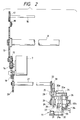
- Fig. 2 is a diagram showing a driving power transmitting system of the recording apparatus
- Fig. 3 is an exploded perspective view showing a pump unit in the apparatus.
- Figs. 4 (a) and 4 (b) are perspective views showing an embodiment of a capping unit to be used in the apparatus as viewed from both sides, respectively;
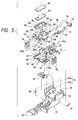
- Fig. 5 is an exploded perspective view showing the embodiment of the capping unit to be used in the apparatus.
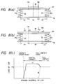
- Figs. 6 (a) to 6 (c) are diagrams illustrative of the size of a slider and a cap frame and of the amounts of displacement caused at the time of capping, respectively;
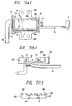
- Figs. 7 (a) to 7 (c) are a top view of an embodiment of a cap holder with a cap attached thereto, a sectional view thereof with the cap removed therefrom; and a sectional view of an embodiment of the cap.
- Fig. 8 (a) is a diagram illustrative of a load to be applied to the cap
- Fig. 8 (b) is a diagram illustrative of a load to be applied when the cap is initially coming into contact with a recording head
- Fig. 8 (c) is a diagram showing a relationship between the distance between the cap and the recording head and the load applied by the cap to the recording head, the relationship being observed between the cap of the invention and a cap that is located on the centerline inside the cap sealing region and that is held by two springs.
- Fig. 9 is a sectional view showing an embodiment of a sheet feed mechanism of a cut sheet feeder.
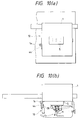
- Figs. 10 (a) and 10 (b) are a plan view and a side view respectively showing a condition in which a carriage is locked by a cleaner unit out of operations of the cleaner unit and the capping unit.
- Fig. 11 (a) and 11 (b) are a plan view and a side view respectively showing a condition in which the carriage is unlocked out of the operations of the cleaner unit and the capping unit.
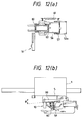
- Figs. 12 (a) and 12 (b) are a plan view and a side view respectively showing a flushing condition out of the operations of the cleaner unit and the capping unit.
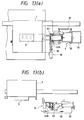
- Figs. 13 (a) and 13 (b) are a plan view and a side view respectively showing a condition in which the cleaner unit is locked out of the operations of the cleaner unit and the capping unit.
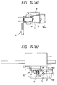
- Figs. 14 (a) and 14 (b) are a plan view and a side view respectively showing a process for causing the carriage to lift the slider out of the operations of the cleaner unit and the capping unit.
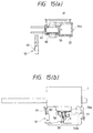
- Figs. 15 (a) and 15 (b) are a plan view and a side view respectively showing a condition in which the recording head is sealed, out of the operations of the cleaner unit and the capping unit.
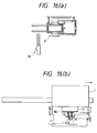
- Figs. 16 (a) and 16 (b) are a plan view and a side view respectively showing an idle sucking condition out of the operations of the cleaner unit and the capping unit.
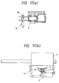
- Figs. 17 (a) and 17 (b) are a plan view and a side view respectively showing a condition in which the cleaner unit has been set ready for cleaning out of the operations of the cleaner unit and the capping unit.
- Figs. 18 (a) and 18 (b) are a plan view and a side view respectively showing a cleaning condition out of the operations of the cleaner unit and the capping unit.
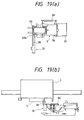
- Figs. 19 (a) and 19 (b) are a plan view and a side view respectively showing a condition in which the cleaner unit has been reset after cleaning out of the operations of the cleaner unit and the capping unit.
- Fig. 20 is a flowchart showing a printing operation of the apparatus
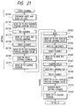
- Fig. 21 is a flowchart showing the first half of the cleaning operation of the apparatus
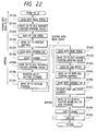
- Fig. 22 is a flowchart showing the latter half of the cleaning operation of the apparatus.
- Fig. 1 is a diagram showing an embodiment of the invention.
- a carriage 1 is connected to a carriage motor 2 through a timing belt 3, and moves to and from across the width of a recording sheet 4.
- the carriage 1 carries an ink jet recording head 5 on the surface thereof confronting the recording sheet 4, the ink jet recording head 5 serving to jet an ink droplet out of a nozzle opening while causing an actuator to apply pressure to ink.
- the carriage 1 has an ink cartridge 6 releasably mounted on the upper surface thereof, the ink cartridge 6 serving to supply the ink to the recording bead 5.
- the recording sheet 4 is forwarded in a direction orthogonal to the carriage 1 moving directions at a predetermined pitch by a forward roller 8 that is connected to a sheet forward motor 7 through a drive force transmission mechanism to be described later.
- a capping unit 9 serving to seal the recording head 5 and a cleaner unit 10.
- the cleaner unit 10 is disposed closer to the printing region than the capping unit 9.
- the capping unit 9 has not only the function of dealing the recording head 5 during nonprinting periods in order to prevent the nozzle openings from clogging, but also the function of forcibly jetting the ink out of the recording head 5 during ink charging periods and during unclogging periods while evacuated to a negative pressure by a pump unit 11. It may be noted that reference numeral 12 denotes a cut sheet feeder.
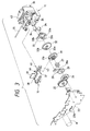
- Fig. 2 and Fig. 3 show an embodiment of the aforementioned drive force transmission mechanism.
- the forward roller 8 has a gear 13 on one end thereof, and is driven while receiving drive force from a pinion 14 on the shaft of the sheet forward motor 7 through an idler 15.
- a sheet feed roller drive shalt 16 has a gear 17 on one end thereof, and transmits motive power to the cut sheet feeder 12 while meshed with the gear 13 through a clutch mechanism 18.
- the pump unit 11 is driven by a gear 22 disposed on one end of a sheet discharge roller 21 while receiving drive force from the pinion 14 of the sheet forward motor 7 through an idler 19 and a sheet discharge roller gear 20.
- the clutch mechanism 18 is normally kept remote from the gears 13, 17 as shown in Fig. 2 by a not shown spring, and has the gears 13, 17 connected thereto when pressed by the carriage 1.
- the pump unit 11 is attached to a home position side surface of a pump frame 23 that is fixed in a direction orthogonal to the carriage 1 travelling directions.
- a gear 26 is rotatably disposed on a shaft 24 of the pump unit 11, the gear 26 being meshable with the gear 22 of the sheet discharge roller 21 through an idler 25.
- the gear 26 has a cleaner cam 29 attached to the back surface thereof so as to be idlably rotatable, the cleaner cam 29 having an arm 28 that frictionally rotates while urged by a spring 27.
- the cleaner cam 29 moves a cleaner unit 10 with the arm 28 thereof.
- Attached to the shaft 24 of the pump unit 11 are a rachet wheel 31, an intermediate transmission wheel 32, and a pump wheel 33, such wheels being placed side by side in such a manner that the intermediate transmission wheel 32 can idlably rotate.
- the rachet wheel 31 has a projection 31a on the surface thereof confronting the intermediate transmission wheel 32.
- the intermediate transmission wheel 32 has projections 32a, 32b on both surfaces thereof, respectively.
- the pump wheel 33 has a projection 33a on the surface thereof confronting the intermediate transmission wheel 32.
- the pump wheel 33 has two shaft holes 33b, 33b, one end of each shaft hole extending toward the center and the other end extending toward the outer circumference. These shaft holes 33b, 33b allow rollers 34, 34 that are journaled thereby to move toward the outer circumference or toward the center in accordance with the rotational directions of the pump wheel 33. That is, by rotating the sheet forward motor 7 either forwardly or reversely, pump operation or release operation can be selected, the pump operation applying pressure to a tube 35 with respect to a pump casing 36 and the release operation not applying pressure to the tube 35.
- the cleaner unit 10 has a groove 38 formed in the upper surface of a cleaner holder 37 so that a cleaning blade 39 is inserted into such groove 38.
- the cleaning blade 39 is high enough to allow the distal end thereof to come in resilient contact with a nozzle plate of the recording head 5.
- the cleaner holder 37 had a guide projection 40 formed on a side portion thereof, and such guide projection 40 is meshed with a guide groove 42 that extends in a direction orthogonal to the carriage 1 moving directions, the guide groove 42 being formed in the upper portion of the pump casing 36.
- the cleaner holder 37 also has a vertically extending elongated hole 43 in a distal end thereof, and such elongated hole 43 is meshed with a projection 28a of the arm 28 of the cleaner cam 29.
- the cleaner holder 37 has a retaining projection 44 formed thereon between the cleaning blade 39 and the guide projection 40, the retaining projection 44 meshing with a carriage stopper 1a disposed on a side surface of the carriage 1.
- the guide projection 40 shuttles along the guide groove 42, so that the cleaner unit 10 is moved from an evacuation position to a cleaning position, i.e., from the right end position to the carriage 1 travelling region as viewed in Fig. 1.
- the cleaning blade 39 comes in resilient contact with the recording head 5, so that the cleaning blade 39 not only wipes the nozzle surface, but also blocks a cap 80 to be described later from moving toward a start end.
- FIG. 4 and Fig. 5 show an embodiment of the capping unit 9.
- a cap frame 51 is attached to the pump frame 23 with two retaining projections 52, 52, which project from one end thereof, meshed with retaining holes 23b, 23b of the pump frame 23, so that the longitudinal direction of the cap frame 51 extends in the carriage 1 travelling directions.
- the cap frame 51 has cam grooves 53, 53 arranged on both sides thereof.
- Each cam groove 53 consisting of an upwardly sloped portion 53a and a horizontal portion 53b, extends from the start end portion side to the termination end portion side of the home position, i.e., from the left to the right as viewed in Fig. 5
- Projections 57 of a slider 56 are slidably attached to these cam grooves 53, 53.
- the slider 56 not only has, on the termination end portion side thereof, a contact piece 56a that comes in contact with the carriage 1, but also has a holder receiving portion formed at a location that is apart from the contact piece 56a by a distance Ls as shown in Fig. 6 (a), the holder receiving portion serving to support the cap 80.
- the distance Ls is equal to a length Lc that is the longitudinal length of the cap 80.
- the slider 56 has, on both sides thereof, guide pieces 56b, 56b that guide the recording head 5.
- the slider 56 also has the termination end portion side thereof supported with the projections 57 thereof attached to the cam grooves 53 of the cap frame 51, and has the start end portion side thereof held by a lever 59 constituting a link that is rotatably urged toward the termination end portion side by a spring 58.
- each projection 57 is formed at a location substantially flush with a sealing surface 80a of the cap 80 ( ⁇ H ⁇ 0).
- the displacement ⁇ L1 can be minimized, ⁇ L1 being the horizontal displacement resulting from the slider 56 rotating about the projections 57 at the time of sealing the recording head 5 after having moved to the capping position.
- the projection 57 is formed at a different location (57'), higher or lower, a larger displacement ⁇ L2 results, thereby making it more difficult to provide reliable sealing.
- the lever 59 that supports the lower portion of the slider 56 is designed as shown in Fig. 6 (b) so that the length of the arm provides a lift ⁇ H1 which is greater than the lift ⁇ H2 provide by the eloped portions 53a of the cam grooves 53. It may be noted that loads to be applied during capping can be reduced by making the sloped portions 53a more horizontal. As a result, by reducing impact to the carriage 1 while reducing the current for driving the carriage motor 2, trouble such as missing dots caused by the recording head 5 breaking the meniscuses is prevented. Therefore, printing reliability can be ensured.
- the length of the lever 59 can be reduced by an amount corresponding to the reduced loads to be applied during capping, so that the horizontal displacement of the slider 56 which is determined by the distance rotated by the lever 59 can be restricted. As a result, the overall size of the capping unit can be reduced.
- the slider 56 meshes with the distal end of the lever 59 through a meshing hole 60 that has a length L and that is formed in the lower portion thereof. That is, the slider 56 is coupled to the lever 59 with a degree of freedom equivalent to the length L of the meshing hole 60 (Fig. 6 (a)), so that the slider 56 can be drawn toward the start end portion side, i.e., the lower end portion side of the sloped portions 53a while maintaining the uncapped condition.
- a stopper surface 63b of the cap holder 63 is displaced to a region confronting the front end face of the cleaner unit 10 by moving the lowest level region of the slider 56 up to such a location as to overlap the cleaner unit 10 operating region, which in turn prevents the cleaner unit 10 from projecting into the carriage 1 moving region.
- the capping unit 9 can be disposed as close to the recording sheet 4 side of the carriage 1 moving path as possible, i.e., without providing a large safety tolerance. Hence, the width of the recording apparatus can be reduced.
- the slider 56 has spring receiving seats 62, 62 formed on the upper surface thereof.
- the spring receiving seats 62, 62 are scattered on left and right sides of the slider 56 so as to be symmetrical about the centerlines extending along the length and across the width of the cap 80, and scattered in the carriage 1 moving direction.
- the slider 56 also has projections 65, 65' formed on both sides of the start and portion side thereof, the projections 66, 65' being meshable with grooves 64, 64' of the cap holder 63.
- the slider 56 has a groove 67 formed along the longitudinal centerline on the termination end portion side thereof, the groove 67 being meshable with a projection 66 of the cap holder 63.
- the cap holder 63 has spring receiving portions 68, 68 that project from both sides thereof. It is in these spring receiving portions 68, 68 that spring receiving seats 69, 69 are arranged so as to be scattered in the carriage 1 moving directions.
- the cap holder 63 also has the grooves 64, 64' formed on both sides of the start end portion side thereof, the grooves 64, 64' being meshable with the projections 65, 65' of the holder 56. Further, the cap holder 63 has the projection 66 formed along the longitudinal centerline on the termination end portion side thereof the projection 66 being meshable with the groove 67 of the slider 56.
- the bottom surface of one of the grooves 64, 64' is slightly higher than that of the other groove 64, 64' or the bottom surface one of the projections 65, 65' is slightly higher than that of the other projection 65, 65'.
- the cap holder 63 is supported at three points so as to allow one side of the start end portion side thereof to take a slightly lower position with respect to the slider 56. Accordingly, the grooves 64, 64' of the cap holder 63 mesh with the projections 65, 65' of the slider 56, with the projection 66 of the cap holder 63 meshed with the groove 67 of the slider 56, end compression springs 70 are interposed between the respective spring receiving portions 62, 69 so that the cap holder 63 is urged upward.
- the cap holder 63 is set so that one side of the cap holder 63 is at least 1mm lower with respect to the slider 56, or one side of the cap holder 63 is inclined with respect to the nozzle surface of the recording head 5 at an angle of 2 degrees or more.
- the cap holder 63 since the cap holder 63 is supported at the three points, the positioning height of the sealing surface of the cap 80 that is accommodated in the cap holder 63 can be adjusted more correctly. Further, the cap 80 can be easily removed from the recording head 5 by applying a peeling force to the cap holder 63 with a point outside the cap 80 as a fulcrum since the moment of the force is large, the cap 80 is easily removed, even when stuck to the recording head 5 due to solidification of the ink or the like. It must be appreciate that the cap holder 63 is resiliently urged toward the recording head 5 by the compression springs 70 which are located to the outside of the sealing region.
- the compression springs 70 having similar elastic properties are used on both sides, and these springs 70 are laid out so as to be symmetrical with respect to the cap 80.
- the cap holder 63 is positioned with one side of the start end portion side being slightly lower than the other side, there is a disequilibrium in the loads to be applied when the cap 80 comes into contact with the recording head 5.
- reaction forces Ra, Rd at the support points A, D are given, respectively, as follows.
- Ra Pa + ⁇ Pa (La - Lb') ⁇ / W' > Pa
- Fig. 8 (c) shows a relationship between the distance between the cap and the recording head and the load to be applied by the cap to the recording head, the relationship being observed between the cap of the invention and a conventional cap that is held by two springs located along a centerline inside the cap sealing region.
- the cap of the invention whose characteristics are indicated by the solid line A can ensure that an adequate load can be given at the initial stage of contact, whereas the conventional cap whose characteristics are indicated by the dashed line B indicates that the full contact load is applied for the first time only immediately before the cap fully contacts the recording head.
- the cap holder 63 has two projections 71 erected along the longitudinal centerline of the bottom surface 63a thereof, and two cylindrical bodies 72, 73 formed on the start end portion side thereof so as to be symmetrical about the longitudinal centerline.
- the cylindrical body 73 is connected to the tube 35 of the pump unit 11 while vertically extended to the outside.
- the cylindrical body 72 is connected to a valve seat 75 (described later) through a tube 74 while extended to the outside, the tube 74 extending in parallel to the bottom surface and bent toward the termination end portion side.
- the tubes 35, 74 are attached to the cap holders 64 at locations which are as close to the longitudinal centerline of the cap 80 as possible and are disposed vertically with respect to the cap and parallel to the moving direction of the cap, the bending moment to be applied to the cap 80 is advantageously reduced as much.
- the valve seat 75 is fixed to the termination end portion of the slider 56, and has a valve 77 fixed thereto.
- An operation rod 79 is attached to the slider 56 not only in such a manner as to be slidable in the carriage moving directions while coming in contact with a contact piece 76 disposed on the cap frame 51, but also at a location confronting the valve 77 so that the valve 77 can maintain the closed position at all times while urged by a spring 78.
- the cap holder 63 holds the cap 80 therein with recesses 81, 82, projections 71, and claws 83 formed in and on the cap 80.
- the cap is made of an elastic member such as rubber having ink resistance.
- the cap 80 has recesses 84, 85 formed in the bottom surface thereof, the recesses 84, 85 communicating with the cylindrical bodies 72, 73, and holds two ink absorbing sheets 86, 87 with claws 83.
- the ink absorbing sheets 86, 87 are made of a porous material having ink resistance.
- Fig. 9 shows an embodiment of the cut sheet feeder 12 in the form of a cut sheet mechanism.
- the cut sheet feeder 12 includes a hopper 90, a separation pad 94, and a sheet feed roller 100.
- the hopper 90 has the lower back surface thereof urged toward the sheet feed roller by a spring 92 that is interposed between a frame 91 and itself. Further, the separation pad 94 that is urged in a normal direction of the sheet feed roller 100 by a spring 93 is disposed on a lower hopper surface confronting the sheet feed roller 100.
- the separation pad 94 is moved up and down by a cam (not shown) so as to be interlocked with the sheet feed operation while the sheet feed roller 100 is making a single revolution, the cam being disposed on the sheet feed roller drive shaft 16.
- the sheet feed roller 100 has an arcuate portion 100a and a straight portion 100b, and is therefore D-shaped in cross section so that a high frictional force can be caused with respect to a recording sheet.
- the sheet feed roller 100 is attached to the sheet feed roller drive shaft 16 through a bushing 101, and makes a single revolution during sheet feed operation while driven by the sheet forward motor 7 through the gear 17.
- the bushing 101 has a cam surface 102 formed thereon so that the cam surface 102 extends around the central shaft excluding a bushing 101 region opposite to the straight portion 100b of the sheet feed roller 100.
- the cam surface 102 allows an idle roller 103 to move therethrough.
- the idle roller 103 is rotatably held by a shaft 105 that is movable within an elongated hole 104 in the frame 91, and is attached so as to be vertically movable with respect to the separation pad 94.
- the sheet feed roller 100 continues to rotate, such uppermost sheet is fed toward the separation pad 94.
- the arcuate portion 100a of the sheet feed roller 100 has passed through the separation pad 94 and the straight portion 100b confronts the separation pad 94. Therefore, it is the idle roller 103 pressed against the cam surface 102 that pushes the recording sheet onto the separation pad 94, which in turn prevents a plurality of unseparated recording sheets from being forwarded to the forward roller 8 superfluously.
- the sheet feed roller 100 makes another revolution, the sheet feed mechanism is reset to the original condition, and therefore ready for next sheet feed operation.
- the carriage 1 is locked with the retaining projection 44 of the cleaner unit 10 by pressing with the carriage stopper 1a as shown in Fig. 10. Therefore, the sheet forward motor 7 is rotated forwardly to thereby evacuate the cleaner unit 10 from the recording head 5 and unlock the carriage as shown in Fig. 11 (S100). As a result, the carriage 1 is movable, so that the carriage 1 is moved slightly toward the start end portion to thereby form a gap _G between the recording head 5 and the cap 80 as shown in Fig. 12 (S101), and a flushing signal is supplied to the recording head 5 under this condition to thereby jet ink droplets onto the cap 80 out of nozzles (S102).
- the cap 80 surface is inclined by an angle ⁇ with respect to the nozzle surface of the recording head 5 under this condition, the possibility that ink splashes bounced back from the ink absorbing sheet 86 will deposit on the nozzle surface is significantly reduced. Since the slight movement of the carriage 1 toward an end of the sheet is contained within the length L of the meshing hole 60 of the lever 59, the lever 59 remains inoperative. Therefore, even if the carriage 1 comes into contact with the slider 56, the resulting shock applied to the carriage 1 is absorbed, which in turn prevents the recording head 5 from damaging the meniscuses and hence ensures reliable printing operations.
- the sheet forward motor 7 rotates forwardly to forward the sheet by a distance equivalent to a single line every time the recording head 5 ends printing a single line of data.
- the pump unit 11 rotates with the rollers 34 which are drawn toward the canter. Therefore, the pump unit 11 does not function as a pump, so that there is no likelihood that the pump unit 11 will apply unnecessary loads to the sheet forward motor 7.
- the slider 56 has moved toward the printing region by a distance equivalent to the length L of the meshing hole 60 of the lever 59 while urged by a return spring 61, so that the stopper surface 63b of the cap holder 63 confronts the cleaner unit 10.
- the cap holder 63 blocks the cleaner unit 10 from plunging into the recording head 5 travelling region. Hence, any situation affecting the recording operation can be prevented.
- the carriage 1 When the recording operation has been brought to an end, the carriage 1 is moved to the home position by the carriage motor 2. During the movement of the carriage 1, the carriage 1 comes into contact with the contact piece 56a of the slider 56 as shown in Fig. 14, so that glider 56 is moved toward the termination end portion against the return spring 61 while rotating the lever 59 against the spring 58. During the movement of the slider 56, the lever 59 is lifted in association with the movement of the carriage 1, and the projections 57 of the slider 56 move along the sloped portions 53a of the cam grooves 53.
- the cap 80 When the slider 56 pushed by the carriage 1 has the projections 57 thereof moved to the horizontal portions 53b of the cam grooves 53, the cap 80 has, first of all, one point on the termination end portion side thereof come in contact with the nozzle surface of the recording head 5 with the compression force of all the compression springs 70 during such movement of the projections 57 along the horizontal portions 53b, because the cap holder 63 is attached to the slider 56 so that one side on the start end portion side of the cap holder 63 takes a slightly lower position.
- the entire circumference of the cap 80 receives the compression force from all the compression springs 70, so that the cap 80 comes in contact with the nozzle surface of the recording head 5 to thereby seal the nozzle surface reliably.
- the projections 57 are substantially flush with the sealing surface 80a of the cap 80 ( ⁇ H ⁇ 0). Therefore, the amount of horizontal displacement _L1 is very small, i.e., the amount of displacement resulting from the slider 56 rotating about the projections 57 at the time of moving to the capping position as shown in Fig. 6 (c), so that the cap 80 can come in contact with the nozzle surface of the recording head 5 reliably, which in turn allows the cap 80 to seal the nozzle surface reliably.
- the stopper surface 63b of the cap holder 63 is evacuated from the cleaner unit 10. Therefore, when the sheet forward motor 7 is rotated reversely, the cleaner cam 29 that has rotated counterclockwise as viewed in Fig. 3 together with the gear 26 causes the cleaner unit 10 to project toward the recording head 5 travelling region by the arm 28 thereof.
- the retaining projection 44 of the cleaner unit 10 gets meshed with the carriage stopper 1a to thereby lock the carriage 1, so that unnecessary movement of the carriage 1 is blocked as shown in Fig. 10.
- the recording head 5 When the recording head 5 has been clogged due to the printing operation and the like performed over a long period of time, the recording head 5 must be cleaned. Not only the sheet forward motor 7 is rotated forwardly from the sealed condition shown in Fig. 10 to thereby discharge the recording sheet, but also the cleaner unit 10 is evacuated from the recording head 5 to thereby unlock the carriage as shown in Fig. 15 (S114). Since the carriage 1 is set movable as a result of such operation, when the carriage 1 is moved further toward the termination end side up to a location shown in Fig. 16 from the capped condition shown in Fig. 15, the operation rod 79 disposed on the slider 56 comes in contact with the contact piece 76 of the cap frame 51 to thereby open the valve 77 of the valve seat 75 to the atmosphere (S115).
- the cleaning blade 39 comes into contact with the nozzle surface of the recording head 5 as shown in Fig. 18. Therefore, by moving the carriage 1 to a wipe end position, the ink deposited on the nozzle surface can be wiped off (S117). Since the cleaning blade 39 is in contact with the cap holder 63 at this time, the ink deposited onto the cleaning blade 39 as a result of the wiping operation is transferred to the cap holder 63 or to the cap 80. Therefore, the amount of ink remaining on the cleaning blade 39 can be kept as small as possible, which in turn ensures reliability in the wiping operation.
- the sheet forward motor 7 Upon completing of the cleaning operation, the sheet forward motor 7 is rotated forwardly in an amount equal to the reverse rotation of the motor 7, so that not only the cleaner unit 10 is returned to the evacuated position again as shown in Fig. 19 (S118), but also the carriage 1 is moved to an idle sucking position to thereby move the slider 56 to the termination end portion and set the recording head 5 ready for idle sucking as shown in Fig. 16 (S119).
- the sheet forward motor 7 is rotated in an amount equivalent to a transmission delay caused by the intermediate transmission wheel 32 (S120), and the carriage 1 is moved slightly toward the start end portion to thereby set the recording head 5 in the sealed condition shown in Fig. 15 (S121).
- the slider 56 moves away from the termination end portion, so that the operation rod 79 on the slider 56 also moves away from the contact piece 76 of the cap frame 51 and hence closes the valve 77 with the urging force of the spring 78.
- the sheet forward motor 7 is rotated reversely to thereby eliminate a transmission delay of the intermediate transmission wheel 32 caused by the last forward rotation of the motor 7 (S127) and to operate the pump unit 11, so that the pump unit 11 sucks the ink remaining in the cap 80 with a strong sucking force without applying sucking force to the recording head 5 (S128).
- the sheet forward motor 7 is rotated forwardly to thereby evacuate the cleaner unit 10 from the recording head 5 travelling path as shown in Fig. 16 (S129). Further, the carriage 1 is moved toward the termination end portion again to thereby allow the cap 80 to seal the recording head 5 in the idle sucking condition as shown in Fig. 16 (S130). Since the cleaner unit 10 has been evacuated from the recording bead 5 travelling path, there is no likelihood that the cleaning blade 39 will come in contact with the nozzle surface of the recording head 5.
- the heat forward motor 7 is rotated reversely to thereby eliminate a transmission delay caused by the intermediate transmission wheel 32 (S131), and the carriage 1 is moved slightly toward the start end portion to thereby set the recording head 5 in the sealed condition shown in Fig. 15 (S132).
- the slider 56 moves away from the termination end portion, so that the valve 77 is closed by the operation rod 79.
- the sheet forward motor 7 is rotated reversely at a low speed, so that such a sucking force as not to cause the ink to be jetted out of the recording head 5 is applied to suck only the ink remaining in the cap 80, and the sucked ink is thereafter discharged into the not shown waste ink tank (S135).
- the cleaner unit 10 is set as shown in Fig. 17 by the low-speed reverse rotation of the sheet forward motor 7 performed in the aforementioned step (S135). Therefore when the carriage 1 is moved to the wipe end position as shown in Fig. 18, wiping operation is performed (S136).
- the sheet forward motor 7 is rotated reversely upon end of the cleaning operation. Since the current reverse rotation of the motor 7 is a succession of the last reverse rotation, the pump unit 11 is operated without having any transmission delay caused by the intermediate transmission wheel 32. As a result, the ink remaining in the cap 80 is sucked at a high negative pressure without applying sucking force to the recording head 5 (S137).
- the sheet forward motor 7 is rotated forwardly in an amount equivalent to a transmission delay caused by the intermediate transmission wheel 32 to thereby evacuate the cleaner unit 10 from the recording head 5 traveling path as shown in Fig. 19 (S138). Further, the carriage 1 is moved toward the termination end portion again to thereby allow the cap 80 to seal the recording head 5 in the idle sucking condition as shown in Fig. 16 (S139).
- the sheet forward motor 7 is rotated reversely to thereby eliminate a transmission delay of the intermediate transmission wheel 32 caused by the last forward rotation of the motor 7 (S140), and the carriage 1 is moved slightly toward the start end portion to thereby set the recording head 5 in the sealed condition shown in Fig. 15 and close the valve 77 (S141).
- the sheet forward motor 7 When the sheet forward motor 7 is rotated reversely at a low speed under this condition, the motive force is transmitted to the pump unit 11 to thereby allow a weak sucking force to be applied to the cap 80. As a result, the ink is forcibly discharged out of the recording head 5 with the weak sucking force, which in turn allows the meniscuses in the nozzles to be recovered (S142).
- the carriage 1 Upon completing the sucking operation, the carriage 1 is moved slightly toward the termination end portion to thereby set the recording head 5 in the idle sucking condition shown in Fig. 16 (S143). Then, the sheet forward motor 7 is rotated reversely at a low speed, so that only the ink remaining in the cap 80 is sucked by such a sucking force as not to cause the ink to be jetted out of the recording head 5 (S144).
- the cleaner unit 10 Upon completing of the idle sucking operation, the cleaner unit 10 has already been set as shown in Fig. 17 by the low-speed reverse rotation of the sheet forward motor 7 performed in the aforementioned step (S144). Therefore, by moving the carriage 1 to the wipe end position shown in Fig. 18, the wiping operation is performed (S145).
- the sheet forward motor 7 is rotated reversely upon completing of the cleaning operation. Since the current reverse rotation of the motor 7 succeeds the last reverse rotation, the pump unit 11 is operated without having any transmission delay caused by the intermediate transmission wheel 32. Therefore, the pump unit 11 sucks the ink remaining in the cap 80 with a strong sucking force with the cap 80 released from the recording head 5, and the ink in the cap 80 is thereafter discharged into the waste ink tank reliably (S146).
- the carriage 1 is moved to the home position to be set in the condition shown in Fig. 15.
- the entire circumference of the cap 80 comes into contact with the nozzle surface of the recording head 5 while receiving the compression force of all the compression springs 70, so that the cap 80 can seal the recording head 5 reliably (S148).
- the sheet forward motor 7 is rotated reversely to thereby mesh the retaining projection 44 of the cleaner unit 10 with the carriage stopper 1a as shown in Fig. 10, so that the carriage 1 is locked to thereby block unnecessary movement thereof (S150).
Priority Applications (2)
| Application Number | Priority Date | Filing Date | Title |
|---|---|---|---|
| EP01123068A EP1167041B1 (en) | 1996-11-22 | 1997-11-24 | Ink jet recording apparatus |
| EP01123069A EP1167042B1 (en) | 1996-11-22 | 1997-11-24 | Ink jet recording apparatus |
Applications Claiming Priority (6)
| Application Number | Priority Date | Filing Date | Title |
|---|---|---|---|
| JP327836/96 | 1996-11-22 | ||
| JP32783696 | 1996-11-22 | ||
| JP32783696 | 1996-11-22 | ||
| JP327837/96 | 1996-11-22 | ||
| JP32783796 | 1996-11-22 | ||
| JP32783796 | 1996-11-22 |
Related Child Applications (2)
| Application Number | Title | Priority Date | Filing Date |
|---|---|---|---|
| EP01123068A Division EP1167041B1 (en) | 1996-11-22 | 1997-11-24 | Ink jet recording apparatus |
| EP01123069A Division EP1167042B1 (en) | 1996-11-22 | 1997-11-24 | Ink jet recording apparatus |
Publications (3)
| Publication Number | Publication Date |
|---|---|
| EP0850773A2 true EP0850773A2 (en) | 1998-07-01 |
| EP0850773A3 EP0850773A3 (en) | 1999-07-21 |
| EP0850773B1 EP0850773B1 (en) | 2003-03-12 |
Family
ID=26572657
Family Applications (3)
| Application Number | Title | Priority Date | Filing Date |
|---|---|---|---|
| EP01123068A Expired - Lifetime EP1167041B1 (en) | 1996-11-22 | 1997-11-24 | Ink jet recording apparatus |
| EP97120574A Expired - Lifetime EP0850773B1 (en) | 1996-11-22 | 1997-11-24 | Ink jet recording apparatus |
| EP01123069A Expired - Lifetime EP1167042B1 (en) | 1996-11-22 | 1997-11-24 | Ink jet recording apparatus |
Family Applications Before (1)
| Application Number | Title | Priority Date | Filing Date |
|---|---|---|---|
| EP01123068A Expired - Lifetime EP1167041B1 (en) | 1996-11-22 | 1997-11-24 | Ink jet recording apparatus |
Family Applications After (1)
| Application Number | Title | Priority Date | Filing Date |
|---|---|---|---|
| EP01123069A Expired - Lifetime EP1167042B1 (en) | 1996-11-22 | 1997-11-24 | Ink jet recording apparatus |
Country Status (3)
| Country | Link |
|---|---|
| US (1) | US6286931B1 (es) |
| EP (3) | EP1167041B1 (es) |
| DE (3) | DE69719709T2 (es) |
Cited By (5)
| Publication number | Priority date | Publication date | Assignee | Title |
|---|---|---|---|---|
| EP1197337A2 (en) * | 2000-09-13 | 2002-04-17 | Canon Kabushiki Kaisha | Improved print head recovery |
| EP1199175A3 (en) * | 2000-10-19 | 2003-01-08 | Canon Kabushiki Kaisha | Liquid eject apparatus and eject recovery method |
| EP1314564A1 (en) * | 2001-11-26 | 2003-05-28 | Seiko Epson Corporation | Head maintenance mechanism for ink jet printer and ink jet printer incorporating the same |
| EP1577095A1 (en) * | 2000-04-06 | 2005-09-21 | Seiko Epson Corporation | Cleaning device and ink-jet printer |
| EP3723993A4 (en) * | 2017-12-14 | 2021-08-04 | Hewlett-Packard Development Company, L.P. | PRINTHEAD LOCK |
Families Citing this family (9)
| Publication number | Priority date | Publication date | Assignee | Title |
|---|---|---|---|---|
| JP2002254666A (ja) * | 2000-09-13 | 2002-09-11 | Seiko Epson Corp | インクジェット式記録装置および同装置における駆動制御方法 |
| JP3827302B2 (ja) * | 2002-06-07 | 2006-09-27 | キヤノン株式会社 | インクジェット記録装置 |
| US20040075728A1 (en) * | 2002-10-21 | 2004-04-22 | Samsung Electronics Co., Ltd | Feeding roller shaft supporter for ink-jet printer |
| KR100561366B1 (ko) * | 2003-01-17 | 2006-03-16 | 삼성전자주식회사 | 잉크젯 프린터의 보전장치 |
| US7857418B2 (en) * | 2006-06-05 | 2010-12-28 | Seiko Epson Corporation | Maintenance sheet and liquid ejecting apparatus |
| AU2007286657B2 (en) | 2006-08-24 | 2012-11-15 | Cook Medical Technologies Llc | Devices and methods for occluding a fistula |
| JP5861474B2 (ja) * | 2012-01-30 | 2016-02-16 | セイコーエプソン株式会社 | ポンプ装置 |
| CN103991289A (zh) * | 2013-02-18 | 2014-08-20 | 星云电脑股份有限公司 | 具收集废墨、清洁与保护喷墨头的印表机喷墨头清洁系统 |
| JP6748371B2 (ja) * | 2015-10-20 | 2020-09-02 | セイコーエプソン株式会社 | 液体吐出装置及び液体吐出装置におけるレール部の調整方法 |
Citations (10)
| Publication number | Priority date | Publication date | Assignee | Title |
|---|---|---|---|---|
| EP0313204A2 (en) * | 1987-10-23 | 1989-04-26 | Hewlett-Packard Company | Service station for ink-jet printer |
| EP0480302A1 (en) * | 1990-10-03 | 1992-04-15 | Canon Kabushiki Kaisha | Ink jet recording apparatus |
| EP0526209A2 (en) * | 1991-07-31 | 1993-02-03 | Canon Kabushiki Kaisha | Drive transmission mechanism for recording apparatus |
| EP0604068A2 (en) * | 1992-12-21 | 1994-06-29 | Hewlett-Packard Company | Printhead servicing apparatus |
| EP0635371A2 (en) * | 1993-07-19 | 1995-01-25 | Hewlett-Packard Company | Tubeless ink-jet printer priming cap and system |
| EP0653306A2 (en) * | 1993-11-11 | 1995-05-17 | OLIVETTI-CANON INDUSTRIALE S.p.A. | Service station for an ink jet printer |
| EP0659571A2 (en) * | 1993-12-27 | 1995-06-28 | Canon Kabushiki Kaisha | Sheet supplying apparatus |
| EP0720912A2 (en) * | 1995-01-04 | 1996-07-10 | Brother International Corporation | Maintenance device in an ink jet printing apparatus |
| EP0724959A1 (en) * | 1995-01-31 | 1996-08-07 | Hewlett-Packard Company | Wet capping system for inkjet printheads |
| EP0744293A1 (en) * | 1995-05-25 | 1996-11-27 | Seiko Epson Corporation | Pump unit and method for using same |
Family Cites Families (3)
| Publication number | Priority date | Publication date | Assignee | Title |
|---|---|---|---|---|
| US4581618A (en) * | 1983-03-09 | 1986-04-08 | Canon Kabushiki Kaisha | Recorder having paper feed mechanism |
| JP3117707B2 (ja) * | 1988-11-22 | 2000-12-18 | 協和醗酵工業株式会社 | 5´―イノシン酸の製造法 |
| JPH09109380A (ja) * | 1995-10-20 | 1997-04-28 | Brother Ind Ltd | インクジェットプリンタ |
-
1997
- 1997-11-24 EP EP01123068A patent/EP1167041B1/en not_active Expired - Lifetime
- 1997-11-24 DE DE69719709T patent/DE69719709T2/de not_active Expired - Lifetime
- 1997-11-24 DE DE69727990T patent/DE69727990T2/de not_active Expired - Lifetime
- 1997-11-24 US US08/977,657 patent/US6286931B1/en not_active Expired - Lifetime
- 1997-11-24 DE DE69725477T patent/DE69725477T2/de not_active Expired - Lifetime
- 1997-11-24 EP EP97120574A patent/EP0850773B1/en not_active Expired - Lifetime
- 1997-11-24 EP EP01123069A patent/EP1167042B1/en not_active Expired - Lifetime
Patent Citations (10)
| Publication number | Priority date | Publication date | Assignee | Title |
|---|---|---|---|---|
| EP0313204A2 (en) * | 1987-10-23 | 1989-04-26 | Hewlett-Packard Company | Service station for ink-jet printer |
| EP0480302A1 (en) * | 1990-10-03 | 1992-04-15 | Canon Kabushiki Kaisha | Ink jet recording apparatus |
| EP0526209A2 (en) * | 1991-07-31 | 1993-02-03 | Canon Kabushiki Kaisha | Drive transmission mechanism for recording apparatus |
| EP0604068A2 (en) * | 1992-12-21 | 1994-06-29 | Hewlett-Packard Company | Printhead servicing apparatus |
| EP0635371A2 (en) * | 1993-07-19 | 1995-01-25 | Hewlett-Packard Company | Tubeless ink-jet printer priming cap and system |
| EP0653306A2 (en) * | 1993-11-11 | 1995-05-17 | OLIVETTI-CANON INDUSTRIALE S.p.A. | Service station for an ink jet printer |
| EP0659571A2 (en) * | 1993-12-27 | 1995-06-28 | Canon Kabushiki Kaisha | Sheet supplying apparatus |
| EP0720912A2 (en) * | 1995-01-04 | 1996-07-10 | Brother International Corporation | Maintenance device in an ink jet printing apparatus |
| EP0724959A1 (en) * | 1995-01-31 | 1996-08-07 | Hewlett-Packard Company | Wet capping system for inkjet printheads |
| EP0744293A1 (en) * | 1995-05-25 | 1996-11-27 | Seiko Epson Corporation | Pump unit and method for using same |
Cited By (11)
| Publication number | Priority date | Publication date | Assignee | Title |
|---|---|---|---|---|
| EP1577095A1 (en) * | 2000-04-06 | 2005-09-21 | Seiko Epson Corporation | Cleaning device and ink-jet printer |
| EP1197337A2 (en) * | 2000-09-13 | 2002-04-17 | Canon Kabushiki Kaisha | Improved print head recovery |
| EP1197337A3 (en) * | 2000-09-13 | 2002-06-12 | Canon Kabushiki Kaisha | Improved print head recovery |
| US7052106B1 (en) | 2000-09-13 | 2006-05-30 | Canon Kabushiki Kaisha | Print head recovery |
| EP1199175A3 (en) * | 2000-10-19 | 2003-01-08 | Canon Kabushiki Kaisha | Liquid eject apparatus and eject recovery method |
| US6619781B2 (en) | 2000-10-19 | 2003-09-16 | Canon Kabushiki Kaisha | Liquid eject apparatus and eject recovery method |
| EP1314564A1 (en) * | 2001-11-26 | 2003-05-28 | Seiko Epson Corporation | Head maintenance mechanism for ink jet printer and ink jet printer incorporating the same |
| US6746098B2 (en) | 2001-11-26 | 2004-06-08 | Seiko Epson Corporation | Head maintenance mechanism for ink jet printer and ink jet printer incorporating the same |
| US6994418B2 (en) | 2001-11-26 | 2006-02-07 | Seiko Epson Corporation | Head maintenance mechanism for ink jet printer and ink jet printer incorporating the same |
| EP3723993A4 (en) * | 2017-12-14 | 2021-08-04 | Hewlett-Packard Development Company, L.P. | PRINTHEAD LOCK |
| US11260665B2 (en) | 2017-12-14 | 2022-03-01 | Hewlett-Packard Development Company, L.P. | Print head lock |
Also Published As
| Publication number | Publication date |
|---|---|
| DE69725477D1 (de) | 2003-11-13 |
| US6286931B1 (en) | 2001-09-11 |
| DE69725477T2 (de) | 2004-07-29 |
| EP1167042A1 (en) | 2002-01-02 |
| EP0850773B1 (en) | 2003-03-12 |
| EP0850773A3 (en) | 1999-07-21 |
| EP1167041A1 (en) | 2002-01-02 |
| EP1167042B1 (en) | 2003-10-08 |
| DE69719709D1 (de) | 2003-04-17 |
| DE69727990D1 (de) | 2004-04-08 |
| EP1167041B1 (en) | 2004-03-03 |
| DE69719709T2 (de) | 2004-02-05 |
| DE69727990T2 (de) | 2004-07-22 |
Similar Documents
| Publication | Publication Date | Title |
|---|---|---|
| EP1369242B1 (en) | Ink jet recording apparatus and cleaning portion of such recording apparatus | |
| EP0597505B1 (en) | Recording apparatus | |
| EP1167041B1 (en) | Ink jet recording apparatus | |
| EP0526209B1 (en) | Drive transmission mechanism for recording apparatus | |
| EP0720912B1 (en) | Maintenance device in an ink jet printing apparatus | |
| EP0916508B1 (en) | Ink jet recording apparatus | |
| US8152270B2 (en) | Inkjet recording apparatus | |
| JP2002307698A (ja) | ヘッド吐出特性維持装置及びそれを備えたインクジェット式プリンタ | |
| EP1040924B1 (en) | Ink jet recording apparatus | |
| US5963229A (en) | Ink jet recording apparatus having ink absorbing member for absorbing ink from an ink wiping member | |
| JP3712222B2 (ja) | インクジェット式記録装置 | |
| US6568788B2 (en) | Ink jet recording apparatus | |
| US5917517A (en) | Ink jet recording apparatus and wiping method used for such apparatus | |
| JP3573207B2 (ja) | インクジェット式記録装置 | |
| JP3712221B2 (ja) | インクジェット式記録装置 | |
| JP4174273B2 (ja) | インクジェット記録装置 | |
| JPH10202894A (ja) | インクジェット式記録装置 | |
| JPH11138831A (ja) | インクジェット記録装置の回復系 | |
| JP2004122619A (ja) | クリーニング機構部及びインクジェット記録装置 | |
| JP2006326982A (ja) | インクジェット記録装置 | |
| JP2003080719A (ja) | インクジェット記録装置 | |
| JPH10258516A (ja) | インクジェット記録装置 | |
| JPH1024566A (ja) | シート材排出装置及び記録装置 | |
| JP2003205637A (ja) | インクジェット式記録装置および同装置における記録ヘッドのメンテナンス制御方法 |
Legal Events
| Date | Code | Title | Description |
|---|---|---|---|
| PUAI | Public reference made under article 153(3) epc to a published international application that has entered the european phase |
Free format text: ORIGINAL CODE: 0009012 |
|
| AK | Designated contracting states |
Kind code of ref document: A2 Designated state(s): DE FR GB IT |
|
| AX | Request for extension of the european patent |
Free format text: AL;LT;LV;MK;RO;SI |
|
| 17P | Request for examination filed |
Effective date: 19980715 |
|
| PUAL | Search report despatched |
Free format text: ORIGINAL CODE: 0009013 |
|
| AK | Designated contracting states |
Kind code of ref document: A3 Designated state(s): AT BE CH DE DK ES FI FR GB GR IE IT LI LU MC NL PT SE |
|
| AX | Request for extension of the european patent |
Free format text: AL;LT;LV;MK;RO;SI |
|
| AKX | Designation fees paid |
Free format text: DE FR GB IT |
|
| 17Q | First examination report despatched |
Effective date: 20010409 |
|
| GRAG | Despatch of communication of intention to grant |
Free format text: ORIGINAL CODE: EPIDOS AGRA |
|
| GRAG | Despatch of communication of intention to grant |
Free format text: ORIGINAL CODE: EPIDOS AGRA |
|
| GRAH | Despatch of communication of intention to grant a patent |
Free format text: ORIGINAL CODE: EPIDOS IGRA |
|
| GRAH | Despatch of communication of intention to grant a patent |
Free format text: ORIGINAL CODE: EPIDOS IGRA |
|
| GRAA | (expected) grant |
Free format text: ORIGINAL CODE: 0009210 |
|
| AK | Designated contracting states |
Designated state(s): DE FR GB IT |
|
| REG | Reference to a national code |
Ref country code: GB Ref legal event code: FG4D |
|
| REF | Corresponds to: |
Ref document number: 69719709 Country of ref document: DE Date of ref document: 20030417 Kind code of ref document: P |
|
| ET | Fr: translation filed | ||
| PLBE | No opposition filed within time limit |
Free format text: ORIGINAL CODE: 0009261 |
|
| STAA | Information on the status of an ep patent application or granted ep patent |
Free format text: STATUS: NO OPPOSITION FILED WITHIN TIME LIMIT |
|
| 26N | No opposition filed |
Effective date: 20031215 |
|
| PGFP | Annual fee paid to national office [announced via postgrant information from national office to epo] |
Ref country code: IT Payment date: 20101113 Year of fee payment: 14 |
|
| PG25 | Lapsed in a contracting state [announced via postgrant information from national office to epo] |
Ref country code: IT Free format text: LAPSE BECAUSE OF NON-PAYMENT OF DUE FEES Effective date: 20121124 |
|
| REG | Reference to a national code |
Ref country code: FR Ref legal event code: PLFP Year of fee payment: 19 |
|
| PGFP | Annual fee paid to national office [announced via postgrant information from national office to epo] |
Ref country code: GB Payment date: 20151118 Year of fee payment: 19 Ref country code: DE Payment date: 20151118 Year of fee payment: 19 |
|
| PGFP | Annual fee paid to national office [announced via postgrant information from national office to epo] |
Ref country code: FR Payment date: 20151008 Year of fee payment: 19 |
|
| REG | Reference to a national code |
Ref country code: DE Ref legal event code: R119 Ref document number: 69719709 Country of ref document: DE |
|
| GBPC | Gb: european patent ceased through non-payment of renewal fee |
Effective date: 20161124 |
|
| REG | Reference to a national code |
Ref country code: FR Ref legal event code: ST Effective date: 20170731 |
|
| PG25 | Lapsed in a contracting state [announced via postgrant information from national office to epo] |
Ref country code: FR Free format text: LAPSE BECAUSE OF NON-PAYMENT OF DUE FEES Effective date: 20161130 |
|
| PG25 | Lapsed in a contracting state [announced via postgrant information from national office to epo] |
Ref country code: DE Free format text: LAPSE BECAUSE OF NON-PAYMENT OF DUE FEES Effective date: 20170601 Ref country code: GB Free format text: LAPSE BECAUSE OF NON-PAYMENT OF DUE FEES Effective date: 20161124 |