BACKGROUND OF THE INVENTION
Field of the Invention
The present invention relates to an image pickup
apparatus capable of inputting an image of substantially
high image quality by finely varying the optical angle of a
parallel-plane plate glass or a reflecting mirror which is
provided in the optical path of an image pickup system.
Description of Related Art
In recent years, image input apparatus such as
video cameras and scanners have made remarkable advances,
and far higher image quality and far higher resolution have
been strongly demanded. However, to increase the number of
pixels per image pickup element involves a number of
problems, such as performance problems such as a lowering in
sensitivity or S/N, an increase in cost due to a decrease in
production yield, and the necessity for an expensive quartz-crystal
low-pass filter or the like for preventing a false
signal or the like.
What is called "pixel shifting" is known as a
method of increasing the image quality and the resolution of
an image pickup apparatus without increasing the number of
pixels per image pickup element. The pixel shifting is a
method of finely vibrating an image pickup element itself or
sequentially obtaining optical-video information by
conducting, to photosensitive portions on the image pickup
element, optical-image information which would have reached
non-photosensitive portions between adjacent photosensitive
portions, while varying the reflection angle of a reflecting
mirror disposed in an optical path in an optical relay space
between a lens group and the image pickup element or while
varying the incident angle of light on an optical
transmission glass having the shape of a parallel-plane
plate or varying the thickness of the optical transmission
glass by using the refraction of light by the optical
transmission glass which is disposed in such optical path.
According to such pixel shifting, it is possible to obtain
an image having a high resolution which is substantially
equivalent to a resolution obtainable when the number of
pixels of an image pickup element is increased.
Since this method makes it possible to pick up an
image of high image quality without increasing the number of
pixels of the image pickup element itself, the pixel
shifting is a method which is extremely effective in
increasing the resolution of the image input apparatus.
Specific examples of pixel shifting using the
above-described principles have been disclosed. For
example, Japanese Laid-Open Patent Application No. Sho 59-15378
discloses the art of rotating a parallel-plane plate
about an axis parallel to a pixel array, Japanese Laid-Open
Patent Application No. Hei 1-121816 discloses the art of
inclining a parallel-plane plate surface and rotating it
about an optical axis, and Japanese Laid-Open Utility Model
Application No. Hei 6-8937 discloses the art of driving a
cam mechanism by means of a motor and varying the
inclination of a parallel-plane plate surface in the
directions of X and Y axes.
However, in any of the above-described
conventional mechanism examples which use a parallel-plane
plate optical-transmission glass, a motor is used as a drive
source which varies the optical position of the parallel-plane
plate optical-transmission glass and a complicated
expensive mechanism such as a position control mechanism
using a cam, with the result that it is difficult to ensure
the positioning accuracy of the parallel-plane plate
optical-transmission glass and it is also difficult to
increase the driving speed thereof.
If two horizontal and vertical systems each
including a motor, a cam and a mechanism for transmitting
the drive force of the motor are incorporated in an image
pickup apparatus, a number of problem will occur; for
example, the entire pixel shifting mechanism necessarily
become larger in size and difficult to dispose in the space
between the lens group and the image pickup element.
BRIEF SUMMARY OF THE INVENTION
The present invention has been made to solve the
above-described problems, and its first object is to provide
a pixel shifting method, an optical (pixel shifting)
apparatus and an image pickup apparatus all of which are
capable of realizing high-speed driving by using a simple
arrangement.
A second object of the present invention is to
provide a pixel shifting method and an optical (pixel
shifting) apparatus both of which are capable of realizing
pixel shifting of multiple steps and control of the amount
of pixel shifting by using an extremely simple arrangement
without the need for a complicated arrangement.
A third object of the present invention is to
provide an optical apparatus which enables pixel shifting
which is easy to control and can be driven at extremely high
speed without the need for a complicated mechanism.
To achieve the above objects, in accordance with
one aspect of the present invention, there is provided an
optical apparatus which comprises an optical element for
shifting a position of an incident light beam on an image
forming plane, a plurality of restricting portions for
controlling an inclination position of the optical element
with respect to an optical axis by respectively restricting
end portions of the optical element, and driving means for
driving the optical element to the restricting portions.
To achieve the above objects, in accordance with
another aspect of the present invention, there is provided
an optical apparatus which has position restricting surfaces
formed before and behind each end portion of an optical
element in the direction of the optical axis and determines
the inclination angle of the optical element relative to the
optical axis by restricting the position of each end portion
of the optical element in the direction of the optical axis
by means of the position restricting surfaces, the optical
element being capable of being controlled to move among a
plurality of inclination angles, by modifying a combination
of the position restricting surfaces which the end portions
of the optical element selectively come into abutment with.
In accordance with another aspect of the present
invention, there is provided an optical apparatus in which a
drive source for driving a parallel-plane plate disposed in
an image pickup optical system includes a plurality of
electromagnets and is arranged to vary the inclination
position of the optical element by performing on-off control
of each of the electromagnets to select the position
restricting surfaces which the optical element comes into
abutment with.
In accordance with another aspect of the present
invention, there is provided an optical apparatus which is
provided with a plurality of optical elements and a
plurality of restricting portions and is arranged to
determine an entire amount of image shifting by combining
the amounts of image shifting of a light beam according to
the respective inclination positions of the plurality of
optical elements.
A fourth object of the present invention is to
integrate a pixel shifting mechanism with an optical
apparatus as one unit and improve the applicability of the
pixel shifting mechanism to various lens units and cameras
as well as the versatility of the pixel shifting mechanism.
A fifth object of the present invention is to
provide a lens unit in which a pixel shifting mechanism is
incorporated.
The above and other objects, features and
advantages of the present invention will become apparent
from the following detailed description of preferred
embodiments of the present invention, taken in conjunction
with the accompanying drawings, the description being
given by way of example only.
BRIEF DESCRIPTION OF THE SEVERAL VIEWS OF THE DRAWING
Figs. 1(a) and 1(b) are diagrammatic perspective
views aiding in explaining the arrangement and the operation
principle of a pixel shifting system according to a first
embodiment of the present invention;
Figs. 2(a) and 2(b) are diagrammatic views aiding
in explaining the arrangement and the operation principle of
the pixel shifting system according to the first embodiment
of the present invention;
Figs. 3(a) and 3(b) are diagrammatic views aiding
in explaining the arrangement and the operation principle of
the pixel shifting system according to the first embodiment
of the present invention;
Fig. 4 is a diagrammatic view aiding in explaining
the vertical pixel shifting operation of the pixel shifting
system according to the first embodiment of the present
invention;
Fig. 5 is a diagrammatic view aiding in explaining
the vertical pixel shifting operation of the pixel shifting
system according to the first embodiment of the present
invention;
Fig. 6 is a diagrammatic view aiding in explaining
the vertical pixel shifting operation of the pixel shifting
system according to the first embodiment of the present
invention;
Fig. 7 is a diagrammatic view aiding in explaining
the vertical pixel shifting operation of the pixel shifting
system according to the first embodiment of the present
invention;
Fig. 8 is a diagrammatic view aiding in explaining
the horizontal pixel shifting operation of the pixel
shifting system according to the first embodiment of the
present invention;
Fig. 9 is a diagrammatic view aiding in explaining
the horizontal pixel shifting operation of the pixel
shifting system according to the first embodiment of the
present invention;
Fig. 10 is a diagrammatic view aiding in
explaining the horizontal pixel shifting operation of the
pixel shifting system according to the first embodiment of
the present invention;
Fig. 11 is a diagrammatic view aiding in
explaining the horizontal pixel shifting operation of the
pixel shifting system according to the first embodiment of
the present invention;
Figs. 12(a) and 12(b) are views aiding in
explaining the combined pixel shifting operation of the
pixel shifting system according to the first embodiment of
the present invention;
Fig. 13 is a diagrammatic view aiding in
explaining the vertical pixel shifting operation of a pixel
shifting system according to a second embodiment of the
present invention;
Fig. 14 is a diagrammatic view aiding in
explaining the vertical pixel shifting operation of the
pixel shifting system according to the second embodiment of
the present invention;
Fig. 15 is a diagrammatic view aiding in
explaining the vertical pixel shifting operation of the
pixel shifting system according to the second embodiment of
the present invention;
Fig. 16 is a diagrammatic view aiding in
explaining the vertical pixel shifting operation of the
pixel shifting system according to the second embodiment of
the present invention;
Fig. 17 is a diagrammatic view aiding in
explaining the horizontal pixel shifting operation of the
pixel shifting system according to the second embodiment of
the present invention;
Fig. 18 is a diagrammatic view aiding in
explaining the horizontal pixel shifting operation of the
pixel shifting system according to the second embodiment of
the present invention;
Fig. 19 is a diagrammatic view aiding in
explaining the horizontal pixel shifting operation of the
pixel shifting system according to the second embodiment of
the present invention;
Fig. 20 is a diagrammatic view aiding in
explaining the horizontal pixel shifting operation of the
pixel shifting system according to the second embodiment of
the present invention;
Fig. 21 is a diagrammatic view showing the
operation of the second embodiment of the present invention;
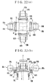
Figs. 22(a) and 22(b) are diagrammatic views
showing the arrangement of a third embodiment of the present
invention;
Figs. 23(a) and 23(b) are exploded perspective
views showing an arrangement in which a pixel shifting
system according to any of the embodiments of the present
invention is incorporated as a unit;
Fig. 24 is a diagrammatic cross-sectional view
showing an arrangement in which the unit of a pixel shifting
mechanism according to any of the embodiments of the present
invention is actually incorporated into a camera;
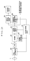
Fig. 25 is a block diagram showing a circuit
arrangement for picking up an image by using the pixel
shifting system according to any of the embodiments of the
present invention; and
Figs. 26(a) and 26(b) are views showing the
principle of pixel shifting.
DETAILED DESCRIPTION OF THE INVENTION
Preferred embodiments of the image pickup
apparatus according to the present invention will be
described below.
First of all, description will be made in
connection with the operation principle of "pixel shifting"
which makes it possible to pickup up an image of high image
quality by shifting the incident position of light incident
on a image pickup surface of an image pickup element, on a
pixel-by-pixel basis on the image pickup surface.
The principle of optical-path shifting which uses
refraction of light by a parallel-plane plate optical
transmission glass will be described below with reference to
Figs. 26(a) and 26(b). Fig. 26(a) shows a state before an
optical path is shifted, while Fig. 26(b) shows a state
after the optical path is shifted.
In Figs. 26(a) and 26(b), reference numeral 100
denotes a subject such as a document an image of which to be
picked up, reference numeral 102 denotes an image pickup
lens group, and reference numeral 103 denotes an optical
element made of an optically transmissive substance. The
optical element 103 is disposed so that it can incline with
respect to the optical axis of the optical system, and is
shaped like a parallel-plane plate having a uniform
refractive index and serves as light-beam moving means.
Reference numeral 104 denotes a solid-state image pickup
element such as a CCD which serves as image pickup means for
photoelectrically converting a light image of the subject
100 focused by the lens group 102 and outputting the
obtained picked-up image signal.
As shown in Fig. 26(a), light from a point 101a on
the subject 100 passes through the lens group 102 and the
optical element 103 and is made incident on a photosensitive
portion 104a of the solid-state image pickup element 104, so
that the incident light is photoelectrically converted into
valid data.
On the other hand, light from a point 101b on the
subject 100 passes through the lens group 102 and the
optical element 103 and is made incident on a non-photosensitive
portion 104b between adjacent photosensitive
portions of the solid-state image pickup element 104, but
the incident light is not photoelectrically converted and is
wasted as invalid data.
Letting δ1 be the amount of deviation of light
between the direction in which the light enters the optical
element 103 and the refraction direction in which the light
exits from the optical element 103, letting 1 be the angle
made by the entering light and the normal to the entrance
surface of the optical element 103, letting t be the
thickness of the optical element 103, and letting N be the
refractive index of the optical element 103, the following
equation is obtained:
δ1 = (1 - 1/N) · t · 1.
The angle made by the optical element 103 and the
image pickup surface of the solid-state image pickup element
104 at this time is denoted by ω1 for convenience' sake.
Fig. 26(b) shows a state in which the inclination
of the optical element 103 is varied by ω = (ω2 - ω1).
In Fig. 26(b), letting δ2 be the amount of
deviation of light between the direction in which the light
enters the optical element 103 and the refraction direction
in which the light exits from the optical element 103, and
letting 2 be the angle made by the entering light and the
normal to the entrance surface of the optical element 103,
the following equation is obtained:
δ2 = (1 - 1/N) · t · 2,
where t is the thickness of the optical element 103 and N is
the refractive index of the optical element 103.
Here, a deviation δ of the light which exits from
the optical element 103 toward the solid-state image pickup
element 104 when the optical system changes from the state
of Fig. 26(a) to the state of Fig. 26(b) is expressed as
follows:
δ = δ1 + δ2
= (1 - 1/N) · t · (1 + 2)
= (1 - 1/N) · t · (ω2 - ω1),
so that
δ = (1 - 1/N) · t · ω.
During the state of Fig. 26(a), the light
information from the point 101b on the subject 100 is made
incident on the non-photosensitive portion 104b on the
solid-state image pickup element 104 and is wasted as
invalid data. However, if the state of Fig. 26(a) is
changed to the state of Fig. 26(b), it is possible to make
the light information from the point 101b incident on a
photosensitive portion 104c of the solid-state image pickup
element 104, so that the light information can be used as
valid data.
If the picked-up image data obtained in the state
of Fig. 26(a) and the picked-up image data obtained in the
state of Fig. 26(b) are stored in a memory and the stored
data are combined after phase-corrected, it is possible to
obtain the amount of data which is equivalent to twice the
number of pixels of the solid-state image pickup element
104.
On the basis of the above-described principle, if
the optical element 103 is made stationary at several
inclination positions and light information received by the
solid-state image pickup element 104 for each of the
inclination positions is stored in the memory, it is
possible to obtain image information the amount of which is
equivalent to several times the number of photosensitive
portions of the solid-state image pickup element 104.
The fundamental principle of "pixel shifting"
itself is as described above, and preferred embodiments of
the present invention will be described below.
(First Embodiment)
A first embodiment of the present invention
comprises a horizontal shifting mechanism and a vertical
shifting mechanism both of which are provided between an
image pickup lens and an image pickup element (CCD), and the
horizontal shifting mechanism includes a parallel-plane
plate glass for shifting a light beam entering from the
image pickup lens, in a horizontal direction on an image
pickup surface of the image pickup element, whereas the
vertical shifting mechanism includes a parallel-plane plate
glass for shifting such light beam in a vertical direction
on the image pickup surface of the image pickup element.
Figs. 1(a) and 1(b) are diagrammatic perspective
views showing the arrangement of a pixel shifting system in
an image pickup apparatus according to the first embodiment
of the present invention. In Figs. 1(a) and 1(b), an image
pickup lens unit 1 constitutes an optical system, and an
image pickup element 2 such as a CCD constitutes image
pickup means. A transmission parallel-plane plate glass 3
(hereinafter referred to as the parallel-plane plate 3) is
made of glass or plastics and constitutes a (vertical)
optical element for vertically shifting a light beam passing
through the image pickup lens unit 1 on an image pickup
surface (image forming surface) of the image pickup element
2. Armatures 4U and 4D of electromagnetic soft iron, each
of which constitutes an engagement part, are respectively
disposed at the opposite ends of the parallel-plane plate 3,
and electromagnets 5Ua and 5Ub; 5Da and 5Db which constitute
driving means (electromagnetic driving means) for driving
such optical element are respectively disposed before and
behind the armatures 4U and 4D in the direction of the
optical axis. The incident position of the light beam on
the image pickup surface can be vertically shifted up or
down by controlling the driving states of the respective
electromagnets 5Ua, 5Ub, 5Da and 5Db to control the state of
inclination of the parallel-plane plate 3 and rotate the
parallel-plane plate 3 in either of the directions indicated
by a double-headed arrow V.
The electromagnet 5Ua is composed of a yoke 51U
and a coil 53U, and the electromagnet 5Ub is composed of a
yoke 52U and a coil 54U. The electromagnets 5Ua and 5Ub
constitute (electromagnetic) driving means for moving the
armature 4U back and forth in accordance with the control of
supply of electricity to the respective coils 53U and 54U of
the electromagnets 5Ua and 5Ub.
The electromagnet 5Da is composed of a yoke 51D
and a coil 53D, and the electromagnet 5Db is composed of a
yoke 52D and a coil 54D. The electromagnets 5Da and 5Db
constitute (electromagnetic) driving means for moving the
armature 4D back and forth in accordance with the control of
supply of electricity to the respective coils 53D and 54D of
the electromagnets 5Da and 5Db.
If the inclination angle of the parallel-plane
plate 3 is varied by moving the top and bottom portions of
the parallel-plane plate 3 back and forth in the direction
of the optical axis by on-off control of the electromagnets
5Ua and 5Ub; 5Da and 5Db, the incident position of the light
beam, which has passed through the parallel-plane plate 3,
on the image pickup surface of the image pickup element 2
can be shifted vertically (up or down) with respect to the
direction of the optical axis.
A parallel-plane plate glass 6 (hereinafter
referred to as the parallel-plane plate 6) is provided for
horizontally shifting a light beam passing through the image
pickup lens unit 1 on the image pickup surface. Armatures
7L and 7R of electromagnetic soft iron, each of which
constitutes an engagement part, are respectively disposed at
the opposite ends of the parallel-plane plate 6, and
electromagnets 8La and 8Lb; 8Ra and 8Rb are respectively
disposed before and behind the armatures 7L and 7R in the
direction of the optical axis. The incident position of the
light beam on the image pickup surface can be horizontally
shifted toward the right or the left by controlling the
driving states of the respective electromagnets 8La, 8Lb,
8Ra and 8Rb to control the state of inclination of the
parallel-plane plate 6 and rotate the parallel-plane plate 6
in either of the directions indicated by a double-headed
arrow H.
The electromagnet 8La is composed of a yoke 81L
and a coil 83L, and the electromagnet 8Lb is composed of a
yoke 82L and a coil 84L. The electromagnets 8La and 8Lb
constitute (electromagnetic) driving means for moving the
armature 7L provided at the left end of the parallel-plane
plate 6, back and forth in accordance with the control of
supply of electricity to the respective coils 83L and 84L of
the electromagnets 8La and 8Lb.
The electromagnet 8Ra is composed of a yoke 81R
and a coil 83R, and the electromagnet 8Rb is composed of a
yoke 82R and a coil 84R. The electromagnets 8Ra and 8Rb
constitute (electromagnetic) driving means for moving the
armature 7R provided at the right end of the parallel-plane
plate 6, back and forth in accordance with the control of
supply of electricity to the respective coils 83R and 84R of
the electromagnets 8Ra and 8Rb.
If the inclination angle of the parallel-plane
plate 6 is varied by moving the right and left portions of
the parallel-plane plate 6 back and forth in the direction
of the optical axis by on-off control of the electromagnets
8Ra and 8Rb; 8La and 8Lb, the incident position of the light
beam, which has passed through the parallel-plane plate 6,
on the image pickup surface of the image pickup element 2
can be shifted horizontally (toward the right or the left)
with respect to the direction of the optical axis.
The two vertical and horizontal parallel- plane
plates 3 and 6 are disposed in the space between the image
pickup lens unit 1 and the image pickup element 2 in such a
manner that the respective parallel- plane plates 3 and 6 are
made to incline with respect to the vertical and horizontal
directions, thereby shifting the position of incidence on
the image pickup surface of the light beam which has passed
through the image pickup lens unit 1, in the vertical and
horizontal directions at a pitch smaller than the pixel-to-pixel
distance of the image pickup element 2. Accordingly,
the image pickup apparatus can pick up an image which is
incident on the image pickup surface at a location between
each pixel of the image pickup element 2, so that the image
pickup apparatus is capable of realizing an image quality
equivalent to that of an image picked up by an image pickup
element, the number of pixels of which is greater than the
actual number of pixels of the image pickup element 2.
The detailed arrangement and the operation of the
pixel shifting system according to the first embodiment of
the present invention will be described below with reference
to Figs. 2(a), 2(b) to 6.
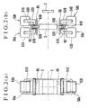
Figs. 2(a) and 2(b) show the arrangement of the
parallel-plane plate 3 which performs vertical pixel
shifting.
The pixel shifting system according to the first
embodiment of the present invention is disposed between the
image pickup lens unit 1 and the image pickup element 2. In
practice, the pixel shifting system may be disposed, for
example, in the lens unit of a camera or in the camera body
thereof.
Fig. 2(a) shows the state of the parallel-plane
plate 3 as viewed from the front side, i.e., in the
direction of incidence of a light beam, while Fig. 2(b)
shows the state of the parallel-plane plate 3 as viewed from
the right side. As shown in Fig. 2(a), the parallel-plane
plate 3 is positioned in front of the image pickup surface
of the image pickup element 2, and has a size which covers
the entire image pickup surface.
The top and bottom armatures 4U and 4D of the
parallel-plane plate 3 are located in a frame portion of the
lens unit or a frame portion of the camera body.
As shown in Fig. 2(b), the parallel-plane plate 3
is held in the state in which the armatures 4U and 4D of
electromagnetic soft iron provided at the opposite ends of
the parallel-plane plate 3 are respectively movably fitted
in recesses 91U and 91D formed in the frame portion, i.e.,
in the state of having predetermined clearances in the
forward and rearward directions and in the upward and
downward directions.
Each of the recesses 91U and 91D is extended by a
length approximately equal to the width of the parallel-plane
plate 3 in a direction perpendicular to the surface of
the sheet of Fig. 2(b), and the armatures 4U and 4D of
electromagnetic soft iron provided at the opposite ends of
the parallel-plane plate 3 are formed into cylindrical
shapes which respectively extend along inner surfaces 92U
and 93U of the recess 91U and inner surfaces 92D and 93D of
the recess 91D. Accordingly, the armatures 4U and 4D can
come into line contact with restriction surfaces in the
respective recesses 91U and 91D so that the inclination of
the parallel-plane plate 3 with respect to the rolling
direction can be restricted. As another method for
obtaining the same effect as the line contact due to the
cylindrical shape, a plurality of point contact portions may
be formed on the line of the line contact.
These recesses function as restriction portions
for positioning the optical element of the present
invention, and the surfaces which come into abutment with
the armatures which constitute the engagement parts of the
parallel-plane plate serving as the optical element function
as position restricting surfaces or position restricting
portions for positioning.
By bringing the armature 4U into abutment with
either of the inner surfaces 92U and 93U which are
respectively arranged in the recess 91U along the optical
axis, i.e., located on the left and right sides as viewed in
Fig. 2(b), and by bringing the armature 4D into abutment
with either of the inner surfaces 92D and 93D which are
respectively arranged in the recess 91D along the optical
axis, i.e., located on the left and right sides as viewed in
Fig. 2(b), the inclination position of the parallel-plane
plate 3 with respect to the optical axis and the position of
the parallel-plane plate 3 in the direction of the optical
axis are determined, and the respective amounts of movements
along the optical axis of the armatures 4U and 4D provided
at the opposite ends of the parallel-plane plate 3 are
determined according to the respective widths of the
recesses 91U and 91D which are taken in the direction of the
optical axis. In consequence, the parallel-plane plate 3 is
controlled so that the amount of inclination of the
parallel-plane plate 3 or the position thereof in the
direction of the optical axis is made different.
The present pixel shifting system also includes
the parallel-plane plate 6 which is a horizontal parallel-plane
plate having an arrangement similar to the above-described
arrangement. The positional relation between the
parallel-plane plate 3 and the parallel-plane plate 6 is
shown in Figs. 3(a) and 3(b).
Fig. 3(a) is a front elevational view taken in the
direction of the optical axis, and Fig. 3(b) is a top plan
view. As can also be seen from Fig. 1(a), the horizontal
parallel-plane plate 6 and the vertical parallel-plane plate
3 are disposed in a perpendicular relation to each other
between the image pickup lens unit 1 and the image pickup
element 2.
The main feature of the pixel shifting system
according to the first embodiment of the present invention
resides in the arrangement in which a multiplicity of
inclination positions of each of the parallel-plane plates
can be obtained by restricting the inclination position of
each of the parallel-plane plates and the position of each
of the parallel-plane plates in the direction of the optical
axis by means of the armatures provided at the opposite ends
and the position restricting surfaces in the corresponding
recesses, and in which the electromagnets are used as
driving sources for the armatures and each of the parallel-plane
plates is disposed in such a manner that the armatures
at the opposite end are movably fitted in the corresponding
recesses with predetermined clearances. In operation, the
position of each of the parallel-plane plates is restricted
by the electromagnetic forces of the electromagnets, and
even if the electromagnets are not excited, no special
supporting arrangement is needed as means for supporting the
parallel-plane plates. With such a supporting arrangement,
unlike a conventional system, it is possible to omit a
gimbal mechanism having vertical and horizontal rotating
shafts, a complicated cam mechanism, a gear mechanism, a
plurality of stepping motors or the like.
Since each of the parallel- plane plates 3 and 6 is
supported in such a manner that the opposite armatures are
movably fitted in the corresponding recesses, there is no
need for a special supporting mechanism such as a gimbal.
In addition, since electromagnetic forces are directly
applied to the respective armatures as driving forces, there
is no need for a mechanism for transmitting the driving
forces, so that not only can the arrangements of the
parallel- plane plates 3 and 6 be made simple but also the
parallel- plane plates 3 and 6 can be driven at extremely
high speeds and their positions can be restricted with high
accuracy.
The arrangement of the pixel shifting system
according to the first embodiment of the present invention
and the details of the control of the parallel-plane plates
will be described below with reference to Figs. 4 to 7.
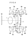
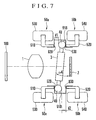
Figs. 4 to 7 are views aiding in explaining the
control of the inclination position of the parallel-plane
plate 3 which performs vertical pixel shifting. The main
feature of the arrangement of the first embodiment resides
in the relative positional relation between the recesses 91U
and 91D and the setting of the width of each of the recesses
91U and 91D.
Figs. 4 to 7 respectively show different
inclination positions of the parallel-plane plate 3 for
sequentially shifting down the incident position of a light
beam which corresponds to one point on a subject, on the
image pickup surface of the image pickup element 2.
Referring to Fig. 4, the dimensions of the recess
91U in which the armature 4U provided at the top end of the
parallel-plane plate 3 is movably fitted and those of the
recess 91D in which the armature 4D provided at the bottom
end of the parallel-plane plate 3 is movably fitted are set
in such a manner that the widths of the recesses 91U and
91D, i.e., the lengths of the recesses 91U and 91D in the
direction of the optical axis, are approximately equal to
each other, and the positions of the recesses 91U and 91D
are approximately the same as each other.
Referring to the upper portion of Fig. 4, the
electromagnet 5Ua is on and electromagnet 5Ub is off, so
that, in the recess 91U, the armature 4U is attracted to the
yoke 51U of the electromagnet 5Ua and positioned by abutment
with the position restricting surface 92U which is located
before the armature 4U in the direction of the optical axis.
Referring to the lower portion of Fig. 4, the electromagnet
5Da is off and the electromagnet 5Db is on, so that the
armature 4D is attracted to the yoke 52D of the
electromagnet 5Db and positioned by abutment with the
position restricting surface 93D which is located behind the
armature 4D in the direction of the optical axis.
In the first embodiment, when the pixel shifting
system is in the state shown in Fig. 4, the parallel-plane
plate 3 is set to perform upward pixel shifting with respect
to the optical axis, but none of the states of inclination
shown in Figs. 4, 5, 6 and 7 is absolute. The present pixel
shifting system is intended to allow an image which
originally cannot be incident on the image pickup surface to
be made incident thereon according to the inclination angle
of the parallel-plane plate 3, and the parallel-plane plate
3 need not be perpendicular to the optical axis in any of
the states shown in Figs. 4, 5, 6 and 7.
Letting d1 be the clearance between the armature
4U and the width of the recess 91U, i.e., the distance
between the armature 4U and the position restricting surface
93U in the recess 91U, and letting d2 be the clearance
between the armature 4D and the width of the recess 91D,
i.e., the distance between the armature 4D and the position
restricting surface 92D in the recess 91D, the relation
between d1 and d2 is set to d2 = d1, i.e., the distance d2
is once as large as, i.e., equal to, the distance d1.
In Fig. 4, ω1 denotes the angle made by the
parallel-plane plate 3 and the image pickup surface of the
image pickup element 2. Incidentally, the distances d1 and
d2 are set with high precision.
In the state shown in Fig. 4, if the electromagnet
5Ua is turned off and the electromagnet 5Ub is turned on and
excited, the armature 4U provided at the top end of the
parallel-plane plate 3 moves away from the position
restricting surface 92U in the recess 91U and is attracted
to the position restricting surface 93U and positioned by
abutment with the position restricting surface 93U. Thus,
the parallel-plane plate 3 goes to the state shown in Fig.
5.
In the state shown in Fig. 5, the inclination
position of the parallel-plane plate 3 is restricted by the
abutment between the armature 4U provided at the top end of
the parallel-plane plate 3 and the position restricting
surface 93U in the recess 91U and by the abutment between
the armature 4D provided at the bottom end of the parallel-plane
plate 3 and the position restricting surface 93D in
the recess 91D. Specifically, the parallel-plane plate 3 is
inclined from the state of Fig. 4 toward the right by one
step as viewed in Fig. 4, and the incident position of the
light beam on the image pickup surface of the image pickup
element 2 is shifted downward on the image pickup surface.
Incidentally, ω2 denotes the angle made by the image pickup
surface and the parallel-plane plate 3 in the state shown in
Fig. 5.
In the state shown in Fig. 5, if the electromagnet
5Ub is turned off and the electromagnet 5Ua is turned on,
the armature 4U moves away from the position restricting
surface 93U in the recess 91U and is attracted to the
position restricting surface 92U and positioned by abutment
with the position restricting surface 92U.
In addition, if the electromagnet 5Db is turned
off and the electromagnet 5Da is turned on, the armature 4D
provided at the bottom end of the parallel-plane plate 3
moves away from the position restricting surface 93D in the
recess 91D and is attracted to the position restricting
surface 92D and positioned by abutment with the position
restricting surface 92D. Thus, the parallel-plane plate 3
goes to the state shown in Fig. 6.
In the state shown in Fig. 6, the inclination
position of the parallel-plane plate 3 is restricted by the
abutment between the armature 4U provided at the top end of
the parallel-plane plate 3 and the position restricting
surface 92U in the recess 91U and by the abutment between
the armature 4D provided at the bottom end of the parallel-plane
plate 3 and the position restricting surface 92D in
the recess 91D. Specifically, the position of the parallel-plane
plate 3 in the direction of the optical axis is moved
from the state of Fig. 5 toward the left with approximately
the same inclination being maintained. (Strictly, the
inclination differs between the states shown in Figs. 5 and
6 because the parallel-plane plate 3 in the state of Fig. 5
and the parallel-plane plate 3 in the state of Fig. 6 are in
abutment with different position restricting surfaces.) The
incident position of the light beam on the image pickup
surface of the image pickup element 2 is approximately the
same on the image pickup surface. Incidentally, ω3 denotes
the angle made by the image pickup surface and the parallel-plane
plate 3 in the state shown in Fig. 6. Thus, ω2 ≅ ω3
and the angle made by the parallel-plane plate 3 and the
optical axis in the state shown in Fig. 5 is the same as the
corresponding angle obtained in the state shown in Fig. 6.
Accordingly, the pixel shifting effects obtained in both
states are the same, and either one of the states may be
selected.
In the following description of the first
embodiment, the state shown in Fig. 5 is selected.
In the state shown in Fig. 5, if the electromagnet
5Db is turned off and the electromagnet 5Da is turned on,
the armature 4D provided at the bottom end of the parallel-plane
plate 3 moves away from the position restricting
surface 93D in the recess 91D and is attracted to the
position restricting surface 92D and positioned by abutment
with the position restricting surface 92D. Thus, the
parallel-plane plate 3 goes to the state shown in Fig. 7.
In the state shown in Fig. 7, the parallel-plane
plate 3 is inclined from the state of Fig. 5 toward the
right as viewed in Fig. 7, and the inclination angle of the
parallel-plane plate 3 reaches a maximum. Incidentally, ω4
denotes the angle made by the image pickup surface and the
parallel-plane plate 3 in the state shown in Fig. 7.
As is apparent from Figs. 4 to 7, by sequentially
varying the inclination of the parallel-plane plate 3 in the
order of ω1, ω2, ω3 and ω4, it is possible to control the
parallel-plane plate 3 to vary its inclination angle in
three steps. Thus, the incident position of the light beam
coming from the subject can be vertically shifted among
three positions on the image pickup surface.
Incidentally, the angles ω1 to ω4 are selected to
satisfy the following relation:
(ω2 - ω1) = (ω4 - ω2) = (ω4 - ω3) = constant,
and this relation indicates that the incident position of
the light beam on the image pickup surface is shifted at an
equal pitch on the image pickup surface according to the
variation in the inclination of the parallel-plane plate 3.
In the first embodiment, the clearance d1 between
the armature 4U and the position restricting surface 92U or
93U in the recess 91U and the clearance d2 between the
armature 4D and the position restricting surface 92D or 93D
in the recess 91D are set so that the amount of shifting for
one step becomes equal to two-thirds of the pixel-to-pixel
distance of the image pickup element. The clearances d1 and
d2, which determine the inclination angle of the parallel-plane
plate 3, are varied according to the pixel-to-pixel
distance of the image pickup element or the amount of
shifting for one step.
As is apparent from the above description, the
parallel-plane plate 3 is supported with some play in such a
manner that the opposite armatures 4U and 4D are movably
fitted in the respective recesses 91U and 91D, and the
inclination angle of the parallel-plane plate 3 is
determined by bringing each of the armatures 4U and 4D into
abutment with either of the position restricting surfaces in
the corresponding one of the recesses 91U and 91D by the
excitation of the associated one of the electromagnets.
Since each of the amatures which comes into abutment with
either of the corresponding position restricting surfaces
has a cylindrical shape, even if the position of abutment of
each of the cylindrical armatures with either of the
corresponding position restricting surfaces deviates in a
longitudinal direction of the parallel-plane plate 3, the
inclination angle of the parallel-plane plate 3 does not
vary, so that the incident position of the light beam on the
image pickup surface of the image pickup element does not
vary.
Furthermore, if the positions of the respective
recesses 91U and 91D are made the same in the direction of
the optical axis, even if the inclination angle of the
parallel-plane plate 3 varies, the central position of the
parallel-plane plate 3 in the direction of the optical axis
does not vary to a great extent, so that accurate pixel
shifting can be effected at all times.
Incidentally, since each of the armatures has a
cylindrical shape, when the armature is attracted by the
electromagnetic force of the corresponding electromagnet,
the portion of the armature which comes into closest
proximity to either of the corresponding position
restricting surfaces forms a point (actually, a line).
Accordingly, the parallel-plane plate 3 is centered by the
position of the armature of the electromagnet, and
substantially does not suffer a positional deviation.
The respective mounting positions of the yokes
51U, 52U, 51D and 52D of the electromagnets 5Ua, 5Ub, 5Da
and 5Db are set so that the respective tips of the yokes
51U, 52U, 51D and 52D do not project from the position
restricting surfaces 92U, 93U, 92D and 93D in the recesses
91U and 91D. Thus, the parallel-plane plate 3 is positioned
by the position restricting surfaces in each of the recesses
at all times, so that the parallel-plane plate 3 can be
positioned with high accuracy without being affected by the
accuracy of the mounting positions of the electromagnets.
In the above-described arrangement, the
inclination of the parallel-plane plate 3 is set so that the
incident position of the light beam on the image pickup
surface is shifted at a pitch of two-thirds of the pixel-to-pixel
distance of the image pickup surface, i.e., at a two-third
pixel pitch for each inclination angle. Accordingly,
it is possible to obtain the number of pixels which is
substantially three times the number of vertical pixels of
an actual image pickup element.
Thus, three images are picked up by the image
pickup element for the respective inclination positions of
the parallel-plane plate 3, and the picked-up three images
are sequentially stored in a memory. During reading from
the memory, the order of reading of each pixel of the three
images is controlled so that the three images can be
combined into one image of high image quality.
The above description has referred to the vertical
pixel shifting on the image pickup surface. However, since
the first embodiment of the present invention is also
provided with a similar pixel shifting mechanism which
performs horizontal pixel shifting, the first embodiment is
capable of performing horizontal pixel shifting so that the
number of pixels of the image pickup element can be made
substantially three times, i.e., nine times in total.
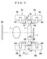
Figs. 8 to 11 are views aiding in explaining the
operation of performing horizontal pixel shifting by
sequentially varying the inclination angle of the horizontal
parallel-plane plate 6.
Since the arrangement and the operation principle
of the horizontal pixel shifting mechanism are the same as
those of the vertical pixel shifting mechanism shown in
Figs. 4 to 7, the detailed description of the horizontal
pixel shifting mechanism is omitted herein.
Incidentally, the inclination angle of the
parallel-plane plate 6 is determined by position restricting
surfaces 92L and 93L of a left recess 91L in which the
armature 7L mounted at the left end of the parallel-plane
plate 6 is movably fitted and position restricting surfaces
92R and 93R of a right recess 91R in which the armature 7R
mounted at the right end of the parallel-plane plate 6 is
movably fitted. Letting d3 be the clearance between the
armature 7L and the width of the recess 91L, and letting d4
be the clearance between the armature 7R and the width of
the recess 91R, the relation between d3 and d4 is set to d3
= d4 in the first embodiment.
In the above-described arrangement, if the angle
made by the image pickup surface and the parallel-plane
plate 6 is stepwise varied (increased) in the order of ω5,
ω6, ω7 and ω8 while the inclination angle of the parallel-plane
plate 6 is being increased in the order of Figs. 8, 9,
10 and 11, horizontal pixel shifting at an equal pitch can
also be performed on the image pickup surface.
Incidentally, the angles ω5 to ω8 are selected to
satisfy the following relation:
(ω6 - ω5) = (ω8 - ω6) = (ω8 - ω7) = constant.
In the first embodiment, the clearance d3 between
the armature 7L and the position restricting surface 92L or
93L in the recess 91L and the clearance D4 between the
armature 7R and the position restricting surface 92R or 93R
in the recess 91R are set so that the amount of shifting for
one step becomes equal to two-thirds of the horizontal
pixel-to-pixel distance of the image pickup element. The
clearances d3 and d4, which determine the inclination angle
of the parallel-plane plate 6, are varied according to the
pixel-to-pixel distance of the image pickup element or the
amount of shifting for one step.
Incidentally, although the vertical pixel shifting
shown in Figs. 4 to 7 and the horizontal pixel shifting
shown in Figs. 8 to 11 are performed so as to sequentially
increase the respective inclination angles of the parallel- plane
plates 3 and 6, images are picked up for the
respective inclination positions and stored in the memory so
that the images can be combined into one image by processing
to be performed at a later time. For this reason, the
respective inclination angles of the parallel- plane plates 3
and 6 may be varied in arbitrary order. In other words, the
vertical pixel shifting and the horizontal pixel shifting
need not be limited to the order shown in Figs. 4 to 7 and
the order shown in Figs. 8 to 11, and may be performed in
arbitrary order as long as three images in the vertical
direction and three images in the horizontal image, a total
of nine images, can be picked up by controlling each of the
electromagnets.
Furthermore, since the vertical pixel shifting
mechanism and the horizontal pixel shifting mechanism are
independent of each other, the direction and the order of
pixel shifting by each of the vertical and horizontal pixel
shifting mechanisms may be arbitrary. As a matter of
course, each of the parallel plates must be kept stationary
during an image pickup (charge storage) operation for each
pixel shifting position.
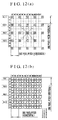
Figs. 12(a) and 12(b) are diagrammatic views
showing the spatial positions of the pixels obtained when
pixel shifting is performed on the basis of a combination of
the three states, shown in Figs. 4 to 7, of the parallel-plane
plate 3 for vertical pixel shifting and the three
states, shown in Figs. 8 to 11, of the parallel-plane plate
6 for horizontal pixel shifting.
A method of shifting a light beam to obtain data
will be described below with reference to Figs. 12(a) and
12(b).
In Fig. 12(a), the locations shaded by hatching
(four kinds of hatching such as cross-hatching) show part of
the positions of pixels (photosensitive portions) on an
image pickup element such as an interline transfer type CCD.
As shown in Fig. 12(a), the portion (non-photosensitive
portion) between each of the pixels and the neighboring
pixel is divided into two parts to divide one pixel pitch by
three so that the image pickup surface of the image pickup
element is divided in a checkered pattern.
As shown in Fig. 12(a), for example, the
photosensitive portion denoted by symbol A can capture light
beams incident on nine locations which are respectively
defined by nine coordinates (H5, L5), (H5, L7), (H5, L9),
(H7, L5), (H7, L7), (H7, L9), (H9, L5), (H9, L7) and (H9,
L9), on the basis of the combination of the three states,
shown in Figs. 4 to 7, of the parallel-plane plate 3 for
vertical pixel shifting and the three states, shown in Figs.
8 to 11, of the parallel-plane plate 6 for horizontal pixel
shifting. The light beams incident on the respective nine
locations are conducted to the photosensitive portion A on a
beam-by-beam basis (by pixel shifting), and the stored data
(the charge stored in the photosensitive portion A) is read
during reading of field data from the photosensitive portion
A. A similar operation is performed during reading of field
data from each of the other photosensitive portions.
In consequence, as shown in Fig. 12(b), it is
possible to obtain, by pixel shifting, data indicative of
light beams which are incident on the non-photosensitive
portion which surrounds each photosensitive portion.
In other words, it is possible to obtain image
information carried by a light beam which would originally
be incident on the non-photosensitive portion between each
pixel on the image pickup surface or on a pixel other than a
predetermined pixel. In consequence, it is possible to
achieve an effect equivalent to an increase in the number of
pixels per image pickup element.
As described above, in the arrangement and the
operation of the pixel shifting system according to the
first embodiment of the present invention, two parallel-plane
plates which respectively perform vertical pixel
shifting and horizontal pixel shifting are disposed
independently of each other, and during an image pickup
operation, the inclination angles of the parallel-plane
plates are shifted, one in the vertical direction and the
other in the horizontal direction, at a pitch of two-thirds
of the pixel-to-pixel distance of the image pickup surface.
In this manner, it is possible to obtain an image quality
equivalent to the number of pixels which is substantially
three times the actual number of pixels with respect to each
of the vertical and horizontal directions, i.e., a total of
nine times the actual number of pixels.
(Second Embodiment)
A second embodiment of the present invention will
be described below. Although the first embodiment shown in
Figs. 4 to 11 is arranged to perform pixel shifting of three
steps in each of the vertical and horizontal directions, the
second embodiment is capable of performing pixel shifting of
four steps in each of the vertical and horizontal
directions.
In the second embodiment, parallel-plane plates,
recesses for positioning the parallel-plane plates, and
electromagnets which constitute driving means are arranged
in a manner similar to that described previously in
connection with the first embodiment, and the feature of the
second embodiment can be realized by modifying the
positional relation between the recesses.
Figs. 13 to 16 are views aiding in explaining the
control of the inclination position of the parallel-plane
plate 3 which performs vertical pixel shifting of four
steps. The main feature of the arrangement of the second
embodiment resides in the relative positional relation
between recesses 91U' and 91D' and the setting of the width
of each of the recesses 91U' and 91D'.
Figs. 13 to 16 respectively show different
inclination positions of the parallel-plane plate 3 for
sequentially shifting down the incident position of a light
beam which corresponds to one point on a subject, on the
image pickup surface of the image pickup element 2. In the
following description, identical reference numerals are used
to denote constituent parts identical to those of the first
embodiment shown in Figs. 4 to 11.
Referring to Fig. 13, the dimensions of the recess
91U' in which the armature 4U provided at the top end of the
parallel-plane plate 3 is movably fitted and those of the
recess 91D' in which the armature 4D provided at the bottom
end of the parallel-plane plate 3 is movably fitted are set
in such a manner that the widths of the recesses 91U' and
91D', i.e., the lengths of the recesses 91U' and 91D' in the
direction of the optical axis, are different from each
other, and the positions of the recesses 91U and 91D are
different from each other.
Referring to the upper portion of Fig. 13, the
electromagnet 5Ua is on and electromagnet 5Ub is off, so
that, in the recess 91U', the armature 4U is attracted to
the yoke 51U of the electromagnet 5Ua and positioned by
abutment with a position restricting surface 92U' which is
located before the armature 4U in the direction of the
optical axis. Referring to the lower portion of Fig. 13,
the electromagnet 5Da is off and the electromagnet 5Db is
on, so that the armature 4D is attracted to the yoke 52D of
the electromagnet 5Db and positioned by abutment with a
position restricting surface 93D' which is located behind
the armature 4D in the direction of the optical axis.
In the second embodiment, when the pixel shifting
system is in the state shown in Fig. 13, the parallel-plane
plate 3 is set to have a perpendicular positional relation
to the optical axis, but none of the states of inclination
shown in Figs. 13, 14, 15 and 16 is absolute. The present
pixel shifting system is intended to allow an image which
originally cannot be incident on the image pickup surface to
be made incident thereon according to the inclination angle
of the parallel-plane plate 3, and the parallel-plane plate
3 need not be perpendicular to the optical axis in any of
the state shown in Fig. 13.
Letting d1' be the clearance between the armature
4U and the width of the recess 91U', i.e., the distance
between the armature 4U and the position restricting surface
93U' in the recess 91U', and letting d2' be the clearance
between the armature 4D and the width of the recess 91D',
i.e., the distance between the armature 4D and the position
restricting surface 92D' in the recess 91D', the relation
between d1' and d2' is set to d2' = d1', i.e., the distance
d2' is twice as large as the distance d1'.
In Fig. 13, ω1' denotes the angle made by the
parallel-plane plate 3 and the image pickup surface of the
image pickup element 2. Incidentally, the distances d1' and
d2' are set with high precision.
In the state shown in Fig. 13, if the
electromagnet 5Ua is turned off and the electromagnet 5Ub is
turned on and excited, the armature 4U provided at the top
end of the parallel-plane plate 3 moves away from the
position restricting surface 92U' in the recess 91U' and is
attracted to the position restricting surface 93U' and
positioned by abutment with the position restricting surface
93U'. Thus, the parallel-plane plate 3 goes to the state
shown in Fig. 14.
In the state shown in Fig. 14, the inclination
position of the parallel-plane plate 3 is restricted by the
abutment between the armature 4U provided at the top end of
the parallel-plane plate 3 and the position restricting
surface 93U' in the recess 91U' and by the abutment between
the armature 4D provided at the bottom end of the parallel-plane
plate 3 and the position restricting surface 93D' in
the recess 91D'. Specifically, the parallel-plane plate 3
is inclined from the state of Fig. 13 toward the right by
one step as viewed in Fig. 13, and the incident position of
the light beam on the image pickup surface of the image
pickup element 2 is shifted downward on the image pickup
surface. Incidentally, ω2' denotes the angle made by the
image pickup surface and the parallel-plane plate 3 in the
state shown in Fig. 14.
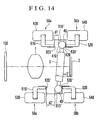
In the state shown in Fig. 14, if the
electromagnet 5Ub is turned off and the electromagnet 5Ua is
turned on, the armature 4U moves away from the position
restricting surface 93U' in the recess 91U' and is attracted
to the position restricting surface 92U' and positioned by
abutment with the position restricting surface 92U'.
In addition, if the electromagnet 5Db is turned
off and the electromagnet 5Da is turned on, the armature 4D
provided at the bottom end of the parallel-plane plate 3
moves away from the position restricting surface 93D' in the
recess 91D' and is attracted to the position restricting
surface 92D' and positioned by abutment with the position
restricting surface 92D'. Thus, the parallel-plane plate 3
goes to the state shown in Fig. 15.
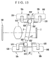
In the state shown in Fig. 15, the inclination
position of the parallel-plane plate 3 is restricted by the
abutment between the armature 4U provided at the top end of
the parallel-plane plate 3 and the position restricting
surface 92U' in the recess 91U' and by the abutment between
the armature 4D provided at the bottom end of the parallel-plane
plate 3 and the position restricting surface 92D' in
the recess 91D'. Specifically, the parallel-plane plate 3
is further inclined from the state of Fig. 14 toward the
right by one step as viewed in Fig. 14, and the incident
position of the light beam on the image pickup surface of
the image pickup element 2 is shifted further downward on
the image pickup surface. Incidentally, ω3' denotes the
angle made by the image pickup surface and the parallel-plane
plate 3 in the state shown in Fig. 15.
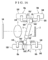
In the state shown in Fig. 15, if the
electromagnet 5Ua is turned off and the electromagnet 5Ub is
turned on, the armature 4U provided at the top end of the
parallel-plane plate 3 moves away from the position
restricting surface 92U' in the recess 91U' and is attracted
to the position restricting surface 93U' and positioned by
abutment with the position restricting surface 93U'. On the
other hand, the armature 4D provided at the bottom end of
the parallel-plane plate 3 is positioned by the position
restricting surface 92D' in the recess 91D'. Thus, the
parallel-plane plate 3 goes to the state shown in Fig. 16.
In the state shown in Fig. 16, the parallel-plane
plate 3 is further inclined from the state of Fig. 15 toward
the right as viewed in Fig. 16, and the inclination angle of
the parallel-plane plate 3 reaches a maximum. Incidentally,
ω4' denotes the angle made by the image pickup surface and
the parallel-plane plate 3 in the state shown in Fig. 16.
As is apparent from Figs. 13 to 16, by
sequentially varying the inclination of the parallel-plane
plate 3 in the order of ω1', ω2', ω3' and ω4', it is
possible to control the parallel-plane plate 3 to vary its
inclination angle in four steps. Thus, the incident
position of the light beam coming from the subject can be
vertically shifted among four positions on the image pickup
surface.
Incidentally, the angles ω1' to ω4' are selected
to satisfy the following relation:
(ω2' - ω1') = (ω3' - ω2') = (ω4' - ω3')
= constant,
and this relation indicates that the incident position of
the light beam on the image pickup surface is shifted at an
equal pitch on the image pickup surface according to the
variation in the inclination of the parallel-plane plate 3.
In the second embodiment, the clearance d1'
between the armature 4U and the position restricting surface
92U' in the recess 91U' and the clearance d2' between the
armature 4D and the position restricting surface 93D' in the
recess 91D' are set so that the amount of shifting for one
step becomes equal to half of the pixel-to-pixel distance of
the image pickup element. The clearances d1' and d2', which
determine the inclination angle of the parallel-plane plate
3, are varied according to the pixel-to-pixel distance of
the image pickup element or the amount of shifting for one
step.
Since each of the armatures which comes into
abutment with either of the corresponding position
restricting surfaces has a cylindrical shape, even if the
position of abutment of each of the cylindrical armatures
with either of the corresponding position restricting
surfaces deviates in a longitudinal direction of the
parallel-plane plate 3, the inclination angle of the
parallel-plane plate 3 does not vary, so that the incident
position of the light beam on the image pickup surface of
the image pickup element does not vary.
In the above-described arrangement, the
inclination of the parallel-plane plate 3 is set so that the
incident position of the light beam on the image pickup
surface is shifted at a pitch of half of the pixel-to-pixel
distance of the image pickup surface, i.e., at a half pixel
pitch for each inclination angle. Accordingly, it is
possible to obtain the number of pixels which is
substantially four times the number of vertical pixels of an
actual image pickup element.
Thus, four images are picked up by the image
pickup element for the respective inclination positions of
the parallel-plane plate 3, and the picked-up four images
are sequentially stored in a memory. During reading from
the memory, the order of reading of each pixel of the four
images is controlled so that the four images can be combined
into one image of high image quality.
The above description has referred to the vertical
pixel shifting on the image pickup surface. However, since
the second embodiment of the present invention is also
provided with a similar pixel shifting mechanism which
performs horizontal pixel shifting, the second embodiment is
capable of performing horizontal pixel shifting so that the
number of pixels of the image pickup element can be made
substantially four times, i.e., sixteen times in total.
Figs. 17 to 20 are views aiding in explaining the
operation of performing horizontal pixel shifting by
sequentially varying the inclination angle of the horizontal
parallel-plane plate 6.
Since the arrangement and the operation principle
of the horizontal pixel shifting mechanism are the same as
those of the vertical pixel shifting mechanism shown in
Figs. 13 to 16, the detailed description of the horizontal
pixel shifting mechanism is omitted herein.
Incidentally, the inclination angle of the
parallel-plane plate 6 is determined by position restricting
surfaces 92L' and 93L' of a left recess 91L' in which the
armature 7L mounted at the left end of the parallel-plane
plate 6 is movably fitted and position restricting surfaces
92R' and 93R' of a right recess 91R' in which the armature
7R mounted at the right end of the parallel-plane plate 6 is
movably fitted. Letting d3' be the clearance between the
armature 7L and the width of the recess 91L', and letting
d4' be the clearance between the armature 7R and the width
of the recess 91R', the relation between d3' and d4' is set
to d4' = 2d3' in the second embodiment.
In the above-described arrangement, if the angle
made by the image pickup surface and the parallel-plane
plate 6 is stepwise varied (increased) in the order of ω5',
ω6', ω7' and ω8' while the inclination angle of the
parallel-plane plate 6 is being increased in the order of
Figs. 17, 18, 19 and 20, horizontal pixel shifting at an
equal pitch can also be performed on the image pickup
surface.
Incidentally, the angles ω5' to ω8' are selected
to satisfy the following relation:
(ω6' - ω5') = (ω7' - ω6') = (ω8' - ω7')
= constant.
In the second embodiment, the clearance d3'
between the armature 7L and the position restricting surface
92L' or 93L' in the recess 91L' and the clearance D4 between
the armature 7R and the position restricting surface 92R' or
93R' in the recess 91R' are set so that the amount of
shifting for one step becomes equal to half of the
horizontal pixel-to-pixel distance of the image pickup
element. The clearances d3' and d4', which determine the
inclination angle of the parallel-plane plate 6, are varied
according to the pixel-to-pixel distance of the image pickup
element or the amount of shifting for one step.
Incidentally, although the vertical pixel shifting
shown in Figs. 13 to 16 and the horizontal pixel shifting
shown in Figs. 17 to 20 are performed so as to sequentially
increase the respective inclination angles of the parallel- plane
plates 3 and 6, images are picked up for the
respective inclination positions and stored in the memory so
that the images can be combined into one image by processing
to be performed at a later time. For this reason, the
respective inclination angles of the parallel- plane plates 3
and 6 may be varied in arbitrary order. In other words, the
vertical pixel shifting and the horizontal pixel shifting
need not be limited to the order shown in Figs. 13 to 16 and
the order shown in Figs. 17 to 20, and may be performed in
arbitrary order as long as four images in the vertical
direction and four images in the horizontal image, a total
of sixteen images, can be picked up by controlling each of
the electromagnets.
Furthermore, since the vertical pixel shifting
mechanism and the horizontal pixel shifting mechanism are
independent of each other, the direction and the order of
pixel shifting by each of the vertical and horizontal pixel
shifting mechanisms may be arbitrary. As a matter of
course, while one image is being picked up, each of the
parallel plates must be kept stationary.
Fig. 21 shows variations on a pixel-by-pixel basis
in the incident position of a light beam on the image pickup
surface, which variations correspond to the respective four
states of the parallel-plane plate 3 shown in Figs. 13 to
20.
In Fig. 21, the respective states of Figs. 13 to
16 are conceptually shown in parts (1), (2), (3) and (4).
By sequentially varying the inclination of the parallel-plane
plate 3, the incident position of a light beam which
would originally be made incident on only one point on the
image pickup surface can be shifted among four locations.
Accordingly, four light beams incident on four different
locations which are spaced vertically apart from one another
and some of which lie between vertically adjacent pixels,
can be made incident on one pixel on the image pickup
surface of the image pickup element.
In other words, it is possible to obtain image
information carried by a light beam which would originally
be incident on a non-photosensitive portion between each
pixel on the image pickup surface or on a pixel other than a
predetermined pixel. In consequence, it is possible to
achieve an effect equivalent to an increase in the number of
pixels per image pickup element.
In Fig. 21, reference numeral 2a denotes an image
pickup surface of the image pickup element 2. Four kinds of
color filters which respectively constitute pixels Cy
(cyan), Ye (yellow), G (green) and Mg (magenta) are disposed
on the image pickup surface 2a as shown in Fig. 21, and
these four pixels constitute one pixel in the case of color
image pickup.
As viewed in Fig. 21 in the vertical direction, if
the inclination angle of the parallel-plane plate 3 is
varied with respect to the optical axis, a light beam to be
made incident on one position is sequentially shifted among
four vertical locations which contain positions between
adjacent pixels in which pixels are originally absent. In
other words, it is possible to obtain, from each pixel,
image information which originally cannot be obtained at
that position because the incident position of a light beam
indicative of the image information lies between adjacent
pixels.
Furthermore, in accordance with the second
embodiment of the present invention, since vertical four-step
pixel shifting and horizontal four-step pixel shifting
are performed without making a light beam incident on the
same color pixel, it is possible to obtain the number of
pixels which is simply substantially sixteen times (4 × 4)
the number of pixels of the image pickup element 2, as shown
in Part A of fig. 21. In the case of an image pickup
element having 1,300,000 pixels, if the pixel shifting
system according to the present invention is applied to
pixel shifting in either vertical or horizontal direction,
it is possible to obtain an image of high quality which is
equivalent to that of an image picked up by an image pickup
element of 1,300,000 × 4 = 5,200,000 pixels.
Accordingly, if the present pixel shifting is
performed in both vertical and horizontal directions, it is
possible to obtain an image of high quality which is
equivalent to 5,200,000 × 4 = 20,800,000 pixels.
(Third Embodiment)
A third embodiment of the pixel shifting system
according to the present invention will be described below.
As compared with the first embodiment, the feature
of the third embodiment resides in a simplified driving
system which includes electromagnets for driving parallel-plane
plates, and reduced power consumption.
Figs. 22(a) and 22(b) show the essential portion
of the third embodiment. Fig. 22(a) is a front elevational
view taken in the direction of the optical axis, and Fig.
22(b) is a top plan view.
As shown in each of Figs. 22(a) and 22(b), the
third embodiment differs from the first embodiment in that
part of the electromagnets used in the first embodiment are
replaced with springs. In Figs. 22(a) and 22(b), identical
reference numerals are used to denote constituent elements
identical to those used in the first embodiment, and the
description of such constituent elements is omitted for the
sake of simplicity.
Specifically, the electromagnets 5Ua, 5Da, 8La and
8Ra (shown in Fig. 1(a)) are replaced with springs for
urging the parallel-plane plates in the forward direction
along the optical axis.
These springs are substituted for the attractions
of the respective electromagnets 5Ua, 5Da, 8La and 8Ra, and
the movement of each of the parallel-plane plates against
the associated springs is achieved by the magnetic
attraction of the corresponding ones of the electromagnets
5Ub, 5Db, 8Lb and 8Rb. With this arrangement, it is
possible to reduce the required number of electromagnets
(eight, in the first embodiment) to half (four, in the third
embodiment).
Referring to Fig. 22(b), springs 10L and 10R for
pulling the respective armatures 7L and 7R of the horizontal
parallel-plane plate 6 in the forward direction along the
optical axis are provided instead of the electromagnets 8La
and 8Ra.
Although not shown, other springs are provided
instead of the electromagnets 5Ua, 5Da, 8La and 8Ra shown in
Fig. 1(a), and the arrangement of the springs will readily
be understood from Figs. 22(a) and 22(b).
Since the vertical pixel shifting operation of the
parallel-plane plate 3 and the horizontal pixel shifting
operation of the parallel-plane plate 6 are as described
previously with reference to Figs. 4 to 11, 13 to 16 and 17
to 20 in connection with the first and second embodiments,
the description of the operation of the third embodiment is
omitted herein.
The arrangement and the operation of the pixel
shifting system according to the present invention are as
described above, and the following description will refer to
an arrangement in which such a pixel shifting system is
actually incorporated in a lens barrel or a camera body.
Fig. 23(a) is an exploded perspective view of a
pixel shifting unit in which the pixel shifting mechanism
according to the first (or second) embodiment of the present
invention is incorporated.
In Fig. 23(a), reference numerals 9 and 9' denote
frames each of which supports the corresponding
electromagnets and parallel-plane plates. The frames 9 and
9' are separated from each other in the direction of the
optical axis, and each of them has an opening through which
to pass a light beam at a location centered about the
optical axis.
The electromagnets 5Ub, 5Db, 8Lb and 8Rb are
disposed at predetermined positions of the joining surface
of the rear frame 9' which surrounds the opening 9a of the
rear frame 9 and is opposed to the front frame portion 9'.
The position restricting surface 93U and 93D; 93L and 93R
are respectively formed in the recesses 91U and 91D; 91L and
91R into which to insert the vertical and horizontal
parallel- plane plates 3 and 6, respectively.
The respective yokes 52U and 52D of the
electromagnets 5Ub and 5Db are exposed at positions opposed
to the armatures 4U and 4D of the parallel-plane plate 3,
while the respective yokes 82L and 82R of the respective
electromagnets 8Lb and 8Rb are exposed at positions opposed
to the armatures 7L and 7R of the parallel-plane plate 6.
The front frame 9' which is opposed to the rear
frame 9 has the electromagnets 5Ua, 5Ub, 5Da and 5Db at
positions opposed to the respective electromagnets 5Ub, 5Db,
8Lb and 8Rb. The position restricting surface 92U, 92D, 92L
and 92R are respectively formed in the recesses 91U, 91D,
91L and 91R.
Accordingly, by connecting the front frame 9' and
the rear frame 9, the vertical and horizontal parallel- plane
plates 3 and 6 and the electromagnets for controlling the
positions of the parallel- plane plates 3 and 6 can be
supported as shown in Figs. 1 to 11 and 13 to 20.
Fig. 23(b) is an exploded perspective view showing
in detail the arrangement of the pixel shifting unit shown
in Fig. 23(a) and its peripheral members. In Fig. 23(b),
identical reference numerals are used to denote constituent
elements identical to those shown in Fig. 23(a), and the
description thereof is omitted for the sake of simplicity.
In actual incorporation into a product, each pair of the
opposed electromagnets (5Ua and 5Ub, 5Da and 5Db, 8La and
8Lb, 8Ra and 8Rb) is integrated into one unit and the spaces
between the opposed yokes 51U and 52U, 51D and 52D, 81L and
82L, and 81R and 81L are restricted by spacers 85L, 85R, 85U
and 85D, respectively. In addition, since the peripheral
portion of the pixel shifting unit is restricted, the pixel
shifting unit can be readily incorporated.
The parallel- plane plates 3 and 6 are respectively
supported by support frames 31 and 61, and a pair of
cylindrical armatures each of which comes into abutment with
either of the corresponding yokes are mounted at the
opposite ends of each of the parallel- plane plates 3 and 6.
These electromagnet units and the parallel-plane
plates are supported in the space formed between the front
frame 9' and the rear frame 9.
In Fig. 23(b), reference numeral 202 denotes a
low-pass filter, and reference numeral 209 denotes a member
for connecting the pixel shifting unit composed of the
frames 9' and 9 to a lens unit which will be described
later.
A low-pass filter 203 which differs in low-pass
filtering direction from the low-pass filter 202 is
supported for rotation about the optical axis in the rear
frame 9 by a low-pass filter supporting frame 206, and a
gear portion 204 disposed around the low-pass filter 203 is
rotationally controlled by a motor 205.
The low-pass effect of the low- pass filters 202
and 203 can be turned on or off by the relative rotation
between the low- pass filters 202 and 203. Specifically,
during a moving-image pickup mode or a normal-resolution
image pickup mode, the low- pass filters 202 and 203 are
controlled to serve a low-pass filter function, whereas
during a high-resolution image pickup mode which uses pixel
shifting, the low- pass filters 202 and 203 are controlled to
cancel the low-pass filter function.
In other words, the low-pass effect of the low- pass
filters 202 and 203 can be controlled by rotationally
driving the motor 205 according to the kind of image pickup
mode.
The CCD image pickup element 2 is positionally
adjustably mounted on a base plate 207 via a mounting
support plate 208 behind the low-pass filter supporting
frame 206.
If the structure shown in Fig. 23(b) is integrated
with a lens unit, it is possible to realize a lens unit
provided with a pixel shifting system. This feature makes
it possible to realize an interchangeable lens provided with
a pixel shifting mechanism.
Fig. 24 is a cross-sectional side view showing an
arrangement in which the aforesaid pixel shifting unit is
incorporated in a lens unit or a camera body.
As shown in Fig. 24, a photographing lens optical
system 1 is disposed in a lens barrel 200, and the pixel
shifting unit shown in Fig. 23(a) is disposed on the mount
portion of the lens barrel 200.
The pixel shifting unit is composed of the front
frame 9' and the rear frame 9. As shown in Fig. 24, the LPF
(optical low-pass filter) 202 for limiting the spatial
frequency of an incident light beam, the horizontal
parallel-plane plate 6, the vertical parallel-plane plate 3
and the LPF (optical low-pass filter) 203 are disposed in
that order in the pixel shifting unit, and the image pickup
element 2 is disposed behind the pixel shifting unit. In
Fig. 24, reference numeral 2a denotes an effective image
pickup surface (image pickup area) of the image pickup
element 2, and reference numeral 2b denotes a sealing glass
for the image pickup surface of the image pickup element 2.
An infrared cut-filter may be disposed, as by
coating a surface of the parallel- plane plate 3 or 6.
Further, the parallel- plane plate 3 or 6 is made of infrared
absorption glass.
The LPFs 202 and 203 cooperate in band-limiting
the spatial frequency of an incident light beam, thereby
eliminating moiré or the like due to a fold-back effect.
The LPF 203 is rotatably disposed so that the effect of the
LPFs 202 and 203 can be cancelled by rotating the wavelength
of the incident light beam according to the rotation of the
LPF 203.
Accordingly, if it is necessary to remove the
band-limiting effect of the LPFs 202 and 203 in order to
pick up an image of particularly high quality, the LPFs 202
and 203 need only to be relatively rotated without being
removed from the camera body. An arrangement for relatively
rotating these two optical low-pass filters and cancelling
the low-pass function thereof, and the contents of the
operation of such arrangement are described in detail in
Japanese Laid-Open Patent Application No. Hei 7-245762, and
the description of the arrangement is omitted herein for the
sake of simplicity.
A circuit (image processing circuit) for driving
the aforesaid pixel shifting mechanism will be described
below with reference to Fig. 25.
Referring to Fig. 25, a pixel shifting unit is
disposed in the space between the image pickup lens unit 1
and the image pickup element 2.
A picked-up image signal outputted from the image
pickup element 2 is stored in a memory 301. The image data
read from the memory 301 is supplied to a camera process
circuit 302, and the camera process circuit 302 produces a
luminance signal and a chrominance signal. The luminance
signal and the chrominance signal are supplied to a
recording/reproducing system 306 and recorded on a recording
medium which not shown.
The luminance signal and the chrominance signal
are also supplied to a display control circuit 304. The
display control circuit 304 converts both signals into a
signal format suited to display on a monitor, and the
obtained signal is visually displayed on a monitor display
305.
In addition, the output signal of the camera
process circuit 302 may be directly outputted to an external
apparatus such as a personal computer through a digital
image output terminal DO in the form of a digital image
signal.
The image processing circuit having the above-described
arrangement is controlled by a system control
circuit 307 composed of a microcomputer.
In other words, a pixel shifting unit 300 is
controlled to sequentially control the vertical and
horizontal parallel-plane plates, thereby performing pixel
shifting.
In the third embodiment of the present invention,
the system control circuit 307 controls the parallel-plane
plate 3 to perform vertical pixel shifting of four steps
and, in each of the four steps, controls the parallel-plane
plate 6 to perform horizontal pixel shifting of four steps.
Accordingly, it is possible to obtain four images in the
vertical direction and four images in the horizontal
direction, a total of sixteen images.
Each of these images is sequentially stored in the
memory 301 which is being controlled by a memory controller
303. After all the images have been stored in the memory
301, the images are read from the memory 301 to combine the
images into one image, while reading from the memory 301 is
being sequentially controlled on a pixel-by-pixel basis.
The obtained image signal is supplied to the camera process
circuit 302, in which it is subjected to luminance signal
processing and chrominance signal processing so that an
image signal of high image quality can be obtained.
Incidentally, the signal read from the memory 301
may be outputted to an external apparatus such as a personal
computer so that various kinds of image processing can be
performed on the side of the external apparatus.
With the above-described processing, it is
possible to pick up an image of high image quality which is
equivalent to that of an image picked up by an image pickup
element, the number of pixels of which is greater than the
actual number of pixels of the image pickup element 2.
As described above, in the pixel shifting system
according to each of the embodiments of the present
invention, not motors but electromagnetic driving means such
as electromagnets are used as a driving source in the pixel
shifting system, while not mechanisms such as complicated
cams but abutment spaces are used as position controlling
means in the pixel shifting system, and the abutment spaces
for position control have different sizes so that the
respective inclination positions of pixel shifting optical
elements such as parallel-plane plates are individually
controlled. Accordingly, the number of members which need
to have high dimensional accuracy can be minimized, and
particular support shafts for controlling the inclination
positions of the optical elements can be eliminated, so that
it is possible to realize a pixel shifting system which is
capable of obtaining a plurality of stable optical positions
by means of a simple mechanism which can operate at high
speed by a simple control method.
As is apparent from the foregoing description, in
each of the embodiments of the present invention, a
plurality of restricting portions for restricting the
position of an optical element movable in the direction of
the optical axis are formed at the opposite ends of the
optical element for shifting the incident position of a
light beam on a image pickup surface, and the inclination
position of the optical element is controlled by bringing
the optical element into selective abutment with the
restricting portions. Accordingly, a pixel shifting
operation basically can be realized by a simple mechanism
which only brings the optical element into selective
abutment with the restricting portions. In addition, since
the optical element is positioned by being selectively
brought into direct abutment with the restricting surfaces,
an extremely high-speed pixel shifting image pickup
operation can be realized.
In addition, in spite of a simple arrangement, it
is possible to attain extremely high positioning accuracy by
selectively bringing the optical element directly into
abutment with the restricting surfaces. Since it is
unnecessary to use complicated mechanisms which would have
been incorporated in a conventional arrangement, such as a
mechanism for supporting the optical element and a mechanism
such as a cam for controlling the inclination position of
the optical element, it is possible to achieve reductions in
cost and mounting space.
The position restricting surfaces are formed
before and behind each end portion of the optical element in
the direction of the optical axis so that the combination of
the position restricting surfaces which each end portion of
the optical element selectively comes into abutment with can
be modified to control the optical element to cause it to
move among a plurality of inclination angles. In addition,
the inclination angle of the optical element can be
controlled among various angles by appropriately varying the
amount of movement of each end portion of the optical
element and the ratio of the amount of movement at one end
to the amount of movement at the other end. Accordingly, it
is possible to realize high-speed and high-precision pixel
shifting by means of an extremely simple arrangement.
Furthermore, since each engagement part of the
optical element is brought in point or line contact with
either of the corresponding restricting surfaces during
selective abutment therewith, even if a variation occurs in
the position of engagement of the engagement part of the
optical element (parallel-plane plate) with either of the
corresponding restricting surfaces and a positional
deviation of the engagement part occurs in a plane parallel
to the image pickup surface, the angle of inclination of the
optical element can be kept constant and such positional
deviation can be prevented from affecting the amount of
pixel shifting.
Furthermore, since a cylindrical member for line
contact (or a plurality of point contact members) or the
like is employed, it is possible to realize high-precision
positioning without causing a lengthwise inclination of the
cylindrical member with respect to the restricting surfaces.
Furthermore, since the driving means are composed
of a plurality of electromagnets which are provided for the
respective restricting surfaces, it is possible to vary the
inclination position of the optical member at high speed by
means of a simple arrangement which only performs on-off
control of the electromagnets.
Furthermore, since the driving means may be
composed of elastic members and electromagnets, it is
possible to further simplify the arrangement of the pixel
shifting system.
Furthermore, by disposing a plurality of similar
optical elements in an optical path, it is possible to
increase the number of steps for pixel shifting and to
finely control the amount of pixel shifting per step, and it
is also possible to vary the direction of pixel shifting.
Specifically, the optical elements include a
vertical optical element for vertically shifting the
incident position of a light beam on the image pickup
surface and a horizontal optical element for horizontally
shifting the incident position of a light beam on the image
pickup surface, so that it is possible to realize pixel
shifting in both vertical and horizontal directions, i.e., a
further improvement in image quality.
Furthermore, since such optical units are
incorporated in a lens unit, a pixel shifting unit having
the above-described high-speed, high-precision and simple
arrangement can be supplied to various image pickup
apparatus in the form of an integrated lens unit, and the
adjustment required on a user side can be simplified. It
is, therefore, possible to provide a highly versatile
system.