EP0853920A2 - A method for modifying at least one calculation algorithm in a biopsy system and a biopsy system - Google Patents
A method for modifying at least one calculation algorithm in a biopsy system and a biopsy system Download PDFInfo
- Publication number
- EP0853920A2 EP0853920A2 EP97120564A EP97120564A EP0853920A2 EP 0853920 A2 EP0853920 A2 EP 0853920A2 EP 97120564 A EP97120564 A EP 97120564A EP 97120564 A EP97120564 A EP 97120564A EP 0853920 A2 EP0853920 A2 EP 0853920A2
- Authority
- EP
- European Patent Office
- Prior art keywords
- phantom
- biopsy
- biopsy system
- calculation
- calculation algorithm
- Prior art date
- Legal status (The legal status is an assumption and is not a legal conclusion. Google has not performed a legal analysis and makes no representation as to the accuracy of the status listed.)
- Ceased
Links
Images


Classifications
-
- A—HUMAN NECESSITIES
- A61—MEDICAL OR VETERINARY SCIENCE; HYGIENE
- A61B—DIAGNOSIS; SURGERY; IDENTIFICATION
- A61B90/00—Instruments, implements or accessories specially adapted for surgery or diagnosis and not covered by any of the groups A61B1/00 - A61B50/00, e.g. for luxation treatment or for protecting wound edges
- A61B90/36—Image-producing devices or illumination devices not otherwise provided for
-
- A—HUMAN NECESSITIES
- A61—MEDICAL OR VETERINARY SCIENCE; HYGIENE
- A61B—DIAGNOSIS; SURGERY; IDENTIFICATION
- A61B10/00—Other methods or instruments for diagnosis, e.g. instruments for taking a cell sample, for biopsy, for vaccination diagnosis; Sex determination; Ovulation-period determination; Throat striking implements
- A61B10/02—Instruments for taking cell samples or for biopsy
- A61B10/0233—Pointed or sharp biopsy instruments
-
- A—HUMAN NECESSITIES
- A61—MEDICAL OR VETERINARY SCIENCE; HYGIENE
- A61B—DIAGNOSIS; SURGERY; IDENTIFICATION
- A61B17/00—Surgical instruments, devices or methods, e.g. tourniquets
- A61B2017/00681—Aspects not otherwise provided for
- A61B2017/00707—Dummies, phantoms; Devices simulating patient or parts of patient
- A61B2017/00712—Dummies, phantoms; Devices simulating patient or parts of patient simulating mathematical properties, e.g. for testing of positioning in the isocentre or focus
-
- A—HUMAN NECESSITIES
- A61—MEDICAL OR VETERINARY SCIENCE; HYGIENE
- A61B—DIAGNOSIS; SURGERY; IDENTIFICATION
- A61B17/00—Surgical instruments, devices or methods, e.g. tourniquets
- A61B2017/00831—Material properties
- A61B2017/00902—Material properties transparent or translucent
-
- A—HUMAN NECESSITIES
- A61—MEDICAL OR VETERINARY SCIENCE; HYGIENE
- A61B—DIAGNOSIS; SURGERY; IDENTIFICATION
- A61B90/00—Instruments, implements or accessories specially adapted for surgery or diagnosis and not covered by any of the groups A61B1/00 - A61B50/00, e.g. for luxation treatment or for protecting wound edges
- A61B90/10—Instruments, implements or accessories specially adapted for surgery or diagnosis and not covered by any of the groups A61B1/00 - A61B50/00, e.g. for luxation treatment or for protecting wound edges for stereotaxic surgery, e.g. frame-based stereotaxis
-
- A—HUMAN NECESSITIES
- A61—MEDICAL OR VETERINARY SCIENCE; HYGIENE
- A61B—DIAGNOSIS; SURGERY; IDENTIFICATION
- A61B90/00—Instruments, implements or accessories specially adapted for surgery or diagnosis and not covered by any of the groups A61B1/00 - A61B50/00, e.g. for luxation treatment or for protecting wound edges
- A61B90/39—Markers, e.g. radio-opaque or breast lesions markers
Definitions
- the present invention relates to a method for modifying at least one calculation algorithm in a biopsy system, said calculation algorithm having an influence on determination of the position of a cell or tissue-sampling area in stereotactic biopsy.
- the present invention further relates to a stereotactic biopsy system for examining the breast, the female breast in particular, comprising a mammography apparatus, a biopsy apparatus and a calculation unit for stereotactic calculation of the position of a cell or tissue-sampling area.
- the Swedish patent application, SE-8306243-0 relates to a method for locating the position of a three-dimensional point in an object, e.g. a female breast, in conjunction with X-ray irradiation of that object. This is achieved when the object is fixed in a predefined position, whereupon it is exposed with an exposure apparatus from two angles on either side of a center line perpendicular to the image plane so a first image and a second image are obtained.
- the two-dimensional position of the sought point in the two images is then determined in relation to an index in the images.
- the coordinates of the point in relation to the index are processed so control signals are obtained for setting an aiming instrument with a means for insertion to the desired point in the object.
- US-5,240,011 shows a motor-driven unit for use in a biopsy system for automatic positioning of a biopsy needle in order to allow insertion of the needle to a previously identified point of interest in the breast of a patient.
- the objective of the present invention is to solve the aforesaid problems. This is achieved with a method for determining at least one apparatus constant in a biopsy system according to the present invention.
- the method according to the present invention is intended for modification of at least one calculation algorithm in a biopsy system, said calculation algorithm having an influence on determination of the position of a cell or tissue-sampling area in stereotactic biopsy.
- the method comprises the following steps:
- the method can be said to be based on a reversal of the method with conventional techniques.
- the apparatus constants are allowed to be somewhat inexact, and the calculation algorithm is modified so determination of the position of the cell or tissue-sampling area compensates for deviations in apparatus constants. Modification can be performed automatically, and the entire calculation algorithm can, in principle, be determined from information in the images on the position of the markers and on image information.
- the salient feature is that the space in which a cell specimen is to be taken is accurately defined by the algorithm.
- the biopsy system is intended for examination of the breast, the female breast in particular, and comprises a mammography apparatus, a biopsy apparatus and a calculation unit for stereotactic calculation of the position of a cell or tissue-sampling area, the calculation being devised to modify at least one calculation algorithm for the biopsy system on the basis of stereotactic images of a phantom made of a stable, radiotransparent material in which a specific number of radiopaque markers are arranged at known, predefined positions.
- the biopsy system contained a digital image-generating unit consisting of e.g. a CCD system.
- FIG. 1 is a drawing which elucidates and explains various apparatus constants.
- the reference number 80 designates a schematically rendered X-ray tube in a biopsy system according to FIGS. 3 or 4 below, and 82 designates the object table in the same system.
- the letter F designates the focus of the X-ray tube 80.
- the letter R designates the X-ray tube's axis of rotation, i.e. the axis around which the tube can be rotated.
- the letter O designates the top of the object table 82.
- the letter B designates the image-generating unit (either a film cassette or CCD system).
- a designates the angle between the two respective angles of beam in relation to the centerline.
- a 1 should be as large as a 2 .
- the different apparatus constants used in the calculation algorithm should be one or more of the following:
- FIG. 2 is a perspective view of a known phantom 10, said phantom 10 being intended for use in modifying calculation algorithms for stereotactic biopsy systems.
- the illustrated phantom 10 is in the shape of a cube 12 but could be devised as any kind of rectilinear block.
- the phantom 10 is made of a stable material which is transparent to X-rays in relation to the markers.
- the phantom 10 also contains a number (9 in this example) of markers 14 arranged in the phantom 10 at known, predefined positions, in this example one in each corner and one in the middle.
- the markers 14 are made of a material which absorbs X-rays to a greater extent than the cube 12.
- the radiotransparent material for the biopsy system consists of e.g. thick bakelite, aluminum, stable plastic or plexiglass.
- the reason for this choice of material is to keep the markers 14 from changing their position in the phantom 10 and to promote their distinct, high-contrast rendition in radiographs.
- the markers 14 are made of metal, e.g. lead or steel, and are preferably less than 2 mm in diameter. The smaller the markers 14, the greater the accuracy in determining their positions, thereby improving modification of the calculation algorithm.
- the phantom 10 has nine markers 14, but a different number could naturally be used. A suitable number is three to nine markers 14.
- the markers 14 are asymmetrically arranged in the phantom 14, but they can also be arranged symmetrically.
- the markers 14 do not need to be inside the phantom 10, as in FIG. 2, but one or more or all of the markers 14 can be embedded in the surface of the phantom 10.
- the phantom 10 could have three markers 14 in a bottom surface to permit identification of position on the object table from the radiographs and one marker 14 in an upper surface, thereby yielding maximum displacement of position in the two images.
- the phantom 10 consists of a solid object, but this need not be the case.
- the phantom 10 could e.g. consist of a hollowed-out rectilinear block or a drilled-through block containing simulated markers.
- the positions of the markers 14 in the phantom 10 can be determined in accurately calibrated equipment, i.e. each manufactured phantom 10 receives individually arrayed markers 14.
- the positions of the markers 14 can also be set by accurate fabrication in which all manufactured phantoms 10 are identical.
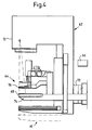
- FIG. 3 shows a lateral view of a first embodiment of the biopsy system 40 according to the present invention.
- the illustrated biopsy system 40 is intended for digital stereotaxy for examination and specimen collection from suspicious areas displaying tissue changes, particularly in the female breast.
- the biopsy system 40 comprises a mammography apparatus 42, a biopsy apparatus 44 and a calculation unit 46 for stereotactic determination of the location of a suspected tumor or suspicious area.
- the biopsy system 40 also contains an image-generating unit 48 consisting of a CCD system (charge-coupled device) or some other digital technology.
- the calculation unit 46 and CCD system 48 are physically part of the same unit.
- the biopsy apparatus 44 is a separate unit, which can be connected to the mammography apparatus 42, and contains, in the illustrated example, both the calculation unit 46 and CCD system 48.
- the mammography apparatus 42 is a conventional mammography apparatus and contains an X-ray tube 50 which can be rotated around an axis 52.
- the biopsy apparatus 44 also contains an arm 54 on which a cassette holder for the CCD system 48 and the calculation unit 46 are arranged.
- the biopsy apparatus 44 further contains a compression plate 56 arranged above the arm 54.
- the said compression plate 56 is vertically movable and has a opening, e.g. 50 x 40 mm, to permit the insertion of e.g. a biopsy needle into a breast (not shown) compressed by the compression plate 56 and arm 54. Dashed lines indicate the path of the beam from the X-ray-emitting tube 50.
- the calculation unit 46 is devised to modify at least one calculation algorithm for the biopsy system 40 on the basis of stereotactic images of a phantom according to the present invention (cf. FIGS. 1-2). Modification may be necessary especially in conjunction with fabrication, installation and service.
- a phantom 10 is accordingly placed in a specific position on the object table (corresponding to the arm 54 and CCD system 48 in the example shown in FIG. 3).
- the exact position of the phantom 10 on the object table 48, 54 can be determined with a vertical radiograph taken immediately above the phantom 10, and the position can be related to the CCD system's 48 image area.
- An alternative to this is to place the phantom 10 against a stop or the like arranged on the object table in such a way that the starting point is fully known.
- the phantom 10 When the phantom 10 has been placed in the specific position on the object table 48, the phantom 10 is irradiated by the X-ray tube 50 from two angles on either side of a centerline perpendicular to the image plane, so two radiographs are obtained.
- the calculation unit 46 modifies the calculation algorithm, according to image information and the known positions of the markers 14 in the phantom 10, in such a way that the calculation algorithm supplies the exact positions.
- the calculation unit 46 employs the exact marker positions and information in images of the phantom 10 to modify the calculation algorithms used in stereotactic biopsy for establishing the x, y, z coordinates for a cell or tissue-sampling area. This means that each stereotactic biopsy system receives individually calibrated calculation algorithms, thereby ensuring accuracy and simplifying installation.
- the system can then be put into service.
- a patient's breast is placed in the compressed state in the biopsy system 40 in the known manner.
- the breast is then irradiated by the X-ray tube 50 from two angles on either side of a centerline perpendicular to the image plane, so two images are obtained.
- These two images are detected by the image-generating unit, i.e. the CCD system 48.
- the calculation unit 46 uses the modified calculation algorithm and information in images of the breast to determine the x, y, z coordinates of the cell or tissue-sampling area. These x, y, z coordinates are subsequently employed for inserting a biopsy needle into a cell or tissue-sampling area and obtaining a tissue specimen.
- the biopsy apparatus 44 incorporates e.g. the calculation unit 46 and the CCD system 48.
- the calculation unit 46 and CCD system 48 can be physically separate units.
- the calculation unit 46 can e.g. consist of software run on e.g. a personal computer connected to the mammography apparatus 42.
- An additional advantage of the CCD system 48 is that it can be devised to fit into a cassette holder intended for a conventional film cassette. This means that an "old" biopsy system can be easily modified.
- FIG. 4 shows a lateral view of a second embodiment of the biopsy system 60 according to the present invention.
- the illustrated biopsy system 60 is intended for stereotaxy with film for examination of the breast, the female breast in particular.
- the biopsy system 60 comprises a mammography apparatus 62, a biopsy apparatus 64 and a calculation unit 66 for stereotactic calculation of the position of a cell or tissue-sampling area.
- the calculation unit 66 is a separate apparatus.
- the biopsy system 60 also contains an image-generating unit 68 consisting of a film cassette 68.
- the mammography apparatus 62 is a conventional mammography apparatus and contains an X-ray tube 70 which rotates around an axis 72.
- the biopsy apparatus 74 comprises an arm 74 on which a cassette holder for a film cassette 68 is arranged.
- the biopsy apparatus 64 further contains a compression plate 76 arranged above the arm 74.
- the said compression plate 76 is vertically movable and has a opening, e.g. 50 x 40 mm, to permit insertion of e.g. a biopsy needle into a breast (not shown) compressed by the compression plate 76 and arm 74.
- Modification of the calculation algorithm in the biopsy system 60 according to the present invention is performed in essentially the same way as described for FIG. 3.
- image registration is with a film cassette supplying ordinary radiographs. This means exposed film is fixed in the calculation unit 66, and the calculation unit 66 then modifies the calculation algorithms used in determining the x, y, z coordinates of a cell or tissue-sampling area in stereotactic biopsy.
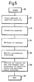
- FIG. 5 is a flow chart showing a method, according to the present invention, for modifying at least one calculation algorithm in a biopsy system, said calculation algorithm having an influence on determination of the position of cell or tissue-sampling areas in stereotactic biopsy when the system is used.
- the method starts in block 90.
- a phantom made of a stable radiotransparent material in which a specific number of radiopaque markers are arranged at known, predefined positions, is then placed in a specific position on an object table.
- the phantom is irradiated from two angles to yield two images.
- the method continues in block 96 when the markers are manually or automatically marked.
- the calculation algorithm is modified in block 98.
- block 100 new radiographs are taken, and the modified calculation algorithm is checked. New modifications may then be made until the most recently modified algorithm identifies the exact position of the markers.
- the method is then concluded in block 102.
Abstract
Description
- A phantom, made of a stable radiotransparent material in which a specific number of radiopaque markers are arranged at known, predetermined positions, is placed in a specific position on an object table;
- The phantom is irradiated from at least two angles of beam so at least two images are obtained; and
- the calculation algorithm is modified on the basis of the known positions of the markers and information in the images.
Claims (5)
- A method for determining at least one calculation algorithm in a biopsy system (40; 60), said calculation algorithm having an influence on determination of the position of cell or tissue-sampling areas in stereotactic biopsy, characterized in thata phantom (10), made of a stable radiotransparent material in which a specific number of radiopaque markers (14) are arranged in known, predefined positions, is placed in a specific position on an object table;the phantom (10) is irradiated from two angles so two images are obtained; andthe calculation algorithm is modified on the basis of information on the known positions of the markers (14) and on image information.
- The method according to patent claim 1, characterized in that the specific position of the phantom (10) on the object table is determined with a vertical radiograph taken immediately above the phantom (10).
- A biopsy system (40; 60) for examining the breast, the female breast in particular, comprising a mammography apparatus (42; 62), a biopsy apparatus (44; 64) and a calculation unit (46; 66) for stereotactic calculation of the position of a cell or tissue-sampling area, characterized in that the calculation unit (46; 66) is devised to modify at least one calculation algorithm on the basis of stereotactic images of a phantom (10) made of a stable, radiotransparent material in which a specific number of radiopaque markers (14) are arranged at known, predefined positions.
- The biopsy system (40; 60) according to claim 3, characterized in that the calculation unit (46; 66) is devised to use the modified calculation algorithm for calculating the position of cell or tissue-sampling areas in stereotactic biopsies.
- The biopsy system (40) according to claims 3-4, characterized in that the biopsy system (40) additionally contains an image-generating unit (48) consisting of a CCD system (48) or some other digital image-generating system.
Applications Claiming Priority (2)
| Application Number | Priority Date | Filing Date | Title |
|---|---|---|---|
| SE9700117 | 1997-01-17 | ||
| SE9700117A SE9700117D0 (en) | 1997-01-17 | 1997-01-17 | A method for modifying at least one computational algorithm for a biopsy system and a biopsy system |
Publications (2)
| Publication Number | Publication Date |
|---|---|
| EP0853920A2 true EP0853920A2 (en) | 1998-07-22 |
| EP0853920A3 EP0853920A3 (en) | 2000-03-01 |
Family
ID=20405440
Family Applications (1)
| Application Number | Title | Priority Date | Filing Date |
|---|---|---|---|
| EP97120564A Ceased EP0853920A3 (en) | 1997-01-17 | 1997-11-24 | A method for modifying at least one calculation algorithm in a biopsy system and a biopsy system |
Country Status (4)
| Country | Link |
|---|---|
| US (1) | US5964715A (en) |
| EP (1) | EP0853920A3 (en) |
| JP (1) | JPH10201749A (en) |
| SE (1) | SE9700117D0 (en) |
Cited By (3)
| Publication number | Priority date | Publication date | Assignee | Title |
|---|---|---|---|---|
| WO2000061024A1 (en) * | 1999-04-08 | 2000-10-19 | Deutsches Krebsforschungszentrum Stiftung des öffentlichen Rechts | Stereotactic localisation method and measuring phantom for a medical application |
| WO2001010299A1 (en) * | 1999-08-09 | 2001-02-15 | University Of British Columbia | Method and automated system for creating volumetric data sets |
| EP2156790A1 (en) | 2008-08-22 | 2010-02-24 | BrainLAB AG | Allocation of x-ray markers to picture markers depicted in an x-ray picture |
Families Citing this family (27)
| Publication number | Priority date | Publication date | Assignee | Title |
|---|---|---|---|---|
| WO2000058691A1 (en) * | 1999-03-18 | 2000-10-05 | Eisenlohr Technologies, Inc. | Radiographic reference marker |
| US6616660B1 (en) * | 1999-10-05 | 2003-09-09 | Sherwood Services Ag | Multi-port side-fire coagulator |
| US6475217B1 (en) * | 1999-10-05 | 2002-11-05 | Sherwood Services Ag | Articulating ionizable gas coagulator |
| FR2822273B1 (en) * | 2001-03-13 | 2003-07-11 | Ge Med Sys Global Tech Co Llc | CALIBRATION PROCESS FOR THE RECONSTRUCTION OF THREE-DIMENSIONAL MODELS FROM IMAGES OBTAINED BY TOMOGRAPHY |
| FR2823969B1 (en) * | 2001-04-30 | 2003-12-26 | Ge Med Sys Global Tech Co Llc | METHOD FOR TAKING TISSUE DURING X-RAY EXAMINATION AND IMPLEMENTING DEVICE |
| AU2002332758A1 (en) * | 2001-08-31 | 2003-03-18 | Analogic Corporation | Image positioning method and system for tomosynthesis in a digital x-ray radiography system |
| US7277833B2 (en) * | 2002-02-06 | 2007-10-02 | Siemens Corporate Research, Inc. | Modeling of the workspace and active pending behavior of an endscope using filter functions |
| DE10353611B4 (en) * | 2003-11-17 | 2013-01-17 | Siemens Aktiengesellschaft | X-ray diagnostic device for mammography examinations |
| EP1750584B1 (en) * | 2004-05-14 | 2020-10-14 | Philips Intellectual Property & Standards GmbH | System and method for diagnosing breast cancer |
| JP4512833B2 (en) * | 2004-12-21 | 2010-07-28 | 国立大学法人群馬大学 | Intra-object site measurement system, intra-object site measurement computing device, in-object site measurement program, and computer-readable recording medium recording the program |
| WO2007095330A2 (en) * | 2006-02-15 | 2007-08-23 | Hologic Inc | Breast biopsy and needle localization using tomosynthesis systems |
| JP2010075316A (en) * | 2008-09-25 | 2010-04-08 | Fujifilm Corp | Stereo biopsy apparatus with automatic calibration function, and method for controlling the same |
| JP2010075317A (en) * | 2008-09-25 | 2010-04-08 | Fujifilm Corp | Stereo biopsy apparatus, method for controlling the same and phantom |
| JP5259346B2 (en) * | 2008-11-05 | 2013-08-07 | 富士フイルム株式会社 | Biopsy equipment |
| JP5373450B2 (en) * | 2009-03-31 | 2013-12-18 | 富士フイルム株式会社 | Biopsy device and method of operating biopsy device |
| JP5355271B2 (en) * | 2009-07-24 | 2013-11-27 | 富士フイルム株式会社 | Radiation imaging equipment |
| JP5507181B2 (en) * | 2009-09-29 | 2014-05-28 | 富士フイルム株式会社 | Radiographic imaging apparatus and method of operating radiographic imaging apparatus |
| JP5421738B2 (en) * | 2009-11-17 | 2014-02-19 | 富士フイルム株式会社 | Biopsy phantom |
| JP2012055549A (en) * | 2010-09-10 | 2012-03-22 | Fujifilm Corp | Phantom for biopsy |
| JP5087124B2 (en) | 2010-10-18 | 2012-11-28 | 富士フイルム株式会社 | Biopsy device, spatial range measurement device, and spatial range measurement method |
| US20120143083A1 (en) * | 2010-12-01 | 2012-06-07 | Andrew Kwai | Devices and methods for improving the usability of stereotactic imaging for performing a breast biopsy |
| KR101205891B1 (en) * | 2011-09-26 | 2012-11-28 | 한국과학기술연구원 | Electrode placement device for stereotactic surgery |
| US9526471B2 (en) * | 2014-04-25 | 2016-12-27 | The Phantom Laboratory, Incorporated | Phantom and method for image quality assessment of a digital breast tomosynthesis system |
| KR102393294B1 (en) * | 2014-09-26 | 2022-05-03 | 삼성전자주식회사 | Medical imaging devices and controlling method thereof |
| JP6275030B2 (en) | 2014-12-24 | 2018-02-07 | 富士フイルム株式会社 | Biopsy device and method of operating the same |
| JP6906239B2 (en) * | 2015-12-28 | 2021-07-21 | ザクト ロボティクス リミテッド | Adjustable registration frame |
| EP3421086B1 (en) * | 2017-06-28 | 2020-01-15 | OptiNav Sp. z o.o. | Determination of geometrical information about a medical treatment arrangement comprising a rotatable treatment radiation source unit |
Citations (1)
| Publication number | Priority date | Publication date | Assignee | Title |
|---|---|---|---|---|
| US5240011A (en) | 1991-11-27 | 1993-08-31 | Fischer Imaging Corporation | Motorized biopsy needle positioner |
Family Cites Families (18)
| Publication number | Priority date | Publication date | Assignee | Title |
|---|---|---|---|---|
| SE8306243L (en) * | 1983-11-14 | 1985-05-15 | Cytex Medicinteknik Ab | LOCATION METHODOLOGY |
| US4655716A (en) * | 1985-08-30 | 1987-04-07 | Xerox Corporation | Contoured mammography phantom with skin |
| US4905150A (en) * | 1988-01-18 | 1990-02-27 | Siemens Aktiengesellschaft | X-ray diagnostics installation with mean parenchyma dose calculator |
| JPH03176041A (en) * | 1989-09-12 | 1991-07-31 | Toshiba Corp | Apparatus and method for calculating coordinate data |
| US5095499A (en) * | 1989-10-05 | 1992-03-10 | Wentz Virginia R | Oriented mammography phantom |
| US5415169A (en) * | 1989-11-21 | 1995-05-16 | Fischer Imaging Corporation | Motorized mammographic biopsy apparatus |
| US5078142A (en) * | 1989-11-21 | 1992-01-07 | Fischer Imaging Corporation | Precision mammographic needle biopsy system |
| US5279309A (en) * | 1991-06-13 | 1994-01-18 | International Business Machines Corporation | Signaling device and method for monitoring positions in a surgical operation |
| US5359637A (en) * | 1992-04-28 | 1994-10-25 | Wake Forest University | Self-calibrated tomosynthetic, radiographic-imaging system, method, and device |
| US5273435B1 (en) * | 1992-07-16 | 1995-12-05 | Wisconsin Med College Inc | Tumor localization phantom |
| US5260985A (en) * | 1992-08-14 | 1993-11-09 | Mosby Richard A | Conforming localization/biopsy grid and control apparatus |
| FR2700909B1 (en) * | 1993-01-27 | 1995-03-17 | Gen Electric Cgr | Device and automatic method for geometric calibration of an X-ray imaging system. |
| US5584292A (en) * | 1994-10-31 | 1996-12-17 | Grumman Aerospace Corporation | Digital X-ray camera for precision mammographic needle biopsy system |
| US5712890A (en) * | 1994-11-23 | 1998-01-27 | Thermotrex Corp. | Full breast digital mammography device |
| US5805665A (en) * | 1995-06-05 | 1998-09-08 | Nelson; Robert S. | Anthropomorphic mammography phantoms |
| US5719916A (en) * | 1995-06-05 | 1998-02-17 | Nelson; Robert S. | Anthropomorphic mammography and lung phantoms |
| US5565678A (en) * | 1995-06-06 | 1996-10-15 | Lumisys, Inc. | Radiographic image quality assessment utilizing a stepped calibration target |
| US5844242A (en) * | 1996-01-26 | 1998-12-01 | The United States Of America As Represented By The Administrator Of The National Aeronautics And Space Administration | Digital mammography with a mosaic of CCD arrays |
-
1997
- 1997-01-17 SE SE9700117A patent/SE9700117D0/en unknown
- 1997-11-24 EP EP97120564A patent/EP0853920A3/en not_active Ceased
-
1998
- 1998-01-02 US US09/002,376 patent/US5964715A/en not_active Expired - Fee Related
- 1998-01-19 JP JP10007805A patent/JPH10201749A/en active Pending
Patent Citations (1)
| Publication number | Priority date | Publication date | Assignee | Title |
|---|---|---|---|---|
| US5240011A (en) | 1991-11-27 | 1993-08-31 | Fischer Imaging Corporation | Motorized biopsy needle positioner |
Cited By (6)
| Publication number | Priority date | Publication date | Assignee | Title |
|---|---|---|---|---|
| WO2000061024A1 (en) * | 1999-04-08 | 2000-10-19 | Deutsches Krebsforschungszentrum Stiftung des öffentlichen Rechts | Stereotactic localisation method and measuring phantom for a medical application |
| WO2001010299A1 (en) * | 1999-08-09 | 2001-02-15 | University Of British Columbia | Method and automated system for creating volumetric data sets |
| US6826313B2 (en) | 1999-08-09 | 2004-11-30 | The University Of British Columbia | Method and automated system for creating volumetric data sets |
| EP2156790A1 (en) | 2008-08-22 | 2010-02-24 | BrainLAB AG | Allocation of x-ray markers to picture markers depicted in an x-ray picture |
| EP2245986A1 (en) * | 2008-08-22 | 2010-11-03 | BrainLAB AG | Arrangement of x-ray markers in the form of a pyramid |
| US8104958B2 (en) | 2008-08-22 | 2012-01-31 | Brainlab Ag | Assigning X-ray markers to image markers imaged in the X-ray image |
Also Published As
| Publication number | Publication date |
|---|---|
| EP0853920A3 (en) | 2000-03-01 |
| SE9700117D0 (en) | 1997-01-17 |
| JPH10201749A (en) | 1998-08-04 |
| US5964715A (en) | 1999-10-12 |
Similar Documents
| Publication | Publication Date | Title |
|---|---|---|
| US5964715A (en) | Method for modifying at least one calculation algorithm in a biopsy system, and biopsy system operating according to the method | |
| US4930143A (en) | Method and device for mammographic stereotactic punction of pathological lesions in the female breast | |
| US10485491B2 (en) | Cone beam CT imaging and image-guided procedures | |
| US5078142A (en) | Precision mammographic needle biopsy system | |
| Bolmgren et al. | Stereotaxic instrument for needle biopsy of the mamma | |
| US4875478A (en) | Portable compression grid & needle holder | |
| US7873198B2 (en) | Methods and apparatus for determining proportions of body materials | |
| US7798710B1 (en) | Mobile radiography system and grid alignment | |
| EP1278458B1 (en) | Fluoroscopic tracking and visualization system | |
| US5260985A (en) | Conforming localization/biopsy grid and control apparatus | |
| US5002735A (en) | Tissue analysis device | |
| US5539797A (en) | Method and apparatus for digital stereotaxic mammography | |
| CA1238723A (en) | Method of x-ray localization | |
| US5107843A (en) | Method and apparatus for thin needle biopsy in connection with mammography | |
| KR101546560B1 (en) | Fiducial marker and method for gamma guided stereotactic localization | |
| US6267502B1 (en) | Alignment verification device and method of using the same with a visual light beam and an x-ray | |
| US6671349B1 (en) | Tomosynthesis system and registration method | |
| JP5329662B2 (en) | Gamma guided stereotactic localization system | |
| US7035450B1 (en) | Method for locating an element of interest contained in a three-dimensional object, in particular during a stereotactic investigation in the X-ray examination of the breast | |
| US6261299B1 (en) | Stereotactic apparatus and methods | |
| US5544219A (en) | Procedure for automatic position-finding of points of interest during a mammography examination using stereotactic technique | |
| RU2204944C2 (en) | Method and device for making mammographic examination and taking puncture biopsy of the mammary gland | |
| Champ et al. | A perspex grid for localization of non‐palpable mammographic lesions in breast biopsies | |
| Alto | Geomatics for precise 3D breast imaging |
Legal Events
| Date | Code | Title | Description |
|---|---|---|---|
| PUAI | Public reference made under article 153(3) epc to a published international application that has entered the european phase |
Free format text: ORIGINAL CODE: 0009012 |
|
| AK | Designated contracting states |
Kind code of ref document: A2 Designated state(s): DE FI FR IT |
|
| AX | Request for extension of the european patent |
Free format text: AL;LT;LV;MK;RO;SI |
|
| PUAL | Search report despatched |
Free format text: ORIGINAL CODE: 0009013 |
|
| AK | Designated contracting states |
Kind code of ref document: A3 Designated state(s): AT BE CH DE DK ES FI FR GB GR IE IT LI LU MC NL PT SE |
|
| AX | Request for extension of the european patent |
Free format text: AL;LT;LV;MK;RO;SI |
|
| RIC1 | Information provided on ipc code assigned before grant |
Free format text: 7A 61B 19/00 A |
|
| AKX | Designation fees paid |
Free format text: DE FI FR IT |
|
| 17P | Request for examination filed |
Effective date: 20001122 |
|
| 17Q | First examination report despatched |
Effective date: 20021004 |
|
| RAP1 | Party data changed (applicant data changed or rights of an application transferred) |
Owner name: SIEMENS AKTIENGESELLSCHAFT |
|
| STAA | Information on the status of an ep patent application or granted ep patent |
Free format text: STATUS: THE APPLICATION HAS BEEN REFUSED |
|
| 18R | Application refused |
Effective date: 20050102 |