The present invention relates to a laser survey
instrument, by which it is possible to form a measurement
plane, in particular an arbitrary tilt setting plane
tilted by a given angle with respect to a horizontal
reference plane in addition to a horizontal reference
plane, by using a laser beam.
In order to obtain a horizontal reference level for a
wide range, a laser survey instrument is used to replace
an optical levelling device.
Using the laser survey instrument, it is possible to
easily obtain a horizontal reference plane by rotary
irradiation of a laser beam in a horizontal direction and
to obtain a horizontal reference line by irradiating a
laser beam on to a wall or the like. Instruments of this
type have been widely used as the means to obtain a
reference level.
Both visible light and invisible light are used as
the irradiating laser beam. When visible light is used,
visibility
is inferior under sunlight, and it is mostly used for
indoor applications such as positioning of window frames
or ceiling assembly during construction or reconstruction
of a building. When invisible light is used, a
photoelectric conversion photodetector is employed on the
light receiving side, and the laser survey instrument can
be used for both indoor and outdoor applications. In
outdoor applications, it is used to form a reference plane
for foundations of buildings or for ground levelling work.
In recent years, tilted ceilings are designed in many
new buildings and a tilted reference plane or a tilted
reference line is required for setting-out operation, for
example, to mount indoor lights to suit the ceiling
surface or to install a handrail along a staircase.
However, the conventional laser survey instrument as
described above is primarily designed to form a horizontal
reference plane or a horizontal reference line, and a
tilted reference plane or a tilted reference line cannot
be easily formed. For this reason, the conventional
instrument is not
suitable for outdoor work or indoor interior work of a
building having a tilted portion. At present, it is not
possible to provide high working accuracy when mounting
indoor lights to suit a ceiling surface or installing a
handrail along a staircase as described above, and there
is a strong need for a laser survey instrument which can
easily perform tilt settings and obtain a tilted reference
plane and a tilted reference line.
It is an object of the present invention to provide a
laser survey instrument which can easily form a tilted
reference plane and a tilted reference line.
According to the present invention, there is provided
a laser survey instrument as specified in claim 1. Some
preferred features are specified in the dependent claims.
To attain the above object, the laser survey
instrument comprises a rotary irradiation system main unit
and an object reflector, wherein said rotary irradiation
system main unit has a light emitter for emitting a laser
beam, a rotator for rotating and irradiating a laser beam,
setting means for scanning a laser beam from said rotator
reciprocally around a predetermined direction, a tilt
setting unit for tilting a rotary irradiation plane of a
laser beam, detecting means for detecting a reflection
light beam entering said rotary irradiation system main
unit via said rotator and reflected from said object
reflector, a reflection light detecting circuit for
identifying a position of said object reflector from
output of said detecting means, and a control unit for
controlling said tilt setting unit to direct a laser beam
toward a predetermined position of said object reflector
based on the detection of said reflection light detecting
circuit, and said object reflector has at least one
reflection sector designed in shape to discriminate the
scanning position of a laser beam.
Preferably, a tilting direction set by said tilt
setting unit corresponds with said direction set by said
setting means. The laser survey instrument may comprise a
rotary irradiation system main unit and an object
reflector, wherein said object reflector has reflection
sectors divided into two or more, at least one of the
reflection sectors has a reflection surface with a
gradually changing shape,
and said rotary irradiation system main unit comprises a
light emitter for emitting a polarized irradiation light
beam, a rotator for rotating and irradiating the polarized
irradiation light beam toward the object reflector and for
detecting an irradiating direction, a tilt setting unit
for tilting a rotary irradiation plane of the polarized
irradiation light beam, detecting means for detecting a
polarized reflection light beam entering the rotary
irradiation system main unit via said rotator and
reflected from said object reflector, a reflection light
detecting circuit for identifying the object reflector
from output of the detecting means, and a control unit for
tracing said object reflector by operating said tilt
setting unit based on detecting condition of said
reflection light detecting circuit and for tilting the
rotation plane of said polarized irradiation light beam.
The laser survey instrument may further comprise a rotary
irradiation system main unit and an object reflector,
wherein said object reflector has reflection sectors
divided into two or more, at least one of said reflection
sectors is a polarization converting reflection sector,
and at
least one of said reflection sectors has a reflection surface with
shape gradually changing, said rotary irradiation system main
unit comprises a light emitter for emitting a polarized
irradiation light beam, a rotator for rotating and irradiating
the polarized irradiation light beam toward the object reflector
and for detecting an irradiating direction, a tilt setting unit
for tilting a rotary irradiation plane of the polarized
irradiation light beam, a first detecting means for detecting a
direction of polarization different from that of the polarized
irradiation light beam emitted from the rotary irradiation system
among the polarized reflection light beam entering the rotary
irradiation system main unit via said rotator and reflected from
said object reflector, a second detecting means for detecting the
same direction of polarization as that of the polarized
irradiation light beam irradiated from the rotary irradiation
system, and a control unit having a reflection light detecting
circuit for identifying irradiating condition of the polarized
irradiation light beam toward the object reflector by comparing
output of said first detecting means with output of said second
detecting means, for tracing said object reflector by
operating said tilt setting unit based on detecting a
condition of said reflection light detecting circuit and
for tilting the rotation plane of said polarized
irradiation light beam. The polarized irradiation light
beam irradiated from the rotator may be circularly
polarized light. Preferably, a tilting direction of the
tilt setting unit is selected, the polarized irradiation
light beam is irradiated for reciprocal scanning at a
predetermined angle around the selected tilting direction,
said control unit traces the object reflector based on the
detecting condition of the reflection light detecting
circuit and tilts the rotation plane of said polarized
irradiation light beam. Preferably, two tilting
directions can be set by setting another tilting direction
within a predetermined time after the setting of a first
tilting direction.
Preferably, a tilt angle is set by holding the object
reflector for a predetermined duration of time. All of
the reflection sectors of the object reflector may be
polarization maintaining reflection sectors, which reflect
light as a polarized reflection light beam, maintaining
the direction of polarization of the polarized irradiation
light beam. All of the reflection sectors of the object
reflector may be polarization converting reflection
sectors, which reflect light as a polarized reflection
light beam, converting the direction of polarization of
the polarized irradiation light beam. Preferably, at
least one of the reflection sectors of the object
reflector is a polarization converting reflection sector,
which reflects light as a polarized reflection light beam,
converting the direction of polarization of the polarized
irradiation light beam, and at least one of the reflection
sectors is a polarization maintaining reflection
sector, which reflects light as a polarized reflection
light beam, maintaining direction of polarization of the
polarized irradiation light beam.
A laser survey instrument in which the present
invention is embodied will now be described by way of
example only and with reference to the following Figures:
Figures 1 to 3 each represent a mechanical portion of a
rotary irradiation system
main unit 1.
At the centre of a casing 5, a recessed portion 6 in
truncated conical shape is formed, and a support seat 7 is
provided at the center of the recessed portion 6. The
support seat 7 is designed in such a manner that a
projection 9 protruding toward the center with a smooth
tertiary curved surface is formed at each of three equally
divided positions on an inner periphery of a circular
through-hole 8.
A laser projector 10 for emitting a laser beam is
placed into the through-hole 8, and a head 11 of the laser
projector 10 is engaged with and supported by the support
seat 7. The lower portion of the head 11 has a spherical
shape, and a spherical unit 11a thus formed is brought
into contact with each of the three projections 9. The
laser projector 10 can be tiltably supported in any
direction desired with respect to a vertical line or axis.
A motor seat 14 is provided on the head 11, and a scanning
motor 15 is arranged on the motor seat 14. A driving gear 16 is
engaged on an output shaft of the scanning motor 15. The driving
gear 16 is engaged with a scanning gear 17 to be described later.
On the head 11 of the laser projector 10, a mirror holder 13 is
rotatably mounted via a bearing 12 being aligned with an axis of
the laser projector 10. The scanning gear 17 is attached on the
mirror holder 13 and is engaged with the driving gear 16 as
described above so that the mirror holder 13 can be rotated around
the vertical axis by the scanning motor 15. A pentagonal prism
18 is arranged on the mirror holder 13, and a laser beam emitted
from the laser projector 10 is irradiated in a horizontal
direction through a projection window 19. The scanning motor 15,
the driving gear 16, the mirror holder 13, the pentagonal prism
18, etc. constitute a rotator 2.
A first level sensor 20 and a second level sensor 21 for
detecting a horizontal line or plane are provided below the laser
projector 10. At the lower end of the laser projector 10, a
tilting detector 23 is fixed. The tilt detector 23 is designed
in the shape of an inverted cup, and a reflection mirror
flange 22 is arranged on the periphery.
On the bottom of the casing 5 and at positions
opposite to the tilt detector 23, a given number (four in
the present embodiment) of optical sensors 24a, 24b, 24c
and 24d, each comprising a set of light emitting elements
and photodetection elements, is provided on the same
circumference around the axis of the laser projector 10
when the casing 5 and the laser projector 10 are at a
vertical position.
From the head 11 of the laser projector 10, a first
tilting arm 25 and a second tilting arm 26 are extended in
a horizontal direction and perpendicularly to each other.
These are designed to penetrate the conical plane of the
recessed portion 6 and are positioned inside the casing 5.
On a tip of each of the first tilting arm 25 and the
second tilting arm 26 are arranged, engaging pins 27 and
28 respectively. The engaging pins 27 and 28 are
cylindrical, and have axes that cross perpendicular to
each other. The engaging pins 27 and 28 are positioned in
such a manner that these axes are included within a plane,
which passes
through the spherical center of the spherical unit 11a.
For one of the engaging pins 27 and 28, e.g. the engaging
pin 27, movement in a horizontal direction is restricted,
and it can be moved only in a vertical direction.
Although not shown in the figures, the engaging pin 27 is
slidably engaged in a guide groove extending in a vertical
direction, or the engaging pin 27 is slidably pressed
against a wall surface that extends in a vertical
direction via resilient means such as a spring, etc.
On an inner wall of the casing 5, shelf plates 29 and
30 are mounted. A first level adjusting motor 31 is
mounted on the shelf plate 29, and a second level
adjusting motor 32 is mounted on the shelf plate 30. A
first driving gear 33 is engaged on a rotation shaft of
the first level adjusting motor 31, and a second driving
gear 34 is engaged on a rotation shaft of the second level
adjusting motor 32. A first screw shaft 35 running
perpendicularly to the engaging pin 27 and stretched
between the ceiling of the casing 5 and the shelf plate 29
is rotatably arranged. A first driven gear 36 is mounted
on the first screw shaft 35 and is engaged with the first
driving gear 33. The first
screw shaft 35 is screwed into a first slide nut 37, and a pin
38 is protruded from the first slide nut 37. The pin 38 is slidably
abutted on the engaging pin 27.
Similarly, a second screw shaft 39 running perpendicularly
to the engaging pin 28 and stretched between the ceiling of the
casing 5 and the shelf plate 30 are rotatably arranged. A second
driven gear 40 is engaged on the second screw shaft 39 and is
engaged with the second driving gear 34. The second screw shaft
39 is screwed into a second slide nut 41, and a pin 42 is protruded
from the second slide nut 41. The pin 42 is slidably abutted on
the engaging pin 28.
In the ceiling portion of the casing 5, a spring receptacle
43 is arranged between the first screw shaft 35 and the second
screw shaft 39, and a spring 44 is stretched between the spring
receptacle 43 and the laser projector 10 so that the laser
projector 10 is pushed in clockwise direction around the support
seat 7 as shown in Fig. 1.
In the figure 1, reference numeral 45 represents a battery
box to accommodate a battery for driving the laser survey
instrument. The rotary irradiation system main unit 1 is
mounted on a tripod (not shown) via screws 46 for
levelling. Reference numeral 47 represents a glass window
provided on the periphery of the mirror holder 13.
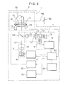
Next, Figure 4 is a block diagram that shows a
tilting controller.
Detection results of the first level sensor 20 and
the second level sensor 21 are inputted to a first angle
detecting circuit 51 and a second angle detecting circuit
52. On the first angle detecting circuit 51 and the
second angle detecting circuit 52, a reference angle 50
(usually, the reference plane is horizontal and the
reference angle is 0°) is set. Angular deviations are
calculated in the first angle detecting circuit 51 and the
second angle detecting circuit 52 respectively based on
the reference angle 50. The angular deviation thus
calculated is inputted to a first motor controller 53 and
a second motor controller 54 respectively or to a
computation controller 55. The computation controller 55
inputs a control signal such as rotating direction
instruct signal, a speed control signal and a speed
acceleration/deceleration signal, etc. to the first motor
controller 53 and the second motor controller 54. The
first motor controller 53 and the second motor controller
54 drive the first level adjusting motor 31 and the second
level adjusting motor 32 respectively. The computation
controller 55 controls the first level adjusting motor 31
and the second level adjusting motor 32 via the first
motor controller 53 and the second motor controller 54 so
that the deviation of the angular signals from the first
angle detecting circuit 51 and the second angle detecting
circuit 52 is turned to 0.
In the following, a description will be given of the
levelling operation of the laser survey instrument.
When the rotary irradiation system main unit 1 is
installed and is not yet adjusted, the axis of the laser
projector 10 is not aligned with a vertical line, and the
first level sensor 20 and the second level sensor 21 are
not at a horizontal position. When the reference angle 50
is 0°, angular deviation signals are issued from the first
angle detecting circuit 51 and the second angle detecting
circuit 52 to the computation controller 55. When
the angular deviation signals are outputted, the computation
controller 55 drives the first level adjusting motor 31 and the
second level adjusting motor 32 in a desired direction via the
first motor controller 53 and the second motor controller 54 so
that each of the angular deviation signals is turned to 0.
Description will be given on operation of the level
adjusting motors 31 and 32, taking an example on the first level
adjusting motor 31.
When the first level adjusting motor 31 is driven, rotation
of the first level adjusting motor 31 is transmitted to the first
screw shaft 35 via the first driving gear 33 and the first driven
gear 36, and the first slide nut 37 is moved up or down as the
first screw shaft 35 is turned. Upward or downward movement of
the first slide nut 37 is transmitted to the first tilting arm
25 via the pin 38 and the engaging pin 27, and the laser projector
10 is tilted.
As described above, the engaging pin 27 is restricted from
moving in a horizontal direction and can move only in a vertical
direction. For this reason, a tilting direction of the laser
projector 10 is restricted, and it is tilted around the axis of
the engaging pin 28, which runs through the spherical center of
the spherical unit lla. Next, when the second level adjusting
motor 32 is driven, the second screw shaft 39 is turned, and the
engaging pin 28 is moved up or down via the pin 42.
The movement of the engaging pin 27 in a horizontal
direction is restricted by a groove (not shown), and its movement
in a vertical direction is restricted by the pin 38 and the spring
44. As a result, the engaging pin 27 is allowed only to rotate
around the axis of the engaging pin 27, which runs through the
spherical center of the spherical unit 11a. When the pin 42 is
moved up and down, the engaging pin 28 slides in an axial direction
between the engaging pin 28 and the pin 42, and the engaging pin
28 is vertically displaced, and the laser projector 10 is tilted
around the axis of the engaging pin 27. As described above,
cross-section of the engaging pin 27 is in circular shape. Thus,
tilting of the axis of the engaging pin 27 is not changed due to
the rotation of the engaging pin 27. That is, tilting operation
by the level adjusting motors 31 and 32 exerts no influence on
tilting axis of the other, i.e. on tilting of the axes of the
engaging pins 27 and 28. Therefore, tilt adjusting operation of
one axis can be performed independently from tilt adjusting
operation of the other axis, and the tilt adjusting operation and
control sequence relating to the tilt adjusting operation can be
extremely simplified.
Because the laser projector 10 is pushed in clockwise
direction in Fig. 1 by the spring 44, the laser projector 10
accurately follows the movement of the first slide nut 37.
There are provided the optical sensors 24a, 24b, 24c and
24d to prevent the movement of the adjusting mechanism (which
comprises the first level adjusting motor 31, the second level
adjusting motor 32, the first driving gear 33, the second driving
gear 34, the first driven gear 36, the second driven gear 40, the
first screw shaft 35, the second screw shaft 39, the first slide
nut 37, the second slide nut 41, the first tilting arm 25, the
second tilting arm 26, etc.) beyond the mechanical adjustment
range. Specifically, when the limit of the mechanical adjustment
range is reached, light emitted from one of the optical sensors
24a, 24b, 24c or 24d is reflected by the reflection mirror flange
22 and is received by the optical sensor again, and it is detected
that the limit of the mechanical adjustment range has been
reached. Then, the first level adjusting motor 31 and the second
level adjusting motor 32 are stopped, or display is provided on
a display unit (not shown) or alarm such as buzzer is issued to
indicate that the limit of the mechanical adjustment range has
been reached.
Wich regard to tilting operation of the laser projector
10, the laser projector 10 is stably supported because the
spherical unit 11a of the laser projector 10 is supported at 3
points by the projections 9. Because of the contact between
the spherical unit 11a and the projections 9 with smooth curved
surfaces, the laser projector 10 can be tilted in any tilting
direction smoothly and freely, and the posture of the laser
projector 10 can be easily adjusted. Detailed description on the
tilting operation is not given here because it is the same as the
leveling operation described above.
Now, description will be given on optical arrangement and
electrical arrangement of the rotary irradiation system
main unit 1 referring to Figure 6.
In the figure, the same components as in Figure 1 are
referred to by the same symbols. The rotary irradiation
system main unit 1 comprises a light emitter 3, a rotator
2, a reflection light detector 4, a control unit (CPU) 60,
a light emitting element driving unit 61, a motor driving
unit 62, and a control panel 63.
First, the light emitter 3 is described.
On an optical axis of a laser diode or a visible
laser diode 65, which emits a polarized irradiation light
beam of linearly polarized light, a collimator lens 66, a
first λ/4 birefringence member 67, and a perforated mirror
68 are arranged in this order as seen from the laser diode
65. The polarized irradiation light beam of linearly
polarized light emitted from the laser diode 65 is turned
to a parallel beam by the collimator lens 66 and is
converted to circularly polarized light by the first λ/4
birefringence member 67. The circularly polarized
irradiation light beam passes through the perforated
mirror 68 and is irradiated to the rotator 2.
The rotator 2 deflects an optical axis of the polarized
irradiation light beam 100 emitted from the light emitter 3 by
90° and irradiates the light beam for scanning. A pentagonal
prism 18 for deflecting the optical axis of the polarized
irradiation light beam coming from the light emitter 3 is provided
on the mirror holder 13, which is rotated around the optical axis
of the polarized irradiation light beam. The mirror holder 13
is connected to a scanning motor 15 via a scanning gear 17 and
a driving gear 16. The rotating condition of the mirror holder
13 is detected by an encoder 69, and a detection signal of the
encoder 69 is inputted to the control unit (CPU) 60.
The irradiated laser beam from the rotator 2 is reflected
by an object reflector 80, and a polarized reflection light beam
coming from the object reflector 80 enters the rotator 2. After
entering the pentagonal prism 18, the polarized reflection light
beam is deflected toward the perforated mirror 68, and the
polarized reflection light beam enters the reflection light
detector 4 through the perforated mirror 68.
Next, the reflection light detector 4 will be described.
On a reflection optical axis of the perforated mirror
68, a condenser lens 70, a second λ/4 birefringence member
71, a pinhole 72, a polarization beam splitter 73, and a
first photelectric converter 74 are arranged in this order
as seen from the perforated mirror 68, and a second
photoelectric converter 75 is arranged on the reflection
optical axis of the polarization beam splitter 73.
Outputs from the first photoelectic converter 74 and the
second photoelectic converter 75 are inputted to a
reflection light detecting circuit 76.
The polarization beam splitter 73 splits the
polarized reflection light beam entering the reflection
light detector 4 and the light beam enters the first
photoelectric converter 74 and the second photelectric
converter 75. The second λ/4 birefingence member 71
and the polarization beam splitter 73 are arranged in
such manner that the polarized irradiation light beam,
emitted from the light emitter 3 and having the same
direction of polarization as that of the polarized
reflection beam returning to the main unit after passing
through the λ/4 birefringence member twice, is irradiated
to the first
photoelectric converter 74, and the polarized irradiation
light beam emitted from the light emitter 3 and having the
same direction of polarization as the polarized
irradiation light beam is irradiated to the second
photoelectric converter 75.
Next, description will be given on the control unit
(CPU) 60.
Instructions from an operator are inputted to the
control unit (CPU) 60, via the control panel 63. Signals
from the encoder 69 and the reflection light detector 4
are also inputted to the CPU 60. The position of the
object reflector 80 and widths of a polarization
converting reflection sector (to be described later) and a
reflection layer (to be described later) of the object
reflector 80 are detected, and rotation of the rotator 2
is controlled via the motor driving unit 62. Based on the
relationship between the widths of the polarization
converting reflection sector (to be described later) and
the reflection layer (to be described later) of the object
reflector 80, the position on the object reflector 80
which is scanned is detected by the polarized irradiation
light beam, and it is given as a scanning position signal.
Based on the
detected position, the signal from the control unit 60 is inputted
to the computation controller 55, which drives in turn the level
adjusting motors 31 and 32 via the motor controllers 53 and 54.
The light emitting condition of the laser diode 65 is controlled
according to the rotating condition of the rotator 2 via the light
emitting element driving unit 61.
Next, description will be given on the light emitting
element driving unit 61.
The light emitting element driving unit 61 obtains a clock
signal for pulse modulation from the reflection light detecting
circuit 76 and performs pulse modulation of the polarized
irradiation light beam emitted from the laser diode 65. This
pulse modulation makes it possible to easily amplify the
photodetection signal and to decrease noise level.
Next, description will be given on the motor driving unit
62.
The motor driving unit 62 controls rotation of the scanning
motor 15 of the rotator 2 based on a rotating direction signal
from the control unit 60 and controls scanning of the polarized
irradiation light beam.
Next, description will be given on the control panel 63
referring to Fig. 5.
The control panel 63 comprises tilting direction setting
buttons 90a, 90b, 90c, and 90d for setting a tilting direction
(an irradiating direction of the laser beam for reciprocal
scanning at a desired angle), stop mode buttons 91a and 91b for
fixing an irradiating direction of the laser beam and for setting
it to stop mode for step feeding, rotary scanning speed setting
buttons 92a and 92b, a power source button 93, a photodetector
setting button 94, which switches the rotary scanning speed of
the laser beam between the case where a photodetector is used and
the case where a visual check is performed because the rotary
scanning speed is different in both of the cases, and a manual
button 95 for selecting automatic leveling or manual adjustment
of the system. The setting status by the tilting direction
setting buttons 90a, 90b, 90c and 90d is displayed by a light
emitting diode 96, battery consumption status of the rotary
irradiation system main unit 1 is displayed by a light emitting
diode 97, selecting status of the photodetector by the
photodetector setting button 94 is displayed by a light emitting
diode 98, and automatic or manual selection status of the manual
button 95 is displayed by a light emitting diode 99.
In the following, description will be given on optical and
electrical operation of the rotary irradiation system main unit
1 and on a method to detect the object reflector 80.
The polarized irradiation light beam emitted from the
laser diode 65, which is driven by the light emitting element
driving unit 61, is modulated according to the clock signal from
an oscillator (not shown). The linearly polarized irradiation
light beam emitted from the laser diode 65 is turned to parallel
beam by the collimator lens 66. Further, it is turned to
circularly polarized irradiation light beam after passing
through the first λ/4 birefringence member 67. The circularly
polarized irradiation light beam passes through the perforated
mirror 68 and is deflected by an angle of 90° through the
pentagonal prism 18 and is irradiated from the rotary irradiation
system main unit 1.
The pentagonal prism 18 is rotated by the scanning motor
15 via the driving gear 16 and the scanning gear 17. At first,
the pentagonal prism 18 is rotated by total circumferential
rotation, and the polarized irradiation light beam coming through
the pentagonal prism 18 is irradiated for total circumferential
scanning.
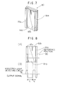
Next, description will be given on the object reflector
80, referring to Fig. 7, Fig. 8 (A) and Fig. 8 (B).
On the object reflector 80, a λ/4 birefringence member in
form of oblong tablet is attached along the left edge to form a
polarization converting reflection sector 85a. A λ/4
birefringence member of inverted triangular shape is attached at
a position opposite to the polarization converting reflection
sector 85a to have a reflection layer (polarization maintaining
reflection sector) 84b in erected triangular shape therebetween,
thus forming a polarization converting reflection sector 85b.
Further, a reflection layer (polarization maintaining reflection
sector) 84a of oblong tablet shape is provided along the right
edge.
As described above, the object reflector 80 comprises
polarization maintaining reflection sectors 84a and 84b and
polarization converting reflection sectors 85a and 85b. The
polarization reflection light beam reflected by the polarization
maintaining reflection sectors 84a and 84b is circularly
polarized light where polarization status of the incident
polarized irradiation light beam is maintained, and the polarized
reflection light beam reflected by the polarization converting
reflection sectors 85a and 85b is circularly polarized light
having phase deviated by λ/2 with respect to the polarization
status of the incident polarized irradiation light beam.
The polarized reflection light beam reflected by the
object reflector 80 and entering the rotator 2 is deflected by
an angle of 90° by the pentagonal prism 18 and enters the
perforated mirror 68, and the perforated mirror 68 irradiates the
reflection light beam toward the condenser lens 70. The condenser
lens 70 irradiates the reflection light beam as convergent light
toward the second λ/4 birefringence member 71, and the polarized
reflection light beam, returning as circularly polarized light,
is converted to linearly polarized light by the second λ/4
birefringence member 71 and enters the pinhole 72. As described
above, the polarized reflection light beam reflected by the
polarization maintaining reflection sectors 84a and 84b has its
phase by λ/2 different from the phase of the polarized reflection
light beam reflected by the polarization converting reflection
sectors 85a and 85b. As a result, plane of polarization differs
by 90° between the two polarized reflection light beams, which
have been converted to linearly polarized light by the second λ/4
birefringence member 71.
For the reflection light beam, which has an optical axis
deviated from that of the polarized irradiation light beam
irradiated from the main unit and is not properly directed to the
polarized reflection light beam, i.e. the reflection light beam
from unnecessary reflector other than the object reflector 80,
the pinhole 72 plays a role to prevent this reflection light beam
from entering the first photoelectric converter 74 and the second
photoelectric converter 75. After passing through the pinhole
72, the polarized reflection light beam enters the polarization
beam splitter 73.
The polarization beam splitter 73 splits the light beam
into polarized components, which run perpendicularly to each
other. It allows the polarized reflection light beam to pass,
which is the same as (but having direction of polarization varied
by 180° from) the polarized irradiation light beam emitted from
the laser diode 65 and reflects the polarized reflection light
beam, which has direction of polarization by 90° different from
that of the polarized irradiation light beam emitted from the
laser diode 65. Both the first photoelectric converter 74 and
the second photoelectric converter 75 receive the polarized
reflection light beam thus split.
The first photoelectric converter 74 and the second
photoelectric converter 75 are designed to have the following
photodetecting conditions: When the polarized reflection light
beam reflected by the polarization converting reflection sectors
85a and 85b of the object reflector 80 enters the reflection light
detector 4, it is designed in such manner that the amount of light
entering the first photoelectric converter 74 is more than the
amount of light entering the second photoelectric
converter 75 because of the relationship between the
second λ/4 birefringence member 71 and the polarization
beam splitter 73, and that when the polarized reflection
light beam reflected by the polarization maintaining
reflection sectors 84a and 84b of the object reflector 80
enters the reflection light detector 4, the amount of
light entering the second photoelectric converteer 75 is
more than the amount of light entering the first
photoelectric converter 74.
When the object reflector 80 is scanned by a laser
beam, an output signal from the reflection light detecting
circuit 76 is as shown in Figure 8 (B). By detecting a
point where widths (durations) t1 and t2 of the output
signals agree with each other, ther center of the object
reflector 80 can be detected. In the output signal,
signal waveform is asymmetrical. Therefore, even when the
laser beam scans the center of the object relfector 80,
the scanning direction of the laser beam can be identified
only from the output signal from the reflection light
detecting circuit 76.
Normally, when a reflection laser beam from the
object
reflector is received, it is not that photodetection
signal rises up at the time of detection but it rises up
with an inclination with some ambiguity just as the fact
that the center of the spot light of the reflected laser
beam is brighter. In the object reflector 80 as shown in
Figure 7, the polarization maintaining reflection sector
84a and the polarization converting reflection sector 85a,
each in the form of an oblong tablet, are formed on the
edges of the polarization maintaining reflection sector
84b and the polarization converting reflection sector 85b,
which are each triangular in shape. Thus, the transfer
point of the photodetection signal can be easily
identified, and the central position can be detected with
high accuracy. Because a vertical direction can be
identified from the object reflector itself, when the
rotary irradiation system main unit 1 is installed on a
ceiling or a floor etc., it is possible to easily
distinguish reflection light, which is reflected by the
ceiling or floor surface and comes back.
The polarization maintaining reflection sector 84b
and the polarization converting reflection sector 85b in
inverted
triangular shape make it possible to easily identify the central
position of the object reflector 80, while these reflection
sectors may be designed in V-shape or inverted V-shape. In
addition, there is no restriction on the shape so far as the width
is varied in a vertical direction and the central position can
be detected from the change in width.
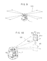
Next, description will be given on tilt setting operation
by the laser survey instrument referring to Fig. 9 to Fig. 13.
The rotary irradiation system main unit 1 is installed,
as shown in Fig. 11, for example, on upper portion of wall of a
building 101 near ceiling 102 via a mounting stand 104. The
mounting stand 104 has a clamp 105. For example, by clamping a
beam 103 on wall surface using the clamp 105, the mounting stand
104 can be fixed on the wall surface. The mounting stand 104 has
an elevating table 106, which can be moved up or down to adjust
the vertical position of the stand. The rotary irradiation system
main unit 1 is fixed on the elevating table 106 using fixing means
such as bolt.
After fixing the main unit at a predetermined position,
the power source button 93 on the control panel 63 is pressed,
and the rotary irradiation system main unit 1 is started to
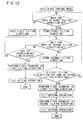
operate. In the following, description will be given on the
operation referring to Fig. 12 and Fig. 13.
The rotary irradiation system main unit 1 starts to perform
the leveling operation as described above. It is operated in such
manner that the polarized irradiation light beam 100 can be
irradiated in a horizontal direction, and the polarized
irradiation light beam 100 is rotated and irradiated in a
horizontal direction. One of the tilting direction setting
buttons 90a, 90b, 90c and 90d is pressed to set a first tilting
direction. The first tilting direction thus set is stored in
memory in the control unit 60. In case the second tilting
direction is not set within a predetermined time after the setting
of the first tilting direction, the polarized irradiation light
beam 100 is irradiated toward the first tilting direction, and
reciprocal scanning in fan-shaped is performed with the preset
scanning angular range. Thus, the setting of tilting direction
is completed.
In case the direction to be tilted does not agree with the
irradiating direction of the polarized irradiation light beam
100, fixed connection of the rotary irradiation system main unit
1 with the elevating table 106 is loosened, and the rotary
irradiation system main unit 1 is rotated as necessary. If
leveling is deviated in this case, the leveling operation should
be repeated.
Using two or more object reflectors 80, or by moving a
single object reflector 80 in a predetermined direction, it is
possible to set two or more tilting directions. In the following,
description will be given on a case where tilting is set in two
directions.
After the first tilting direction has been set, a second
tilting direction is set by operating another tilting direction
setting button within a predetermined time. Then, the second
tilting direction thus set is stored in memory in the control unit
60 just like the first tilting direction. The second tilting
direction is compared with the first tilting direction in the
control unit 60. If both tilting directions agree with each
other, the setting is cancelled. If the second tilting direction
is different from the first tilting direction, tilt setting
operation is performed on each of the tilting directions.
Specifically, the polarized irradiation light beam 100 is
irradiated toward the first tilting direction at first, and
reciprocal scanning is performed within a preset angular scanning
range. By the tilt setting operation, if tl and t2 agree with
each other, the polarized irradiation light beam 100 is
irradiated in the second tilting direction after the
predetermined time. Then, reciprocal scanning is performed
within the preset angular scanning range, and the tilt setting
is performed in the same way. The transfer between the tilt
setting operation of the first tilting direction and the tilt
setting operation of the second tilting direction may be
automatically performed after the predetermined time has
elapsed, or operator may operate button to transfer the
operation.
Description will be given now on the tilt setting operation
referring to Fig. 13.
The operator holds the object reflector 80 by hand and
keeps it in the polarized irradiation light beam 100 so that the
polarized irradiation light beam 100 is irradiated on the object
reflector 80. The polarized irradiation light beam 100 scans
across the object reflector 80 reciprocally, and reflection light
from the object reflector 80 enters the rotary irradiation system
main unit 1, and a photodetection signal from the reflection light
detector 4 is outputted to the control unit 60. The control unit
60 compares tl and t2 according to the photodetection signal and
adjusts the irradiating direction of the polarized irradiation
light beam 100 in a vertical direction to have the result: tl/t2
= 1. In case the object reflector 80 is set in a predetermined
direction, e.g. in case an angle of elevation is to be set, it
is moved up as shown in Fig. 10 and Fig. 11. The rotary irradiation
system main unit 1 forces the polarized irradiation light beam
100 to trace the object reflector 80 and gives an angle of
elevation to it. Angle of elevation or depression of the
polarized irradiation light beam 100 is adjusted by tilting the
laser projector 10, and tilting of the polarized irradiation
light beam 100 based on the determination of the angle of
elevation or depression with respect to a horizontal plane
agrees with the tilting direction of the laser projector
10.
The object reflector 80 is moved toward a position to
be set and is held there for a predetermined time. The
rotary irradiation system main unit 1 is operated in such
a manner that the scanning position of the polarized
irradiation light beam 100 is aligned with the center of
the object reflector 80. When a predetermined time has
elapsed under this condition, it is judged that the tilt
setting has been completed, and even when the object
reflector 80 is removed, tile setting of the polarized
irradiation light beam 100 is maintained at the same
position.
When the setting of tilt and the setting of angle of
elevation or depression of the polarized irradiation light
beam 100 have been completed, the polarized irradiation
light beam 100 forms a reference plane by rotary
irradiation in parallel to the ceiling 102. Based on this
reference plane, an illuminating lamp is mounted, for
example, in a fixed direction from the ceiling.
In case the angle of elevation or depression is already
known, the setting value of angle of elevation or depression is
inputted to a reference angle 50 as shown in Fig. 4 after leveling.
Outputs from the first angle detecting circuit 51 and the second
angle detecting circuit 52 are inputted to the computation
controller 55. The computation controller 55 drives the first
level adjusting motor 31 and the second level adjusting motor 32
via the first motor controller 53 and the second motor controller
54 so that a detection angle from the first angle detecting
circuit 51 and the second angle detecting circuit 52 is turned
to the reference angle 50.
In the object reflector 80 shown in Fig. 7, the
polarization maintaining reflection sectors 84a and 84b may be
reflection surfaces, and the polarization converting reflection
sectors 85a and 85b may be non-reflection surfaces. Also, on the
reflection sector with its shape gradually changing, the width
at the central position is considered as a known value, and if
a comparison value is inputted, there is no need to compare
photodetecting conditions from the two reflection sectors, and
it is possible to detect the center of the object reflector by
comparing the signal width (duration) obtained by the
photodetection signal from one reflection sector with the
comparison value. Further, the computation controller 55 and the
control unit 60 may be replaced with a single control unit, which
has the same functions as these components.
As described above, the
tilting direction can be set by simply pressing the tilting
direction setting button, and the setting of tilt angle can be
completed by simply irradiating the polarized irradiation light
beam on the object reflector and by moving it to a predetermined
position. Accordingly, it is possible to easily set a tilting
reference plane and a tilting reference line by extremely
simplified working procedure.