EP0855845A2 - Interfacing device for ATM networks - Google Patents
Interfacing device for ATM networks Download PDFInfo
- Publication number
- EP0855845A2 EP0855845A2 EP97122923A EP97122923A EP0855845A2 EP 0855845 A2 EP0855845 A2 EP 0855845A2 EP 97122923 A EP97122923 A EP 97122923A EP 97122923 A EP97122923 A EP 97122923A EP 0855845 A2 EP0855845 A2 EP 0855845A2
- Authority
- EP
- European Patent Office
- Prior art keywords
- modules
- atm
- circuit
- cells
- atm network
- Prior art date
- Legal status (The legal status is an assumption and is not a legal conclusion. Google has not performed a legal analysis and makes no representation as to the accuracy of the status listed.)
- Granted
Links
Images


Classifications
-
- H—ELECTRICITY
- H04—ELECTRIC COMMUNICATION TECHNIQUE
- H04Q—SELECTING
- H04Q11/00—Selecting arrangements for multiplex systems
- H04Q11/04—Selecting arrangements for multiplex systems for time-division multiplexing
- H04Q11/0428—Integrated services digital network, i.e. systems for transmission of different types of digitised signals, e.g. speech, data, telecentral, television signals
- H04Q11/0478—Provisions for broadband connections
-
- H—ELECTRICITY
- H04—ELECTRIC COMMUNICATION TECHNIQUE
- H04B—TRANSMISSION
- H04B7/00—Radio transmission systems, i.e. using radiation field
- H04B7/14—Relay systems
- H04B7/15—Active relay systems
- H04B7/185—Space-based or airborne stations; Stations for satellite systems
- H04B7/18578—Satellite systems for providing broadband data service to individual earth stations
- H04B7/18582—Arrangements for data linking, i.e. for data framing, for error recovery, for multiple access
-
- H—ELECTRICITY
- H04—ELECTRIC COMMUNICATION TECHNIQUE
- H04L—TRANSMISSION OF DIGITAL INFORMATION, e.g. TELEGRAPHIC COMMUNICATION
- H04L12/00—Data switching networks
- H04L12/54—Store-and-forward switching systems
- H04L12/56—Packet switching systems
- H04L12/5601—Transfer mode dependent, e.g. ATM
- H04L2012/5629—Admission control
- H04L2012/563—Signalling, e.g. protocols, reference model
-
- H—ELECTRICITY
- H04—ELECTRIC COMMUNICATION TECHNIQUE
- H04L—TRANSMISSION OF DIGITAL INFORMATION, e.g. TELEGRAPHIC COMMUNICATION
- H04L12/00—Data switching networks
- H04L12/54—Store-and-forward switching systems
- H04L12/56—Packet switching systems
- H04L12/5601—Transfer mode dependent, e.g. ATM
- H04L2012/5638—Services, e.g. multimedia, GOS, QOS
- H04L2012/5646—Cell characteristics, e.g. loss, delay, jitter, sequence integrity
- H04L2012/5651—Priority, marking, classes
Definitions
- the present invention relates to a device for interfacing an ATM (Asynchronous Transfer Mode) network with connection lines of the kind commonly known as "connection oriented", such as the lines used for AAL1 (ATM Adaptation Layer 1) services, with fixed bit rate.
- ATM Asynchronous Transfer Mode
- connection oriented such as the lines used for AAL1 (ATM Adaptation Layer 1) services, with fixed bit rate.
- connection oriented lines indicates, as the people skilled in the art know, lines destined to convey signals pertaining to a specific application.
- application is used to indicate an apparatus, a service, a network.
- the present invention has been developed with particular attention to its possible use to interface an ATM network operating at 34 Mbit/s both with conventional telecommunications networks (terrestrial or via satellite), and with terminals offering broad band services (multimedia services).
- Typical examples of the related connection lines are those based on the G.703 interface at 2 Mbit/s and on the RS449 interface with bit rate N ⁇ 64 kbit/s.
- ATM transport techniques have the purpose of enhancing the efficiency of telecommunications networks in terms of flexibility, reconfiguration capability and transport capacity, according to criteria providing for the organisation of the flows transported into so-called cells.
- Such cells are routed within the ATM network according to dynamic schemes able to attain an optimal adaptation of the network exploitation to the transport requirements.
- connection lines of the type mentioned previously In order to transport on an ATM network data flows conveyed over connection lines of the type mentioned previously, until now it has been suggested to create within the ATM network a durable connection (albeit constituted according to the typical operating modes of the ATM network) between the two nodes involved in the transport.
- This connection is maintained, with its preestablished, fixed band, throughout the time interval during which the information flow is transported. This also occurs when the band actually needed for transport is reduced, at least temporarily.
- a connection destined to transit over the network is always allocated 34 Mbit/s even when the transport requirements of the connection are in fact lower.
- the present invention has the purpose of providing an interface device capable of overcoming the drawbacks described above.
- Such a device demonstrates, notably in its currently preferred embodiment, particularly appreciable functional features, especially in relation to the following aspects:
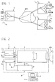
- FIG. 1 shows a plurality of devices according to the invention, each indicated with the reference numeral 1, connected to an ATM network (whose characteristics shall be considered wholly known in the description which follows) in order to allow their interfacing with a plurality of connection lines 2 1 ...2 k ...2 n (where n needs not to be the same for all the devices 1).
- an ATM network whose characteristics shall be considered wholly known in the description which follows
- connection lines 2 k 1,...n
- connection oriented services i.e. each line (or group of lines, which is equivalent) allows interfacing the device with a particular type of application (for instance: video encoder audio encoder satellite connection, etc.).
- An important characteristic of the device according to the invention is that of being organised in two sections or stages, namely, with reference to the diagram in Figure 2, a plurality of adapter modules 3 1 ...3 k ...3 n all connected, through a bus structure, indicated in its entirety as 4, to a centralised unit 5 which accomplishes the bi-directional connection of the modules with the ATM network.
- the connections 30 and 50 represent the control and dialogue lines connecting the modules 3 k and the unit 5, respectively, with the control unit 6.
- control unit 6 is based on a microprocessor architecture (for instance INTEL 80186), and it is capable of intervening on all circuits comprised in the device 1 and also of performing their initial configuration, their dynamic configuration and the diagnostics by communicating with the supervisory element 7.
- a microprocessor architecture for instance INTEL 80186
- connection 8 The connection between the microprocessor control unit 6 and the supervisory element 7 is accomplished e.g. according to a conventional RS232 serial interface represented by connection 8.
- the dialogue between the control unit 6 and the supervisory element 7 can generally take place directly, as described above, or by establishing a connection through the ATM network: in this case one of the devices 1 (to which the computer 7 is connected with the task of supervising the entire network made up by the devices 1) serves as master unit for all other devices 1, configured as slaves.
- the unit 6 is therefore configurable either as a master unit, able to control, through the ATM network, the homologous units of one or more devices 1 connected to the same network or vice versa, as a slave unit, destined to be controlled by the unit 6, in turn configured as master of another device 1 connected to the ATM network.
- the unit 5 performs all centralised interface functions towards the ATM network, and the processing of the related flows.
- the other section of the device made up of the adapter modules 3 1 ...3 k ...3 n , performs all functions concerning adaptation to the applications and therefore the device interfacing with the same applications.
- This section can be configured according to the application requirements through an appropriate choice or configuration of the related adapters, which can be constructed as removable and replaceable modules.
- the configuration change in the section 1 can thus be easily performed by inserting/replacing the various modules destined to that purpose, with the additional capability to allow the detection of each configuration variation in real time by the control microprocessor unit 6 and by the supervisory element 7, which perform the function of managing the apparatus.
- connection line 2 k for example a line with a G.704 flow at 2.048 Mbit/s or N ⁇ 64kbit/s, with RS449 interface
- bus structure 4 providing connection to the centralised unit 5.
- the adaptation is accomplished mainly, in one direction, by segmenting the flow received by module 3 k into ATM cells, destined to be sent towards the unit 5 and, in the opposite direction, by reconstructing the original data structure, to be sent over the line 2 k , starting from the ATM cells received from the unit 5.
- the module 3 k it is possible to recognise first of all a circuit 10 embodying the physical interface (adaptation of the voltage levels, of the impedance levels, etc.) with the connection line (application) 2 k : the structure of such a circuit is clearly adapted to the characteristics of the incoming/outgoing flow on the line 2 k .
- the circuit 10 interconnects the application at the physical level, by converting for instance the data flow received into a structure made up of clock and data signals at TTL level; moreover; the byte synchronism is extracted and the quality of the connection is monitored.
- the circuit 10 performs the complementary operations: synchronism insertion and joint coding of data and clock signals.
- the flow of cells is stored and, after the AAL1 protocol byte has been subjected to verification to assess frame integrity, the payloads of the cells are assembled, by a module forming the application flow, into a continuous data structure, by inserting stuffing payloads where appropriate.
- the assembled flow thus created, subjected in effect to a parallel/series conversion, is adapted in time (i.e. synchronised) with the time base of the interface towards the application.
- the frame integrity check occurs by verifying, on the basis of an AAL1 protocol which in transmission provides for numbering the transmitted cells, that the cells are progressively numbered.
- the circuit 16 incorporates a buffer circuit and generates an indication about the degree of filling of that buffer. This indication is used to control an oscillator (VCXO) which provides the timing to the interface (for instance G703) and correlates this timing to that of the source application by increasing (or decreasing) the frequency of the oscillator and thus the speed at which the buffer is emptied, depending on whether the buffer itself tends to become full (or empty).
- VXO oscillator
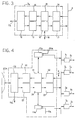
- the unit 5 whose structure is shown in detail in Figure 4, comprises instead, in the direction from the bus structure to the ATM network:
- the circuit 22, in one direction, and the circuit 23, in the opposite direction, are connected to an interface circuit 26 comprising essentially a PDH interface towards the ATM network: in practice, it is a physical interface which is also able to provide block 6 with alarms (line 50c) related to the quality of the connection set up through the device 1.
- Bus structure 4 operates so that, at the receiving side (with reference to modules 3 k ), it interconnects all the transmission sections (circuit 14) of the modules 3 k to the reception section (circuit 25) of the central unit 5. This takes place by implementing a structure which can essentially be seen as a tripartite structure.
- a first section of the bus 4 transports data from the unit 5 towards the modules 3 k : in practice, the cells extracted in the unit 5 from the frame received from the ATM network are made available on the bus 4.
- a second section of the bus enables reception in a certain module 3 k , by making available on the bus 4 the identifier of the module 3 k (provided by the table of connections contained in 24a) towards which the content of the data section is to be addressed.
- a third section of the bus contains information about the synchronisation and the timing of the different components making up the reception section, i.e.:
- bus 4 is organised according to a tripartite structure.
- a first section of the bus conveys the cells assembled (circuit 12 in Figure 3) in the various modules 3 k .
- a second section of the bus assigns a request line to each module 3 k ; the transmission of one or more requests on this section of the bus entails the enabling, accomplished by the centralised unit 5 by assigning the corresponding address on the respective wires of the bus, of the module having to access the data section of the bus in order to insert thereon the related outgoing cells.
- a third section of the bus conveys, also during transmission, all cell synchronisation and system timing information.
- the signals present are those corresponding to:
- the access phases of the modules 3 k to the bus 4 are coordinated so as to avoid conflict situations and to guarantee the same opportunity for accessing bus 4 to all modules 3 k .
- the centralised unit 5 is dimensioned in such a way as to be able to multiplex cells corresponding to a data flow (at least) equal to the sum of the flows of the lines 2 k , into a single flow of ATM cells.
- the flow chart in Figure 5 shows, by way of example, the possible criteria for managing the aforesaid mechanism for access to bus 4 accomplished by the element 21a under the control of the unit 6.
- a check is performed on the occupation state of the transmission bus by one of the modules 3 1 ...3 k ...3 n .
- step 101 by analysing the logic sum (OR) of all transmission requests, the presence of at least one active request is detected. Two cases can occur.
- step 104 the request with the highest current priority is identified (in particular; the request coming from the module whose last access to the bus 4 is the farthest in time).
- the coding corresponding to the request line served (the one with the highest priority) is sent on the bus enabling the transmission sections of the modules 3 1 ...3 k ...3 n .
- the priority of the request just served is cancelled this can be obtained, in a wholly conventional manner; by queuing the identity of the module just served to a list of modules which have requested access, so that the first module of the list is the one whose request has the highest priority.
- a first family which can be defined as meta-signalling protocols, comprises the protocols related to the phase in which the network assigns a signalling channel dedicated to the dialogue between a specific device 1 and the ATM network.
- the second family which can be defined as signalling protocols, comprises the protocols related to the management of the connections among the various terminals present in the network and to the control of the functionalities of the apparatuses.
- the ATM management centre assigns it a dedicated signaling virtual channel.
- the identification of this channel takes place by introducing into the header of the cells forming the channel itself a particular identifier called SVCI (Signalling Virtual Channel Identifier) in accordance with the ITU I.361 specifications.
- SVCI Simalling Virtual Channel Identifier
- This assignment occurs on demand by the device 1 which, upon becoming connected in the network, transmits a request on a virtual channel (denominated MSVC: Meta-signalling Virtual Channel) dedicated to this purpose and shared by all terminals connected in the network.
- a virtual channel denoted MSVC: Meta-signalling Virtual Channel
- meta-signalling protocols The purpose of the meta-signalling protocols is to collect all requests by the applications desiring to dialogue with the network and to assign each of them an appropriate Signalling Virtual Channel SVC. The same protocols must be able to release these assignments once an application is disconnected from the network.
- the device 1 After assignment by the ATM network of the signalling virtual channel, the device 1 is able to perform all operations related to management of the connections, listed below:
- Figure 6b shows the procedure for setting up a connection between two applications, each connected to a respective device 1. Routing in the device 1 of the data flows from the ATM network interface towards the respective application outputs and vice versa is co-ordinated by the device 1/device 1 protocol to be described farther on.
Abstract
Description
- general modularity and configuration capability, in particular in regard to the interfaces on the application side, i.e. those facing the connection oriented lines;
- adaptability of the centralised part to the different interfaces;
- flexibility in the allocation of ATM resources with respect to the activation/deactivation of services on the application side, for instance by allowing the bit rate to be programmed at 64 kbit/s steps and/or by assigning each module (application) only the useful bandwidth structured in ATM cells; and
- general capability of constructing removable and replaceable interfaces.
- Figure 1 shows the typical scenario of use of a device according to the invention,
- Figure 2 shows, as a general block diagram, the overall architecture of the device according to the invention,
- Figures 3 and 4 are two additional functional block diagrams showing the structure of two parts comprised in a device according to the invention,
- Figure 5 shows, in the form of a flow chart, the criteria for managing transmission requests in a device according to the invention, and
- Figure 6, organised in three parts, indicated respectively as 6a, 6b and 6c, shows the criteria for performing the signalling function in a device according to the invention.
- a
segmentation circuit 11 which, after a series/parallel conversion, subdivides the incoming data flow received from the line 2k (through the circuit 10) into a sequence of packets destined to constitute the payload of the ATM cell; this operation takes place according to a general operating principle governed by a FIFO (First In - First Out) logic; - an assembling
circuit 12 which assembles the packets received from thesegmentation circuit 11 with the header data received from the control unit 6 in order to construct the ATM cells, including the related control signals destined to be used by the unit 6 to identify each cell, and - an
additional interface circuit 13 which sends the ATM cells constructed by thecircuit 12 over the bus 4 for their transfer towards theunit 5.
- an
interface circuit 14 which receives from the bus 4 the ATM cells coming from theunit 5, - a
circuit 15 for frame integrity verification, which analyses the flow of cells received from theinterface 14 and verifies that no cells have been lost by the ATM network (and, if need be, integrates the flow of cells with "stuffing" cells to preserve frame integrity), and - an
extraction circuit 16 which, substantially, definitively breaks up the ATM cells and reconstructs the original structure of the data flow destined to be sent towards theline 2k through the interface 10.
- an
interface circuit 20 destined essentially to allow interworking of theunit 5 with the various modules 3k, through the bus 4, - a
multiplexing circuit 21 which multiplexes the different data flows coming from the different modules 3k, connected to the bus 4, into a single flow of ATM cells;multiplexing circuit 21 is associated with anelement 21a whose function is to manage the transmission resources, under the control of unit 6 (line 50a being part of theconnection 50, together withlines 50b, 50c which shall be seen farther on). - a
mapping circuit 22 which maps the aforesaid cells in the PDH (Plesiochronous Digital Hierarchy) frame used for transport by the ATM network: in practice, thecircuit 22 inserts cells coming from themultiplexing circuit 21 into the frame, by inserting empty cells (so-called "idle" cells) into the band-width portion not used for transport and by managing the fields of the frame destined to service information (overhead).
- an extracting
circuit 23 which extracts the cells from the PDH frame of the ATM network, in particular by identifying and extracting the cells pertaining to the activated connections, - a routing circuit 24 (in practice a demultiplexer) which routes each cell
received towards a respective module 3k, by comparing the cell header with
a routing table of the connections stored in a
circuit 24a acting under the control of the control unit 6 (line 50b), and - an
interface 25 whose function is essentially analogous to that of theinterface circuit 20, except for the different direction of operation.
- the byte clock of the data flow,
- a template identifying the payload of the ATM cell (typically from byte 6 to byte 53), and
- the cell synchronism in correspondence with the first byte of the payload.
- the byte clock of the data flow;
- the cell synchronism, usually present half a period before the start of the cell, and
- an enabling window for the search for transmission requests, activated for example in correspondence with the fiftieth byte of the cell and deactivated as soon as an active request is detected.
- all modules 3k can access, in a virtually simultaneous manner; the ATM network, in practice as separate connections and without limitations imposed on the incoming and/or outgoing flows, and
- an automatic adaptation of the requests imposed to the ATM network according to instantaneous transport needs is obtained: thus the allocation of a fixed transport capacity, which would be exposed to the risk of a greatly incomplete usage, is avoided.
- the first one is due to the absence of transmission requests by all modules 31...3k...3n of the apparatus;
- the second one due to the fact that during the servicing processes of the active requests, all the priorities of the requests were cancelled.
- set up and release of a connection: the device must be able to manage independently a number of connections equal to the number of application inputs it is fitted with; in particular the device must be able to add or remove connections without affecting the operations of the active ones;
- dialogue with the network: it defines the characteristics of the service assigned to each application interface requiring a new connection;
- monitoring and control over any malfunctions in the interface apparatuses to and from the network.
Claims (14)
- Device for interfacing an ATM network and a plurality of connection oriented lines (21...2k...2n), characterised in that it comprises:a plurality of modules (31...3k...3n) allowing direct access to the ATM network by at least one respective connection oriented line (21...2k...2n) and arranged to accomplish, starting from a flow of digital data received on said connection oriented line, a segmentation of said data into ATM cells and, conversely, to reconstruct an outgoing data flow on at least one respective line (21...2k...2n) starting from ATM cells, anda centralised unit (5) which is connected to the modules of said plurality (31...3k...3n), is tasked with manipulating ATM flows and managing access requests by said connection oriented lines (21...2k...2n), and is arranged to multiplex ATM cells received from said modules (31...3k...3n) into a flow of cells which can be managed by said ATM network and, respectively, of demultiplexing a flow of cells managed by said ATM network into ATM cells each routed towards a respective module (31...3k...3n) of said plurality, said centralised unit (5) dynamically assigning the access band available on the ATM network according to the access requests by said modules (31...3k...3n), by handling individual requests as separate connections.
- Device as claimed in claim 1, characterised in that the modules of said plurality (31...3k...3n) are connected to said centralised unit (5) through a bus structure (4).
- Device as claimed in claim 2, characterised in that the access by the modules of said plurality (31...3k...3n) to said bus structure (4) is governed with a priority mechanism that assigns the lowest priority to the module which has just obtained access to the bus structure (4) and the highest priority to the module whose last access to the bus structure (4) is the farthest in time.
- Device as claimed in any of the previous claims, characterised in that said centralised unit (5) is so dimensioned as to be capable of multiplexing ATM cells corresponding to a data flow equal to the sum of the flows of said connection lines (21...2k...2n) into a single flow of ATM cells directed towards said ATM network.
- Device as claimed in any of the previous claims, characterised in that said modules (31...3k...3n) comprise, in the path from said connection lines (21...2k...2n) towards said centralised unit (5), a circuit (11) for the segmentation of the respective data flow and a circuit (12) for the construction of a respective ATM cell starting from each segment formed by said segmentation circuit (11).
- Device as claimed in any of the previous claims, characterised in that said modules (31...3k...3n) comprise, in the path from said centralised unit (5) towards said connection lines (21...2k...2n) a circuit (15) for verifying the integrity of a frame into which ATM cell flows are organised and a circuit (16) for the selective extraction from said frame of the data flow destined to the respective connection line (21...2k...2n).
- Device as claimed in claim 6, characterised in that said circuit (15) for frame integrity verification is arranged so as to insert into said frame stuffing cells in the bandwidth portion not used for transporting the related flow.
- Device as claimed in any of the previous claims, characterised in that said centralised unit (5) comprises, in the path from said modules (31...3k...3n) towards said ATM network, a circuit (21) for multiplexing the ATM cells received from respective modules, associated with a circuit (21a) for managing the transmission resources, and a circuit (22) for mapping said multiple xed cells into a frame of ATM cells.
- Device as claimed in any of the previous claims, characterised in that said centralised unit (5) comprises, in the path from said ATM network towards said modules (31...3k...3n) a circuit (23) for cell extraction from an ATM frame and a circuit (24, 24a) for the selective routing of the extracted cells towards respective modules of said plurality (31...3k...3n).
- Device as claimed in any of the previous claims, characterised in that said modules (31...3k...3n) comprise, on the side connected to said connection lines (21...2k...2n) a physical interface (10) towards said connection lines.
- Device as claimed in any of the previous claims, characterised in that it comprises a control unit (6) for the control of the operation of said centralised unit (5) and of said modules (31...3k...3n).
- Device as claimed in claim 11, characterised in that said control unit (6) can be configured in at least a master configuration, where the respective device (1) is capable of controlling at least another analogous device connected to said ATM network, and at least a slave configuration, where the respective device (1) is capable of being controlled by at least another analogous device connected to said ATM network.
- Device as claimed in any of the previous claims, characterised in that at least some of said modules (31...3k...3n) are selectively removable in view of their replacement with other modules.
- Device as claimed in any of the previous claims, characterised in that it comprises means (6) for generating a request for allocating a first signalling virtual channel (MSCV) on the ATM network, which channel is shared with at least another homologous device (1) connected to the ATM network itself, in view of the allocation, to the device generating said request, of a respective second signalling virtual channel (SVC) on the ATM network.
Applications Claiming Priority (2)
| Application Number | Priority Date | Filing Date | Title |
|---|---|---|---|
| ITTO961096 | 1996-12-30 | ||
| IT96TO001096A IT1289816B1 (en) | 1996-12-30 | 1996-12-30 | INTERFACE DEVICE FOR ATM TYPE NETWORKS |
Publications (3)
| Publication Number | Publication Date |
|---|---|
| EP0855845A2 true EP0855845A2 (en) | 1998-07-29 |
| EP0855845A3 EP0855845A3 (en) | 1998-08-12 |
| EP0855845B1 EP0855845B1 (en) | 2002-09-04 |
Family
ID=11415168
Family Applications (1)
| Application Number | Title | Priority Date | Filing Date |
|---|---|---|---|
| EP97122923A Expired - Lifetime EP0855845B1 (en) | 1996-12-30 | 1997-12-28 | Interfacing device for ATM networks |
Country Status (7)
| Country | Link |
|---|---|
| US (1) | US6115381A (en) |
| EP (1) | EP0855845B1 (en) |
| JP (1) | JP2979504B2 (en) |
| CA (1) | CA2225869C (en) |
| DE (2) | DE855845T1 (en) |
| ES (1) | ES2123481T3 (en) |
| IT (1) | IT1289816B1 (en) |
Families Citing this family (6)
| Publication number | Priority date | Publication date | Assignee | Title |
|---|---|---|---|---|
| KR100251779B1 (en) * | 1997-07-25 | 2000-04-15 | 윤종용 | An interfacing apparatus between pdh network and atm network |
| US6667955B1 (en) * | 1998-08-28 | 2003-12-23 | International Business Machines Corporation | Switching fabric system having at least one subsystem including switch core elements arranged in port expansion architecture |
| IL130039A (en) * | 1999-05-19 | 2003-07-06 | Eci Telecom Ltd | Cell bus and method for using same |
| US6574232B1 (en) * | 1999-05-26 | 2003-06-03 | 3Com Corporation | Crossbar switch utilizing broadcast buffer and associated broadcast buffer management unit |
| KR100318404B1 (en) | 2000-02-22 | 2001-12-22 | 박종섭 | BTS interface subsystem in IMT-2000 base station controller |
| US8442077B2 (en) * | 2005-02-28 | 2013-05-14 | Jds Uniphase Corporation | Automatically configuring a distributed network analyzer to monitor identified inverse multiplex groups of an asynchronous transfer mode network |
Citations (2)
| Publication number | Priority date | Publication date | Assignee | Title |
|---|---|---|---|---|
| EP0512495A2 (en) * | 1991-05-07 | 1992-11-11 | Fujitsu Limited | Switching node in a network with label multiplexed information |
| EP0581087A1 (en) * | 1992-07-31 | 1994-02-02 | Siemens Aktiengesellschaft | Method for representing subscriber's individual data when transmitting signalling signals and information signals between narrow band networks and ATM-networks |
Family Cites Families (11)
| Publication number | Priority date | Publication date | Assignee | Title |
|---|---|---|---|---|
| JP2521368B2 (en) * | 1990-08-21 | 1996-08-07 | 三菱電機株式会社 | Packet adapter device for ATM |
| JPH0537545A (en) * | 1991-07-16 | 1993-02-12 | Fujitsu Ltd | Alarm transfer system and atm communication equipment using the system |
| JPH05160850A (en) * | 1991-12-10 | 1993-06-25 | Nec Commun Syst Ltd | Wide band isdn terminal adaptor |
| US5524113A (en) * | 1993-08-30 | 1996-06-04 | Washington University | ATM switch interface |
| US5852606A (en) * | 1995-07-12 | 1998-12-22 | Bay Networks, Inc. | Method and apparatus for transmitting cells across an ATM switch bus |
| US5996019A (en) * | 1995-07-19 | 1999-11-30 | Fujitsu Network Communications, Inc. | Network link access scheduling using a plurality of prioritized lists containing queue identifiers |
| US5844887A (en) * | 1995-11-30 | 1998-12-01 | Scorpio Communications Ltd. | ATM switching fabric |
| US5742765A (en) * | 1996-06-19 | 1998-04-21 | Pmc-Sierra, Inc. | Combination local ATM segmentation and reassembly and physical layer device |
| JP3819438B2 (en) * | 1996-08-16 | 2006-09-06 | ノーテル・ネットワークス・リミテッド | Demultiplexing digital data |
| US5959996A (en) * | 1996-09-05 | 1999-09-28 | Lucent Technologies | System for interfacing numerous ISDN data connecting to a data network through the telephone network |
| US5953338A (en) * | 1996-12-13 | 1999-09-14 | Northern Telecom Limited | Dynamic control processes and systems for asynchronous transfer mode networks |
-
1996
- 1996-12-30 IT IT96TO001096A patent/IT1289816B1/en active IP Right Grant
-
1997
- 1997-11-24 US US08/977,099 patent/US6115381A/en not_active Expired - Lifetime
- 1997-12-25 JP JP36613597A patent/JP2979504B2/en not_active Expired - Lifetime
- 1997-12-28 ES ES97122923T patent/ES2123481T3/en not_active Expired - Lifetime
- 1997-12-28 EP EP97122923A patent/EP0855845B1/en not_active Expired - Lifetime
- 1997-12-28 DE DE0855845T patent/DE855845T1/en active Pending
- 1997-12-28 DE DE69715143T patent/DE69715143T2/en not_active Expired - Lifetime
- 1997-12-29 CA CA002225869A patent/CA2225869C/en not_active Expired - Lifetime
Patent Citations (2)
| Publication number | Priority date | Publication date | Assignee | Title |
|---|---|---|---|---|
| EP0512495A2 (en) * | 1991-05-07 | 1992-11-11 | Fujitsu Limited | Switching node in a network with label multiplexed information |
| EP0581087A1 (en) * | 1992-07-31 | 1994-02-02 | Siemens Aktiengesellschaft | Method for representing subscriber's individual data when transmitting signalling signals and information signals between narrow band networks and ATM-networks |
Also Published As
| Publication number | Publication date |
|---|---|
| ES2123481T1 (en) | 1999-01-16 |
| DE69715143T2 (en) | 2003-04-17 |
| EP0855845B1 (en) | 2002-09-04 |
| EP0855845A3 (en) | 1998-08-12 |
| CA2225869C (en) | 2002-07-23 |
| US6115381A (en) | 2000-09-05 |
| DE855845T1 (en) | 1999-01-07 |
| ITTO961096A1 (en) | 1998-06-30 |
| JPH10210055A (en) | 1998-08-07 |
| IT1289816B1 (en) | 1998-10-16 |
| CA2225869A1 (en) | 1998-06-30 |
| ES2123481T3 (en) | 2003-03-16 |
| DE69715143D1 (en) | 2002-10-10 |
| JP2979504B2 (en) | 1999-11-15 |
Similar Documents
| Publication | Publication Date | Title |
|---|---|---|
| US5247516A (en) | Configurable composite data frame | |
| JP3786373B2 (en) | ATM network interface device | |
| EP0596624B1 (en) | Bandwidth allocation, transmission scheduling, and congestion avoidance in broadband asynchronous transfer mode networks | |
| US5282207A (en) | Frame compression in integrated services networks | |
| USRE41970E1 (en) | Method for the control of flows within an ATM switch with distributed architecture | |
| EP1078550B1 (en) | ADAPTIVE SCHEDULING METHOD AND APPARATUS TO SERVICE MULTILEVEL QoS IN AAL2 | |
| US5251209A (en) | Prioritizing attributes in integrated services networks | |
| US4965790A (en) | Communication system for forming different networks on the same ring transmission line | |
| US5946323A (en) | Asynchronous transfer mode integrated access service | |
| US6272128B1 (en) | Method and system for emulating a T1 link over an ATM network | |
| JP2002111741A (en) | Method and system for transferring information in optical communication network | |
| EP0855845B1 (en) | Interfacing device for ATM networks | |
| EP0797373B1 (en) | A method and apparatus for converting synchronous narrowband signals into broadband asynchronous transfer mode signals in an integrated telecommunications network | |
| JPH10322376A (en) | Local area network with converter means | |
| WO1998015066A2 (en) | Private branch exchange, telecommunication system and methods of transmitting signals in subrate channels | |
| AU721715B2 (en) | Arrangement for interleaving data and signalling information | |
| JPH08214002A (en) | Connectionless communication system, its test method and intra-station control system | |
| US20050068986A1 (en) | Universal switching centre, method for executing a switching task, input unit, output unit and connecting unit | |
| US7120506B1 (en) | Method, system, converter and switch for asynchronous transmission-mode (ATM) communication | |
| Green et al. | Prospects and design choices for integrated private networks | |
| JPH11331267A (en) | Subscriber line transmitter | |
| JPH05252176A (en) | Input/output information control system for digital switching | |
| Muth | Logical Network Modelling | |
| Goeldner et al. | Architecture of a New Inhouse Communication System Providing Integrated Circuit and Packet Switching | |
| Ahmad | Multiplexing and Carrier Systems |
Legal Events
| Date | Code | Title | Description |
|---|---|---|---|
| PUAI | Public reference made under article 153(3) epc to a published international application that has entered the european phase |
Free format text: ORIGINAL CODE: 0009012 |
|
| PUAL | Search report despatched |
Free format text: ORIGINAL CODE: 0009013 |
|
| AK | Designated contracting states |
Kind code of ref document: A2 Designated state(s): DE ES FR GB GR IT NL SE |
|
| AX | Request for extension of the european patent |
Free format text: AL;LT;LV;MK;RO;SI |
|
| AK | Designated contracting states |
Kind code of ref document: A3 Designated state(s): AT BE CH DE DK ES FI FR GB GR IE IT LI LU MC NL PT SE |
|
| AX | Request for extension of the european patent |
Free format text: AL;LT;LV;MK;RO;SI |
|
| 17P | Request for examination filed |
Effective date: 19980817 |
|
| EL | Fr: translation of claims filed | ||
| TCNL | Nl: translation of patent claims filed | ||
| DET | De: translation of patent claims | ||
| REG | Reference to a national code |
Ref country code: ES Ref legal event code: BA2A Ref document number: 2123481 Country of ref document: ES Kind code of ref document: T1 |
|
| AKX | Designation fees paid |
Free format text: DE ES FR GB GR IT NL SE |
|
| RBV | Designated contracting states (corrected) |
Designated state(s): DE ES FR GB GR IT NL SE |
|
| GRAG | Despatch of communication of intention to grant |
Free format text: ORIGINAL CODE: EPIDOS AGRA |
|
| 17Q | First examination report despatched |
Effective date: 20011211 |
|
| GRAG | Despatch of communication of intention to grant |
Free format text: ORIGINAL CODE: EPIDOS AGRA |
|
| GRAH | Despatch of communication of intention to grant a patent |
Free format text: ORIGINAL CODE: EPIDOS IGRA |
|
| RAP1 | Party data changed (applicant data changed or rights of an application transferred) |
Owner name: TELECOM ITALIA LAB S.P.A. |
|
| GRAH | Despatch of communication of intention to grant a patent |
Free format text: ORIGINAL CODE: EPIDOS IGRA |
|
| GRAA | (expected) grant |
Free format text: ORIGINAL CODE: 0009210 |
|
| AK | Designated contracting states |
Kind code of ref document: B1 Designated state(s): DE ES FR GB GR IT NL SE |
|
| PG25 | Lapsed in a contracting state [announced via postgrant information from national office to epo] |
Ref country code: GR Free format text: LAPSE BECAUSE OF FAILURE TO SUBMIT A TRANSLATION OF THE DESCRIPTION OR TO PAY THE FEE WITHIN THE PRESCRIBED TIME-LIMIT Effective date: 20020904 |
|
| REG | Reference to a national code |
Ref country code: GB Ref legal event code: FG4D |
|
| REF | Corresponds to: |
Ref document number: 69715143 Country of ref document: DE Date of ref document: 20021010 |
|
| ET | Fr: translation filed | ||
| REG | Reference to a national code |
Ref country code: ES Ref legal event code: FG2A Ref document number: 2123481 Country of ref document: ES Kind code of ref document: T3 |
|
| PLBE | No opposition filed within time limit |
Free format text: ORIGINAL CODE: 0009261 |
|
| STAA | Information on the status of an ep patent application or granted ep patent |
Free format text: STATUS: NO OPPOSITION FILED WITHIN TIME LIMIT |
|
| 26N | No opposition filed |
Effective date: 20030605 |
|
| PG25 | Lapsed in a contracting state [announced via postgrant information from national office to epo] |
Ref country code: IT Free format text: LAPSE BECAUSE OF NON-PAYMENT OF DUE FEES Effective date: 20071228 |
|
| REG | Reference to a national code |
Ref country code: FR Ref legal event code: PLFP Year of fee payment: 19 |
|
| REG | Reference to a national code |
Ref country code: FR Ref legal event code: PLFP Year of fee payment: 20 |
|
| PGFP | Annual fee paid to national office [announced via postgrant information from national office to epo] |
Ref country code: GB Payment date: 20161228 Year of fee payment: 20 Ref country code: NL Payment date: 20161226 Year of fee payment: 20 |
|
| PGFP | Annual fee paid to national office [announced via postgrant information from national office to epo] |
Ref country code: ES Payment date: 20161227 Year of fee payment: 20 Ref country code: SE Payment date: 20161129 Year of fee payment: 20 Ref country code: FR Payment date: 20161227 Year of fee payment: 20 |
|
| PGFP | Annual fee paid to national office [announced via postgrant information from national office to epo] |
Ref country code: DE Payment date: 20161229 Year of fee payment: 20 |
|
| PGFP | Annual fee paid to national office [announced via postgrant information from national office to epo] |
Ref country code: IT Payment date: 20161222 Year of fee payment: 20 |
|
| REG | Reference to a national code |
Ref country code: DE Ref legal event code: R071 Ref document number: 69715143 Country of ref document: DE |
|
| REG | Reference to a national code |
Ref country code: NL Ref legal event code: MK Effective date: 20171227 |
|
| REG | Reference to a national code |
Ref country code: GB Ref legal event code: PE20 Expiry date: 20171227 |
|
| REG | Reference to a national code |
Ref country code: SE Ref legal event code: EUG |
|
| PG25 | Lapsed in a contracting state [announced via postgrant information from national office to epo] |
Ref country code: GB Free format text: LAPSE BECAUSE OF EXPIRATION OF PROTECTION Effective date: 20171227 |
|
| REG | Reference to a national code |
Ref country code: ES Ref legal event code: FD2A Effective date: 20180508 |
|
| PG25 | Lapsed in a contracting state [announced via postgrant information from national office to epo] |
Ref country code: ES Free format text: LAPSE BECAUSE OF EXPIRATION OF PROTECTION Effective date: 20171229 |