EP0856871A1 - Fluorescent lamp - Google Patents
Fluorescent lamp Download PDFInfo
- Publication number
- EP0856871A1 EP0856871A1 EP97101366A EP97101366A EP0856871A1 EP 0856871 A1 EP0856871 A1 EP 0856871A1 EP 97101366 A EP97101366 A EP 97101366A EP 97101366 A EP97101366 A EP 97101366A EP 0856871 A1 EP0856871 A1 EP 0856871A1
- Authority
- EP
- European Patent Office
- Prior art keywords
- phosphor
- fluorescent lamp
- phosphor coating
- lamp according
- glass bulb
- Prior art date
- Legal status (The legal status is an assumption and is not a legal conclusion. Google has not performed a legal analysis and makes no representation as to the accuracy of the status listed.)
- Withdrawn
Links
Images


Classifications
-
- H—ELECTRICITY
- H01—ELECTRIC ELEMENTS
- H01J—ELECTRIC DISCHARGE TUBES OR DISCHARGE LAMPS
- H01J61/00—Gas-discharge or vapour-discharge lamps
- H01J61/02—Details
- H01J61/38—Devices for influencing the colour or wavelength of the light
- H01J61/42—Devices for influencing the colour or wavelength of the light by transforming the wavelength of the light by luminescence
- H01J61/48—Separate coatings of different luminous materials
-
- H—ELECTRICITY
- H01—ELECTRIC ELEMENTS
- H01J—ELECTRIC DISCHARGE TUBES OR DISCHARGE LAMPS
- H01J61/00—Gas-discharge or vapour-discharge lamps
- H01J61/02—Details
- H01J61/38—Devices for influencing the colour or wavelength of the light
- H01J61/42—Devices for influencing the colour or wavelength of the light by transforming the wavelength of the light by luminescence
- H01J61/44—Devices characterised by the luminescent material
Definitions
- This invention relates to a fluorescent lamp, and particularly to the improvement of a fluorescent lamp that emits an afterglow sufficient to allow discernment of objects for at least ten minutes after the lamp is extinguished.
- Fluorescent lamps for illumination purposes are generally constructed by forming a phosphor coating composed of, for example, a halophosphate phosphor or rare-earth phosphor on the inner surface of a glass bulb.
- a straight-tube 40-watt fluorescent lamp using a halophosphate phosphor produces a luminous intensity of 2700-3100 (lm) and is widely used for such purposes as lighting offices, large stores, theaters, baths, and underground shopping malls.
- the Fire Law and Building Standards Law stipulate the provision of guide lights or emergency lighting.
- Such guide lights or emergency lighting are constructed to allow use of a commercial power source during normal operation, but during emergencies (blackouts), to allow use of an internal battery to light a fluorescent lamp or light bulb at an illuminance of 1 lx or greater for at least 20-30 minutes. During emergencies, therefore, a minimum illuminance at the ground surface of 1 lx or greater can be ensured to enable safe and speedy evacuation even when the commercial power source is interrupted and normal lighting apparatus are nonfunctional.
- guide lights or emergency lighting are costly and, compared to normal lighting fixtures, few in number.
- passageway guide lights are arranged along lower wall surfaces, people far from the wall will be a considerably less aware of the passageway guide lamps than people close to the wall during the confusion of an evacuation, and this reduced awareness may hinder the speed of evacuation.
- smooth and speedy evacuation may be hindered by the lack of light during a blackouts caused by a disaster, and evacuation of children or disabled persons may be hindered.
- the present applicants therefore proposed a fluorescent lamp having a phosphor coating composed of one or more varieties of phosphors on the inner surface of a glass bulb, this phosphor coating being a mixture including at least 0.2 mg per 1 cm 2 of a phosphor having a long afterglow property.
- an illuminance of at least 0.05 lx which allows discernment of objects, can be obtained even after the passage of 500 seconds after the fluorescent lamp has been extinguished, and the fluorescent lamp therefore provides the functions of both a guide light in a blackout as well as an ordinary night-light.
- this fluorescent lamp produces a brightness of only 40% that of ordinary fluorescent lamps for lighting purposes, and this leads to the problem that the number of lamps installed for ordinary use must be increased to attain the desired illuminance at floor level, thereby increasing the financial burden of using such lamps.
- the object of the present invention is to provide a fluorescent lamp that allows an improvement in the degree to which light can be put to practical use through a comparatively simple construction and with no loss in extended afterglow property.
- the present invention is a fluorescent lamp formed by layering first and second phosphor coatings composed of one or more types of phosphors on the inner surface of a glass bulb, wherein the first phosphor coating on the glass bulb side is formed from a phosphor having a long afterglow property.
- the application amount of phosphor having a long afterglow property of the first phosphor coating is set to at least 0.2 mg per 1 cm 2
- the second phosphor coating is formed from a phosphor having a long afterglow property
- the second phosphor coating is formed from one or more rare-earth phosphors.
- an ultraviolet light reflection layer is formed between the glass bulb and first phosphor coating, and this ultraviolet light reflection layer is constituted from alumina or magnesia.
- a transparent conductive film is formed between the glass bulb and the first phosphor coating, and in addition, an ultraviolet light reflection layer is formed between this conductive film and the first phosphor coating.
- the outer surface of the glass bulb is covered by a transparent protective layer, and in addition, this protective layer is constituted from a resin tube.
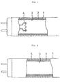
- Fig. 1 is a sectional view showing the principal components of the first embodiment of a fluorescent lamp according to the present invention.
- Fig. 2 is a sectional view showing the principal components of the second embodiment of the present invention.
- Fig 3 is a sectional view showing the principal components of the third embodiment of the present invention.
- Fig. 4 is a sectional view showing the principal components of the fourth embodiment of the present invention.
- Fig. 5 is a graph showing the relation of the afterglow illuminance to the time elapsed after extinguishing for an embodiment of the present invention.
- Fig. 6 is an enlarged view of the illuminance scale of Fig. 5.
- a first phosphor coating 2 composed of at least one type of phosphor having a long afterglow property is formed on the inner surface of glass bulb 1. This first phosphor coating 2 is formed at an application amount of at least 0.2 mg per 1 cm 2 .
- a chemical compound that can be represented by, for example, the general formula MAl 2 O 4 , wherein M is a light-accumulating phosphor in which a chemical compound composed of at least one metal element selected from the group composed of calcium, strontium, and barium is made the mother crystal, and in addition to the use of europium (Eu) as an activator, an element such as dysprosium (Dy) or neodymium (Nd) is used as a co-activator.
- Eu europium
- Dy dysprosium
- Nd neodymium
- the average particle diameter of these phosphors is set to, for example, 2-12 ⁇ m (according to the Fischer Subsieve Sizer Method(FSSS)).
- Second phosphor coating 3 composed of one or more phosphors is layered over first phosphor coating 2.
- An application amount within the range of 2-5 mg per 1 cm 2 is effective for this second phosphor coating 3, with 3.3 mg being the optimum application amount, and the layer is formed by mixing one or more types of, for example, halophosphate phosphors (Ca 10 (PO 4 ) 6 FCl : Sb/Mn, etc.) or rare-earth phosphors (Y 2 O 3 : Eu, LaPO 4 : Ce/Tb, (SrCaBaMg) 5 (PO 4 ) 3 Cl : Eu, etc.).
- the layer thickness can be made relatively uniform by setting the application direction at the time of forming second phosphor coating 3 opposite to the application direction at the time of forming first phosphor coating 2.
- electrodes 4 are arranged at both ends of glass bulb 1.
- At least second phosphor coating 3 on the discharge path side is constituted from a phosphor such as a rare-earth phosphor used in ordinary fluorescent lamps for lighting purposes, and consequently, when the lamp is turned on, this phosphor is efficiently excited by ultraviolet light of, for example, 253.7 nm wavelength, and a significant increase in brightness can therefore be realized.
- first phosphor coating 2, being formed on the glass bulb side is excited by ultraviolet light passing through second phosphor coating 3 and also emits light.
- second phosphor coating 3 is excited by ultraviolet light passing through second phosphor coating 3 and also emits light.
- first phosphor coating 2 can maintain an illuminance on the order of 0.05 lx, which allows discernment of objects, over a long time interval after the fluorescent lamp is extinguished.
- the use of the fluorescent lamp of the present invention obviates the use of the miniature bulbs on the order of 5 W which are often mounted in household lighting fixtures for use as night-lights, thereby allowing both a reduction in the cost for light fixtures as well as a reduction in electrical power use.
- Fig. 2 shows another embodiment of the present invention in which a transparent ultraviolet light reflection layer 5 is formed between glass bulb 1 and first phosphor coating 2.
- This ultraviolet light reflection layer 5 is formed from, for example, alumina (Al 2 O 3 ) or magnesia (MgO) having an average particle diameter of less than, for example, 0.1 ⁇ m, and preferably between 30 and 50 nm.
- First and second phosphor coatings 2 and 3 are excited by ultraviolet light of, for example, 253.7 nm wavelength produced by discharge between electrodes 4, but while the phosphor located on the discharge path side is efficiently excited, the phosphor located on the glass bulb side and farther from the discharge path tends to be excited at a reduced level of efficiency.
- ultraviolet light that passes through first and second phosphor coatings 2 and 3 is reflected by ultraviolet light reflection layer 5, and phosphor located on the glass bulb side is therefore excited both by ultraviolet light passing through and by ultraviolet light that is reflected back.
- the luminous efficacy of this lamp can consequently be increased.
- ultraviolet light reflection layer 5 from, for example, alumina allows suppression of contact by mercury with glass bulb 1, thereby reducing or eliminating changes in color due to solarization.
- Fig. 3 shows a different embodiment of the present invention in which a transparent conductive film 6 is formed between glass bulb 1 and first phosphor coating 2.
- This conductive film 6 is formed by, for example, spray application of a liquid containing tin chloride onto the inner surface of glass bulb in a heated state.
- This film 6 has a resistance of, for example, 1-1000 k ⁇ level.
- This embodiment can be applied to lighting fixtures equipped with a ignition circuit device for rapid-start lighting, and is ideal for use in locations such large stores, theaters, and underground shopping malls where a reduction in time for maintenance is desirable.
- FIG. 4 shows yet another embodiment of the present invention in which a protective layer 7 is formed on the outer surface of glass bulb 1.
- This protective layer 7 is composed of, for example, a resin material such as a polyethylene terephtalate (PET) having a thickness set to, for example, 100-150 ⁇ m.
- PET polyethylene terephtalate
- This protective layer 7 is formed by first preparing a tube form, and after inserting glass bulb 1, heating to 150-200°C to cause the tube to shrink and come into close contact with the outer surface of glass bulb 1.
- an ultraviolet light absorbent such as titanium oxide (TiO 2 ) is mixed into protective layer 7, not only can the light resistance of protective layer 7 be improved, but the protective layer 7 can also serve as an ultraviolet light blocking layer.
- This construction may also be applied to the fluorescent lamps shown in Figs. 2 and 3.
- a protective layer 7 made of resin is formed on the outer surface of glass bulb 1, and this protective layer 7 not only prevents glass bulb 1 from shattering should breakage occur in an emergency, but also allows emission of enough light when the bulb is broken to enable discernment of objects, thereby enabling smooth and speedy evacuation.
- this fluorescent lamp may be removed from a light fixture and used as a substitute for a flashlight, an example which illustrates that the present invention can be of service in countless ways beyond serving as a guide light for evacuation.
- the present invention is not restricted to any of the above-described embodiments, and may of course be applied to straight-tube fluorescent lamps other than a 40-watt model, as well as to circular fluorescent lamps, compact fluorescent lamps, and globe fluorescent lamps.
- a phosphor having a long afterglow property any substance having long afterglow properties may be used in addition to those described in the embodiments hereinabove such as a europium-, neodymium-, and yttrium-activated calcium aluminate phosphor (CaAl 2 O 4 : Eu/Nd/Y).
- triphosphor fluorescent lamps of the three or more types of phosphors within the second phosphor coating, at least one type can be exchanged for a phosphor having long afterglow properties.
- the inventors of the present invention first fabricated an FL40 fluorescent lamp using a cerium- and terbium-activated lanthanum phosphate phosphor (LaPO 4 : Ce/Tb --- Phosphor A) having a light emission peak at 544 nm wavelength and a europium- and dysprosium-activated strontium aluminate phosphor (SrAl 2 O 4 : Eu/Dy --- Phosphor B) having a long afterglow property and moreover, having a light emission peak of 510 nm wavelength, and then measured total luminous flux to obtain the results shown in the following Chart 1.
- the application amounts of the phosphors was a uniform 4.0 mg/cm 2 for each of the first and second phosphor coatings. 1st phosphor coating 2nd Phosphor coating Total luminous flux (relative value)
- the inventors of the present invention additionally fabricated an FL40 fluorescent lamp by applying to the inner surface of a glass bulb a europium- and dysprosium- activated strontium aluminate phosphor (Sr 4 Al 14 O 25 : Eu/Dy --- Phosphor C) having a light emission peak of 490 nm wavelength as the first phosphor coating, and as the second phosphor coating, prepared a mixture according to the proportions shown in chart 3 including a europium-activated yttrium oxide phosphor (Y 2 O 3 : Eu --- phosphor D) having a light emission peak of 622 nm wavelength, phosphor A, and a europium-activated strontium-calcium-barium-magnesium phosphate phosphor ((SrCaBaMg) 5 (PO 4 ) 3 Cl : Eu ---Phosphor E) having a light emission Peak of 453 nm wavelength.
- the application amounts of the first and second phosphor coatings were 5.3 and 3.4 mg/cm 2 , respectively.
- Phosphor coating Phosphors used Proportions (wt%) Application amount (mg/cm 2 ) 1st coating C Phosphor ⁇ 5.3 2nd coating D Phosphor 32.2 3.4 A Phosphor 23.9 E Phosphor 43.9
- Figs. 5 and 6 Illuminance with respect to time elapsed following extinguishing the lamp (afterglow property) is shown in Figs. 5 and 6.
- Fig. 6 is substantially identical to Fig. 5 and differs only in that the illuminance scale of the vertical axis has been magnified.
- the afterglow illuminance is 0.2 lx even 500 seconds after extinguishing the lamp, and this level of illuminance allows ample discernment of objects, enabling a smooth and speedy evacuation.
- this fluorescent lamp maintained an illuminance of more than 0.05 lx even after the passage of 2 hours.
- the second phosphor coating on the discharge path side is constructed from a phosphor such as a rare-earth phosphor used in ordinary fluorescent lamps for illumination purposes, and as a result, this phosphor coating is efficiently excited by ultraviolet light of, for example, 253.7 nm wavelength when the lamp is turned on, thereby allowing a significant increase in brightness.
- the first phosphor coating is formed such that the application amount is 0.2 mg or more per 1 cm 2 on the glass bulb side, and consequently, this coating is excited by ultraviolet light passing through the second phosphor coating and emits light. Nearly all light emitted when the bulb is extinguished is emitted directly toward the exterior from the glass bulb. Accordingly, light emitted from the first phosphor coating can be directed toward the exterior with virtually no attenuation and can be effectively used as a guide light in emergencies or as a night-light.
- an ultraviolet light reflection layer is formed between the glass bulb and the first phosphor coating, ultraviolet light that would ordinarily have escaped past the glass bulb is reflected back by the reflection layer and acts to excite the phosphor, thereby contributing an improvement in brightness.
- a translucent conductive film is additionally formed between the glass bulb and the first phosphor coating, the start-up characteristics of the fluorescent lamp can be improved.
- a protective layer made of, for example, resin is formed on the outer surface of the glass bulb, not only can shattering of the bulb be prevented if the bulb should break in an emergency, but the bulb can still produce sufficient light to allow discernment of objects even in a broken state, and can also be removed from the light fixture and used as a substitute for a flashlight.
Abstract
First and second phosphor coatings composed of one
or more types of phosphor are layered on the inner
surface of the glass bulb of a fluorescent lamp. The
first phosphor coating on the glass bulb side is
composed of a phosphor which has a long afterglow
property and is applied at 0.2 mg per 1 cm2, and the
second phosphor coating is composed of a halophosphate
phosphor or rare-earth phosphor. The phosphor coating
having a long afterglow property may include, for
example, a europium-activated strontium aluminate
phosphor.
Description
This invention relates to a fluorescent lamp, and
particularly to the improvement of a fluorescent lamp
that emits an afterglow sufficient to allow discernment
of objects for at least ten minutes after the lamp is
extinguished.
Fluorescent lamps for illumination purposes are
generally constructed by forming a phosphor coating
composed of, for example, a halophosphate phosphor or
rare-earth phosphor on the inner surface of a glass
bulb. For example, a straight-tube 40-watt fluorescent
lamp using a halophosphate phosphor produces a luminous
intensity of 2700-3100 (lm) and is widely used for such
purposes as lighting offices, large stores, theaters,
baths, and underground shopping malls.
Particularly in areas in which large numbers of
people gather such as large stores, theaters, and
underground shopping malls, protecting lives is a
priority and provision must be made for safe and speedy
evacuation even in the event of a blackout caused by a
fire, earthquake or other disaster.
Accordingly, for facilities such as large stores,
theaters, and underground shopping malls which meet set
conditions with regard to the amount of space they
occupy or the number of people that use them, the Fire
Law and Building Standards Law stipulate the provision
of guide lights or emergency lighting.
Such guide lights or emergency lighting are
constructed to allow use of a commercial power source
during normal operation, but during emergencies
(blackouts), to allow use of an internal battery to
light a fluorescent lamp or light bulb at an
illuminance of 1 lx or greater for at least 20-30
minutes. During emergencies, therefore, a minimum
illuminance at the ground surface of 1 lx or greater
can be ensured to enable safe and speedy evacuation
even when the commercial power source is interrupted
and normal lighting apparatus are nonfunctional.
However, such guide lights or emergency lighting are
costly and, compared to normal lighting fixtures, few
in number. As an example, if passageway guide lights
are arranged along lower wall surfaces, people far from
the wall will be a considerably less aware of the
passageway guide lamps than people close to the wall
during the confusion of an evacuation, and this reduced
awareness may hinder the speed of evacuation. On the
other hand, in ordinary homes where installation of
such guide lights and emergency lighting is not
required, smooth and speedy evacuation may be hindered
by the lack of light during a blackouts caused by a
disaster, and evacuation of children or disabled
persons may be hindered.
The present applicants therefore proposed a
fluorescent lamp having a phosphor coating composed of
one or more varieties of phosphors on the inner surface
of a glass bulb, this phosphor coating being a mixture
including at least 0.2 mg per 1 cm2 of a phosphor
having a long afterglow property.
According to this proposal, by using such a
fluorescent lamp as a fluorescent lamp for ordinary
lighting purposes, an illuminance of at least 0.05 lx,
which allows discernment of objects, can be obtained
even after the passage of 500 seconds after the
fluorescent lamp has been extinguished, and the
fluorescent lamp therefore provides the functions of
both a guide light in a blackout as well as an ordinary
night-light.
However, in ordinary use, this fluorescent lamp
produces a brightness of only 40% that of ordinary
fluorescent lamps for lighting purposes, and this leads
to the problem that the number of lamps installed for
ordinary use must be increased to attain the desired
illuminance at floor level, thereby increasing the
financial burden of using such lamps.
The object of the present invention is to provide
a fluorescent lamp that allows an improvement in the
degree to which light can be put to practical use
through a comparatively simple construction and with no
loss in extended afterglow property. To achieve the
above-described object, the present invention is a
fluorescent lamp formed by layering first and second
phosphor coatings composed of one or more types of
phosphors on the inner surface of a glass bulb, wherein
the first phosphor coating on the glass bulb side is
formed from a phosphor having a long afterglow
property.
As one modification of the present invention, the
application amount of phosphor having a long afterglow
property of the first phosphor coating is set to at
least 0.2 mg per 1 cm2, the second phosphor coating is
formed from a phosphor having a long afterglow
property, and the second phosphor coating is formed
from one or more rare-earth phosphors.
As another modification of the present invention,
an ultraviolet light reflection layer is formed between
the glass bulb and first phosphor coating, and this
ultraviolet light reflection layer is constituted from
alumina or magnesia.
As still another modification of the present
invention, a transparent conductive film is formed
between the glass bulb and the first phosphor coating,
and in addition, an ultraviolet light reflection layer
is formed between this conductive film and the first
phosphor coating.
As yet another modification of the present
invention, the outer surface of the glass bulb is
covered by a transparent protective layer, and in
addition, this protective layer is constituted from a
resin tube.
The above and other objects, features, and
advantages of the present invention will become
apparent from the following description based on the
accompanying drawings which illustrate examples of
preferred embodiments of the present invention.
Fig. 1 is a sectional view showing the principal
components of the first embodiment of a fluorescent
lamp according to the present invention.
Fig. 2 is a sectional view showing the principal
components of the second embodiment of the present
invention.
Fig 3 is a sectional view showing the principal
components of the third embodiment of the present
invention.
Fig. 4 is a sectional view showing the principal
components of the fourth embodiment of the present
invention.
Fig. 5 is a graph showing the relation of the
afterglow illuminance to the time elapsed after
extinguishing for an embodiment of the present
invention.
Fig. 6 is an enlarged view of the illuminance
scale of Fig. 5.
The first embodiment of the present invention will
next be explained with respect to the fluorescent lamp
shown in Fig. 1 which employs mercury discharge. In
this figure, a first phosphor coating 2 composed of at
least one type of phosphor having a long afterglow
property is formed on the inner surface of glass bulb
1. This first phosphor coating 2 is formed at an
application amount of at least 0.2 mg per 1 cm2. As
the above-described phosphor having long afterglow
property, a chemical compound is used that can be
represented by, for example, the general formula
MAl2O4, wherein M is a light-accumulating phosphor in
which a chemical compound composed of at least one
metal element selected from the group composed of
calcium, strontium, and barium is made the mother
crystal, and in addition to the use of europium (Eu) as
an activator, an element such as dysprosium (Dy) or
neodymium (Nd) is used as a co-activator. The average
particle diameter of these phosphors is set to, for
example, 2-12 µm (according to the Fischer Subsieve
Sizer Method(FSSS)).
According to this embodiment, of the first and
second phosphor coatings 2 and 3 formed in a layered
state on the inner surface of glass bulb 1, at least
second phosphor coating 3 on the discharge path side is
constituted from a phosphor such as a rare-earth
phosphor used in ordinary fluorescent lamps for
lighting purposes, and consequently, when the lamp is
turned on, this phosphor is efficiently excited by
ultraviolet light of, for example, 253.7 nm wavelength,
and a significant increase in brightness can therefore
be realized. In addition, first phosphor coating 2,
being formed on the glass bulb side, is excited by
ultraviolet light passing through second phosphor
coating 3 and also emits light. On the other hand, when
the lamp is turned off, nearly all emitted light is
emitted directly to the exterior from glass bulb 1.
Accordingly, light emitted from first phosphor coating
2 directly toward the glass bulb side can be emitted to
the exterior with nearly no attenuation and can be
effectively employed as a guide light in emergencies or
for other purposes. In particular, because the
application amount of a phosphor having a long
afterglow property is set to at least 0.2 mg per 1 cm2,
first phosphor coating 2 can maintain an illuminance on
the order of 0.05 lx, which allows discernment of
objects, over a long time interval after the
fluorescent lamp is extinguished. Consequently, the
application of such fluorescent lamps in lighting
fixtures for ordinary households or in ordinary
lighting fixtures in areas where the fire law or
building standards law stipulates the installation of
guide lights or emergency lights can enable smooth and
speedy evacuation even in blackouts caused by disasters
thanks to the produced afterglow, which is of a
brightness that allows discernment of objects. In
addition, the use of the fluorescent lamp of the
present invention obviates the use of the miniature
bulbs on the order of 5 W which are often mounted in
household lighting fixtures for use as night-lights,
thereby allowing both a reduction in the cost for light
fixtures as well as a reduction in electrical power
use.
Fig. 2 shows another embodiment of the present
invention in which a transparent ultraviolet light
reflection layer 5 is formed between glass bulb 1 and
first phosphor coating 2. This ultraviolet light
reflection layer 5 is formed from, for example, alumina
(Al2O3) or magnesia (MgO) having an average particle
diameter of less than, for example, 0.1 µm, and
preferably between 30 and 50 nm.
First and second phosphor coatings 2 and 3 are
excited by ultraviolet light of, for example, 253.7 nm
wavelength produced by discharge between electrodes 4,
but while the phosphor located on the discharge path
side is efficiently excited, the phosphor located on
the glass bulb side and farther from the discharge path
tends to be excited at a reduced level of efficiency.
However, according to this embodiment, ultraviolet
light that passes through first and second phosphor
coatings 2 and 3 is reflected by ultraviolet light
reflection layer 5, and phosphor located on the glass
bulb side is therefore excited both by ultraviolet
light passing through and by ultraviolet light that is
reflected back. The luminous efficacy of this lamp can
consequently be increased.
In addition, by forming ultraviolet light
reflection layer 5 from, for example, alumina allows
suppression of contact by mercury with glass bulb 1,
thereby reducing or eliminating changes in color due to
solarization.
Fig. 3 shows a different embodiment of the present
invention in which a transparent conductive film 6 is
formed between glass bulb 1 and first phosphor coating
2. This conductive film 6 is formed by, for example,
spray application of a liquid containing tin chloride
onto the inner surface of glass bulb in a heated state.
This film 6 has a resistance of, for example, 1-1000
kΩ level.
This embodiment can be applied to lighting
fixtures equipped with a ignition circuit device for
rapid-start lighting, and is ideal for use in locations
such large stores, theaters, and underground shopping
malls where a reduction in time for maintenance is
desirable.
In particular, if ultraviolet light reflection
layer 5 as shown in Fig. 2 is formed between glass bulb
1 and conductive film 6, not only can an improvement in
brightness be achieved, but color changes brought about
by decay of the crystal structure of the film 6 due to
contact of mercury with the tin of the film can also be
reduced or eliminated, thereby allowing an improvement
in the outer appearance of the fluorescent lamp. Fig.
4 shows yet another embodiment of the present invention
in which a protective layer 7 is formed on the outer
surface of glass bulb 1. This protective layer 7 is
composed of, for example, a resin material such as a
polyethylene terephtalate (PET) having a thickness set
to, for example, 100-150 µm. This protective layer 7
is formed by first preparing a tube form, and after
inserting glass bulb 1, heating to 150-200°C to cause
the tube to shrink and come into close contact with the
outer surface of glass bulb 1. In particular, if an
ultraviolet light absorbent such as titanium oxide
(TiO2) is mixed into protective layer 7, not only can
the light resistance of protective layer 7 be improved,
but the protective layer 7 can also serve as an
ultraviolet light blocking layer. This construction may
also be applied to the fluorescent lamps shown in Figs.
2 and 3.
According to this embodiment, a protective layer 7
made of resin is formed on the outer surface of glass
bulb 1, and this protective layer 7 not only prevents
glass bulb 1 from shattering should breakage occur in
an emergency, but also allows emission of enough light
when the bulb is broken to enable discernment of
objects, thereby enabling smooth and speedy evacuation.
Furthermore, this fluorescent lamp may be removed from
a light fixture and used as a substitute for a
flashlight, an example which illustrates that the
present invention can be of service in countless ways
beyond serving as a guide light for evacuation.
The present invention is not restricted to any of
the above-described embodiments, and may of course be
applied to straight-tube fluorescent lamps other than a
40-watt model, as well as to circular fluorescent
lamps, compact fluorescent lamps, and globe fluorescent
lamps. As a phosphor having a long afterglow property,
any substance having long afterglow properties may be
used in addition to those described in the embodiments
hereinabove such as a europium-, neodymium-, and
yttrium-activated calcium aluminate phosphor (CaAl2O4 :
Eu/Nd/Y). Further, in triphosphor fluorescent lamps, of
the three or more types of phosphors within the second
phosphor coating, at least one type can be exchanged
for a phosphor having long afterglow properties.
Next, the results of test measurement of each of
the embodiments of the fluorescent lamp according to
the present invention will be presented.
The inventors of the present invention first
fabricated an FL40 fluorescent lamp using a cerium- and
terbium-activated lanthanum phosphate phosphor (LaPO4 :
Ce/Tb --- Phosphor A) having a light emission peak at
544 nm wavelength and a europium- and dysprosium-activated
strontium aluminate phosphor (SrAl2O4 : Eu/Dy
--- Phosphor B) having a long afterglow property and
moreover, having a light emission peak of 510 nm
wavelength, and then measured total luminous flux to
obtain the results shown in the following Chart 1. The
application amounts of the phosphors was a uniform 4.0
mg/cm2 for each of the first and second phosphor
coatings.
| 1st phosphor coating | 2nd Phosphor coating | Total luminous flux (relative value) | |
| A Phosphor | B Phosphor | 90 | |
| B | A Phosphor | 100 |
It is clear from the chart, if total luminous flux
for combined use of phosphor A in the second phosphor
coating and phosphor B in the first phosphor coating is
100, total luminous flux for a reverse combination
decreases to 90%. These results demonstrate that
disposing a phosphor having good luminous efficacy on
the discharge path side enables an overall improvement
in efficiency. In a fluorescent lamp using the former
combination in which an ultraviolet light reflecting
layer composed of alumina is formed between the glass
bulb and the first phosphor coating, total luminous
flux is increased by about 3%.
In an FL40 fluorescent lamp using a combination of
phosphor A in the second phosphor coating and phosphor
B in the first phosphor coating wherein the application
amount of phosphor A is a constant 4 mg/cm2 and the
application amount of phosphor B is varied over a range
from 0 to 8.0 mg/cm2, measurement of total luminous
flux and illuminance 300 seconds following
extinguishing the lamp produced the results shown in
chart 2. Here, illuminance was measured by placing a
light meter 10 mm away from the center portion of the
fluorescent lamp.
| Lamp No. | Application amount of 1st phosphor coating (mg/cm2) | Total luminous flux (relative value) | Afterglow illuminance (lx) |
| 1 | 0 | 100 | 0 |
| 2 | 0.1 | 99 | 0.03 |
| 3 | 0.2 | 98 | 0.05 |
| 4 | 0.5 | 96 | 0.09 |
| 5 | 1.0 | 94 | 0.13 |
| 6 | 2.0 | 92 | 0.17 |
| 7 | 3.9 | 90 | 0.21 |
| 8 | 5.7 | 80 | 0.25 |
| 9 | 8.0 | 65 | 0.32 |
As is clear from this chart, although total
luminous flux decreases as the application amount of
phosphor B increases, the afterglow illuminance
increases. The illuminance that would allow discernment
of objects in the event of, for example, a blackout,
has been determined through testing to be about 0.05
lx, and it can therefore be seen that the application
amount of phosphor B required to obtain this intensity
is at least 0.2 mg/cm2. Although a fluorescent lamp
having total luminous flux at least 50% that of an
ordinary fluorescent lamp can reasonably serve for
practical use, an application amount of 8.0 mg/cm2
should be considered the limit from the standpoint of
economical use.
The inventors of the present invention
additionally fabricated an FL40 fluorescent lamp by
applying to the inner surface of a glass bulb a
europium- and dysprosium- activated strontium aluminate
phosphor (Sr4Al14O25 : Eu/Dy --- Phosphor C) having a
light emission peak of 490 nm wavelength as the first
phosphor coating, and as the second phosphor coating,
prepared a mixture according to the proportions shown
in chart 3 including a europium-activated yttrium oxide
phosphor (Y2O3 : Eu --- phosphor D) having a light
emission peak of 622 nm wavelength, phosphor A, and a
europium-activated strontium-calcium-barium-magnesium
phosphate phosphor ((SrCaBaMg)5 (PO4)3Cl : Eu ---Phosphor
E) having a light emission Peak of 453 nm
wavelength. The application amounts of the first and
second phosphor coatings were 5.3 and 3.4 mg/cm2,
respectively.
| Phosphor coating | Phosphors used | Proportions (wt%) | Application amount (mg/cm2) |
| 1st coating | C Phosphor | ― | 5.3 |
| 2nd coating | D Phosphor | 32.2 | 3.4 |
| A Phosphor | 23.9 | ||
| E Phosphor | 43.9 |
Measurements of each of the characteristics of
this fluorescent lamp gave a total luminous flux of
2842 lm. Total luminous flux for a fluorescent lamp of
the prior art not provided with the first phosphor
coating was 3200 lm. Illuminance with respect to time
elapsed following extinguishing the lamp (afterglow
property) is shown in Figs. 5 and 6. Fig. 6 is
substantially identical to Fig. 5 and differs only in
that the illuminance scale of the vertical axis has
been magnified. As is clear from Figs. 5 and 6, the
afterglow illuminance is 0.2 lx even 500 seconds after
extinguishing the lamp, and this level of illuminance
allows ample discernment of objects, enabling a smooth
and speedy evacuation. Moreover, this fluorescent lamp
maintained an illuminance of more than 0.05 lx even
after the passage of 2 hours.
As explained hereinabove, according to the present
invention, of the first and second phosphor coatings
formed in a layered state on the inner surface of a
glass bulb, at least the second phosphor coating on the
discharge path side is constructed from a phosphor such
as a rare-earth phosphor used in ordinary fluorescent
lamps for illumination purposes, and as a result, this
phosphor coating is efficiently excited by ultraviolet
light of, for example, 253.7 nm wavelength when the
lamp is turned on, thereby allowing a significant
increase in brightness.
On the other hand, the first phosphor coating is
formed such that the application amount is 0.2 mg or
more per 1 cm2 on the glass bulb side, and
consequently, this coating is excited by ultraviolet
light passing through the second phosphor coating and
emits light. Nearly all light emitted when the bulb is
extinguished is emitted directly toward the exterior
from the glass bulb. Accordingly, light emitted from
the first phosphor coating can be directed toward the
exterior with virtually no attenuation and can be
effectively used as a guide light in emergencies or as
a night-light. In particular, if an ultraviolet light
reflection layer is formed between the glass bulb and
the first phosphor coating, ultraviolet light that
would ordinarily have escaped past the glass bulb is
reflected back by the reflection layer and acts to
excite the phosphor, thereby contributing an
improvement in brightness. If a translucent conductive
film is additionally formed between the glass bulb and
the first phosphor coating, the start-up
characteristics of the fluorescent lamp can be
improved.
Finally, if a protective layer made of, for
example, resin is formed on the outer surface of the
glass bulb, not only can shattering of the bulb be
prevented if the bulb should break in an emergency, but
the bulb can still produce sufficient light to allow
discernment of objects even in a broken state, and can
also be removed from the light fixture and used as a
substitute for a flashlight.
It is to be understood, however, that although the
characteristics and advantages of the present invention
have been set forth in the foregoing description, the
disclosure is illustrative only, and changes may be
made in the arrangement of the parts within the scope
of the appended claims.
Claims (12)
- A fluorescent lamp wherein first and second phosphor coatings comprising one or more types of phosphors are formed on the inner surface of a glass bulb, said first phosphor coating on the glass bulb side being formed from a phosphor having a long afterglow property.
- A fluorescent lamp according to claim 1 wherein the application amount of said phosphor having a long afterglow property of said first phosphor coating is at least 0.2 mg per 1 cm2.
- A fluorescent lamp according to claim 1 or 2 wherein said first phosphor coating is formed of a chemical compound that can be represented by the general formula MAl2O4, wherein M is a light-accumulating phosphor in which a chemical compound composed of at least one metal element selected from the group composed of calcium, strontium, and barium is made the mother crystal, and in addition to the use of europium (Eu) as an activator, an element such as dysprosium (Dy) or neodymium (Nd) is used as a co-activator, the average particle diameter of these phosphors being set to 2-12 µm.
- A fluorescent lamp according to claim 1 wherein the second phosphor coating is formed from a phosphor having a long afterglow property.
- A fluorescent lamp according to claim 1 wherein said second phosphor coating is formed from one or more rare-earth phosphors and the application amount of said second phosphor coating is within a range of 2 to 5 mg per/cm2.
- A fluorescent lamp according to claims 4 or 5 wherein said second phosphor coating is formed by mixing one or more types of halophosphate phosphors (Ca10 (PO4)6FCl : Sb/Mn, etc.) or rare-earth phosphors (Y2O3 : Eu, LaPO4 : Ce/Tb, (SrCaBaMg)5 (PO4)3Cl : Eu, etc.).
- A fluorescent lamp according to claim 1 wherein an ultraviolet light reflection layer is formed between said glass bulb and said first phosphor coating.
- A fluorescent lamp according to claim 1 wherein a translucent conductive film is formed between said glass bulb and said first phosphor coating, said translucent conductive film being formed by spray application of a liquid containing tin chloride onto the inner surface of glass bulb in a heated state and having a resistance of 1-1000 kΩ level.
- A fluorescent lamp according to claim 8 wherein an ultraviolet light reflection layer is further formed between said conductive film and said first phosphor coating.
- A fluorescent lamp according to claim 7 or 9 wherein said ultraviolet light reflection layer is constituted from alumina or magnesia having an average particle diameter of less than 0.1µm.
- A fluorescent lamp according to claim 1 wherein the outer surface of said glass bulb is further covered by a transparent protective layer.
- A fluorescent lamp according to claim 9 wherein said protective layer is constituted from a resin tube.
Priority Applications (1)
| Application Number | Priority Date | Filing Date | Title |
|---|---|---|---|
| EP97101366A EP0856871A1 (en) | 1997-01-29 | 1997-01-29 | Fluorescent lamp |
Applications Claiming Priority (1)
| Application Number | Priority Date | Filing Date | Title |
|---|---|---|---|
| EP97101366A EP0856871A1 (en) | 1997-01-29 | 1997-01-29 | Fluorescent lamp |
Publications (1)
| Publication Number | Publication Date |
|---|---|
| EP0856871A1 true EP0856871A1 (en) | 1998-08-05 |
Family
ID=8226420
Family Applications (1)
| Application Number | Title | Priority Date | Filing Date |
|---|---|---|---|
| EP97101366A Withdrawn EP0856871A1 (en) | 1997-01-29 | 1997-01-29 | Fluorescent lamp |
Country Status (1)
| Country | Link |
|---|---|
| EP (1) | EP0856871A1 (en) |
Cited By (10)
| Publication number | Priority date | Publication date | Assignee | Title |
|---|---|---|---|---|
| WO1999023414A1 (en) * | 1997-10-31 | 1999-05-14 | Jorge Matarrodona Martinez | Improved lamp |
| AU749242B2 (en) * | 1997-10-31 | 2002-06-20 | Jorge Matarrodona Martinez | Improved lamp |
| US6528938B1 (en) | 2000-10-23 | 2003-03-04 | General Electric Company | Fluorescent lamp having a single composite phosphor layer |
| WO2003102464A1 (en) * | 2002-06-04 | 2003-12-11 | Luna Glow Pty Ltd | Phosphorescent light cover or coating |
| US6917154B2 (en) | 2002-02-27 | 2005-07-12 | Charles Bolta | Scotopic after-glow lamp |
| EP1707611A2 (en) * | 2000-09-08 | 2006-10-04 | Nanosolutions GmbH | Synthesis of nanoparticles |
| EP1734562A2 (en) * | 2005-06-16 | 2006-12-20 | Nanoforce Technologies Corporation | Luminous thin film having ultraviolet filtering and explosion-proofing for fluorescent lamps |
| US7300327B2 (en) | 2002-02-27 | 2007-11-27 | Charles Bolta | Method for constructing a scotopic after-glow lamp |
| CN104791707A (en) * | 2014-01-16 | 2015-07-22 | 四川新力光源股份有限公司 | Emergency lamp |
| CN105090880A (en) * | 2014-05-23 | 2015-11-25 | 重庆四联光电科技有限公司 | Emergency lighting fluorescent lamp and manufacturing method thereof |
Citations (7)
| Publication number | Priority date | Publication date | Assignee | Title |
|---|---|---|---|---|
| JPS5293184A (en) * | 1976-01-30 | 1977-08-05 | Nec Home Electronics Ltd | Manufacturing method for fluorescent lamp |
| US4705986A (en) * | 1984-08-02 | 1987-11-10 | Matsushita Electronics Corporation | High color rendering fluorescent lamp |
| JPH01248454A (en) * | 1988-03-30 | 1989-10-04 | Toshiba Lighting & Technol Corp | Fluorescent lamp |
| JPH03280345A (en) * | 1990-03-28 | 1991-12-11 | Toshiba Lighting & Technol Corp | Reflex type ultraviolet lamp |
| JPH05109387A (en) * | 1991-10-18 | 1993-04-30 | Matsushita Electron Corp | Incandescent lamp-like color luminescent lamp |
| EP0622440A1 (en) * | 1993-04-28 | 1994-11-02 | Nemoto & Co., Ltd. | Phosphorescent phosphor |
| EP0710709A1 (en) * | 1994-11-01 | 1996-05-08 | Nemoto & Co., Ltd. | Phosphorescent phosphor |
-
1997
- 1997-01-29 EP EP97101366A patent/EP0856871A1/en not_active Withdrawn
Patent Citations (7)
| Publication number | Priority date | Publication date | Assignee | Title |
|---|---|---|---|---|
| JPS5293184A (en) * | 1976-01-30 | 1977-08-05 | Nec Home Electronics Ltd | Manufacturing method for fluorescent lamp |
| US4705986A (en) * | 1984-08-02 | 1987-11-10 | Matsushita Electronics Corporation | High color rendering fluorescent lamp |
| JPH01248454A (en) * | 1988-03-30 | 1989-10-04 | Toshiba Lighting & Technol Corp | Fluorescent lamp |
| JPH03280345A (en) * | 1990-03-28 | 1991-12-11 | Toshiba Lighting & Technol Corp | Reflex type ultraviolet lamp |
| JPH05109387A (en) * | 1991-10-18 | 1993-04-30 | Matsushita Electron Corp | Incandescent lamp-like color luminescent lamp |
| EP0622440A1 (en) * | 1993-04-28 | 1994-11-02 | Nemoto & Co., Ltd. | Phosphorescent phosphor |
| EP0710709A1 (en) * | 1994-11-01 | 1996-05-08 | Nemoto & Co., Ltd. | Phosphorescent phosphor |
Non-Patent Citations (4)
| Title |
|---|
| DATABASE WPI Section Ch Week 7737, Derwent World Patents Index; Class L03, AN 77-65871Y, XP002034092 * |
| DATABASE WPI Section Ch Week 9322, Derwent World Patents Index; Class L03, AN 93-178281, XP002034091 * |
| PATENT ABSTRACTS OF JAPAN vol. 013, no. 594 (E - 867) 27 December 1989 (1989-12-27) * |
| PATENT ABSTRACTS OF JAPAN vol. 016, no. 101 (E - 1177) 12 March 1992 (1992-03-12) * |
Cited By (13)
| Publication number | Priority date | Publication date | Assignee | Title |
|---|---|---|---|---|
| AU749242B2 (en) * | 1997-10-31 | 2002-06-20 | Jorge Matarrodona Martinez | Improved lamp |
| US6479936B1 (en) | 1997-10-31 | 2002-11-12 | Jorge Matarrodona Martinez | Afterglow lamp with multiple phosphor coatings |
| WO1999023414A1 (en) * | 1997-10-31 | 1999-05-14 | Jorge Matarrodona Martinez | Improved lamp |
| EP1707611A2 (en) * | 2000-09-08 | 2006-10-04 | Nanosolutions GmbH | Synthesis of nanoparticles |
| US6528938B1 (en) | 2000-10-23 | 2003-03-04 | General Electric Company | Fluorescent lamp having a single composite phosphor layer |
| US6917154B2 (en) | 2002-02-27 | 2005-07-12 | Charles Bolta | Scotopic after-glow lamp |
| US7300327B2 (en) | 2002-02-27 | 2007-11-27 | Charles Bolta | Method for constructing a scotopic after-glow lamp |
| WO2003102464A1 (en) * | 2002-06-04 | 2003-12-11 | Luna Glow Pty Ltd | Phosphorescent light cover or coating |
| AU2003229124B2 (en) * | 2002-06-04 | 2009-04-23 | Lwp International Pty Ltd | Phosphorescent light cover or coating |
| EP1734562A2 (en) * | 2005-06-16 | 2006-12-20 | Nanoforce Technologies Corporation | Luminous thin film having ultraviolet filtering and explosion-proofing for fluorescent lamps |
| EP1734562A3 (en) * | 2005-06-16 | 2007-09-19 | Nanoforce Technologies Corporation | Luminous thin film having ultraviolet filtering and explosion-proofing for fluorescent lamps |
| CN104791707A (en) * | 2014-01-16 | 2015-07-22 | 四川新力光源股份有限公司 | Emergency lamp |
| CN105090880A (en) * | 2014-05-23 | 2015-11-25 | 重庆四联光电科技有限公司 | Emergency lighting fluorescent lamp and manufacturing method thereof |
Similar Documents
| Publication | Publication Date | Title |
|---|---|---|
| EP1111026A1 (en) | Red light-emitting afterglow photoluminescence phosphor and afterglow lamp using the phosphor | |
| KR100248067B1 (en) | Aftergrow lamp | |
| CN102939652A (en) | Light source | |
| KR100712414B1 (en) | Incandescent lamp | |
| EP0856871A1 (en) | Fluorescent lamp | |
| US8134311B2 (en) | Light source and method for operating a lighting system | |
| EP1026440B1 (en) | Improved lamp | |
| JPH0955190A (en) | Fluorescent lamp | |
| JPH0955191A (en) | Fluorescent lamp | |
| KR19980067655A (en) | Fluorescent lamp | |
| JPH012246A (en) | Light bulb type fluorescent lamp device | |
| JPH11144683A (en) | Afterglow lamp | |
| JPH0955189A (en) | Fluorescent lamp | |
| JP3516533B2 (en) | Fluorescent lamp | |
| JPH0963540A (en) | Fluorescent lamp and luminaire | |
| JPH0982283A (en) | Fluorescent lamp | |
| JPH11144685A (en) | Afterglow lamp | |
| JPH10269820A (en) | Luminaire | |
| JPH11111227A (en) | Afterglow type fluorescent lamp | |
| JPH1167158A (en) | Fluorescent lamp | |
| JPH10223179A (en) | Fluorescent lamp | |
| JP2001023574A (en) | Light-storage fluorescent lamp | |
| JPH0992212A (en) | Fluorescent lamp and its manufacture | |
| JPH09320530A (en) | Bulb type fluorescent lamp | |
| JPH10269989A (en) | Luminaire |
Legal Events
| Date | Code | Title | Description |
|---|---|---|---|
| PUAI | Public reference made under article 153(3) epc to a published international application that has entered the european phase |
Free format text: ORIGINAL CODE: 0009012 |
|
| 17P | Request for examination filed |
Effective date: 19970714 |
|
| AK | Designated contracting states |
Kind code of ref document: A1 Designated state(s): DE FR GB IT NL |
|
| AKX | Designation fees paid |
Free format text: DE FR GB IT NL |
|
| RBV | Designated contracting states (corrected) |
Designated state(s): DE FR GB IT NL |
|
| 17Q | First examination report despatched |
Effective date: 19991223 |
|
| STAA | Information on the status of an ep patent application or granted ep patent |
Free format text: STATUS: THE APPLICATION HAS BEEN WITHDRAWN |
|
| 18W | Application withdrawn |
Withdrawal date: 20000228 |