EP0858015A1 - Measuring method and measuring instrument with a trigger probe - Google Patents
Measuring method and measuring instrument with a trigger probe Download PDFInfo
- Publication number
- EP0858015A1 EP0858015A1 EP98102288A EP98102288A EP0858015A1 EP 0858015 A1 EP0858015 A1 EP 0858015A1 EP 98102288 A EP98102288 A EP 98102288A EP 98102288 A EP98102288 A EP 98102288A EP 0858015 A1 EP0858015 A1 EP 0858015A1
- Authority
- EP
- European Patent Office
- Prior art keywords
- relative moving
- contact
- correction
- detection signal
- coordinate value
- Prior art date
- Legal status (The legal status is an assumption and is not a legal conclusion. Google has not performed a legal analysis and makes no representation as to the accuracy of the status listed.)
- Granted
Links
Images


Classifications
-
- G—PHYSICS
- G05—CONTROLLING; REGULATING
- G05B—CONTROL OR REGULATING SYSTEMS IN GENERAL; FUNCTIONAL ELEMENTS OF SUCH SYSTEMS; MONITORING OR TESTING ARRANGEMENTS FOR SUCH SYSTEMS OR ELEMENTS
- G05B19/00—Programme-control systems
- G05B19/02—Programme-control systems electric
- G05B19/18—Numerical control [NC], i.e. automatically operating machines, in particular machine tools, e.g. in a manufacturing environment, so as to execute positioning, movement or co-ordinated operations by means of programme data in numerical form
- G05B19/401—Numerical control [NC], i.e. automatically operating machines, in particular machine tools, e.g. in a manufacturing environment, so as to execute positioning, movement or co-ordinated operations by means of programme data in numerical form characterised by control arrangements for measuring, e.g. calibration and initialisation, measuring workpiece for machining purposes
-
- G—PHYSICS
- G01—MEASURING; TESTING
- G01B—MEASURING LENGTH, THICKNESS OR SIMILAR LINEAR DIMENSIONS; MEASURING ANGLES; MEASURING AREAS; MEASURING IRREGULARITIES OF SURFACES OR CONTOURS
- G01B21/00—Measuring arrangements or details thereof, where the measuring technique is not covered by the other groups of this subclass, unspecified or not relevant
- G01B21/02—Measuring arrangements or details thereof, where the measuring technique is not covered by the other groups of this subclass, unspecified or not relevant for measuring length, width, or thickness
- G01B21/04—Measuring arrangements or details thereof, where the measuring technique is not covered by the other groups of this subclass, unspecified or not relevant for measuring length, width, or thickness by measuring coordinates of points
- G01B21/045—Correction of measurements
Definitions
- This invention relates to a measuring method and a measuring instrument for measuring, for example, the size or the surface shape of an object (to be measured) with a probe.
- a touch trigger probe is allowed to contact an object (to be measured) during the relative movement of the touch trigger probe and the pre-measured object in three-dimensional directions.
- Each coordinates of axes (of three-dimensional directions) is read in response to a contact-detection signal output from the touch trigger probe at the contact between the touch trigger probe and the pre-measured object. And then the size or configuration of the pre-measured object is obtained from these coordinates.
- a touch trigger probe having a structure that three pins, formed with a measuring point integrally, are supported with six balls or pins, that is to say a structure that the measuring point is supported by a six-point contact type seating system; and a touch trigger probe having a structure that a vibrated measuring-point is contacted on a measured object and the contact with the pre-measured object is detected by sensing the decrease of the vibration.
- the former touch trigger probe includes, for example, a probe body 4, a measuring point 1 having a contacting ball at the end which is supported in the probe body 4 by the medium of the six-point contact type seating system 8, and a pressing means 7 for forcibly pressing the measuring point 1 to the seating system 8, such as a spring or the like.
- the seating system 8 consists of: a movable portion 2 secured on the base end of the measuring point 1; three pins 3 projected from the circumferential face of the movable portion 2, perpendicular to the axis of the measuring point 1, in radial at 120 degrees about the axis of the measuring point 1; and three V-shaped engaging portion 6 each of which is a combination of two pins (or balls) arranged in a V shape, and is secured on a bottom wall 5 of the probe body 4 to correspond to the pin 3.
- the movable portion 2 when the movable portion 2 is pressed toward the bottom wall 5 of the probe body 4 by the pressing means 7, the movable portion 2 stands at a predetermined position.
- the pin 3 provided on the movable portion 2 is in contact with the two points of the V-shaped engaging portion 6, in total, the pins 3 are in contact with the six points, so that this system is called the six-point contact type seating system.
- the later touch trigger probe includes a stylus holder 12, a vibrator 14 as a measuring point which is supported in the stylus holder 12 with a pin 18 at the central area thereof, and two piezoelectric elements 16 placed in the periphery of a node of vibration (i.e. a portion of vibrating object which does not vibrate in view of certain frequency) of the vibrator 14 and secured to a recess 20 with an adhesive or the like.
- a node of vibration i.e. a portion of vibrating object which does not vibrate in view of certain frequency
- the vibrator 14 has a contacting portion 14A connecting the pre-measured object at the end and a balancer 14B, having the same weight as the contacting portion 14A, at the other end, and is supported in the stylus holder 12 at the node of vibration.
- the balancer 14B is provided in order to keep the vibrator 14 in weight-balance not to deviate the node of vibration from the center of the vibrator 14 in the resonance by reason of the contacting portion 14A placed at the end of the vibrator 14, and in order not to receive the moment of rotation about the fulcrum when the touch trigger probe moves in a perpendicular direction to the vibrating direction of the vibrator 4 and receives the acceleration.
- the piezoelectric element 16 is split into a vibration applying electrode 16A for applying vibration to the vibrator 14 in a reciprocating vibration and a detecting electrode 16B for detecting the reciprocating vibration of the vibrator 14 as an electric AC signal.
- the vibration applying electrode 16A is connected through a signal line 22A to a drive circuit 24 for vibrating the vibrator 14.
- the detecting electrode 16B is connected through a signal line 22B to a detection circuit 26 for detecting the vibration of the vibrator 14.
- a signal from the detection circuit 26 is send through a signal line 22D to the drive circuit 24.
- a feedback loop is designed to amplify an electric signal, fetched from the detecting electrode 16B, in the detection circuit 26 and the drive circuit 24, and sent it to the vibration applying electrode 16A.
- the detection circuit 26 is connected to a touch trigger signal producing circuit 28.
- a touch trigger signal producing circuit 28 an AC signal from the detecting electrode 16B is full-wave rectification, and the rectified signal is compared with a reference value after being converted to a DC signal through a low-pass filter, and then a touch trigger signal is sent out at the time when the detecting signal reaches the reference value.
- any structure is at a disadvantage in that a measurement error is contributed by a relative moving velocity at the moment of contact with the pre-measured object, namely, the contact velocity.
- the measurement error is large when the relative moving velocity to the pre-measured object is especially small.
- the contact velocity at the instant of contact between the touch trigger probe and the pre-measured object is generally approximately from 3 mm/s to 20 mm/s. It has been shown that when the touch trigger probe contacts the pre-measured object at a speed exceeding the range, the measured value shows a comparatively stable value, but when the touch trigger probe contacts the pre-measured object at a speed below the range, a gap between the coordinates, fetched when a contact-detection signal is generated, and the actual coordinates is produced.
- the contact-detection sensitivity is higher compared with that in the former touch trigger probe, so that the measurement error in the low-speed area seldom tends toward increase.
- the detection and drive circuits subsequent to the piezoelectric elements are complicated, so that an elapsed time from the contact between contacting portion 14A of the vibrator 14 and the pre-measured object to the output of the touch trigger signal (the contact-detection signal) is longer, therefore the elapsed time causes the measurement error.
- a coordinate value P1 which is ⁇ P distance from an coordinate value P0 at the moment of actual contact between the connecting point 14A and the pre-measured object, is determined as the coordinate value at the moment of actual contact.
- the amount of correction can be defined for correcting the amount of deviation AP in advance if the measuring speed is uniform, but the amount of deviation changes in response to the changing of the measuring speed. Especially, in the measuring instrument in which a high speed and high precision are essential, the measurement should be carried out by changing the measuring speed, so that the correction is not carried out rightly.
- the size of the pre-measured object is measured with a non-contacting probe, having an optical displacement sensor for moving an objective lens close to and apart from a measured face of the pre-measured object to focus a focal point of the objective lens on the measured face, or a non-contacting probe of a camera or the like
- relative coordinates of the prove and the pre-measured object are fetched when a distance between the non-contacting probe and the pre-measured object is fixed.
- a measuring method of the present invention in which a measured object and a probe, producing a position-detection signal by the relation with the pre-measured object, are relatively moved, and a relative moving coordinate value of the probe and the pre-measured object is detected in response to the position-detection signal output from the probe, and then at least one of a size and a surface shape of the pre-measured object is measured on the basis of the relative moving coordinate value, is characterized by including the steps of: detecting the relative moving coordinate value of the probe and the pre-measured object, and a relative moving velocity of the probe and the pre-measured object in response to the position-detection signal from the probe; and correcting the relative moving coordinate value in the detecting step with the amount of correction derived from the relative moving velocity in the detecting step.
- a measuring instrument of the present invention in which a measured object and a probe, producing a position-detection signal by the relation with the pre-measured object, are relatively moved, and a relative moving coordinate value of the probe and the pre-measured object is detected in response to the position-detection signal output from the probe, and then at least one of a size and a surface shape of the pre-measured object is measured on the basis of the relative moving coordinate value, is characterized by including: a coordinate value detecting means for detecting the relative moving coordinate value of the probe and the pre-measured object in response to the position-detection signal from the probe; a velocity detecting means for detecting a relative moving velocity of the probe and the pre-measured object when the coordinate value detecting means detects the relative moving coordinate value; and a correction means for correcting the relative moving coordinate value at the moment of contact with the amount of correction derived from the relative moving velocity at the moment of contact.
- the relative moving coordinate value of the probe and the pre-measured object is detected in response to the position-detection signal from the probe, and at the same time, the relative moving velocity of the probe and the pre-measured object is detected, and then the relative moving coordinate value is corrected with the amount of correction derived from the relative moving velocity.
- a measurement error caused by the relative moving velocity of the prove and the pre-measured object is automatically corrected, therefore a high-accurate and efficient measurement is achieved even in a complicated measurement which requires changing the measuring speed in response to the substance of measuring.
- the probe may be a contact type probe which the contact-detection signal is generated by contacting the pre-measured object, or a non-contacting probe which has an optical displacement sensor for moving an objective lens close to and apart from a measured face of the pre-measured object to focus a focal point of the objective lens on the measured face, or the non-contacting probe of a camera or the like.
- a contact type namely a touch trigger probe
- the following structure is preferable.
- a measuring method in which a touch trigger probe and an object contact during the relative movement, and a relative moving coordinate value of the touch trigger probe and the pre-measured object is detected in response to a contact-detection signal, produced from the touch trigger probe at the contact between the touch trigger probe and the pre-measured object, and then at least one of a size and a surface shape of the pre-measured object is measured on the basis of the relative moving coordinate value, is characterized by including the steps of: detecting the relative moving coordinate value of the touch trigger probe and the pre-measured object, and a relative moving velocity of the touch trigger probe and the pre-measured object, at the time when the contact-detection signal is generated from the touch trigger probe; and correcting the relative moving coordinate value, at the time when the contact-detection signal is generated, with the amount of correction derived from the relative moving velocity at the time when the contact-detection signal is generated.
- a measuring instrument in which a touch trigger probe and a measured object contact during the relative movement, and a relative moving coordinate value of the touch trigger probe and the pre-measured object is detected in response to a contact-detection signal, produced from the touch trigger probe at the contact between the touch trigger probe and the pre-measured object, and then a size or a surface shape of the pre-measured object is measured on the basis of the relative moving coordinate value, is characterized by including: a coordinate value detecting means for a relative moving coordinate value of the touch trigger probe and the pre-measured object when the contact-detection signal is generated from the touch trigger probe; a velocity detecting means for detecting a relative moving velocity of the touch trigger probe and the pre-measured object when the contact-detection signal is generated from the touch trigger probe; and a correction means for correcting the relative moving coordinate value, at the time when the contact-detection signal is generated, with the amount of correction derived from the relative moving velocity at the time when the contact-detection signal is generated.
- the contact-detection signal is generated from the touch trigger probe.
- the relative moving coordinate value of the touch trigger probe and the pre-measured object and the relative moving velocity of the touch trigger probe and the pre-measured object are detected. And then the relative moving coordinate value is corrected with the amount of correction derived from the relative moving velocity.
- a measurement error caused by the relative moving velocity of the touch trigger prove and the pre-measured object is automatically corrected, therefore a high-accurate and efficient measurement is achieved even in a complicated measurement which requires changing the measuring speed in response to the substance of measuring.
- a coordinate value detecting means which has a displacement detector, detecting the relative moving coordinate value of the touch trigger probe and the pre-measured object, and a coordinates storage portion storing the relative moving coordinate value, at the time when the contact-detection signal is generated from the touch trigger probe, of the relative moving coordinate values detected by the displacement detector, can be used.
- a displacement detector of a magnetic type, capacitance type, photoelectric type or the like can be used as the displacement detector.
- a counter or the like can be used as the coordinates storage portion.
- a velocity detector such as a tacho-generator (or a tachometer: i.e. a device which generates certain signal in accordance with a revolution of a revolving shaft)
- a tacho-generator or a tachometer: i.e. a device which generates certain signal in accordance with a revolution of a revolving shaft
- the relative moving coordinate value of the touch trigger probe and the pre-measured object is detected at fixed intervals, and then the relative moving velocity at the time when the contact-detection signal is generated can be estimated from more than two relative moving coordinate values detected and the fixed intervals.
- the structure has: a displacement detector detecting the relative moving coordinate value of the touch trigger probe and the pre-measured object; a fixed interval signal producing portion; a first coordinate storage portion for sequentially storing the relative moving coordinate values, detected in the displacement detector, at fixed intervals of signals, output from the fixed interval signal producing portion, and obtaining the relative moving coordinate value; a second coordinate storage portion for storing a relative moving coordinate value antecedent to the relative moving coordinate value, obtained by the first coordinate storage portion, for the fixed interval; and a velocity computing portion for finding the relative moving velocity, at the time when the contact-detection signal is generated, from the fixed interval and the relative moving coordinate values stored in the first and second coordinate storage portion.
- the velocity detector such as the tacho-generator, is not needed, thereby achieving the simplification and small cost.
- ⁇ P K1•V1•T1
- the accurate measurement is achieved.
- the relationship between the relative moving velocity of the touch trigger probe and the pre-measured object and the amount of correction, derived from the relative moving velocity is stored in a correction table in advance; and then the amount of correction, corresponding to the relative moving velocity at the time when the contact-detection signal is generated, is found from the correction table.
- the amount of correction corresponding to the relative moving velocity at the time when the contact-detection signal is generated, can be computed with the amount of correction, corresponding to the stored relative moving velocities which are positioned antecedent and subsequent to the relative moving velocity at the time when the contact-detection signal is generated, and with the stored relative moving velocities which are positioned antecedent and subsequent to the relative moving velocity at the time when the contact-detection signal is generated.
- the amount of correction can be computed by, for example, linear interpolation.
- the correction amount derived from the relative moving velocity at the time when the contact-detection signal is generated is found further accurately.
- the relationship between the relative moving velocity of the touch trigger probe and the pre-measured object and the amount of correction derived from the relative moving velocity is approximated with a function in advance; and then the amount of correction may be found by substituting the relative moving velocity, at the time when the contact-detection signal is generated, into the above function.
- the relative moving coordinate value at the time when the contact-detection signal is generated is any one of a two-dimensional coordinate value and a three-dimensional coordinate value; the relative moving velocity at the time when the contact-detection signal is generated has a lager number of vector components than the same number of dimensions as the two-dimensional coordinate value or the three-dimensional coordinate value; and the relative moving coordinate value at the time when the contact-detection signal is generated is corrected with the elapsed time and each component value of the relative moving velocities at the time when the contact-detection signal is generated.
- the relative moving coordinate value at the time when the contact-detection signal is generated is a coordinate value in two-dimension or three-dimension; the amount of correction in two-dimension or three-dimension is stored in the correction table to correspond to the relative moving velocity at the time when the contact-detection signal is generated; and the amount of correction in two-dimension or three-dimension, corresponding to the relative moving velocity at the time when the contact-detection signal is generated, is selected from the correction table.
- This structure can be applied for a touch trigger probe where the measurement error is dependent upon the measuring direction.
- the relationship between the measurement error and the relative moving velocity at the time when the contact-detection signal is generated differs in each touch trigger probe.
- the natural elapsed time of each touch trigger probe is stored according to the type of touch trigger probe in advance; and then the amount of correction can be computed with the natural elapsed time of the touch trigger probe each time the touch trigger probe is changed.
- the relationship between the relative moving velocity of the touch trigger probe and the pre-measured object and the amount of correction derived from the relative moving velocity is stored in the correction table in advance according to the type of trigger probe used ; and then the amount of correction can be computed with the relationship between the amount of correction and the relative moving velocity corresponding to the type of touch trigger probe each time the touch trigger probe is exchanged.
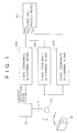
- Fig. 1 is an entire block diagram of a coordinate measuring machine according to the first embodiment.
- the coordinate measuring machine is composed of: a touch trigger probe 70 provided to be moved in three dimensional directions (the X-axis, Y-axis and Z-axis directions) by a three-dimensional moving system (not shown), and producing a position-detection signal from the positional relationship with an object W, in this case, a contact-detection signal by contacting the pre-measured object W; X-axis, Y-axis and Z-axis coordinate determining means 80X, 80Y and 80Z for determining the coordinates of the touch trigger probe in each axis direction; and a computing process means 60 for finding a size or configuration of the object W on the basis of the coordinate values P0x, P0y, and P0z which are respectively determined in the coordinate determining means 80X, 80Y and 80Z.
- the aforementioned touch trigger probe 70 has the same structure as that of the touch trigger probe shown in Figs. 14 and 15, so that the description is omitted. Note that the time from when the contacting portion 14A of the vibrator 14 contacts the object W to when the contact-detection signal is generated, namely, an elapsed time, is a touch trigger probe natural value and an approximately constant T1.
- each of the coordinate determining means 80X, 80Y and 80Z includes: a coordinate detecting means 30 for detecting a coordinate value P1 of the touch trigger probe 70 in an axis direction when the contact-detection signal is generated from the touch trigger probe 70; a velocity detecting means 40 for detecting a velocity V1 of the touch trigger probe 70 in an axis direction when the contact-detection signal is generated from the touch trigger probe 70; and a correction means 50 for finding a coordinate value P0, at the contact between the touch trigger prove 70 and the object W, from the coordinate value P1, the velocity V1 and the aforementioned elapsed time T1.
- the coordinate detecting means 30 consists of: a displacement detector 31 which detects a move position (a coordinate value P) of the touch trigger probe 70 in an axis direction; and a coordinates storage portion 32 which fetches and stores the coordinate value P1, at the time when the contact-detection signal is generated from the touch trigger probe 70, from the coordinate values P detected in the displacement detector 31.
- the velocity detecting means 40 consists of: a velocity detector 41, such as the tacho-generator, which detects a moving velocity of the three-dimensional moving system in an axis direction; and a velocity storage portion 42 which fetches and stores the detected velocity V1, at the time when the contact-detection signal is generated from the touch trigger probe 70, of the detected velocities V detected in the velocity detector 41.
- a velocity detector 41 such as the tacho-generator, which detects a moving velocity of the three-dimensional moving system in an axis direction
- a velocity storage portion 42 which fetches and stores the detected velocity V1, at the time when the contact-detection signal is generated from the touch trigger probe 70, of the detected velocities V detected in the velocity detector 41.
- the correction means 50 consists of: an elapsed time storage portion 51 which stores the natural delayed time of the touch trigger probe 70 T1 in advance; a correction amount computing portion 52 which computes a correction amount ⁇ P from the elapsed time T1, stored in the elapsed time storage portion 51, and the detected velocity V1 detected by the velocity detecting means 40; and a coordinate value correcting portion 53 which corrects the coordinate value P1, detected by the coordinate detecting means 30, with the correction amount ⁇ P, computed in the correction amount computing portion 52, to find the coordinate value P0 at the contact between the touch trigger probe 70 and the object W.
- the touch trigger probe 70 contacts the object W while moving in three-dimensional directions.
- each coordinate value P1 (of P1x, P1y and P1z) of the touch trigger probe 70 in each axis direction is detected and stored in the coordinate value detecting means 30 for each axis, and additionally, each velocity V1 (of V1x, V1y and V1z) of the touch trigger probe 70 in each axis direction is detected and stored in the velocity detecting means 40.
- the values (P, P1, P0, ⁇ P, V, V1, and K1) used in each means and computation have a dimension corresponding to a dimension of the coordinate measuring instrument.
- the expression can be written as follows.
- the touch trigger probe 70 contacts the object W and produces the contact-detection signal
- the coordinate value P1 and the velocity V1 of the touch trigger probe 70 are detected, and then the coordinate value P0 at the contact between the touch trigger probe 70 and the object W is obtained from the coordinate value P1, the velocity V1 and the elapsed time T1, so that the biased error caused by the elapsed time T1 and the velocity V1 of the touch trigger probe 70 can be corrected.
- the relative moving velocity V1 at the time when the contact-detection signal is generated has a vector component of the same dimension (three dimension) as that of the coordinate values P1 and P0. Additionally, each component value of the relative moving coordinate value P0 at the contact moment is obtained by using the elapsed time T1 and each component value of the relative moving coordinate value P1 and the relative moving velocity V1 at the time when the contact-detection signal is generated. That is to say the correction is carried out with the three-dimensional vector quantities with respect to three-dimensional space, therefore the above structure can be applied to the touch trigger probe having the elapsed time since the contact detection varying from measuring directions.
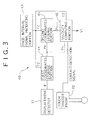
- the velocity detecting means 40 for detecting the velocity V1 of the touch trigger probe 70 when the contact-detection signal is output from the touch trigger probe 70 the velocity detector 41 and the velocity storage portion 42 are provided, but a structure as shown in Fig. 3 can be designed.
- the structure consists of: the displacement detector 31; a fixed interval signal producing portion 43; a first coordinates storage portion 44 which sequentially store the updating coordinate values P, detected by the displacement detector 31, at fixed intervals T2 of signals output from the fixed interval signal producing portion 43 to obtain a coordinate value P n ; a second coordinate storage portion 45 which stores a coordinate value P n-1 immediately antecedent to the coordinate value P n for the fixed interval T2; and a velocity computing portion 46 which finds the velocity V1 in producing the contact-detection signal from the fixed interval T2 and the coordinate values P n- and P n-1 respectively stored in the first and second coordinates storage portions 44 and 45.
- the mean velocity V n is output as an estimated value of the velocity V1 at the time when the contact-detection signal is generated.
- the values (P n , P n-1 , V n , and V1) used in each means and computation have a dimension corresponding to a dimension of the coordinate measuring instrument.
- the following expression can be derived.
- the natural delayed time of each touch trigger probe is stored in the elapsed time storage portion 51 in the plural, according to the type of touch trigger probe. And then, each time the touch trigger probe 70 is exchanged, the correction amount computing portion 52 may read the natural delayed time of the touch trigger probe after the replacement from the elapsed time storage portion 51 to compute the amount of correction.
- the correction can be carried out in consideration of the elapsed time varying with a type of the touch trigger probe, thereby achieving the measurement with high accuracy.
- the vibration type touch trigger probe is used, but another type touch trigger probe can be used: for example, a non-vibration measuring point contacts the object, and then the contact with the object is detected by electrically detecting the impact of the measuring point in the contact.
- the touch trigger probe 70 moves in three-dimensional directions, but the object can be moved, alternatively the touch trigger probe 70 and the object may be moved together also.
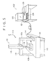
- Fig. 5 is a perspective view showing a structure of a manual coordinate measuring machine relating to the second embodiment.
- the coordinete measuring machine consists of a coordinete measuring machine body 101, and a host system 102 for fetching required measurement values from the coordinete measuring machine body 101 and processing the measurement values.
- the coordinete measuring machine body 101 is structured as follows. On an anti vibration platform 110, a surface plate 111 is mounted so that place the top surface thereof as a base surface for measuring is horizontal. An X-axis guide 113 is supported on the top ends of arm supporters 112a and 112b which respectively stand upright on the side ends of the surface plate 111. The arm supporter 112a is placed to move the bottom end thereof along a Y-axis guide 114 in the Y-axis direction. The arm supporter 112b is supported so that the bottom end thereof is moved in the Y-axis direction on the surface plate 111 by an air bearing.
- the X-axis guide 113 guides a Z-axis guide 115, extending in the vertical direction, in the X-axis direction.
- a Z-axis arm 116 is provided to move along the Z-axis guide 115.
- a contact type touch trigger probe 117 is equipped on the lower end of the Z-axis arm 116.
- the touch trigger probe 117 has the same structure as that of the aforementioned touch trigger probe shown in Fig. 13.
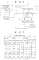
- Fig. 6 is a block diagram of the above coordinate measuring machine.
- the coordinete measuring machine body 101 has an XYZ-axes encoder 118 which outputs a movement indicating pules of each axis direction with the movement of the touch trigger probe 117 in the X-,Y-, and Z-axes.
- the host system 102 consists of a counter 120, a host computer 121, a monitor 122, a printer 123 and a keyboard 124.
- the counter 120 calculates a pulse signal of each axis, output from the XYZ axes encoder 118, according to an axis, and latches the calculated value of each axis in response to the contact-detection signal output from the touch trigger probe 117 when the touch trigger probe 117 contacts the object W.
- the host computer 121 inputs the calculated value latched in the counter 120, and converts it into a present coordinate value of the touch trigger probe 117.
- the host computer 121 detects a moving direction and a moving velocity of the touch trigger probe 117 from the calculated value in the counter 120 which is sampled at regular intervals, and additionally, detects the contact-detection signal output from the touch trigger probe 117 to detect the contact velocity at the moment of contact between the touch trigger probe 117 and the object W.
- the host computer 121 includes a correction table 125.
- the correction table 125 is configured with electrically erasable EEPROM or the like, and as shown in Fig.
- the host computer 121 structures a coordinate value detecting means, a velocity detecting means and a correction means.
- the touch trigger probe 117 or the Z-axis arm 116 is grasped, and the touch trigger probe 117 is moved by a hand operation so that the end ball thereof contacts each part of the object W, thereby measuring each part of the object W.
- the measurement error may be contributed by the contact velocity, so that the correction table 125 is determined in advance through the following processes.
- the object W is secured on the surface plate 111.
- the touch trigger probe 117 is manually moved to come in contact with a specified face of the object W. in this state, the touch trigger probe 117 is in a free state not to deform.
- each axis is fixed to determine the X-axis, Y-axis and Z-axis coordinates with precision by a well-known scale-correction means using a laser interferometer or a correction probe.
- the indicated values are corrected to the measured values.
- the touch trigger probe 117 attached to the Z-axis arm 116 repeatedly contacts on the specified face of the object W while the contact velocity is changed variously.
- the relationship between the contact velocity and the measured value in the above step is stored in the host computer 121.
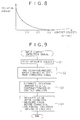
- the correction table 125 showing the relationship between the contact velocity and the amount of deviation as shown in Fig. 7, can be created from the above curve line. Note that where the relationship between the contact velocity and the amount of deviation has no dependence on the contact direction from the viewpoint of the structure of the touch trigger probe 117, the amount of deviation is not needed to be determined in each axis.
- Fig. 9 is a flow chart showing processes of the host computer 121 in the actual measurement.
- the contact-detection signal is input from the touch trigger probe 117, whereupon the measured values (X-axis, Y-axis and Z-axis coordinate values) at the time of inputting the contact-detection signal are fetched (S1).
- the amount of deviation with respect to the contact velocity is determined from the correction table 125 (S2). In this time, for example, when the contact velocity is 1.3 mm/s and the contact velocity registered in the correction table 125 is 0.5, 1.0, 1.5, . , mm/s, the amount of deviation is calculated from the amount of deviation of 1.0 mm/s and 1.5 mm/s in the correction table 125 by, for example, linear interpolation.
- the contact velocity in each axis direction is calculated, and then the amount of deviation is determined with respect to each of the calculated contact-velocities.
- the determined amount of deviation is distributed to the component of each axis (of X-, Y- and Z-axes) direction on the basis of the contact direction (S3).
- the value as a result of addition (or subtractions) of the fetched measured value before correction and the amount of deviation of each axis is found as the measured value after the correction (S4). That is to say, the amount of deviation of each axis as the amount of correction is added to (or subtracted from) the measured value before correction. Thereby achieving the accurate measurement independent of the contact velocity.
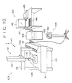
- Fig. 10 shows an example when the present invention is applied to a CNC coordinate measuring machine.
- the coordinate measuring machine is provided with: a coordinete measuring machine body 103; a host system 104; a controller 105 for controlling the driving of the coordinete measuring machine body 103 and fetching the necessary measured values from the coordinete measuring machine body 103; and a console panel 106 for manually controlling the coordinete measuring machine body 103 via the controller 105.
- the basic structure of the coordinete measuring machine 103 is similar to the structure of the coordinete measuring machine 101 in Fig. 5, so that the same reference numerals will be used to designate the parts corresponding to the coordinete measuring machine 101, and the description will be omitted or simplified.
- the lower end of the arm supporter 112a is driven in the Y-axis direction by a Y-axis driving system 131.
- the X-axis guide 113 drives the Z-axis guide 115, extending in the vertical direction, in the X-axis direction.
- the Z-axis arm 116 is provided in the Z-axis guide 115 to be driven along the Z-axis guide 115.
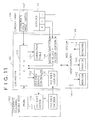
- Fig. 11 is a block diagram of this coordinate measuring machine.
- the coordinete measuring machine body 103 has an XYZ-axes motor 132 for driving the touch trigger probe 117 in the X-axis, Y-axis and Z-axis directions.
- the console panel 106 is provided thereon with a joystick 161 for driving the touch trigger probe 117 of the coordinete measuring machine body 103 in the X-axis, Y-axis and Z-axis directions by a hand operation, and a coordinate value input switch 162 for inputting the X-axis, Y-axis and Z-axis coordinates of the present position of the touch trigger probe 117 into the controller 105.
- a joystick 161 for driving the touch trigger probe 117 of the coordinete measuring machine body 103 in the X-axis, Y-axis and Z-axis directions by a hand operation
- a coordinate value input switch 162 for inputting the X-axis, Y-axis and Z-axis coordinates of the present position of the touch trigger probe 117 into the controller 105.
- a CPU 151 is provided in the controller 105 to perform the driving control of the probe 117, the fetching control of the calculated values and so on. More specifically, an XYZ-axes driving controller 152 drives the XYZ-axes motor 132 of the coordinete measuring machine body 103 on the basis of the instruction of the CPU 151, and additionally an XYZ-axes counter 153 counts pulse signals, corresponding to each axis, output from the XYZ-axes encoder 118 to find the present position and send it as feedback to the CPU 151.
- the CPU 151 controls the driving of the touch trigger probe 117 on the basis of the feedback information.
- the CPU 151 stops the XYZ-axes motor 132 in response to the contact-detection signal from the touch trigger probe 117.
- a voltage value of a potentiometer which corresponds to each axis and responds to a tilt angle and a tilting direction of the joystick 162, is output from the console panel 106.
- a moving-direction and velocity deciding portion 154 of the controller 105 decides the moving direction and the moving velocity of the probe 117 in response to the above voltage value of each axis.
- the aforementioned correction table 125 is provided in the controller 105.
- the CPU 151 corrects the measured value, fetched in the CPU 151, to read the correction table 125 on the basis of the contact direction and the contact velocity of the touch trigger probe 117 and the object W, so that the measurement can be achieved with high precision even in an automatic measurement for a small hole where a sufficient contact velocity is not available, or the manual measurement using the console panel 106.
- the correction table 125 can be also created by the following method.
- Fig. 12 shows the explanation of the creating method.
- the contact direction cannot be defined in multi directions and the touch trigger probe 117 cannot contact the object at a specific velocity, so that the correction table 125 is created as follows.
- the correction table 125 can be created with precision without using the laser interferometer or the like.
- the relationship between the contact velocity (the relative moving velocity) of the touch trigger prove 117 and the object and the amount of deviation (the amount of correction) derived from this contact velocity is stored as a function in a storage means in advance.
- the amount of deviation (the amount of correction) is found to substitute the contact velocity (the relative moving velocity at the time when the contact-detection signal is generated) into the function by a computing means.
- the relative moving coordinate value at the time when the contact-detection signal is generated may be corrected with this amount of deviation.
- the structure in which only the touch trigger probe is moved in the three-dimensional directions is described, but the object W can be moved, alternatively both of them (the touch trigger probe 117 and the object W) may be moved.
- the structure in which the touch trigger probe and the object are moved in the three-dimensional directions is described, but the touch trigger probe and the object may be relatively moved in a one-dimensional direction or two-dimensional directions.
- the touch trigger probe is used is explained in the first to third embodiments, but a non-contacting probe can be used.
- the non-contacting probe which has an optical displacement sensor for moving an objective lens close to and apart from a measured face of the object to focus a focal point of the objective lens on the measured face, or the non-contacting probe of a camera or the like, can be used when the size of the object is measured.
- the measurement of the size or configuration of the object is described, but the surface shape of the object, such as roughness, swell, and configuration (outline or roundness), can be measured from the determined coordinate values.
- the measuring method and the measuring instrument of the present invention even in the complicated measurement which requires changing the measuring velocity in response to the substance of measuring, the biased error caused by the measuring velocity is corrected, and additionally the high-accurate and efficient measurement is achieved.
Abstract
Description


Claims (19)
- A measuring method, wherein a measured object and a probe, producing a position-detection signal by the relation with the object, are relatively moved, and a relative moving coordinate value of the probe and the object is detected in response to the position-detection signal output from the probe, and then at least one of a size and a surface shape of the object is measured on the basis of the relative moving coordinate value, said measuring method comprising the steps of:detecting the relative moving coordinate value of the probe and the object, and a relative moving velocity of the probe and the object in response to the position-detection signal from the probe; andcorrecting the relative moving coordinate value in said detecting step with the amount of correction derived from the relative moving velocity in said detecting step.
- A measuring method, wherein a touch trigger probe and a measured object contacts during the relative movement, and a relative moving coordinate value of the touch trigger probe and the object is detected in response to a contact-detection signal, produced from the touch trigger probe at the time of the contact between the touch trigger probe and the object, and then at least one of a size and a surface shape of the object is measured on the basis of the relative moving coordinate value, said measuring method comprising the steps of:detecting the relative moving coordinate value of the touch trigger probe and the object, and a relative moving velocity of the touch trigger probe and the object, at the time when the contact-detection signal is generated from the touch trigger probe; andcorrecting the relative moving coordinate value, at the time when the contact-detection signal is generated, with the amount of correction derived from the relative moving velocity at the time when the contact-detection signal is generated.
- The measuring method according to claim 2,wherein a natural elapsed time of the touch trigger probe, from the contact between the touch trigger probe and the object until the contact-detection signal is generated, is stored in advance; andwherein the amount of correction is computed from the relative moving velocity, at the time when the contact-detection signal is generated, and the elapsed time in order that the relative moving coordinate value at the time when the contact-detection signal is generated is corrected with the amount of correction.
- The measuring method according to claim 3,wherein the relative moving coordinate value at the time when the contact-detection signal is generated is any one of a two-dimensional coordinate value and the three-dimensional coordinate value;wherein the relative moving velocity at the time when the contact-detection signal is generated has a lager number of vector components than the same number of dimensions as the two-dimensional coordinate value or the three-dimensional coordinate value; andwherein the relative moving coordinate value at the time when the contact-detection signal is generated is corrected with the elapsed time and each component value of the relative moving velocities at the time when the contact-detection signal is generated.
- The measuring method according to any one of claims 3 and 4,wherein the natural elapsed time of each touch trigger probe is stored according to the type of touch trigger probe in advance; andwherein the amount of correction is computed with the natural elapsed time of the touch trigger probe each time the touch trigger probe is changed.
- The measuring method according to claim 2,wherein the relationship between the relative moving velocity of the touch trigger probe and the object and the amount of correction, derived from the relative moving velocity, is stored in a correction table in advance; andwherein the amount of correction, corresponding to the relative moving velocity at the time when the contact-detection signal is generated, is found from the correction table in order that the relative moving coordinate value at the time when the contact-detection signal is generated is corrected with the amount of correction.
- The measuring method according to claim 6,wherein the relative moving coordinate value at the time when the contact-detection signal is generated is a coordinate value in two-dimension or three-dimension;wherein the amount of correction in two-dimension or three-dimension is stored in the correction table to correspond to the relative moving velocity at the time when the contact-detection signal is generated; andwherein the amount of correction in two-dimension or three-dimension, corresponding to the relative moving velocity at the time when the contact-detection signal is generated, is selected from the correction table.
- The measuring method according to any one of claims 6 and 7, wherein the amount of correction, corresponding to the relative moving velocity at the time when the contact-detection signal is generated, is computed with the amount of correction, corresponding to relative moving velocities positioned antecedent and subsequent to the relative moving velocity at the time when the contact-detection signal is generated, and with the relative moving velocities which are positioned antecedent and subsequent to the relative moving velocity at the time when the contact-detection signal is generated, when the relative moving velocity, at the time when the contact-detection signal is generated, is in the relative moving velocities stored in said correction table.
- The measuring method according to any one of claims 6, 7, and 8,wherein the relationship between the relative moving velocity of the touch trigger probe and the object and the amount of correction derived from the relative moving velocity is stored in the correction table in advance according to the type of trigger probe used ; andwherein the amount of correction is computed with the relationship between the amount of correction and the relative moving velocity corresponding to the type of touch trigger probe each time the touch trigger probe is exchanged.
- The measuring method according to claim 2,wherein the relationship between the relative moving velocity of the touch trigger probe and the object and the amount of correction derived from the relative moving velocity is approximated with a function in advance; andwherein the amount of correction is found by substituting the relative moving velocity, at the time when the contact-detection signal is generated, into the function in order that the relative moving coordinate value at the time when the contact-detection signal is generated is corrected with the found amount of correction.
- The measuring method according to any one of claims 2 to 10,wherein the relative moving coordinate value of the touch trigger probe and the object is detected at regular time-intervals; andwherein the relative moving velocity at the time when the contact-detection signal is generated is estimated from the regular time-intervals and the more than two relative moving coordinate values detected.
- A measuring instrument, wherein a measured object and a probe, producing a position-detection signal by the relation with the object, are relatively moved, and a relative moving coordinate value of the probe and the object is detected in response to the position-detection signal output from the probe, and then at least one of a size and a surface shape of the object is measured on the basis of the relative moving coordinate value, said measuring instrument comprising:a coordinate value detecting means for detecting the relative moving coordinate value of the probe and the object in response to the position-detection signal from the probe;a velocity detecting means for detecting a relative moving velocity of the probe and the object when said coordinate value detecting means detects the relative moving coordinate value; anda correction means for correcting the relative moving coordinate value at the contact with the amount of correction derived from the relative moving velocity at the moment of contact.
- A measuring instrument, wherein a touch trigger probe and a measured object contact during the relative movement, and a relative moving coordinate value of the touch trigger probe and the object is detected in response to a contact-detection signal, produced from the touch trigger probe at the contact between the touch trigger probe and the object, and then a size or a surface shape of the object is measured on the basis of the relative moving coordinate value, said measuring instrument comprising:a coordinate value detecting means for detecting a relative moving coordinate value of the touch trigger probe and the object at the time when the contact-detection signal is generated from the touch trigger probe;a velocity detecting means for detecting a relative moving velocity of the touch trigger probe and the object at the time when the contact-detection signal is generated from the touch trigger probe; anda correction means for correcting the relative moving coordinate value, at the time when the contact-detection signal is generated, with the amount of correction derived from the relative moving velocity at the time when the contact-detection signal is generated.
- The measuring instrument according to claim 13, wherein said correction means has an elapsed time storage portion storing in advance a natural elapsed time of the touch trigger probe, from the contact between the touch trigger probe and the object until the contact-detection signal is generated, a correction amount computing portion computing the amount of correction from the elapsed time and the relative moving velocity at the time when the contact-detection signal is generated, and a coordinate value correcting portion correcting the relative moving coordinate value, at the time when the contact-detection signal is generated, with the amount of correction computed in said correction amount computing portion.
- The measuring instrument according to claim 14,wherein said elapsed time storage portion stores the natural elapsed time of the touch trigger probe according to the type of trigger probe used; andwherein said correction amount computing portion computes the amount of correction by reading the natural elapsed time of the touch trigger probe from said elapsed time storage portion each time the touch trigger probe is exchanged.
- The measuring instrument according to claim 13, wherein said correction means has a correction table storing in advance the relationship between the relative moving velocity of the touch trigger probe and the object and the amount of correction derived from the relative moving velocity, and an error correction portion finding the amount of correction, corresponding to the relative moving velocity at the time when the contact-detection signal is generated, from said correction table, and correcting the relative moving coordinate value, at the time when the contact-detection signal is generated, with the found amount of correction.
- The measuring instrument according to claim 16,wherein said correction table stores the relationship between the relative moving velocity of the touch trigger probe and the object and the amount of correction derived from the relative moving velocity, according to the type of trigger probe used; andwherein said error correction portion computing the amount of correction with the relationship between the amount of correction and the relative moving velocity, corresponding to the type of trigger probe each after the touch trigger probe is exchanged.
- The measuring instrument according to claim 13, wherein said correction means has a storage portion storing in advance the relationship between the relative moving velocity of the touch trigger probe and the object and the amount of correction derived from the relative moving velocity with an approximated function, and a computing portion finding the amount of correction to substitute the relative moving velocity, at the time when the contact-detection signal is generated, into the function.
- The measuring instrument according to claims 13 to 18, wherein said velocity detecting means has a displacement detector detecting the relative moving coordinate value of the touch trigger probe and the object, a fixed interval signal producing portion, a first coordinate storage portion for sequentially storing the relative moving coordinate values, detected in said displacement detector, at fixed intervals of signals, output from said fixed interval signal producing portion, and obtaining the relative moving coordinate value, a second coordinate storage portion for storing a relative moving coordinate value antecedent to the relative moving coordinate value, obtained by said first coordinate storage portion, for the fixed interval, and a velocity computing portion for finding the relative moving velocity, at the time when the contact-detection signal is generated, from the fixed interval and the relative moving coordinate values stored in said first and second coordinate storage portion.
Applications Claiming Priority (6)
| Application Number | Priority Date | Filing Date | Title |
|---|---|---|---|
| JP2657497 | 1997-02-10 | ||
| JP2657497 | 1997-02-10 | ||
| JP26574/97 | 1997-02-10 | ||
| JP5493797 | 1997-03-10 | ||
| JP54937/97 | 1997-03-10 | ||
| JP5493797 | 1997-03-10 |
Publications (2)
| Publication Number | Publication Date |
|---|---|
| EP0858015A1 true EP0858015A1 (en) | 1998-08-12 |
| EP0858015B1 EP0858015B1 (en) | 2003-05-07 |
Family
ID=26364378
Family Applications (1)
| Application Number | Title | Priority Date | Filing Date |
|---|---|---|---|
| EP98102288A Expired - Lifetime EP0858015B1 (en) | 1997-02-10 | 1998-02-10 | Measuring method and measuring instrument with a trigger probe |
Country Status (4)
| Country | Link |
|---|---|
| US (1) | US6044569A (en) |
| EP (1) | EP0858015B1 (en) |
| CN (1) | CN1136430C (en) |
| DE (1) | DE69814198T2 (en) |
Cited By (6)
| Publication number | Priority date | Publication date | Assignee | Title |
|---|---|---|---|---|
| EP0971308A1 (en) * | 1998-07-06 | 2000-01-12 | Thomas Dr. Riedel | Three-dimensional input device and method for digitising objects |
| GB2328025B (en) * | 1997-07-18 | 2001-11-07 | Renishaw Plc | Method of measuring workpieces using a coordinate positioning machine |
| WO2003001149A1 (en) * | 2001-06-21 | 2003-01-03 | Werth Messtechnik Gmbh | Method and device for detecting an object point on a object |
| EP1382934A2 (en) * | 2002-07-09 | 2004-01-21 | Mitutoyo Corporation | Surface profile measuring instrument and surface profile measuring method |
| US9250055B2 (en) | 2014-05-09 | 2016-02-02 | Mitutoyo Corporation | High speed contact detector for measurement sensors |
| US20170160066A1 (en) * | 2014-08-28 | 2017-06-08 | Carl Zeiss Industrielle Messtechnik Gmbh | Method for single-point scanning of a workpiece and coordinate measuring machine |
Families Citing this family (50)
| Publication number | Priority date | Publication date | Assignee | Title |
|---|---|---|---|---|
| GB2336433B (en) * | 1998-04-14 | 2002-02-06 | Mitutoyo Corp | Touch signal probe |
| JP3633788B2 (en) * | 1998-07-13 | 2005-03-30 | 株式会社ミツトヨ | measuring device |
| DE19848642A1 (en) * | 1998-10-22 | 2000-04-27 | Heidenhain Gmbh Dr Johannes | Temperature-dependent variation compensation method for machine tool or robot geometry corrects user input commands before conversion from input coordinate system into machine coordinate system |
| US6708420B1 (en) * | 1999-01-06 | 2004-03-23 | Patrick M. Flanagan | Piezoelectric touch probe |
| JP2000199710A (en) * | 1999-01-06 | 2000-07-18 | Mitsutoyo Corp | Structure for detecting contact site of touch signal probe |
| US6229297B1 (en) * | 1999-06-30 | 2001-05-08 | Hewlett-Packard Company | Device for determining the position of an object relative to a surface |
| US6704684B2 (en) * | 1999-10-22 | 2004-03-09 | Carl-Zeiss-Stiftung | Method for determining measuring points on a workpiece and a measuring system therefor |
| US6460261B1 (en) * | 1999-11-18 | 2002-10-08 | Mitutoyo Corporation | V-groove shape measuring method and apparatus by using rotary table |
| JP2001264050A (en) * | 2000-03-14 | 2001-09-26 | Mitsutoyo Corp | Minute shape measuring apparatus |
| US6442857B1 (en) * | 2000-11-10 | 2002-09-03 | Toto Ltd. | Portable surface inspector |
| EP1241436B1 (en) * | 2001-03-14 | 2014-11-19 | Tesa Sa | Coordinate measuring machine and method for introducing a command to change the measurement mode in this machine |
| US7519493B2 (en) * | 2002-02-14 | 2009-04-14 | Faro Technologies, Inc. | Portable coordinate measurement machine with integrated line laser scanner |
| US7881896B2 (en) | 2002-02-14 | 2011-02-01 | Faro Technologies, Inc. | Portable coordinate measurement machine with integrated line laser scanner |
| US6957496B2 (en) * | 2002-02-14 | 2005-10-25 | Faro Technologies, Inc. | Method for improving measurement accuracy of a portable coordinate measurement machine |
| US6973734B2 (en) * | 2002-02-14 | 2005-12-13 | Faro Technologies, Inc. | Method for providing sensory feedback to the operator of a portable measurement machine |
| US6952882B2 (en) | 2002-02-14 | 2005-10-11 | Faro Technologies, Inc. | Portable coordinate measurement machine |
| USRE42082E1 (en) | 2002-02-14 | 2011-02-01 | Faro Technologies, Inc. | Method and apparatus for improving measurement accuracy of a portable coordinate measurement machine |
| US7246030B2 (en) * | 2002-02-14 | 2007-07-17 | Faro Technologies, Inc. | Portable coordinate measurement machine with integrated line laser scanner |
| US7043847B2 (en) * | 2002-02-14 | 2006-05-16 | Faro Technologies, Inc. | Portable coordinate measurement machine having on-board power supply |
| US7376261B2 (en) | 2003-11-25 | 2008-05-20 | Mitutoyo Corporation | Surface scan measuring device and method of forming compensation table for scanning probe |
| DE102005011285A1 (en) * | 2004-05-27 | 2005-12-15 | Dr. Johannes Heidenhain Gmbh | Apparatus and method for coordinate measurement |
| GB0501690D0 (en) | 2005-01-27 | 2005-03-02 | Renishaw Plc | Articulating device |
| EP2105698A1 (en) * | 2005-04-11 | 2009-09-30 | Faro Technologies, Inc. | Three-dimensional coordinate measuring device |
| JP4372759B2 (en) * | 2006-02-10 | 2009-11-25 | 株式会社ミツトヨ | Shape measuring apparatus, shape measuring method, and shape measuring program |
| JP5221004B2 (en) * | 2006-05-25 | 2013-06-26 | 株式会社ミツトヨ | Measuring device, surface texture measuring method, and surface texture measuring program |
| JP5189806B2 (en) * | 2006-09-07 | 2013-04-24 | 株式会社ミツトヨ | Surface shape measuring device |
| GB0703423D0 (en) * | 2007-02-22 | 2007-04-04 | Renishaw Plc | Calibration method and apparatus |
| US8122610B2 (en) * | 2008-03-28 | 2012-02-28 | Hexagon Metrology, Inc. | Systems and methods for improved coordination acquisition member comprising calibration information |
| US8082673B2 (en) | 2009-11-06 | 2011-12-27 | Hexagon Metrology Ab | Systems and methods for control and calibration of a CMM |
| CA2766906C (en) * | 2009-06-30 | 2019-03-05 | Hexagon Metrology Ab | Coordinate measurement machine with vibration detection |
| DE102009049534A1 (en) * | 2009-10-06 | 2011-04-07 | Carl Zeiss Industrielle Messtechnik Gmbh | Coordinate measuring machine with position change sensors |
| DE102010018250A1 (en) * | 2010-04-23 | 2011-10-27 | Carl Zeiss Industrielle Messtechnik Gmbh | Method for measuring coordinates on workpieces on a coordinate measuring machine |
| JP5557620B2 (en) * | 2010-06-29 | 2014-07-23 | 株式会社ミツトヨ | Shape measuring device |
| JP5523995B2 (en) * | 2010-09-03 | 2014-06-18 | 株式会社ミツトヨ | measuring device |
| JP5936357B2 (en) * | 2012-01-06 | 2016-06-22 | 株式会社ミツトヨ | Attitude detector, contact probe, and multi-sensing probe |
| JP6030339B2 (en) * | 2012-05-17 | 2016-11-24 | 株式会社ミツトヨ | Shape measuring device |
| CN102814707B (en) * | 2012-08-14 | 2015-02-18 | 西安理工大学 | Device and method for determining trigger stroke of trigger sensor |
| DE102012215215A1 (en) * | 2012-08-27 | 2014-05-28 | Inb Vision Ag | Method and device for detecting deviations of a surface of an object |
| JP2014130091A (en) * | 2012-12-28 | 2014-07-10 | Canon Inc | Measurement device and measurement method |
| CN103727869A (en) * | 2013-09-22 | 2014-04-16 | 雷孔成 | Pocket three-coordinate length measuring instrument |
| US20150178484A1 (en) | 2013-12-20 | 2015-06-25 | Mitutoyo Corporation | Remote Accessory Management in a Programming Environment for a Progammable Metrology System |
| US9606525B2 (en) | 2013-12-23 | 2017-03-28 | Mitutoyo Corporation | Remote accessory for generating customized and synchronized reference notes for a programmable metrology system |
| CN103995588B (en) * | 2014-05-14 | 2017-01-18 | 沈文策 | Displacement distance obtaining method and device and displacement distance application method and device |
| US9759540B2 (en) | 2014-06-11 | 2017-09-12 | Hexagon Metrology, Inc. | Articulating CMM probe |
| JP6212148B2 (en) * | 2016-02-26 | 2017-10-11 | 株式会社ミツトヨ | Measuring probe |
| JP6216400B2 (en) * | 2016-02-26 | 2017-10-18 | 株式会社ミツトヨ | Measuring probe |
| CN106482702A (en) * | 2016-09-26 | 2017-03-08 | 昆山工研院新型平板显示技术中心有限公司 | A kind of method and device of test substrate warp |
| EP3470777B1 (en) | 2017-10-10 | 2021-09-29 | Hexagon Technology Center GmbH | System, method and computer program product for determining a state of a tool positioning machine |
| CN110296674B (en) * | 2019-06-12 | 2021-07-30 | 智久(厦门)机器人科技有限公司 | Distance error compensation method and device for depth camera and storage medium |
| DE102019122655A1 (en) * | 2019-08-22 | 2021-02-25 | M & H Inprocess Messtechnik Gmbh | Measuring system |
Citations (6)
| Publication number | Priority date | Publication date | Assignee | Title |
|---|---|---|---|---|
| US4362978A (en) * | 1980-10-27 | 1982-12-07 | Unimation, Inc. | Control system for manipulator apparatus |
| EP0147529B1 (en) * | 1983-10-11 | 1988-04-20 | Dr. Johannes Heidenhain GmbH | Process for the determination of the position and/or dimensions of an object to be tested, and device for carrying it out |
| EP0073495B1 (en) * | 1981-08-29 | 1989-03-15 | Toshiba Kikai Kabushiki Kaisha | Method and apparatus for measuring a workpiece |
| EP0420416A2 (en) * | 1989-09-09 | 1991-04-03 | Renishaw plc | Method and apparatus of datuming a coordinate positioning machine |
| WO1992020996A1 (en) * | 1991-05-21 | 1992-11-26 | Renishaw Metrology Limited | A method of measuring workpieces using a surface contacting measuring probe |
| US5425180A (en) * | 1992-02-15 | 1995-06-20 | Carl-Zeiss-Stiftung | Method for coordinate measurement of workpieces |
Family Cites Families (6)
| Publication number | Priority date | Publication date | Assignee | Title |
|---|---|---|---|---|
| GB2045437B (en) * | 1979-03-30 | 1984-02-08 | Renishaw Electrical Ltd | Coordinate measuring machine |
| DE3523188A1 (en) * | 1985-06-28 | 1987-01-08 | Zeiss Carl Fa | CONTROL FOR COORDINATE MEASURING DEVICES |
| NO911774D0 (en) * | 1991-05-06 | 1991-05-06 | Sensonor As | DEVICE FOR ENCAPLING A FUNCTIONAL ORGANIZATION AND PROCEDURE FOR PRODUCING THE SAME. |
| JP2902205B2 (en) * | 1992-03-06 | 1999-06-07 | 株式会社ミツトヨ | Spatial error correction device |
| DE4245012B4 (en) * | 1992-04-14 | 2004-09-23 | Carl Zeiss | Method for measuring shaped elements on a coordinate measuring machine |
| US5657549A (en) * | 1995-10-04 | 1997-08-19 | Shen; Yin-Lin | Method of improving accuracy of touch trigger probe |
-
1998
- 1998-02-10 DE DE69814198T patent/DE69814198T2/en not_active Expired - Fee Related
- 1998-02-10 US US09/021,543 patent/US6044569A/en not_active Expired - Fee Related
- 1998-02-10 CN CNB981044166A patent/CN1136430C/en not_active Expired - Fee Related
- 1998-02-10 EP EP98102288A patent/EP0858015B1/en not_active Expired - Lifetime
Patent Citations (6)
| Publication number | Priority date | Publication date | Assignee | Title |
|---|---|---|---|---|
| US4362978A (en) * | 1980-10-27 | 1982-12-07 | Unimation, Inc. | Control system for manipulator apparatus |
| EP0073495B1 (en) * | 1981-08-29 | 1989-03-15 | Toshiba Kikai Kabushiki Kaisha | Method and apparatus for measuring a workpiece |
| EP0147529B1 (en) * | 1983-10-11 | 1988-04-20 | Dr. Johannes Heidenhain GmbH | Process for the determination of the position and/or dimensions of an object to be tested, and device for carrying it out |
| EP0420416A2 (en) * | 1989-09-09 | 1991-04-03 | Renishaw plc | Method and apparatus of datuming a coordinate positioning machine |
| WO1992020996A1 (en) * | 1991-05-21 | 1992-11-26 | Renishaw Metrology Limited | A method of measuring workpieces using a surface contacting measuring probe |
| US5425180A (en) * | 1992-02-15 | 1995-06-20 | Carl-Zeiss-Stiftung | Method for coordinate measurement of workpieces |
Non-Patent Citations (3)
| Title |
|---|
| MULLER G: "KOORDINATEN-MESSGERATE NACHRUSTEN RETROFITTING COORDINATE MEASURING EQUIPMENT", 1 March 1995, WERKSTATT UND BETRIEB, VOL. 128, NR. 3, PAGE(S) 161/162, 165/166, XP000508465 * |
| WECK M ET AL: "ON-LINE-VERMESSUNG VON WERKSTUCKEN IM ROBOTERGREIFER ON-LINE MEASUREMENT OF COMPONENTS IN THE ROBOT GRIPPER", 1 July 1994, ZWF ZEITSCHRIFT FUR WIRTSCHAFTLICHE FERTIGUNG UND AUTOMATISIERUNG, VOL. 89, NR. 7/08, PAGE(S) 400/401, XP000457890 * |
| WOCKE P: "KMG AUTOMATISCH PROGRAMMIEREN GENERIERUNG, VISUALISIERUNG UND MODIFIZIERUNG VON ANTASTPUNKTEN UND VERFAHRWEGEN", 1 April 1994, F & M. FEINWERKTECHNIK MIKROTECHNIK MESSTECHNIK, VOL. 102, NR. 4, PAGE(S) 181 - 186, XP000446402 * |
Cited By (9)
| Publication number | Priority date | Publication date | Assignee | Title |
|---|---|---|---|---|
| GB2328025B (en) * | 1997-07-18 | 2001-11-07 | Renishaw Plc | Method of measuring workpieces using a coordinate positioning machine |
| EP0971308A1 (en) * | 1998-07-06 | 2000-01-12 | Thomas Dr. Riedel | Three-dimensional input device and method for digitising objects |
| WO2003001149A1 (en) * | 2001-06-21 | 2003-01-03 | Werth Messtechnik Gmbh | Method and device for detecting an object point on a object |
| EP1382934A2 (en) * | 2002-07-09 | 2004-01-21 | Mitutoyo Corporation | Surface profile measuring instrument and surface profile measuring method |
| EP1382934A3 (en) * | 2002-07-09 | 2005-06-29 | Mitutoyo Corporation | Surface profile measuring instrument and surface profile measuring method |
| US7100429B2 (en) | 2002-07-09 | 2006-09-05 | Mitutoyo Corporation | Surface profile measuring instrument and surface profile measuring method |
| US9250055B2 (en) | 2014-05-09 | 2016-02-02 | Mitutoyo Corporation | High speed contact detector for measurement sensors |
| US20170160066A1 (en) * | 2014-08-28 | 2017-06-08 | Carl Zeiss Industrielle Messtechnik Gmbh | Method for single-point scanning of a workpiece and coordinate measuring machine |
| US10508895B2 (en) * | 2014-08-28 | 2019-12-17 | Carl Zeiss Industrielle Messtechnik Gmbh | Method for single-point scanning of a workpiece and coordinate measuring machine |
Also Published As
| Publication number | Publication date |
|---|---|
| DE69814198D1 (en) | 2003-06-12 |
| CN1136430C (en) | 2004-01-28 |
| CN1191301A (en) | 1998-08-26 |
| DE69814198T2 (en) | 2004-04-08 |
| EP0858015B1 (en) | 2003-05-07 |
| US6044569A (en) | 2000-04-04 |
Similar Documents
| Publication | Publication Date | Title |
|---|---|---|
| US6044569A (en) | Measuring method and measuring instrument | |
| US7660688B2 (en) | Surface-profile measuring instrument | |
| US6412329B1 (en) | Method of and apparatus for reducing vibrations on probes carried by coordinate measuring machines | |
| US7286949B2 (en) | Method of error correction | |
| EP1760422B1 (en) | Surface profile measuring instrument | |
| JP2911753B2 (en) | A calibration method that detects and compensates for different contact force ratios in a multi-coordinate contact system | |
| EP2013571B1 (en) | Method of error correction | |
| JP2988588B2 (en) | Position measuring device | |
| EP1792139B2 (en) | The use of surface measurement probes | |
| US20070271803A1 (en) | Measuring apparatus, method of measuring surface texture and computer readable medium having program for measuring surface texture | |
| US20090150108A1 (en) | Hysteresis compensation in a coordinate measurement machine | |
| CN107883882B (en) | Measuring device for an optical measuring system | |
| JPH07324928A (en) | Method for measuring coordinate of surface of workpiece | |
| JP2005121370A (en) | Surface shape measuring apparatus and method | |
| JP3531882B2 (en) | Measurement error correction device for CMM | |
| JP2005037197A (en) | Contact type surface shape measuring device and measuring method | |
| JP3820357B2 (en) | Measuring method and measuring apparatus | |
| JP2005114549A (en) | Surface profile measuring apparatus and method | |
| JPH10311715A (en) | Measurement method and device | |
| US20190277615A1 (en) | Measurement apparatus | |
| JP2579726B2 (en) | Contact probe | |
| JPH11281306A (en) | Calibrated-value detection method for coordinate-measuring machine and calibration method for shape data using the same calibrated data | |
| JPH11352006A (en) | Unit for detecting amount of displacement and method for measuring amount of displacement | |
| JPH04291130A (en) | Deformation test robot | |
| JPH0926308A (en) | Noncontact three-dimensional displacement detection apparatus |
Legal Events
| Date | Code | Title | Description |
|---|---|---|---|
| PUAI | Public reference made under article 153(3) epc to a published international application that has entered the european phase |
Free format text: ORIGINAL CODE: 0009012 |
|
| AK | Designated contracting states |
Kind code of ref document: A1 Designated state(s): DE FR GB |
|
| AX | Request for extension of the european patent |
Free format text: AL;LT;LV;MK;RO;SI |
|
| 17P | Request for examination filed |
Effective date: 19981023 |
|
| AKX | Designation fees paid |
Free format text: DE FR GB |
|
| RBV | Designated contracting states (corrected) |
Designated state(s): DE FR GB |
|
| 17Q | First examination report despatched |
Effective date: 20011029 |
|
| GRAH | Despatch of communication of intention to grant a patent |
Free format text: ORIGINAL CODE: EPIDOS IGRA |
|
| GRAH | Despatch of communication of intention to grant a patent |
Free format text: ORIGINAL CODE: EPIDOS IGRA |
|
| GRAA | (expected) grant |
Free format text: ORIGINAL CODE: 0009210 |
|
| AK | Designated contracting states |
Designated state(s): DE FR GB |
|
| REG | Reference to a national code |
Ref country code: GB Ref legal event code: FG4D |
|
| REF | Corresponds to: |
Ref document number: 69814198 Country of ref document: DE Date of ref document: 20030612 Kind code of ref document: P |
|
| ET | Fr: translation filed | ||
| PLBE | No opposition filed within time limit |
Free format text: ORIGINAL CODE: 0009261 |
|
| STAA | Information on the status of an ep patent application or granted ep patent |
Free format text: STATUS: NO OPPOSITION FILED WITHIN TIME LIMIT |
|
| 26N | No opposition filed |
Effective date: 20040210 |
|
| PGFP | Annual fee paid to national office [announced via postgrant information from national office to epo] |
Ref country code: GB Payment date: 20070207 Year of fee payment: 10 |
|
| PGFP | Annual fee paid to national office [announced via postgrant information from national office to epo] |
Ref country code: DE Payment date: 20070208 Year of fee payment: 10 |
|
| PGFP | Annual fee paid to national office [announced via postgrant information from national office to epo] |
Ref country code: FR Payment date: 20070208 Year of fee payment: 10 |
|
| GBPC | Gb: european patent ceased through non-payment of renewal fee |
Effective date: 20080210 |
|
| REG | Reference to a national code |
Ref country code: FR Ref legal event code: ST Effective date: 20081031 |
|
| PG25 | Lapsed in a contracting state [announced via postgrant information from national office to epo] |
Ref country code: DE Free format text: LAPSE BECAUSE OF NON-PAYMENT OF DUE FEES Effective date: 20080902 |
|
| PG25 | Lapsed in a contracting state [announced via postgrant information from national office to epo] |
Ref country code: FR Free format text: LAPSE BECAUSE OF NON-PAYMENT OF DUE FEES Effective date: 20080229 |
|
| PG25 | Lapsed in a contracting state [announced via postgrant information from national office to epo] |
Ref country code: GB Free format text: LAPSE BECAUSE OF NON-PAYMENT OF DUE FEES Effective date: 20080210 |