EP0859280A1 - Photographic processing apparatus - Google Patents
Photographic processing apparatus Download PDFInfo
- Publication number
- EP0859280A1 EP0859280A1 EP98200302A EP98200302A EP0859280A1 EP 0859280 A1 EP0859280 A1 EP 0859280A1 EP 98200302 A EP98200302 A EP 98200302A EP 98200302 A EP98200302 A EP 98200302A EP 0859280 A1 EP0859280 A1 EP 0859280A1
- Authority
- EP
- European Patent Office
- Prior art keywords
- processing
- channel
- photosensitive material
- nozzle
- processor
- Prior art date
- Legal status (The legal status is an assumption and is not a legal conclusion. Google has not performed a legal analysis and makes no representation as to the accuracy of the status listed.)
- Withdrawn
Links
Images


Classifications
-
- G—PHYSICS
- G03—PHOTOGRAPHY; CINEMATOGRAPHY; ANALOGOUS TECHNIQUES USING WAVES OTHER THAN OPTICAL WAVES; ELECTROGRAPHY; HOLOGRAPHY
- G03D—APPARATUS FOR PROCESSING EXPOSED PHOTOGRAPHIC MATERIALS; ACCESSORIES THEREFOR
- G03D5/00—Liquid processing apparatus in which no immersion is effected; Washing apparatus in which no immersion is effected
- G03D5/04—Liquid processing apparatus in which no immersion is effected; Washing apparatus in which no immersion is effected using liquid sprays
-
- G—PHYSICS
- G03—PHOTOGRAPHY; CINEMATOGRAPHY; ANALOGOUS TECHNIQUES USING WAVES OTHER THAN OPTICAL WAVES; ELECTROGRAPHY; HOLOGRAPHY
- G03D—APPARATUS FOR PROCESSING EXPOSED PHOTOGRAPHIC MATERIALS; ACCESSORIES THEREFOR
- G03D3/00—Liquid processing apparatus involving immersion; Washing apparatus involving immersion
- G03D3/08—Liquid processing apparatus involving immersion; Washing apparatus involving immersion having progressive mechanical movement of exposed material
- G03D3/13—Liquid processing apparatus involving immersion; Washing apparatus involving immersion having progressive mechanical movement of exposed material for long films or prints in the shape of strips, e.g. fed by roller assembly
- G03D3/132—Liquid processing apparatus involving immersion; Washing apparatus involving immersion having progressive mechanical movement of exposed material for long films or prints in the shape of strips, e.g. fed by roller assembly fed by roller assembly
-
- G—PHYSICS
- G03—PHOTOGRAPHY; CINEMATOGRAPHY; ANALOGOUS TECHNIQUES USING WAVES OTHER THAN OPTICAL WAVES; ELECTROGRAPHY; HOLOGRAPHY
- G03D—APPARATUS FOR PROCESSING EXPOSED PHOTOGRAPHIC MATERIALS; ACCESSORIES THEREFOR
- G03D3/00—Liquid processing apparatus involving immersion; Washing apparatus involving immersion
- G03D3/08—Liquid processing apparatus involving immersion; Washing apparatus involving immersion having progressive mechanical movement of exposed material
- G03D3/13—Liquid processing apparatus involving immersion; Washing apparatus involving immersion having progressive mechanical movement of exposed material for long films or prints in the shape of strips, e.g. fed by roller assembly
- G03D3/135—Liquid processing apparatus involving immersion; Washing apparatus involving immersion having progressive mechanical movement of exposed material for long films or prints in the shape of strips, e.g. fed by roller assembly fed between chains or belts, or with a leading strip
Landscapes
- Physics & Mathematics (AREA)
- General Physics & Mathematics (AREA)
- Photographic Processing Devices Using Wet Methods (AREA)
Abstract
Description
Claims (9)
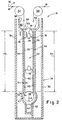
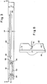
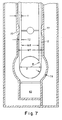
- A photographic processor for processing a photosensitive material, characterized in that:at least one processing channel (30) contains a processing solution through which the photosensitive material (12) passes for processing, said channel (30) having a substantially constant thickness T, at least one slot nozzle (76) is provided for directing processing solution against the photosensitive material (12) passing through said processing channel (30), said channel (30) being shaped such that the nozzle (76) is disposed a distance less than T from the opposing side wall (38) of the channel (30) such that the processing solution impinges against the photosensitive material (12).
- A photographic processor for processing photosensitive material, characterized in that the processor includes at least one processing section (18,20,22,24), said processing section comprising a tank (34) which forms a generally U-shaped chamber (40) and a rack (42) for placement in said chamber (40) and forming a narrow processing channel (44) having a thickness T between said rack (42) and said tank (34) for containing the processing solution, at least one nozzle (76) is provided for directing processing solution against the photographic material (12) passing through said processing channel (34), said nozzle (76) being positioned such that it is disposed from the opposing wall (38) of the channel a distance TZ no greater than 5.5mm.
- A processor according to claim 1 characterized in that the nozzle (76) is spaced from the opposing wall (38) of the channel (30) a distance TZ not greater than 5.5mm.
- A processor according to claim 1 characterized in that said nozzle (76) extends outward from the wall in which it is disposed.
- A processor according to claim 1 characterized in that the area of the wall (38) opposite said nozzle (76) extends into the processing channel (30).
- A processor according to claim 1 characterized in that both walls of the processing channel adjacent the nozzle (76) extend to the processing channel (30).
- A processor according to claim 4 characterized in that a recessed area is provided opposite said nozzle (76).
- A photograhic processor according to claim 2, characterized in that a belt (50) is provided for transporting the photosensitive material (12) through the processing channel (44).
- A processor according to claim 2, characterized in that said at least one slot nozzle (76) is provided in said rack (42).
Applications Claiming Priority (2)
| Application Number | Priority Date | Filing Date | Title |
|---|---|---|---|
| US799162 | 1985-11-18 | ||
| US08/799,162 US5761564A (en) | 1997-02-14 | 1997-02-14 | Photographic processing apparatus |
Publications (1)
| Publication Number | Publication Date |
|---|---|
| EP0859280A1 true EP0859280A1 (en) | 1998-08-19 |
Family
ID=25175188
Family Applications (1)
| Application Number | Title | Priority Date | Filing Date |
|---|---|---|---|
| EP98200302A Withdrawn EP0859280A1 (en) | 1997-02-14 | 1998-02-02 | Photographic processing apparatus |
Country Status (3)
| Country | Link |
|---|---|
| US (1) | US5761564A (en) |
| EP (1) | EP0859280A1 (en) |
| JP (1) | JPH10228087A (en) |
Families Citing this family (3)
| Publication number | Priority date | Publication date | Assignee | Title |
|---|---|---|---|---|
| US6739770B2 (en) | 2002-09-20 | 2004-05-25 | Eastman Kodak Company | Photographic processor having an exposure section with an inclined media path |
| US10642833B2 (en) | 2015-08-11 | 2020-05-05 | Sybase, Inc. | Accelerating database queries using composite union enumeration |
| US10467228B2 (en) | 2015-08-11 | 2019-11-05 | Sybase, Inc. | Accelerating database queries using equivalence union enumeration |
Citations (3)
| Publication number | Priority date | Publication date | Assignee | Title |
|---|---|---|---|---|
| WO1992009932A1 (en) * | 1990-11-24 | 1992-06-11 | Kodak Limited | Photographic processing apparatus |
| EP0590686A1 (en) * | 1992-10-02 | 1994-04-06 | Eastman Kodak Company | Apparatus for processing photosensitive material |
| US5387499A (en) * | 1990-02-14 | 1995-02-07 | Eastman Kodak Company | Method and apparatus for photographic processing |
Family Cites Families (8)
| Publication number | Priority date | Publication date | Assignee | Title |
|---|---|---|---|---|
| US2770179A (en) * | 1950-03-18 | 1956-11-13 | Pako Corp | Apparatus for processing strips of light-sensitive material |
| US2861508A (en) * | 1956-12-10 | 1958-11-25 | Unicorn Engineering Corp | Processing machine for sensitized paper and the like |
| NL151192B (en) * | 1965-10-06 | 1976-10-15 | Hoechst Ag | DEVICE FOR DEVELOPING LATENT, ELECTROSTATIC IMAGES. |
| US4044964A (en) * | 1976-09-07 | 1977-08-30 | Pako Corporation | Roll holder for photographic processors |
| US4775873A (en) * | 1988-02-05 | 1988-10-04 | Eastman Kodak Company | Photographic film processor rack and tank assembly |
| GB9012860D0 (en) * | 1990-06-08 | 1990-08-01 | Kodak Ltd | Photographic processing tank |
| US5452043A (en) * | 1993-02-19 | 1995-09-19 | Eastman Kodak Company | Rack and a tank for a photographic low volume thin tank insert for a rack and a tank photographic processing apparatus |
| US5508776A (en) * | 1995-05-10 | 1996-04-16 | Eastman Kodak Company | Apparatus for processing photosensitive material |
-
1997
- 1997-02-14 US US08/799,162 patent/US5761564A/en not_active Expired - Fee Related
-
1998
- 1998-02-02 EP EP98200302A patent/EP0859280A1/en not_active Withdrawn
- 1998-02-13 JP JP10031187A patent/JPH10228087A/en active Pending
Patent Citations (3)
| Publication number | Priority date | Publication date | Assignee | Title |
|---|---|---|---|---|
| US5387499A (en) * | 1990-02-14 | 1995-02-07 | Eastman Kodak Company | Method and apparatus for photographic processing |
| WO1992009932A1 (en) * | 1990-11-24 | 1992-06-11 | Kodak Limited | Photographic processing apparatus |
| EP0590686A1 (en) * | 1992-10-02 | 1994-04-06 | Eastman Kodak Company | Apparatus for processing photosensitive material |
Also Published As
| Publication number | Publication date |
|---|---|
| US5761564A (en) | 1998-06-02 |
| JPH10228087A (en) | 1998-08-25 |
Similar Documents
| Publication | Publication Date | Title |
|---|---|---|
| CA2108053A1 (en) | Apparatus for processing photosensitive material | |
| JP5005353B2 (en) | NOZZLE ARRAY FOR APPARATUS TREATMENT WITH TREATMENT | |
| EP0623841B1 (en) | Automatic processors | |
| US4065042A (en) | Web transporting apparatus | |
| US5761564A (en) | Photographic processing apparatus | |
| US5835812A (en) | Photographic processing apparatus | |
| US5323202A (en) | Photographic processing apparatus | |
| EP0703496B1 (en) | A rack and a tank for a photographic processing apparatus | |
| US5903795A (en) | Photographic processor | |
| JPS6037219B2 (en) | Liquid flow delivery device for textile products in liquid flow type textile product processing equipment | |
| CA1062299A (en) | Web transport apparatus | |
| EP0623847B1 (en) | Counter cross flow for automatic processors | |
| US5412447A (en) | Photographic processing apparatus | |
| US5822645A (en) | Photographic processor | |
| US6076980A (en) | Photographic processor having scrubbing rollers | |
| EP0603952B1 (en) | Photographic processing apparatus having a continuous transport belt with transverse slots | |
| EP0872766A1 (en) | Photographic processor | |
| US6062747A (en) | Clip | |
| JPH07175224A (en) | Substrate surface treating device | |
| US5920742A (en) | Nozzle assembly and a processing tank and method for processing photosensitive material using said nozzle assembly | |
| JP2694450B2 (en) | Equipment for processing silver halide photographic light-sensitive materials | |
| US5768651A (en) | Photographic processing apparatus | |
| JPH09230563A (en) | Photograph processor | |
| US6213656B1 (en) | Photographic processing apparatus having improved light-lock feature | |
| EP0909984B1 (en) | Processing photographic material |
Legal Events
| Date | Code | Title | Description |
|---|---|---|---|
| PUAI | Public reference made under article 153(3) epc to a published international application that has entered the european phase |
Free format text: ORIGINAL CODE: 0009012 |
|
| AK | Designated contracting states |
Kind code of ref document: A1 Designated state(s): CH DE GB IT LI |
|
| AX | Request for extension of the european patent |
Free format text: AL;LT;LV;MK;RO;SI |
|
| 17P | Request for examination filed |
Effective date: 19990129 |
|
| AKX | Designation fees paid |
Free format text: CH DE GB IT LI |
|
| RBV | Designated contracting states (corrected) |
Designated state(s): CH DE GB IT LI |
|
| 17Q | First examination report despatched |
Effective date: 20030613 |
|
| GRAP | Despatch of communication of intention to grant a patent |
Free format text: ORIGINAL CODE: EPIDOSNIGR1 |
|
| STAA | Information on the status of an ep patent application or granted ep patent |
Free format text: STATUS: THE APPLICATION IS DEEMED TO BE WITHDRAWN |
|
| 18D | Application deemed to be withdrawn |
Effective date: 20040916 |