BACKGROUND OF THE INVENTION
Field of the Invention:
The present invention relate to a surface
planarization apparatus for polishing a work in its pressed
state by a rotating surface plate and also to a work
measuring method.
Description of the Related Art:
Conventionally, a chemical and mechanical polishing
(hereinafter simply referred to as CMP) apparatus has been
known as such a kind of surface planarization apparatus.
Figure 13 shows in cross section an example of a CMP
apparatus. In Figure 13, a reference symbol 100 designates
a surface plate which is formed of a disk member with a
polishing pad 101 made of urethane being adhered to an upper
surface thereof. The surface plate 100 is mounted on an
upper surface of a rotation member or rotor 110 which in turn
is rotatably mounted on a central shaft 111 through a bearing
112. By energizing a drive means 130 such as a motor to
rotate the rotor 110, the surface plate 100 is caused to
rotate together with the rotor 110.
With this CMP apparatus, a work 200 disposed on the
surface plate 100 is urged or pressed against the surface
plate 100 by means of a carrier 210 so that it is driven to
rotate so as to be planarized or polished by the surface
plate 100 while a polishing medium such as a polishing liquid
is supplied thereto.
Specifically, the work 200 is pressed against the
surface plate 100 through a packing pad 211 to a lower
surface of which the carrier 210 is adhered. In this state,
the surface plate 100 and the carrier 210 are caused to
rotate in the right-hand or clockwise rotational direction at
the same rotation speed. At this time, the carrier 210 is
oscillated in a radial direction of the surface plate 100, as
shown by an arrow A.
Furthermore, the CMP apparatus is provided with a
laser sensor 300 for measuring the state of planarization or
polishing of the work 200.
Specifically, a small-diameter hole 120 is formed through the
polishing pad 101, the surface plate 100 and the rotor 110
with the laser sensor 300 being disposed under the hole
120.
With this arrangement, when the hole 120 comes right
above the laser sensor 300 during rotation of the surface
plate 100, a laser beam is issued from the laser sensor 300
toward the hole 120 to thereby measure the polishing state of
the work 200 over the hole 120.
However, the rotating surface plate of the
above-mentioned polishing apparatus has involved the
following problems.
During continued use of the polishing pad 101, the central
portion of the polishing pad 101 is worn out greater than the
inner and peripheral portions thereof.
That is, the polishing pad 101 has been frequently
subjected to a localized or non-uniform wear, and the
operation of the CMP apparatus has to be stopped every time
such a localized wear takes place, so that the polishing pad
101 is dressed, cutting down the inner and outer peripheral
portions up to the thickness of the central portion to
thereby level the entire surface of the pad. Otherwise, the
polishing pad 101 thus locally worn has to be replaced with
a new one. As a consequence, it is necessary to stop the CMP
apparatus for a long period of time, and hence the operating
rate of the apparatus is very bad.
Moreover, since when the rotating hole 120 comes
right above the laser sensor 300, it is necessary to operate
the laser sensor 300, the control of timing is very
difficult. Especially, since the work 200 is swung or
oscillated in a radial direction of the surface plate 100,
the oscillating movement of the carrier 210 need be
controlled to locate the central and peripheral portions of
the work 200 just above the hole 120 when the hole 120 comes
right above the laser sensor 300. Thus, such a control is
very difficult. As a consequence, the polishing state
of the work 200 can not be measured accurately.
Furthermore, the laser measurement has sometimes been
disabled or obstructed due to the polishing liquid collected
in the small hole 120. In addition, measurements are limited
to only the central portion and a part of the peripheral
portion of the work 200.
The present invention is intended to solve the
above-described various problems based on the following
consideration.
The inventors has noted a difference between the
length of sliding contact of the polishing pad 101 with the
work 200 when the work 200 is located at an outermost
peripheral portion of the polishing pad 101 and the length of
sliding contact thereof when the work 101 is located at an
innermost peripheral portion of the polishing pad 101.
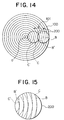
Figure 14 is a schematic plan view showing an
oscillating state of the work 200. Figure 15 is a comparison
chart in which sliding contact lines in Figure 14 are
superposed for the purpose of comparison.
When the surface plate 100 is located at the
outermost peripheral portion of the polishing pad 101 due to
a swinging or oscillating motion thereof in the direction of
arrow A as shown in Figure 14, a sliding contact line B
indicated at an alternate long and short dash line is taken,
whereas when the surface plate 100 is located at the
innermost peripheral portion of the polishing pad 101, a
sliding contact line C indicated at a short dashes line is
taken.
The length of the sliding contact line B increases
from the left-hand end of the work 200 to the central portion
thereof and decreases from the central portion toward the
right-hand end of the work 200. The length of the sliding
contact line C changes similarly, too.
However, as shown in Figure 15, the lengths of the
sliding contact lines B and C of the corresponding portions
of the work 200 vary according to the position of the work
200. For instance, when a comparison is made between a
leftmost sliding contact line B' when the work 200 is at an
outermost peripheral position and a sliding contact line C'
when the work 200 is at an innermost peripheral position, the
sliding contact line C' is longer than the sliding contact
line B'.
In order to analyze this phenomenon, the inventors
took the length of a sliding contact line as the
corresponding time of sliding contact, and considered the
sliding contact time at each position of the work 200.
Figure 16 schematically illustrates in a plan view
the position of oscillation or swing of the work 200, and
Figure 17 is a diagram illustrating the sliding contact time
in which the left-hand ordinate axis indicates the sliding
contact time at each position and the right-hand axis
ordinate indicates the value of time at which the sliding
contact times of respective positions are superposed one over
another.
First of all, when a work 200-1 is disposed at a
location P1 in Figure 16 (i.e., 162 mm apart from the center
O of the polishing pad 101), the sliding contact time of the
polishing pad 101 during which it contacts the work 200-1
takes a curve S1.
That is, the sliding contact time is 0 seconds at the
opposite ends of the work 200-1, and it takes a maximum value
of about 0.45 seconds substantially at the center of the work
200-1. Subsequently, when another work 200-2 is disposed at
a location P2 which is 171 mm apart from the center O of the
polishing pad 101, there is obtained a curve S2 having a
maximum value of 0.42 seconds.
In this manner, when works 200-3 through 200-6 were
disposed at locations P3 through P6 which are apart from the
center O of the polishing pad 101 by distances of 180 mm, 189
mm, 198 mm, 207 mm, 216 mm, and 225 mm, respectively, the
corresponding sliding contact times take curves S3 through
S6.
As can be seen from these curves S1 through S6, the
greater the distance of the work 200 from the center O of the
polishing pad 101 (i.e., as the work 200 moves from the
center O of the polishing pad 101 toward the outer periphery
thereof), the maximum value and the curvature of the sliding
contact time of each curve decreases.
Accordingly, as shown in Figure 16, when the work 200
(200-1 through 200-6) is swung or oscillated within the range
of a distance L, the time during which the work 200 is in
sliding contact with the polishing pad 101 becomes equal to
the time in which the curves S1 through S6 are superposed one
over another. Superposition of the curves S1 through S6
provides a curve T having a maximum value of about 3 seconds.
The curve T takes the shape of an arc which is gently sloping
at the central portion thereof designated at a range M, and
falls at the inner peripheral portion designated at a range
R and the outer peripheral portion designated at a range N.
Therefore, the polishing pad 101 is worn out violently in the
range M, and lesser in the ranges R and N. As a result, the
polishing pad 101 is worn out in the shape of an inverted
curve T, resulting in a localized wear, as shown in Figure
18.
In order to cope with such a localized wear, it is
considered to use a polishing pad having a lesser or finer
width or another one in the shape of a line ring.
Specifically, as shown in Figure 17, the curve T is
substantially horizontal in a limited range Δ in the vicinity
of the top of the curve T, so there will be caused no
localized wear. Therefore, if a polishing pad 101 in the
shape of a line ring and having a width of Δ while passing
through the top position of the curve T is driven to rotate
with the work 200 being caused to rotate and oscillate on the
line-ring-shaped polishing pad 101, an ideal polishing can be
achieved without generating any localized wear on the
polishing pad 101. However, when the polishing pad 101 is
formed into the line shape in this manner, the area of
contact thereof with the work 200 becomes small, thus
decreasing the polishing rate.
Another measure to cope with the above problem is
that the radius of the polishing pad 101 is made twice or
more the diameter of work 200, so that the surface of the
polishing pad 101 which is in sliding contact with the work
200 is always changed during swinging or oscillating motion
of the work 200.
However, it is not desirable in these days to provide
such a large-sized CMP apparatus particular in view of the
fact that miniaturization of a CMP apparatus is demanded.
SUMMARY OF THE INVENTION
Thus, the present invention is intended to provide a
novel and improved surface planarization apparatus and a work
measuring method in which a work can be processed or
planarized without reducing a processing or planarization
rate and an operating rate of the apparatus, and which is
capable of decreasing the overall size of the apparatus as
well as measuring the state of processing or planarization of
the work at a high degree of accuracy.
According to one aspect of the present invention,
there is provided a surface planarization apparatus
comprising: a rotatable surface plate; and a pressure member
adapted to oscillate a work in a radial direction of the
surface plate while urging the work against the surface
plate, wherein the surface plate is divided into an inner
surface plate member, an intermediate surface plate member
and an outer surface plate member which are all disposed in
a concentric relation with respect to each other and
rotatable independently of each other, the intermediate
surface plate member being disposed between the inner and
outer surface plate members.
With the above arrangement, by rotating the surface
plate and oscillating the work while pressing it against the
surface plate by means of the pressure member, the work is
processed or planarized by the rotating surface plate. After
repeated processing of a lot of works, the intermediate
surface plate member is worn out mush greater than the inner
and outer surface plate members, with the result that the
thickness of the intermediate surface plate member reduces
below a predetermined value faster or earlier than the inner
and outer surface plate members do. In this case, only the
intermediate surface plate member thus worn is detached and
replaced with a new one.
In a preferred form of the first aspect of the
invention, the umber of revolutions per unit time of each of
the intermediate surface plate member and the inner and
outer surface plate members is set such a manner that a
relative speed between the work and the at least one
intermediate surface plate member, a relative speed between
the work and the inner surface plate member, and a relative
speed between the work and the outer surface plate member are
all made equal to each other.
With the above arrangement, the speeds of processing
(e.g., polishing) of the work by means of the intermediate
surface plate member and the inner and outer surface plate
members are made substantially equal to each other.
In another preferred form of the first aspect of the
invention, the inner and outer surface plate members are made
to rotate in the same rotational direction and at the same
speed as those of the work.
Thus, the inner and outer surface plate members are
made stationary relative to the work, so that the
intermediate surface plate member alone contributes to the
processing or planarization of the work.
In a further preferred form of the first aspect of
the invention, the widths of the inner and outer surface
plate members and the intermediate surface plate member are
substantially the same with respect to each other.
Thus, the width of the intermediate surface plate
member is large, i.e., about one third of the width of the
entire surface plate, resulting in an increased area of
contact between the intermediate surface plate member and the
work, which makes the most contribution to the planarization
of the work.
In a further preferred form of the first aspect of
the invention, a pad is provided on a surface of each of the
inner and outer surface plate members and the intermediate
surface plate member.
Thus, by rotating the surface plate and oscillating
the work while pressing it against the surface plate by means
of the pressure member, the work is planarized or polished by
means of the pad on the surface of the surface plate.
In a further preferred form of the first aspect of
the invention, the pad of the intermediate surface plate
member is formed of a hard material, and the pads of the
inner and outer surface plate members are formed of a soft
material.
Thus, the work can be planarized or flattened by
means of the hard pad and at the same time made uniform by
means of the soft pads.
In a further preferred form of the first aspect of
the invention, the intermediate surface plate member
comprises a plurality of divided surface plate sections
disposed in a concentric relation with each other.
In a further preferred form of the first aspect of
the invention, a plurality of pads formed of a hard material
are each secured to a surface of each of the divided surface
plate sections.
According to another aspect of the invention, there
is provided a work measuring method adapted to be applied to
a surface planarization apparatus which comprises a rotatable
surface plate and a pressure member for oscillating a work
while urging it against the surface plate, the surface plate
comprising a plurality of divided surface plate members
concentrically disposed and being rotatable independently of
each other, the method comprising the steps of: disposing
measuring means in a space between the divided surface plate
members at a location through which the work passes in a
contactless relation with respect to the divided surface
plate members; and measuring the state of planarization of
the work which passes through the space by use of the
measuring means.
Thus, the measuring means, which is disposed in the
space between the divided surface plate members, permits
measurements to be conducted at all times without being
influences by the rotation of the divided surface plate
members.
In a preferred form of the second aspect of the
invention, the work measuring method further comprises the
steps of: oscillating the work in a radial direction of the
surface plate while rotating it; disposing a first sensor at
a first location through which a central portion of the work
passes; measuring the state of planarization of the work near
a central portion thereof by means of the first sensor;
disposing a second sensor in the space at a second location
through which a peripheral portion of the work passes; and
measuring the state of planarization of the work near the
peripheral portion thereof by means of the second sensor.
With the above steps, substantially the central
portion of the rotating work is measured by the first sensor
and at the same time the peripheral portion of the work is
measured by the second sensor, so that the state of
processing (e.g., polishing, planarization, uniformity, etc.)
of the almost entire surface of the work can be measured by
means of the first and second sensors.
In another preferred form of the second aspect of the
invention, the work measuring method further comprises the
steps of: oscillating the work in a direction substantially
perpendicular to a radial direction of the surface plate
while rotating the same; disposing a single sensor in the
space at a location through which a central portion of the
work passes; and measuring the state of planarization of the
work over a range from the central portion to a peripheral
portion thereof by means of the single sensor.
With the above steps, measurements are effected from
the center of the work to the peripheral portion thereof, so
the state of processing of the almost entire surface of the
work can be measured by use of the single sensor.
The above and other objects, features and advantages
of the present invention will more readily apparent to those
skilled in the art from the following detailed description of
the invention taken in conjunction with the accompanying
drawings.
BRIEF DESCRIPTION OF THE DRAWINGS
Figure 1 is a cross section showing a polishing
apparatus according to a first embodiment of the present
invention.
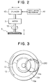
Figure is a block diagram showing a drive mechanism
for a carrier.
Figure 3 is a plan view showing the right-hand or
clockwise rotation of each of surface plate members.
Figure 4 is a cross section showing the detached
state of an intermediate surface plate member.
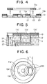
Figure 5 is a cross section showing the essential
parts of a CMP apparatus according to a second embodiment of
the present invention.
Figure 6 is a plan view showing the swinging or oscillating
state of a work.
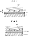
Figure 7 is a cross section showing a flattening or
planarization operation by means of a hard polishing pad.
Figure 8 is a cross section showing a uniform or
non-localized processing by a soft polishing pad.
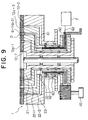
Figure 9 is a cross section of a CMP apparatus
according to a third embodiment of the present invention.
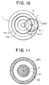
Figure 10 is a plan view showing the arrangement of
laser sensors.
Figure 11 is a plan view showing measurement areas of
the laser sensors
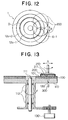
Figure 12 is a plan view showing a work measuring
method according to a fourth embodiment of the present
invention.
Figure 13 is a cross section showing a known CMP
apparatus.
Figure 14 is a schematic plan view showing the
swinging or oscillating state of a work.
Figure 15 is a comparison chart where sliding contact
lines in Figure 14 are superposed.
Figure 16 is a schematic plan view showing varying
positions of the work during its swinging or oscillating
movement.
Figure 17 is a diagram showing the time of sliding
contact, in which the left-hand ordinate axis indicates the
sliding contact time at respective positions of oscillation,
and the right-hand ordinate axis indicates the time value of
the sliding contact time superimposed at respective positions
of oscillation.
Figure 18 is a cross section showing the state of
localized wear of one polishing pad.
DESCRIPTION OF THE PREFERRED EMBODIMENTS
In the following, preferred embodiments of the
present invention will be described while referring to the
accompanying drawings.
(The First Embodiment)
Figure 1 shows in cross section a surface
planarization apparatus in the form of a polishing apparatus
according to a first embodiment of the present invention.
The polishing apparatus is a CMP apparatus which has
a surface plate 1 and a pressure member in the form of a
carrier 5. The surface plate 1 comprises three divided
surface plate members including an inner surface plate member
11, an intermediate surface plate member 12, and an outer
surface plate member 13, which are mounted on upper surfaces
of similarly divided corresponding rotating members or rotors
21, 22, 23, respectively.
Specifically, the rotor 21 is rotatably mounted
through a bearing 31 outside of the central shaft 2. The
rotors 22, 23 are rotatably sequentially mounted through
bearings 32. 33 outside of the rotor 21.
These rotors 21, 22, 23 have toothed portions 21a, 22a, 23a
formed on their lower portions, respectively. The toothed
portions 21a, 22a, 23a are in meshing engagement with gear
wheels 41a, 42a, 43a which are provided on rotation shafts of
drive members 41, 42, 43, respectively. By actuating the
drive members 41-43, the rotors 21-23 is driven to rotate
around the central shaft 2. The rotors 21-23 have upper
portions of substantially the same width and each being in
the shape of a ring.
The inner surface plate member 11, the intermediate
surface plate member 12, and the outer surface plate member
13 are mounted detachably to the top faces of the upper
portions of the rotors 21-23. The inner surface plate member
11 is formed of a metallic ring of the same width as that of
the upper portion of the rotor 21. A pad in the form of a
polishing pad 11a is attached or adhered to a surface of the
inner surface plate member 11.
Similarly, the intermediate surface plate member 12
and the outer surface plate member 13 are formed of metallic
rings of the same widths as those of the upper portions of
the rotors 22, 23, respectively. Also, pads in the form of
polishing pads 12a, 13a are attached or adhered to surfaces
of the intermediate surface plate member 12 and the outer
surface plate member 13, respectively.
That is, the inner surface plate member 11, the
intermediate surface plate member 12 and the outer surface
plate member 13 having the polishing pads 11a-13a have
substantially the same widths, and are disposed
concentrically around the central shaft 2 so that they are
driven to rotate independently of each other by means of the
drive members 41-43.
The widths of the inner surface plate member 11, the
intermediate surface plate member 12 and the outer surface
plate member 13 are described below.
As shown in the curve T in Figure 17, the part within
the range M of the polishing pad is worn out most when the
work is oscillated. Moreover, the curvature of the curve T
in the part within the range M is very small, and hence the
part or range M is substantially flat. As a consequence, the
phenomenon of localized wear is hardly caused in the part
within the range M. For this reason, the width of the
intermediate surface plate member 12 is set to substantially
the same size as the range M, and the widths of the inner
surface plate member 11 and the outer surface plate member 13
are each set to substantially the same width of the
intermediate surface plate member 12.
On the other hand, in Figure 1, the carrier 5 is
formed on a first or lower surface thereof with a circular
work holding recess or opening 50 in which a packing pad 51
is received, the packing pad 51 being secured or adhered to
the lower surface of the carrier 5. A rod 52 is vertically
mounted at its one or lower end on a second or upper surface
of the carrier 5. The rod 52 is connected at its other or
upper end with a motor 3, as shown in Figure 2, so that the
carrier 5 is driven to rotate on its own axis of rotation
under the drive of the motor 3 through the rod 52. The motor
3 is operably connected with a cylinder 40 so that the
carrier 5 can be caused to move vertically by means of the
cylinder 40 through the intermediary of the motor 3. The
cylinder 40 is operably connected with an oscillating
mechanism 41 so that the whole of the cylinder 40, the motor
3 and the carrier 5 can be oscillated laterally or to the
right and left of Figure 2 under the action of the
oscillating mechanism 41.
Next, the operation of the polishing apparatus
according to this embodiment will be described below.
As shown in Figure 1, the carrier 5 holding the work
200 is driven to rotate on its own axis by means of the motor
3 (see Figure 2) and at the same time to move in a downward
direction under the action of the cylinder 40. In this
state, when the oscillating mechanism 41 is actuated to
oscillate or swing the carrier 5 in a radial direction of the
surface plate 1, i.e., to the right and left of Figure 1, the
work 200 is caused to oscillate or swing on the surface plate
1 while being pressed thereagainst.
Simultaneous with this operation, the Inner surface
plate member 11, the intermediate surface plate member 12 and
the outer surface plate member 13 of the surface plate 1 are
driven to rotate by means of the drive members 41-43 while an
unillustrated polishing medium such as a polishing liquid is
being supplied thereto.
Specifically, the intermediate surface plate member
12 is driven to rotate by the drive member 42 in the same
rotational direction as the direction of self rotation of the
work 200, as shown in Figure 3. At this time, the number of
revolutions per unit time or rotating speed of the
intermediate surface plate member 12 and that of the work 200
are set to the same value.
Furthermore, the inner surface plate member 11 is
driven to rotate by the oscillating mechanism 41 in a
direction opposite the direction of self rotation of the work
200. At this time, the number of revolutions per unit time
or rotating speed of the inner surface plate member 11 is set
in such a manner as to minimize the relative speed of that
part thereof which contacts the work 200 with respect to the
rotating speed of the latter.
In addition, the outer surface plate member 13 is
rotated by the drive member 43 in the same direction as the
direction of self rotation of the work 200. In this regard,
the number of revolutions per unit time of the outer surface
plate member 13 is appropriately set so as to minimize the
relative speed of the part thereof contacting the work 200
with respect to the rotating speed of the latter.
Specifically, the direction of rotation and the
number of revolutions per unit time of each of the inner
surface plate member 11 and the outer surface plate member 13
are set in such a manner that the polishing pads 11a, 13a on
the inner surface plate member 11 and the outer surface plate
member 13 are made substantially stationary relative to the
work 200.
Also, the rotational direction and the number of
revolutions per unit time of the intermediate surface plate
member 12 is set such that the polishing pad 12a of the
intermediate surface plate member 12 can make the most
contribution to the polishing of the work 200. Thus, the
work 200, which is caused to oscillate while rotating on its
own axis, is polished by the rotating surface plate 1. At
this time, the inner and outer surface plate members 11, 13
are substantially stationary relative to the work 200, and
hence they are in a state of merely supporting the work 200
on its opposite sides. As a consequence, the polishing pads
11a, 13a are not worn out to any substantial extent.
The entire lower surface of the work 200, which is
made into contact with the polishing pad 12a during self
rotation and oscillating motion of the work 200, is polished
by the polishing pad 12a. Therefore, the polishing pad 12a
might be worn out, and a localized wear might be caused to
the polishing pad 12a. If localized wear is generated, the
work 200 can not uniformly contact the polishing pad 12a, and
there will be irregularities or localization in the polishing
of the work 200.
In this case, however, as described above, the width
of the polishing pad 12a is set substantially equal to the
range M as shown in Figure 17 so that the polishing pad 12a
is worn out substantially flatly, thus hardly causing any
localized wear on the polishing pad 12a. Therefore, there
will be substantially no or little localization or
irregularities in the polishing of the work 200, as a result
of which the work 200 can be flattened or planarized at a
high polishing rate.
In cases where the polishing pad 12a has been worn
out more than a predetermined value (e.g., 60% of the
original thickness) after repeated polishing operations, the
heavily worn intermediate surface plate member 12 alone is
detached from the rotor 22, as shown in Figure 4, and
replaced with a new one to which a new polishing pad is
adhered.
As described above, according to the polishing
apparatus of this embodiment, the polishing operation can be
continued or resumed at once with a limited time loss only by
exchanging the used intermediate surface plate member 12
having the worn-out polishing pad 12a alone, so down time of
the apparatus can be shortened, thus improving the operating
rate of the apparatus.
Furthermore, since the polishing pad 12a is uniformly
worn out, the operator has only to observe the surface
roughness thereof, and hence control of the polishing pad 12a
is easy.
In addition, the inner surface plate member 11 and
the outer surface plate member 13 are substantially in a
stationary state relative to the work 200, so they are hardly
worn out, thus prolonging the life time of the surface plate
1.
Moreover, in cases where the inner surface plate
member 11, the intermediate surface plate member 12 and the
outer surface plate member 13 have been worn out and have to
be replaced with new ones, these mutually divided surface
plate members can be detached and exchanged separately with
new ones without difficulty, That is, in the past, it was
necessary to detach and mount a single large-sized and
heavily-weighted surface plate 100, and hence an exchange of
the surface plate 100 was cumbersome and difficult.
However, by dividing the surface plate 1 into three
in this embodiment, the small-sized and light-weighted inner,
intermediate and outer surface plate members 11, 12, 13 can
be exchanged separately from each other, thus achieving a
speedy and easy exchange work with less trouble and
difficulty.
Furthermore, since the width of the intermediate
surface plate member 12 is set substantially equal to the
range M indicated in Figure 17, a great area of contact of
the polishing pad 12a with the work 200 is ensured, thus
resulting in an extremely high polishing rate.
Still further, in the above-mentioned known
technique, a large-sized surface plate having a radius twice
or more the diameter of the work is required for preventing
localized wear of the polishing pad while keeping a required
area of contact thereof with the work.
However, by employing the surface plate 1 of a
three-divided structure including the inner, intermediate and
outer surface plate members 11, 12, 13 as in the CMP
appparatus of this embodiment, it is possible to achieve
substantially the same results even with a limited swing or
oscillating distance of the work 200. As a result, the
surface plate 1 can be miniaturized.
Further, in the past, it was necessary to rotate the
large-sized surface plate of a heavy weight, and it was
difficult to achieve a high-speed rotation of the surface
plate, but with the CMP apparatus of this embodiment, the
surface plate 1 is divided into three, resulting a
substantially reduced weight of the intermediate surface
plate member 12 which is to be rotated.
Consequently, the polishing pad 12a can be made
substantially hard by rotating the intermediate surface plate
member 12, which contributes to the polishing, at high speed.
As a result, a highly accurate flattening or planarization of
the work 200 can be achieved.
(The Second Embodiment)
Figure 5 shows in cross section the essential parts
of a CMP apparatus according to a second embodiment of the
present invention.
In general, a work is not completely flat or planar.
For instance, a work such as a wafer generally includes
warpage and/or distortions which were caused by heating
during processing. Also, the work includes steps on an
irregular or ruggedness surface resulting from wiring
patterns formed thereon.
As a consequence, when polishing such a work, a
polishing pad requires flatness for reducing steps in the
regularities, and uniformity by which the polishing pad is
deformable so as to follow warpage and/or irregularities on
the surface of the work to polish a surface layer to a
constant thickness.
The CMP apparatus of this embodiment can satisfy the
above-mentioned requirements by the use of a single-layer
polishing pad. The hardness of the polishing pads to be
adhered to the inner surface plate member 11, the
intermediate surface plate member 12 and the outer surface
plate member 13 is varied.
Specifically, soft polishing pads 11a', 13a' in the
form of a SUBA-IV pad are attached or adhered to the inner
surface plate member 11 and the outer surface plate member
13, and a hard polishing pad 12a' in the form of an IC-1000
urethane pad is attached or adhered to the intermediate
surface plate member 12.
In the operation of this CMP apparatus, the
rotational directions of the inner surface plate member 11,
the intermediate surface plate member 12 and the outer
surface plate member 13 are the same as in the case of the
above-mentioned first embodiment, but the rotating speeds of
the inner surface plate member 11 and the outer surface plate
member 13 are different from those in the case of the
above-mentioned first embodiment.
That is, in the second embodiment, the rotating
speeds of the inner surface plate member 11 and the outer
surface plate member 13 are set in such a manner that the
relative speeds of the soft polishing pads 11a', 13a' with
respect to the work 200 are great enough to polish the work
200 by means of the soft polishing pads 11a', 13a'.
In addition, as shown in Figure 6, the carrier 5 is
controlled in such a manner that the swing or oscillating
distance L of the work 200 is greater than the width of the
hard polishing pad 12a'.
Thus, as indicated by the solid line in Figure 6, the
work 200 when existing on the hard polishing pad 12a'
polishes convex portions which are caused by the wiring
pattern 201 of the work 200, thereby reducing steps H, as
shown in Figure 7, so that the work 200 is flattened or
planarized by the hard polishing pad 12a'.
On the other hand, when the work 200 exists on the
soft polishing pads 11a', 13a', as shown by a short dashes
line and an alternate long and two short dashes line in
Figure 6, the soft polishing pads 11a', 13a' are deformed so
as to follow the ruggedness and/or warpage of the work 200,
thereby polishing the surface Of the work 200 in a uniform
manner; as shown in Figure 8. As a consequence, the surface
of the work 200 is made uniform by means of the soft
polishing pads 11a', 13a'.
In this manner, according to the CMP apparatus of the
second embodiment, the work 200 can be flattened or
planarized and made uniform by means of the single-layer
polishing pad comprising the soft polishing pads 11a', 13a'
and the hard polishing pad 12a'.
As a technique to achieve such flatness and
uniformity with a single CMP apparatus, it is generally known
that a soft polishing pad and a hard polishing pad are
disposed one over the other on a single surface plate so as
to flatten or planarize the surface of a work by means of the
hard polishing pad while following warpage and the like of
the work by means of the soft polishing pad.
With such a technique, however, two wide polishing
pads each corresponding in area to the single surface plate
are required, thus increasing the cost of parts.
In contrast to this, the CMP apparatus of this
embodiment only requires one polishing pad of a single layer,
so the cost of parts can be suppressed or reduced to a
substantial extent.
The construction and operation of this second
embodiment other than the above are similar to those of the
above-mentioned first embodiment, and hence a description
thereof is omitted.
(The Third Embodiment)
Figure 9 shows in cross section a CMP apparatus
according to a third embodiment of the present invention.
The CMP apparatus of this embodiment concretely achieves a
work measuring method of the present invention.
This CMP apparatus is different from those of the
above-mentioned first and second embodiments in the provision
of a measuring device for measuring the thickness of a work
through a space between surface plate members. The measuring
device comprises two laser sensors 6-1, 6-2 and a computing
unit 7. The laser sensors 6-1, 6-2 are disposed in an
annular space P defined between two concentrically disposed
intermediate surface plate sections 12-1, 12-2.
Specifically, a first intermediate rotor 22-1 is
rotatably mounted on an inner rotor 21 through a bearing
32-1. A hollow stationary member 60 is fixedly provided
outside the rotor 22-1. A second intermediate rotor 22-2 is
rotatably mounted on the stationary member 60 through a
bearing 32-2. These first and second intermediate rotors
22-1 and 22-2 are driven to integrally rotate by means of a
drive member 42.
The first and second intermediate surface plate
sections 12-1, 12-2 having polishing pads 12a-1, 12a-2,
respectively, are detachably mounted on the first and second
intermediate rotors 22-1, 22-2. The sum of the widths of the
polishing pads 12a-1, 12a-2 is set substantially equal to the
range M indicated in Figure 17.
The laser sensors 6-1, 6-2 are disposed in the
annular space D in such a manner as not to contact these
intermediate surface plate sections 12-1, 12-2. The laser
sensors 6-1, 6-2 are each attached to or held on an upper end
of a hard tubing 61 which is connected with an upper end of
the stationary member 60, the tubing 60 being disposed in and
extending through the space D between the first and second
intermediate rotors 22-1, 22-2.
Each of the laser sensors 6-1, 6-2 disposed in this
manner is a well-known device which irradiates a laser beam
to the work 200 so as to measure the thickness of the work
200, and outputs a signal indicative of the measurement value
to the computing unit 7.
A lead wire 62 extending from each laser sensor
6-1(6-2) is passed through the tubing 61 and the stationary
member 60, drawn out from a lower side of the stationary
member 60, and connected to the computing unit 7.
The two laser sensors 6-1, 6-2 are respectively
disposed at predetermined locations within the annular space
D. Specifically, the laser sensor 6-1 is disposed at a
location through which the central portion of the work 200
passes when it swings or oscillates in the direction of arrow
A (i.e., in a radial direction of the surface plate 1) while
rotating on its own axes, as shown in Figure 10. The laser
sensor 6-2 is disposed at a location through which a
peripheral portion of the work 200 passes.
On the other hand, the computing unit 7 is a
well-known device which can arithmetically operate or compute
the flatness and/or uniformity of the work 200 based on the
measured value of the thickness of the work 200 which is
indicated by the signals from the laser sensors 6-1, 6-2.
Next, the operation of the CMP apparatus of the third
embodiment will be described.
As shown in Figure 10, when the work 200 is swinging
or oscillating in the direction of arrow A while rotating on
its own axis, the laser sensor 6-1 measures the thickness of
the work 200 every time the work 200 passes right above the
laser sensor 6-1 and generates a corresponding signal to the
computing unit 7 which computes the thickness of that portion
of the work 200 which passes right above the laser sensor
6-1.
In this case, since the work 200 is repeatedly
oscillated while rotating on its own axis, the laser sensor
6-1 measures the thickness of a circular area S1 of the work
200 which is in the vicinity of the central point P of the
work 200 and has a diameter equal to the length or distance
of oscillation of the work 200, as illustrated in figure 11.
The computing unit 7 computes the thickness of the circular
area S1.
Furthermore, the laser sensor 6-2 measures a
peripheral portion of the work 200. Since the work 200 is
repeatedly swung or oscillated while rotating on its own
axis, the thickness of a ring -shaped or annular area S2 in
the peripheral portion of the work 200 is measured by the
laser sensor 6-2, as shown in Figure 11.
Therefore, in this embodiment, by making the length
or distance of the swinging or oscillating movement of the
work 200 great, and by bringing the position of the laser
sensor 6-2 close to the central point P of the work 200, it
is possible to measure the thickness of respective portions
of the work 200 substantially over the entire surface
thereof.
Moreover, uniformity of the lower surface of the work
200 can be determined from the measured value of the laser
sensor 6-1 subtracted by the measured value of the laser
sensor 6-2, and at the same time, the state of ruggedness or
irregularities of the polishing indicative of the condition
of processing can also be seen.
That is, when the balance or subtracted value is a
positive value, the lower surface of the work 200 is convex,
whereas when it is a negative value, the lower surface of the
work 200 is concave.
As can be seen from the foregoing, according to the
CMP apparatus of this embodiment, the operation timing of the
laser sensors 6-1, 6-2 need not be considered, so it is
possible to measure the flatness and uniformity of the work
200 at a high degree of accuracy through simple and easy
measurement control.
Further, since the space D is not a small hole but a
ring-shaped or annular space, it is possible to avoid a
situation that a polishing liquid collected in the space D
might preclude measurements of the laser sensors 6-1, 6-2.
Since the construction and operation of this third
embodiment other than the above are similar to those of the
above-mentioned first and second embodiments, a description
thereof is omitted.
(The Fourth Embodiment)
A fourth embodiment of the present invention relates
to a work measuring method which is practically carried out
by utilizing the CMP apparatus according to the
above-mentioned third embodiment.
Figure 12 shows in a plan view the work measuring
method according to the fourth embodiment of the present
invention. In this embodiment, the work 200 is oscillated in
a direction perpendicular to a radial direction of the
surface plate 1 as indicated by arrow B in Figure 12, i.e.,
in a tangential direction of the annular space D.
Specifically, the work 200 is oscillated such that
the central point P of the work 200 passes right above the
laser sensor 6-1, and the lower end of the peripheral portion
of the work 200, which is at an uppermost position in Figure
12 as indicated by a short dashes line, is located right
above the laser sensor 6-1, and the upper end of the
peripheral portion of the work 200, which is at a lowermost
position in Figure 12 as indicated by an alternate long and
two short dashes line, is located right above the laser
sensor 6-1.
With this arrangement, the laser sensor 6-1 measures
the thickness of the work 200 from its central point P to its
peripheral portion edge, so that the entire lower surface of
the work 200 is measured by use of only one laser sensor 6-1
when the work 200 is oscillated in the direction of arrow B
while rotating on its own axis.
The construction and operation of the fourth
embodiment are similar to those of the above-mentioned first
to third embodiments, and thus a description thereof is
omitted.
Here, it is to be noted that the present invention is
not limited to the above-mentioned embodiments, but various
changes or modifications can be made within the spirit and
scope of the invention as defined in the appended claims.
In the above-mentioned embodiments, the CMP apparatus
has been consistently described, but the present invention
can also be applied to other apparatuses.
For instance, in a one-side lapping apparatus which
can flatten or planarize a surface of a work by rotating it
while urging it against a lower surface plate by means of a
pressure member in the form of a head which is swung or
oscillated, dividing the lower surface plate into a plurality
of surface plate members can achieve substantially the same
results as with the CMP apparatus according to any one of the
above-mentioned embodiments.
Also, in a one-side polishing apparatus which can
perform a delicate polishing by means of a pressure member in
the form of a head and a lower surface plate having a
polishing pad adhered thereto, dividing the lower surface
plate and the polishing pad into a plurality of pieces can
achieve substantially the same results.
Furthermore, in the above-mentioned embodiments, the
widths of the inner surface plate member, the intermediate
surface plate member and the outer surface plate member are
set substantially equal to each other, but it is evident that
the widths of these members may be different from each other
as long as the width of the intermediate surface plate member
is substantially equal to or less than the range M indicated
in Figure 17.
Although in the above-mentioned second embodiment,
the soft polishing pads 11a', 13a' comprise SUBA-IV pads and
the hard polishing pad 12a' comprises a IC-1000 urethane pad,
the present invention is not limited to the use of these pads
but any other suitable pads can instead be employed.
Specifically, the soft polishing pads 11a', 13a' can
be formed of any suitable soft material which is able to
deform so as to follow warpage and the like of the work 200.
Also, the hard polishing pad 12a' can be formed of any
suitable hard material which is able to flatten or planarize
a surface of the work 200.
Moreover, the rotational direction and the rotating
speed of each of the inner surface plate member, the
intermediate surface plate member and the outer surface plate
member can optionally be determined according to the contents
of an operation or job required, and thus these are not
limited to what is disclosed in the above-mentioned
embodiments.
For instance, the number of revolutions per unit time
of each of the intermediate surface plate member, the inner
surface plate member and the outer surface plate member can
be set such that the relative speed between the work and the
intermediate surface plate member, the relative speed between
the work and the inner surface plate member and the relative
speed between the work and the outer surface plate member are
made equal to each other.
With such settings, the speeds or rates of polishing
or planarization of the work by means of the intermediate
surface plate member, the inner surface plate member and the
outer surface plate member can be made the same.
In addition, in the above-mentioned embodiments,
dividing the surface plate into three or four pieces has been
described by way of example, but the number of division is
arbitrary.
As described above in detail, the following
advantages will be obtained according to the present
invention.
The surface plate is divided into the inner surface
plate member, the outer surface plate member and the
intermediate surface plate member, so that when the surface
plate has been subjected to localized wear, the operation or
processing can be continued or resumed at once merely by
exchanging the intermediate surface plate member alone which
has been worn out violently. Thus, the down time of the
apparatus can be shorted, improving the operating ratio to a
considerable extent.
Furthermore, even when the entire surface plate is to
be exchanged, the divided surface plate members each of a
relatively light weight can be exchanged separately or
independently of each other, so the exchange work for the
surface plate can be done swiftly and easily.
By making the speeds or rates of processing or
planarization of the work by means of the respective surface
plate members equal to each other, a uniform processing or
planarization of the work can be carried out reliably in a
short time.
The inner surface plate member and the outer surface
plate member are made substantially stationary relative to
the work, so there will be substantially no wear of the inner
surface plate member and the outer surface plate member. As
a result, it is possible to accordingly prolong the useful
life of the surface plate.
Moreover, a large area of contact between the
intermediate surface plate member and the work can be
ensured, thus achieving a further improvement in the rate of
processing or planarization.
Since polishing pads are provided on the intermediate
surface plate member, the inner surface plate member and the
outer surface plate member, the apparatus of the present
invention can be used as various kinds of apparatuses such as
a CMP apparatus. In these apparatuses, too, it is possible
to improve the operating rate and the processing or
planarization rate, prolong the life time of the surface
plate, and reduce the whole size.
By use of the single-layer polishing pads comprising
soft polishing pads and a hard polishing pad, both
planarization and uniformity of the work can be achieved,
thus making it possible to reduce the cost of parts.
The state of processing or planarization of the work
can be measured at all times without being influenced by the
rotation of the surface plate, so that no consideration need
be given to the timing of rotation of the hole 120 and
irradiation of a laser beam as in the case of the known laser
sensor 300. Consequently, the control of measurements can be
simplified, and a highly accurate measurement of the work can
be made.
In one embodiment, the state of processing or
planarization of the almost entire surface of the work can be
measured by means of first and second sensors, so it is
possible to further improve the accurate in the measurements.
In another embodiment, the state of processing or
planarization of the almost entire surface of the work can be
measured by use of a single sensor, so it is possible to
decrease the cost of measuring equipment.