EP0860708A2 - Method and system for determining a position of a transceiver unit utilizing two-way ranging in a polystatic satellite configuration including a ground radar - Google Patents
Method and system for determining a position of a transceiver unit utilizing two-way ranging in a polystatic satellite configuration including a ground radar Download PDFInfo
- Publication number
- EP0860708A2 EP0860708A2 EP98103057A EP98103057A EP0860708A2 EP 0860708 A2 EP0860708 A2 EP 0860708A2 EP 98103057 A EP98103057 A EP 98103057A EP 98103057 A EP98103057 A EP 98103057A EP 0860708 A2 EP0860708 A2 EP 0860708A2
- Authority
- EP
- European Patent Office
- Prior art keywords
- ranging signal
- transceiver
- ranging
- transmitting
- communication
- Prior art date
- Legal status (The legal status is an assumption and is not a legal conclusion. Google has not performed a legal analysis and makes no representation as to the accuracy of the status listed.)
- Granted
Links
Images

Classifications
-
- G—PHYSICS
- G01—MEASURING; TESTING
- G01S—RADIO DIRECTION-FINDING; RADIO NAVIGATION; DETERMINING DISTANCE OR VELOCITY BY USE OF RADIO WAVES; LOCATING OR PRESENCE-DETECTING BY USE OF THE REFLECTION OR RERADIATION OF RADIO WAVES; ANALOGOUS ARRANGEMENTS USING OTHER WAVES
- G01S5/00—Position-fixing by co-ordinating two or more direction or position line determinations; Position-fixing by co-ordinating two or more distance determinations
- G01S5/0009—Transmission of position information to remote stations
- G01S5/0045—Transmission from base station to mobile station
- G01S5/0054—Transmission from base station to mobile station of actual mobile position, i.e. position calculation on base station
-
- G—PHYSICS
- G01—MEASURING; TESTING
- G01S—RADIO DIRECTION-FINDING; RADIO NAVIGATION; DETERMINING DISTANCE OR VELOCITY BY USE OF RADIO WAVES; LOCATING OR PRESENCE-DETECTING BY USE OF THE REFLECTION OR RERADIATION OF RADIO WAVES; ANALOGOUS ARRANGEMENTS USING OTHER WAVES
- G01S13/00—Systems using the reflection or reradiation of radio waves, e.g. radar systems; Analogous systems using reflection or reradiation of waves whose nature or wavelength is irrelevant or unspecified
- G01S13/003—Bistatic radar systems; Multistatic radar systems
-
- G—PHYSICS
- G01—MEASURING; TESTING
- G01S—RADIO DIRECTION-FINDING; RADIO NAVIGATION; DETERMINING DISTANCE OR VELOCITY BY USE OF RADIO WAVES; LOCATING OR PRESENCE-DETECTING BY USE OF THE REFLECTION OR RERADIATION OF RADIO WAVES; ANALOGOUS ARRANGEMENTS USING OTHER WAVES
- G01S13/00—Systems using the reflection or reradiation of radio waves, e.g. radar systems; Analogous systems using reflection or reradiation of waves whose nature or wavelength is irrelevant or unspecified
- G01S13/87—Combinations of radar systems, e.g. primary radar and secondary radar
- G01S13/878—Combination of several spaced transmitters or receivers of known location for determining the position of a transponder or a reflector
-
- G—PHYSICS
- G01—MEASURING; TESTING
- G01S—RADIO DIRECTION-FINDING; RADIO NAVIGATION; DETERMINING DISTANCE OR VELOCITY BY USE OF RADIO WAVES; LOCATING OR PRESENCE-DETECTING BY USE OF THE REFLECTION OR RERADIATION OF RADIO WAVES; ANALOGOUS ARRANGEMENTS USING OTHER WAVES
- G01S19/00—Satellite radio beacon positioning systems; Determining position, velocity or attitude using signals transmitted by such systems
- G01S19/01—Satellite radio beacon positioning systems transmitting time-stamped messages, e.g. GPS [Global Positioning System], GLONASS [Global Orbiting Navigation Satellite System] or GALILEO
- G01S19/03—Cooperating elements; Interaction or communication between different cooperating elements or between cooperating elements and receivers
- G01S19/09—Cooperating elements; Interaction or communication between different cooperating elements or between cooperating elements and receivers providing processing capability normally carried out by the receiver
-
- G—PHYSICS
- G01—MEASURING; TESTING
- G01S—RADIO DIRECTION-FINDING; RADIO NAVIGATION; DETERMINING DISTANCE OR VELOCITY BY USE OF RADIO WAVES; LOCATING OR PRESENCE-DETECTING BY USE OF THE REFLECTION OR RERADIATION OF RADIO WAVES; ANALOGOUS ARRANGEMENTS USING OTHER WAVES
- G01S19/00—Satellite radio beacon positioning systems; Determining position, velocity or attitude using signals transmitted by such systems
- G01S19/01—Satellite radio beacon positioning systems transmitting time-stamped messages, e.g. GPS [Global Positioning System], GLONASS [Global Orbiting Navigation Satellite System] or GALILEO
- G01S19/13—Receivers
- G01S19/14—Receivers specially adapted for specific applications
- G01S19/15—Aircraft landing systems
-
- G—PHYSICS
- G01—MEASURING; TESTING
- G01S—RADIO DIRECTION-FINDING; RADIO NAVIGATION; DETERMINING DISTANCE OR VELOCITY BY USE OF RADIO WAVES; LOCATING OR PRESENCE-DETECTING BY USE OF THE REFLECTION OR RERADIATION OF RADIO WAVES; ANALOGOUS ARRANGEMENTS USING OTHER WAVES
- G01S19/00—Satellite radio beacon positioning systems; Determining position, velocity or attitude using signals transmitted by such systems
- G01S19/01—Satellite radio beacon positioning systems transmitting time-stamped messages, e.g. GPS [Global Positioning System], GLONASS [Global Orbiting Navigation Satellite System] or GALILEO
- G01S19/13—Receivers
- G01S19/35—Constructional details or hardware or software details of the signal processing chain
- G01S19/36—Constructional details or hardware or software details of the signal processing chain relating to the receiver frond end
-
- G—PHYSICS
- G01—MEASURING; TESTING
- G01S—RADIO DIRECTION-FINDING; RADIO NAVIGATION; DETERMINING DISTANCE OR VELOCITY BY USE OF RADIO WAVES; LOCATING OR PRESENCE-DETECTING BY USE OF THE REFLECTION OR RERADIATION OF RADIO WAVES; ANALOGOUS ARRANGEMENTS USING OTHER WAVES
- G01S5/00—Position-fixing by co-ordinating two or more direction or position line determinations; Position-fixing by co-ordinating two or more distance determinations
- G01S5/02—Position-fixing by co-ordinating two or more direction or position line determinations; Position-fixing by co-ordinating two or more distance determinations using radio waves
- G01S5/14—Determining absolute distances from a plurality of spaced points of known location
-
- G—PHYSICS
- G01—MEASURING; TESTING
- G01S—RADIO DIRECTION-FINDING; RADIO NAVIGATION; DETERMINING DISTANCE OR VELOCITY BY USE OF RADIO WAVES; LOCATING OR PRESENCE-DETECTING BY USE OF THE REFLECTION OR RERADIATION OF RADIO WAVES; ANALOGOUS ARRANGEMENTS USING OTHER WAVES
- G01S13/00—Systems using the reflection or reradiation of radio waves, e.g. radar systems; Analogous systems using reflection or reradiation of waves whose nature or wavelength is irrelevant or unspecified
- G01S13/74—Systems using reradiation of radio waves, e.g. secondary radar systems; Analogous systems
Definitions
- This invention relates to methods and systems for determining a position of a transceiver unit, such as those employed on an aircraft, utilizing two-way ranging in a polystatic satellite configuration including a ground radar.
- GPS Global Positioning System
- WAAS Wide Area Augmentation System
- GLONASS Global Navigational System
- GPS Global Positioning System
- GLONASS Global Navigational System
- GPS satellites transmit continuous time and position information 24 hours a day to a GPS receiver, which listens to three or more satellites at once to determine the user's position.
- the GPS receiver calculates the distance between the user and each satellite, and then uses the distance measurements of at least three satellites to arrive at a position.
- a method for determining position of an object.
- the method includes the steps of transmitting a first ranging signal from a first known ground location to the object and transmitting a second ranging signal in response to the first ranging signal to the first known ground location.
- the method also includes the steps of transmitting a third ranging signal in response to the first ranging signal to a second known location and transmitting a fourth ranging signal in response to the third ranging signal to a third known location.
- the method further includes the step of determining a first delay corresponding to a time difference between transmission of the first ranging signal and receipt of the second ranging signal.
- the method also includes the step of determining a second delay corresponding to a time difference between transmission of the first ranging signal and receipt of the third ranging signal. Still further, the method includes the step of determining a third delay corresponding to a time difference between transmission of the first ranging signal and receipt of the fourth ranging signal. The method finally includes the step of determining the position of the object based on the first, second, and third known locations and the first, second and third delays.
- the system includes a ground transceiver at a first known ground location for providing a bidirectional communication path between the ground transceiver and the object wherein the ground transceiver transmits a first ranging signal to the object and the object transmits a second ranging signal to the ground transceiver in response to the first ranging signal.
- the system also includes a first communication transceiver at a second known location for providing a first unidirectional communication path between the first communication transceiver and the object wherein the first communication transceiver performs one of transmitting a third ranging signal to the object and receiving a third ranging signal from the object in response to the first ranging signal.
- the system further includes a second communication transceiver at a third known location for providing a second unidirectional communication path between the second communication transceiver and the object wherein the second communication transceiver performs one of transmitting a fourth ranging signal to the object and receiving a fourth ranging signal from the object in response to the first ranging signal.
- the system includes a signal processor for determining a first path length corresponding to a first time length of the bidirectional communication path, determining a second path length corresponding to a second time length of the first unidirectional communication path, determining a third path length corresponding to a third time length of the second unidirectional communication path, and determining the position of the object based on the first, second, and third known locations and the first, second, and third path lengths.
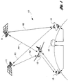
- a communication system 10 with a typical geometry for practicing the present invention is diagrammatically illustrated.
- the present invention is particularly suited for determining the position of an aircraft during Category I landings, as described with reference to the preferred embodiment.
- the present invention is also suitable for tracking other objects, such as a surface ground vehicle.
- Aircraft 12 communicates with at least one traffic controller station 16 via a ground radar 13 and/or a satellite ground station 14.
- Communication satellites 11 are preferably in multiple planes using Low Earth Orbit (LEO) satellite constellations and/or Medium Earth Orbit (MEO) satellite constellations such as Iridium, Intermediate Circular Orbit (ICO), Teladesic and Globalstar.
- LEO Low Earth Orbit
- MEO Medium Earth Orbit
- ICO Intermediate Circular Orbit
- GEO Geosynchronous Earth Orbit
- the planned ICO configuration with ten to twelve satellites in two planes is adequate to implement the position location and tracking of aircraft 12.
- the stationary ground radar 13 such as a Secondary Surveillance Radar (SSR) provides better accuracy in determining the position of the aircraft 12 since it is at a fixed known location on ground.
- Stationary radar 13 interrogates a transceiver (not shown) on board aircraft 12 with a pulsed ranging signal. Aircraft 12 then responds by transmitting a return pulsed ranging signal with a time stamp back to stationary ground radar 13, thus utilizing two-way ranging.
- SSR Secondary Surveillance Radar
- a polystatic configuration consists of several transceivers at separated locations, which cooperate with each other.
- the transceivers may be stationary or moving.
- the forward and return ranging signals propagate through the same link.
- the equal range locations of the measurement are confined to a spherical surface centered on the relay satellite position with a radius (range) equal to a distance between aircraft 12 and the relay satellite.
- the equal range locations of the measurement are confined to an ellipsoidal surface.
- the two foci are located at the satellite positions so that the sum of the distances between aircraft 12 and the two satellites 11 is a constant.
- the interrogating signal initiated by stationary ground radar 13 also triggers aircraft 12 to regenerate additional ranging signals with respective time stamps for receipt by each of the communication satellites 11.
- Communication satellites 11 then forward the ranging signals to ground via satellite ground station 14, such as a Satellite Access Node (SAN).
- satellite ground station 14 such as a Satellite Access Node (SAN).
- SAN Satellite Access Node
- various ranging signals from satellite ground station 14 to aircraft 12 via communication satellites 11 trigger different responding signals from aircraft 12.
- the responding signals are forwarded back to ground in one of two ways: 1) only back to stationary ground radar 13 directly or 2) back to stationary ground radar 13 and each of the communication satellites 11.
- traffic controller station 16 informs the aircraft 12 of which return link strategy to employ prior to initiation of the two-way ranging.
- Traffic controller station 16 compares the received time stamps to the time at which the ranging signals were initiated on ground.
- traffic controller station 16 is an Air Traffic Controller (ATC) facility having signal processing capability.
- the signal processing capability may be located at stationary ground radar 13 and/or satellite ground station 14.
- the lengths of the various paths are determined by calculating the difference between the received time stamps and the initiated time stamps of each of the ranging signals.
- Traffic controller station 16 determines the location of aircraft 12 utilizing a triangulation calculation based on the lengths of the various paths, the position of stationary ground radar 13 and the ephemeris of communication satellites 11.
- ATC facility 16 will also relay the ground-validated position and velocity vectors to aircraft 12 for use by the pilot of aircraft 12.
- the present invention may be utilized in conjunction with GPS.
- GPS signals are available, the GPS signals are used to derive the aircraft state vector which is then transmitted to traffic controller station 16, via communication satellites 11 and satellite ground station 14. Improved estimation of the aircraft state vectors is accomplished through data fusion of the two independent measurements, i.e, the GPS measurement and the two-way ranging measurement. The updated aircraft state vectors are then transmitted to aircraft 12.
- the time stamps through various forward links arrive at aircraft 12 in different time slots. It is possible to allow fixed processing delays to multiplex the time stamps together, and then transmit the multiplexed ranging signal through different return links simultaneously or sequentially. However, it is also possible to transmit the multiplexed signal through a single return link to save return link space assets when needed. Similarly, the present invention is flexible enough to save forward link assets also. In addition, it is possible to use ICO satellites either as forward or as return link relays (not both) and to utilize other (GEO, MEO or LEO) mobile satellites as the complementary link relays.
- the positions in space of communication satellites 11 are known so that the ranges R 1 and R 2 between each of communication satellites 11 and satellite ground station 14 are known. However, ranges R 1 and R 2 can be calibrated over time to obtain a more accurate measurement.
- the links R 3 and R 4 are then employed to determine the state vectors by two-way ranging from satellite ground station 14 to aircraft 12. The time difference between the time at which the ranging signal is transmitted by satellite ground station 14 and the time at which the responding ranging signal from aircraft 12 is received by satellite ground station 14 is used in determining ranges R 3 and R 4 .
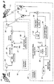
- Aircraft segment 18 includes a conventional GPS receiver 22 for receiving GPS signals from a GPS satellite 24 via an antenna 25.
- GPS receiver 22 sends a position signal to a conventional Extended Kalman-Filter (EKF) 26 which tracks the position signal as a state vector.
- EKF 26 An optional input 27 to EKF 26 is a signal from an Inertial Navigation System (INS), such as a conventional mechanical gyro system which monitors the distance traveled by aircraft 12 from a predetermined position.
- INS Inertial Navigation System
- Aircraft 12 receives ranging signals from communication satellites 11 and stationary ground radar 13 via a second antenna 28.
- Second antenna 28 is preferably a retrodirective antenna implemented with a Butler matrix, a low-profile digital beam former, and Wavelet-based Finite-Impulse-Response (WFIR) signal processing.
- the retrodirective antenna measures the direction of the received signal from communication satellite 11 and stationary ground radar 13 and automatically transmits the return signal back accordingly.
- the Butler matrix implements a Fourier transform forming a set of nearly orthogonal beams covering the field-of-view and is a relatively inexpensive approach to realizing a retrodirective antenna.
- the low-profile digital beam former array lends itself to a thin conformal array configuration which is preferred for aircraft installation.
- a tracking antenna can be used in place of the retrodirective antenna which consists of either an electronically or mechanically steered antenna driven by a monopulse, step-scanned, or conically-scanned tracking loop.
- a digital implementation of the Butler matrix is also required, such as a conjugate gradient digital beam former, in order to memorize the phase gradients of signals from various communication satellites 11, i.e, the direction of the incoming signals, and to apply proper phase conjugations to the outgoing signals so that the outgoing signals are directed to appropriate communication satellites 11.
- the data between aircraft segment 18 and ground segment 20 can be combined with the unique ranging code signal in one of several ways: 1) Overlaying a Auslander-Barbano (AB) Code Division Multiple Access (CDMA) tracking code on the communication link channels as low-level Additive White Gaussian Noise (AWGN), thermal noise-like signals which slightly raise the thermal noise floor; 2) Modulating the communication data with the AB CDMA ranging code and sent as a single waveform, as shown in Figure 3; and 3) Separating the ranging links from data links.
- ATC facility 16 transmits data which is modulated by a WFIR waveform with a unique AB ranging code assigned to each aircraft being tracked in the particular time slot.
- the waveform specifically provides a means to transmit a relatively wide-band WFIR ranging waveform over a group of narrow-band communication satellite channels, simultaneously or sequentially, and supports simultaneous ranging/doppler measurements and data demodulation.
- the two-way ranging data 30 is sent to ground segment 20 via stationary ground radar 13 and satellite ground station 14.
- Two-way ranging data 30 is used to drive a dual alpha-beta ( ⁇ - ⁇ )/EKF tracking loop 32 wherein the fast ⁇ - ⁇ loop tracks the AB CDMA code in communication coordinates, and the slow EKF tracks the target aircraft in Earth Centered Inertial (ECI) coordinates to provide a unique preferred tracking architecture with low-complexity, high accuracy, and high integrity with fast-response valid-track metrics, and the ability to track out total-electron-content (TEC) induced waveform transmission range and doppler offsets.
- ECI Earth Centered Inertial
- the ⁇ - ⁇ loop is a relatively fast pair of time and frequency tracking loops which measure and smooth the received two-way ranging signals during each access.
- the four dimensional state vector Z for the ⁇ - ⁇ loop consists of the timing offset, time drift, frequency offset and frequency drift.
- Time drift refers to clock drift whereas frequency offset refers to doppler shift due to link motion plus TEC.
- the state vector X for the EKF loop has eleven components consisting of the three-dimensional ECI position coordinates, velocity, acceleration, and the ranging plus doppler coordinates associated with ionospherical TEC effects.
- the EFK loop predicts ahead its state X k at the state transition time k*T, where T is the update interval for the EKF. This state is mapped into the corresponding predicted state Z k of the ⁇ - ⁇ loop.
- the ⁇ - ⁇ loop generates a smoothed state Z k which is then used by the EKF to smooth the predicted state to generate the smoothed state X k . This allows the EKF to predict ahead the state X k+1 at (k+1)*T . This procedure is repeated for the next access.
- the predicted state vector from the dual ⁇ - ⁇ /EKF tracking loop 32 and the estimated state vector 34 from aircraft 12 are transmitted to a fusion processor 36 which performs data fusion and validation between the two independent measurements to obtain an improved state vector estimation.
- Fusion processor 36 also receives other terrestrial based data 37, such as position of stationary ground radar 13, position of satellite ground station 14, and position of communication satellites 11.
- the improved state vector estimation is forwarded to ATC facility 16 which then transmits this information to aircraft 12.
- the improved state vector estimation 38 received by aircraft 12 is processed by EKF 26 to generate a new state vector.
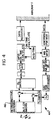
- Satellite ground station 14 transmits data which is modulated by a wavelet-based finite impulse response (WFIR) waveform with a unique AB ranging code assigned to each aircraft 12 being tracked in the access time slot.
- the TDMA data to the targeted aircraft is modulated by the N-chip AB code sequence, unsampled by the WFIR sample rate M, and added with signals to other aircraft sharing the same access slot.
- the summed output is filtered by a wideband WFIR filter with overlaid envelope of the AB ranging waveforms.
- a bank of narrowband WFIR filters channelizes the wideband waveform into a set of narrowband waveforms which are compatible with the satellite communication channels such as ICO.
- the receive processing at satellite ground station 14 is shown at 42.
- the baseband signal from the digitizer shown as an analog-to-digital (A/D) function and an in-phase-quadrature (I/Q) function which may be combined is detected by a bank of narrowband (NB) WFIR filters matched to the ICO communication channels.
- the outputs are used to perform reconstruction of the wideband WFIR ranging signal for each aircraft.
- This reconstructed wideband WFIR waveform is then detected by on-time, early, and late correlators.
- the ranging time and data from each aircraft is recovered by separate processing which performs the AB CDMA despreading, acquisition, tracking, time recovery, and data recovery.
- the aircraft receiver/transmitter 44 preferably includes a retrodirective antenna 46.
- a Butler matrix, low profile digital beam form (DBF), and WFIR signal processing are preferably employed.
- the retrodirective antenna 46 measures the direction of the received signal from the satellite 11, and automatically transmits the return signal back to the appropriate satellite 11.
- the Butler matrix implements a Fourier transform forming a set of nearly orthogonal beams covering the field of view, and has been proven to be a relatively inexpensive approach to realize a retrodirective antenna.
- the low profile DBF array lends itself to a thin conformal array configuration which is preferred for aircraft installation.
- the implementation technique eliminates the need for an expensive tracking antenna on the aircraft which usually consists of either an electronically or a mechanically steered antenna driven by a monopulse, step-scanned, or conically-scanned tracking loop.
- the principles of the present invention are utilized by an aircraft in a final approach and landing phase.
- the method and system can be extended to air space having a high density of traffic and covered by existing S-band secondary surveillance radars.
- the present invention compliments ADS techniques based on Global Navigation Satellite System (GNSS) using GPS and/or Glonass systems.
- GNSS Global Navigation Satellite System
- this invention will function without ADS.
Abstract
Description
Claims (10)
- A method for determining a position of an object utilizing two-way ranging, comprising the steps of:transmitting a first ranging signal from a first known location (13) on ground to the object (12);transmitting a second ranging signal to the first known ground location (13) in response to the first ranging signal;transmitting a third ranging signal to one of the object (12) and a second known location different from the first known ground location (13) in response to the first ranging signal;transmitting a fourth ranging signal to one of the object (12) and a third known location different from the first known ground location (13) and the second known location in response to the first ranging signal;determining a first delay corresponding to a time difference between transmission of the first ranging signal and receipt of the second ranging signal;determining a second delay based on the third ranging signal;determining a third delay based on the fourth ranging signal; anddetermining the position of the object (12) based on the first, second, and third known locations and the first, second and third delays.
- The method of claim 1, characterized in that transmitting the third ranging signal includes transmitting the third ranging signal to the second known location, wherein transmitting the fourth ranging signal includes transmitting the fourth ranging signal to the third known location, wherein determining the second delay includes determining the second delay corresponding to a time difference between transmission of the first ranging signal and receipt of the third ranging signal, and wherein determining the third delay includes determining the third delay corresponding to a time difference between transmission of the first ranging signal and receipt of the fourth ranging signal.
- The method of claim 1, characterized in that transmitting the third ranging signal includes transmitting the third ranging signal to the object (12) and in that transmitting the fourth ranging signal includes transmitting the fourth ranging signal to the object (12), the method further comprising:transmitting a fifth ranging signal to one of the first known ground location (13) and the second known location from the object (12) in response to the third ranging signal; andtransmitting a sixth ranging signal to one of the first known ground location (13) and the third known location from the object (12) in response to the fourth ranging signal.
- The method of claim 3, characterized in that transmitting the fifth ranging signal includes transmitting the fifth ranging signal to the first known ground location (13) and in that transmitting the sixth ranging signal includes transmitting the sixth ranging signal to the first known ground location (13).
- The method of claim 3, characterized in that transmitting the fifth ranging signal includes transmitting the fifth ranging signal to the second known location and in that transmitting the sixth ranging signal includes transmitting the sixth ranging signal to the third known location.
- A system for determining a position of an object (12) utilizing two-way ranging, comprising:a ground transceiver (13) at a first known location for providing a first bidirectional communication path between the ground transceiver (13) and the object (12) wherein the ground transceiver (13) transmits a first ranging signal to the object (12) and the object (12) transmits a second ranging signal to the ground receiver (13) in response to the first ranging signal;a first communication transceiver (11) at a second known location for providing one of a second bidirectional communication path (R3) and a first unidirectional communication path between the first communication transceiver (11) and the object (12) wherein the first communication transceiver (11) performs one of transmitting a third ranging signal to the object (12) and receiving a third ranging signal from the object (12) in response to the first ranging signal;a second communication transceiver (11) at a third known location for providing one of a third bidirectional communication (R4) and a second unidirectional communication path between the second communication transceiver (11) and the object (12) wherein the second communication transceiver (11) performs one of transmitting a fourth ranging signal to the object (12) and receiving a fourth ranging signal from the object (12) in response to the first ranging signal; anda signal processor (13, 14, 16) for determining a first path length based on the first bidirectional communication paths (R3), determining a second path length based on one of the second bidirectional communication path (R4) and first unidirectional communication path, determining a third path length based on one of the third bidirectional communication path and second unidirectional communication path, and determining the position of the object (12) based on the first, second and third known locations and the first, second and third path lengths.
- The system of claim 6, characterized in that the first communication transceiver (11) provides the first unidirectional communication path (R3) from the object (12) to the first communication transceiver (11) so that the object (12) transmits the third ranging signal to the first communication transceiver (11) in response to the first ranging signal and in that the second communication transceiver (11) provides the second unidirectional communication path (R4) from the object (12) to the second communication transceiver (11) so that the object (12) transmits the fourth ranging signal to the second communication transceiver (11) in response to the first ranging signal.
- The system of claim 6, characterized in that the first communication transceiver (11) provides the first unidirectional communication path (R3) from the first communication transceiver (11) to the object (12) so that the first communication transceiver (11) transmits the third ranging signal to the object (12) and the object (12) transmits a fifth ranging signal to the ground transceiver (13) in response to the third ranging signal and in that the second communication transceiver (11) provides the second unidirectional communication path (R4) from the second communication transceiver (11) to the object (12) so that the second communication transceiver (11) transmits the fourth ranging signal to the object (12) and the object (12) transmits a sixth ranging signal to the ground transceiver (130) in response to the fourth ranging signal.
- The system of claim 6, characterized in that the first communication transceiver (11) provides the second bidirectional communication path between the first communication transceiver (11) and the object (12) so that the first communication transceiver (11) transmits the third ranging signal to the object (12) and the object (12) transmits a fifth ranging signal to the first communication transceiver (11) in response to the third ranging signal and in that the second communication transceiver (11) provides the third bidirectional communication path between the second communication transceiver (11) and the object (12) so that the second communication transceiver (11) transmits the fourth ranging signal to the object (12) and the object (12) transmits a sixth ranging signal to the second communication transceiver (11) in response to the fourth ranging signal.
- The system of claim 6, characterized in that the object (12) is an aircraft.
Applications Claiming Priority (2)
| Application Number | Priority Date | Filing Date | Title |
|---|---|---|---|
| US80393597A | 1997-02-21 | 1997-02-21 | |
| US803935 | 1997-02-21 |
Publications (3)
| Publication Number | Publication Date |
|---|---|
| EP0860708A2 true EP0860708A2 (en) | 1998-08-26 |
| EP0860708A3 EP0860708A3 (en) | 1999-09-29 |
| EP0860708B1 EP0860708B1 (en) | 2005-07-27 |
Family
ID=25187800
Family Applications (1)
| Application Number | Title | Priority Date | Filing Date |
|---|---|---|---|
| EP98103057A Expired - Lifetime EP0860708B1 (en) | 1997-02-21 | 1998-02-21 | Method and system for determining a position of a transceiver unit utilizing two-way ranging in a polystatic satellite configuration including a ground radar |
Country Status (3)
| Country | Link |
|---|---|
| US (1) | US6340947B1 (en) |
| EP (1) | EP0860708B1 (en) |
| DE (1) | DE69830936T2 (en) |
Cited By (14)
| Publication number | Priority date | Publication date | Assignee | Title |
|---|---|---|---|---|
| EP1010988A2 (en) * | 1998-12-10 | 2000-06-21 | Hughes Electronics Corporation | Method and system for incorporating two-way ranging navigation as a calibration reference for GPS |
| EP1022580A2 (en) * | 1999-01-21 | 2000-07-26 | Associazione Vito Volterra | Landing assistance system |
| US6563457B2 (en) | 1997-02-21 | 2003-05-13 | Hughes Electronics Corporation | Method and system for determining a position of an object using two-way ranging in a polystatic satellite configuration |
| GB2382481A (en) * | 2001-07-26 | 2003-05-28 | Codar Ocean Sensors Ltd | Ocean surface current mapping with a bi-static radar system |
| US6920309B1 (en) | 1999-03-18 | 2005-07-19 | The Directv Group, Inc. | User positioning technique for multi-platform communication system |
| US6941107B2 (en) | 2001-01-19 | 2005-09-06 | The Directv Group, Inc. | Stratospheric platform based surface vehicle tracking and mobile data network |
| US6963548B1 (en) | 2000-04-17 | 2005-11-08 | The Directv Group, Inc. | Coherent synchronization of code division multiple access signals |
| US6990314B1 (en) | 1999-03-18 | 2006-01-24 | The Directv Group, Inc. | Multi-node point-to-point satellite communication system employing multiple geo satellites |
| US7089000B1 (en) | 1999-03-18 | 2006-08-08 | The Directv Group, Inc. | Multi-node wireless communication system with multiple transponding platforms |
| US7257418B1 (en) | 2000-08-31 | 2007-08-14 | The Directv Group, Inc. | Rapid user acquisition by a ground-based beamformer |
| EP2330441A1 (en) * | 2006-05-18 | 2011-06-08 | The Boeing Company | Generalized High Performance Navigation System |
| CN106656298A (en) * | 2016-11-16 | 2017-05-10 | 航天恒星科技有限公司 | Communication link planning method and system |
| CN111562595A (en) * | 2020-05-19 | 2020-08-21 | 中国科学院微小卫星创新研究院 | Satellite autonomous positioning and time synchronization system and method |
| CN113794497A (en) * | 2021-08-24 | 2021-12-14 | 西安大衡天成信息科技有限公司 | Mobile satellite communication antenna terminal with anti-interference positioning function |
Families Citing this family (38)
| Publication number | Priority date | Publication date | Assignee | Title |
|---|---|---|---|---|
| US6700939B1 (en) * | 1997-12-12 | 2004-03-02 | Xtremespectrum, Inc. | Ultra wide bandwidth spread-spectrum communications system |
| US6337980B1 (en) | 1999-03-18 | 2002-01-08 | Hughes Electronics Corporation | Multiple satellite mobile communications method and apparatus for hand-held terminals |
| US6785553B2 (en) | 1998-12-10 | 2004-08-31 | The Directv Group, Inc. | Position location of multiple transponding platforms and users using two-way ranging as a calibration reference for GPS |
| US7346120B2 (en) * | 1998-12-11 | 2008-03-18 | Freescale Semiconductor Inc. | Method and system for performing distance measuring and direction finding using ultrawide bandwidth transmissions |
| US7667647B2 (en) * | 1999-03-05 | 2010-02-23 | Era Systems Corporation | Extension of aircraft tracking and positive identification from movement areas into non-movement areas |
| US7777675B2 (en) * | 1999-03-05 | 2010-08-17 | Era Systems Corporation | Deployable passive broadband aircraft tracking |
| US20100079342A1 (en) * | 1999-03-05 | 2010-04-01 | Smith Alexander E | Multilateration enhancements for noise and operations management |
| US7782256B2 (en) * | 1999-03-05 | 2010-08-24 | Era Systems Corporation | Enhanced passive coherent location techniques to track and identify UAVs, UCAVs, MAVs, and other objects |
| US8203486B1 (en) | 1999-03-05 | 2012-06-19 | Omnipol A.S. | Transmitter independent techniques to extend the performance of passive coherent location |
| US7908077B2 (en) * | 2003-06-10 | 2011-03-15 | Itt Manufacturing Enterprises, Inc. | Land use compatibility planning software |
| US7739167B2 (en) | 1999-03-05 | 2010-06-15 | Era Systems Corporation | Automated management of airport revenues |
| US7570214B2 (en) | 1999-03-05 | 2009-08-04 | Era Systems, Inc. | Method and apparatus for ADS-B validation, active and passive multilateration, and elliptical surviellance |
| US7889133B2 (en) | 1999-03-05 | 2011-02-15 | Itt Manufacturing Enterprises, Inc. | Multilateration enhancements for noise and operations management |
| US8446321B2 (en) | 1999-03-05 | 2013-05-21 | Omnipol A.S. | Deployable intelligence and tracking system for homeland security and search and rescue |
| US6763242B1 (en) | 2000-09-14 | 2004-07-13 | The Directv Group, Inc. | Resource assignment system and method for determining the same |
| US7489927B2 (en) * | 2002-05-24 | 2009-02-10 | Alcatel-Lucent Usa Inc. | Method and system for object tracking and communication |
| US7183969B2 (en) | 2004-12-22 | 2007-02-27 | Raytheon Company | System and technique for calibrating radar arrays |
| US7633427B2 (en) * | 2005-10-20 | 2009-12-15 | Kinetx, Inc. | Active imaging using satellite communication system |
| US7965227B2 (en) * | 2006-05-08 | 2011-06-21 | Era Systems, Inc. | Aircraft tracking using low cost tagging as a discriminator |
| US8296051B2 (en) * | 2006-05-18 | 2012-10-23 | The Boeing Company | Generalized high performance navigation system |
| US7554481B2 (en) * | 2006-05-18 | 2009-06-30 | The Boeing Company | Localized jamming of navigation signals |
| US7579987B2 (en) * | 2006-05-18 | 2009-08-25 | The Boeing Company | Low earth orbit satellite providing navigation signals |
| US7583225B2 (en) * | 2006-05-18 | 2009-09-01 | The Boeing Company | Low earth orbit satellite data uplink |
| US8090312B2 (en) * | 2006-10-03 | 2012-01-03 | Raytheon Company | System and method for observing a satellite using a satellite in retrograde orbit |
| US7834807B2 (en) * | 2007-05-21 | 2010-11-16 | Spatial Digital Systems, Inc. | Retro-directive ground-terminal antenna for communication with geostationary satellites in slightly inclined orbits |
| US8035558B2 (en) * | 2008-05-30 | 2011-10-11 | The Boeing Company | Precise absolute time transfer from a satellite system |
| US8542147B2 (en) | 2008-05-30 | 2013-09-24 | The Boeing Company | Precise absolute time transfer from a satellite system |
| US7952518B2 (en) | 2008-05-30 | 2011-05-31 | The Boeing Company | Internet hotspots localization using satellite systems |
| US7859455B2 (en) * | 2009-01-06 | 2010-12-28 | The Boeing Company | Local clock frequency calibration using low earth orbit (LEO) satellites |
| US8024069B2 (en) * | 2009-01-28 | 2011-09-20 | Ge Intelligent Platforms, Inc. | System and method for path planning |
| DE102010041675B4 (en) * | 2010-09-29 | 2017-07-06 | Siemens Aktiengesellschaft | High-precision time synchronization of network participants |
| US8693947B2 (en) * | 2011-05-27 | 2014-04-08 | John F. SILNY | Extensible high bandwidth global space communication network |
| DK2950116T3 (en) * | 2014-05-28 | 2019-06-24 | Diehl Defence Gmbh & Co Kg | PROCEDURE FOR DETERMINING IN THE LOWEST ATTENTION OF AN AIRPORT AND / OR IN THE MINIMUM OF A PROPERTY AT THE OBJECT AND THE ORDERED DETECTOR DETECTOR |
| JP6696723B2 (en) * | 2014-10-21 | 2020-05-20 | 株式会社小松製作所 | Position measuring system and speed measuring system |
| FR3030057B1 (en) * | 2014-12-12 | 2017-01-27 | Thales Sa | METHOD AND SYSTEM FOR VALIDATION OF SATELLITE GEOLOCATION |
| US10254392B2 (en) | 2015-09-09 | 2019-04-09 | The United States Of America As Represented By The Secretary Of The Navy | Reverse-ephemeris method for determining position, attitude, and time |
| US10330794B2 (en) * | 2016-04-04 | 2019-06-25 | Spire Global, Inc. | AIS spoofing and dark-target detection methodology |
| US11650307B2 (en) * | 2020-06-02 | 2023-05-16 | Cypress Semiconductor Corporation | Agile interference detection and mitigation for multicarrier phase ranging systems |
Citations (4)
| Publication number | Priority date | Publication date | Assignee | Title |
|---|---|---|---|---|
| US4359733A (en) * | 1980-09-23 | 1982-11-16 | Neill Gerard K O | Satellite-based vehicle position determining system |
| EP0335558A2 (en) * | 1988-03-26 | 1989-10-04 | The Marconi Company Limited | Radio communication system |
| US4897661A (en) * | 1987-04-10 | 1990-01-30 | Sony Corporation | Method and apparatus for determining the position of a vehicle |
| US5006855A (en) * | 1986-08-20 | 1991-04-09 | The Mitre Corporation | Ranging and processing system for mobile surveillance and data link |
Family Cites Families (31)
| Publication number | Priority date | Publication date | Assignee | Title |
|---|---|---|---|---|
| US2470787A (en) | 1944-05-04 | 1949-05-24 | Paul W Nosker | System for determining the position or path of an object in space |
| US2763857A (en) * | 1945-11-15 | 1956-09-18 | Jr George E Valley | Two station navigation system |
| US2821704A (en) * | 1945-11-30 | 1958-01-28 | Marcus D O'day | Navigation system |
| US3384891A (en) | 1965-02-11 | 1968-05-21 | Gen Electric | Method and system for long distance navigation and communication |
| DE1591517B1 (en) | 1967-07-21 | 1971-08-05 | Siemens Ag | Radio location method by measuring the transit time to vehicles with transponders via earth satellites |
| US3665464A (en) * | 1969-05-01 | 1972-05-23 | Goodyear Aerospace Corp | Method and apparatus for high speed vehicle position acquisition |
| US3668403A (en) * | 1969-05-05 | 1972-06-06 | Goodyear Aerospace Corp | Method and apparatus for vehicle traffic control |
| US4161734A (en) | 1977-10-17 | 1979-07-17 | General Electric Company | Position surveillance using one active ranging satellite and time of arrival of a signal from an independent satellite |
| US4161730A (en) | 1977-10-17 | 1979-07-17 | General Electric Company | Radio determination using satellites transmitting timing signals with correction by active range measurement |
| DE3301613A1 (en) | 1983-01-19 | 1984-07-19 | Standard Elektrik Lorenz Ag, 7000 Stuttgart | POSITION DETECTION SYSTEM |
| US5099245A (en) | 1987-10-23 | 1992-03-24 | Hughes Aircraft Company | Vehicle location system accuracy enhancement for airborne vehicles |
| JPH0228580A (en) | 1988-07-18 | 1990-01-30 | Mitsubishi Electric Corp | Satellite tracking system |
| US5126748A (en) | 1989-12-05 | 1992-06-30 | Qualcomm Incorporated | Dual satellite navigation system and method |
| US4994809A (en) | 1990-03-07 | 1991-02-19 | Hughes Aircraft Company | Polystatic correlating radar |
| JPH03291584A (en) | 1990-04-10 | 1991-12-20 | Toyota Motor Corp | Navigation device for vehicle |
| JP2979582B2 (en) | 1990-05-23 | 1999-11-15 | ソニー株式会社 | Transmission system |
| US5387916A (en) | 1992-07-31 | 1995-02-07 | Westinghouse Electric Corporation | Automotive navigation system and method |
| US5430657A (en) | 1992-10-20 | 1995-07-04 | Caterpillar Inc. | Method and apparatus for predicting the position of a satellite in a satellite based navigation system |
| US5739785A (en) | 1993-03-04 | 1998-04-14 | Trimble Navigation Limited | Location and generation of high accuracy survey control marks using satellites |
| US5444450A (en) | 1993-08-11 | 1995-08-22 | Motorola, Inc. | Radio telecommunications system and method with adaptive location determination convergence |
| JP3269229B2 (en) | 1993-11-19 | 2002-03-25 | 株式会社デンソー | Mobile station location management system |
| US5410314A (en) | 1993-11-30 | 1995-04-25 | University Corporation For Atmospheric Research | Bistatic multiple-doppler radar network |
| JP2848249B2 (en) | 1994-06-28 | 1999-01-20 | 日本電気株式会社 | Aircraft position assessment system in landing guidance |
| US5525995A (en) | 1995-06-07 | 1996-06-11 | Loral Federal Systems Company | Doppler detection system for determining initial position of a maneuvering target |
| JPH0926328A (en) | 1995-07-12 | 1997-01-28 | Tokimec Inc | Position determination apparatus |
| JP3651504B2 (en) | 1995-10-17 | 2005-05-25 | 株式会社エクォス・リサーチ | Portable navigation device and in-vehicle navigation device |
| GB2306827B (en) | 1995-10-24 | 2000-05-31 | Int Mobile Satellite Org | Satellite radiodetermination |
| US5812961A (en) | 1995-12-28 | 1998-09-22 | Trimble Navigation Limited | Method and reciever using a low earth orbiting satellite signal to augment the global positioning system |
| US5945948A (en) | 1996-09-03 | 1999-08-31 | Motorola, Inc. | Method and apparatus for location finding in a communication system |
| JP3288586B2 (en) | 1996-09-19 | 2002-06-04 | シャープ株式会社 | DGPS receiver and DGPS positioning system |
| US5969674A (en) | 1997-02-21 | 1999-10-19 | Von Der Embse; Urban A. | Method and system for determining a position of a target vehicle utilizing two-way ranging |
-
1998
- 1998-02-21 EP EP98103057A patent/EP0860708B1/en not_active Expired - Lifetime
- 1998-02-21 DE DE69830936T patent/DE69830936T2/en not_active Expired - Lifetime
-
2000
- 2000-12-22 US US09/746,997 patent/US6340947B1/en not_active Expired - Lifetime
Patent Citations (4)
| Publication number | Priority date | Publication date | Assignee | Title |
|---|---|---|---|---|
| US4359733A (en) * | 1980-09-23 | 1982-11-16 | Neill Gerard K O | Satellite-based vehicle position determining system |
| US5006855A (en) * | 1986-08-20 | 1991-04-09 | The Mitre Corporation | Ranging and processing system for mobile surveillance and data link |
| US4897661A (en) * | 1987-04-10 | 1990-01-30 | Sony Corporation | Method and apparatus for determining the position of a vehicle |
| EP0335558A2 (en) * | 1988-03-26 | 1989-10-04 | The Marconi Company Limited | Radio communication system |
Cited By (19)
| Publication number | Priority date | Publication date | Assignee | Title |
|---|---|---|---|---|
| US6563457B2 (en) | 1997-02-21 | 2003-05-13 | Hughes Electronics Corporation | Method and system for determining a position of an object using two-way ranging in a polystatic satellite configuration |
| EP1010988A2 (en) * | 1998-12-10 | 2000-06-21 | Hughes Electronics Corporation | Method and system for incorporating two-way ranging navigation as a calibration reference for GPS |
| EP1010988A3 (en) * | 1998-12-10 | 2002-02-13 | Hughes Electronics Corporation | Method and system for incorporating two-way ranging navigation as a calibration reference for GPS |
| EP1022580A2 (en) * | 1999-01-21 | 2000-07-26 | Associazione Vito Volterra | Landing assistance system |
| EP1022580A3 (en) * | 1999-01-21 | 2001-02-28 | Associazione Vito Volterra | Landing assistance system |
| US6920309B1 (en) | 1999-03-18 | 2005-07-19 | The Directv Group, Inc. | User positioning technique for multi-platform communication system |
| US7089000B1 (en) | 1999-03-18 | 2006-08-08 | The Directv Group, Inc. | Multi-node wireless communication system with multiple transponding platforms |
| US6990314B1 (en) | 1999-03-18 | 2006-01-24 | The Directv Group, Inc. | Multi-node point-to-point satellite communication system employing multiple geo satellites |
| US6963548B1 (en) | 2000-04-17 | 2005-11-08 | The Directv Group, Inc. | Coherent synchronization of code division multiple access signals |
| US7257418B1 (en) | 2000-08-31 | 2007-08-14 | The Directv Group, Inc. | Rapid user acquisition by a ground-based beamformer |
| US6941107B2 (en) | 2001-01-19 | 2005-09-06 | The Directv Group, Inc. | Stratospheric platform based surface vehicle tracking and mobile data network |
| US6774837B2 (en) | 2001-07-26 | 2004-08-10 | Codar Ocean Sensors, Ltd. | Ocean surface current mapping with bistatic HF radar |
| GB2382481A (en) * | 2001-07-26 | 2003-05-28 | Codar Ocean Sensors Ltd | Ocean surface current mapping with a bi-static radar system |
| GB2382481B (en) * | 2001-07-26 | 2004-09-29 | Codar Ocean Sensors Ltd | Ocean surface current mapping with bistatic HF radar |
| EP2330441A1 (en) * | 2006-05-18 | 2011-06-08 | The Boeing Company | Generalized High Performance Navigation System |
| CN106656298A (en) * | 2016-11-16 | 2017-05-10 | 航天恒星科技有限公司 | Communication link planning method and system |
| CN111562595A (en) * | 2020-05-19 | 2020-08-21 | 中国科学院微小卫星创新研究院 | Satellite autonomous positioning and time synchronization system and method |
| CN113794497A (en) * | 2021-08-24 | 2021-12-14 | 西安大衡天成信息科技有限公司 | Mobile satellite communication antenna terminal with anti-interference positioning function |
| CN113794497B (en) * | 2021-08-24 | 2023-02-28 | 西安大衡天成信息科技有限公司 | Mobile satellite communication antenna terminal with anti-interference positioning function |
Also Published As
| Publication number | Publication date |
|---|---|
| DE69830936D1 (en) | 2005-09-01 |
| EP0860708B1 (en) | 2005-07-27 |
| US20020003490A1 (en) | 2002-01-10 |
| DE69830936T2 (en) | 2006-04-20 |
| EP0860708A3 (en) | 1999-09-29 |
| US6340947B1 (en) | 2002-01-22 |
Similar Documents
| Publication | Publication Date | Title |
|---|---|---|
| EP0860708B1 (en) | Method and system for determining a position of a transceiver unit utilizing two-way ranging in a polystatic satellite configuration including a ground radar | |
| US6377208B2 (en) | Method and system for determining a position of a transceiver unit utilizing two-way ranging in a polystatic satellite configuration | |
| US5969674A (en) | Method and system for determining a position of a target vehicle utilizing two-way ranging | |
| US5438337A (en) | Navigation system using re-transmitted GPS | |
| US5126748A (en) | Dual satellite navigation system and method | |
| EP0504281B1 (en) | Dual satellite navigation method and system | |
| EP1010988B1 (en) | Method and system for incorporating two-way ranging navigation as a calibration reference for GPS | |
| JP3574929B2 (en) | Vector delay lock loop processing of wireless positioning transmitter signal | |
| US5467282A (en) | GPS and satellite navigation system | |
| US5570096A (en) | Method and system for tracking satellites to locate unknown transmitting accurately | |
| CA2066831C (en) | Vehicle tracking system employing global positioning system (gps) satellites | |
| US7098846B2 (en) | All-weather precision guidance and navigation system | |
| US7683832B2 (en) | Method for fusing multiple GPS measurement types into a weighted least squares solution | |
| Betz | Fundamentals of Satellite‐Based Navigation and Timing | |
| JP2711271B2 (en) | Positioning system by satellite | |
| Su | Precise orbit determination of global navigation satellite system of second generation (GNSS-2): orbit determination of IGSO, GEO and MEO satellites | |
| WO2020122852A1 (en) | Method for carrying out trajectory measurements (variants) and multi-positional phase system of trajectory measurements for realizing said method (variants) | |
| Fried | Operational benefits and design approaches for combining JTIDS and GPS navigation |
Legal Events
| Date | Code | Title | Description |
|---|---|---|---|
| PUAI | Public reference made under article 153(3) epc to a published international application that has entered the european phase |
Free format text: ORIGINAL CODE: 0009012 |
|
| AK | Designated contracting states |
Kind code of ref document: A2 Designated state(s): DE FR GB |
|
| AX | Request for extension of the european patent |
Free format text: AL;LT;LV;MK;RO;SI |
|
| PUAL | Search report despatched |
Free format text: ORIGINAL CODE: 0009013 |
|
| AK | Designated contracting states |
Kind code of ref document: A3 Designated state(s): AT BE CH DE DK ES FI FR GB GR IE IT LI LU MC NL PT SE |
|
| AX | Request for extension of the european patent |
Free format text: AL;LT;LV;MK;RO;SI |
|
| RIC1 | Information provided on ipc code assigned before grant |
Free format text: 6G 01S 5/02 A, 6G 01S 13/87 B |
|
| 17P | Request for examination filed |
Effective date: 20000324 |
|
| AKX | Designation fees paid |
Free format text: DE FR GB |
|
| 17Q | First examination report despatched |
Effective date: 20040602 |
|
| GRAP | Despatch of communication of intention to grant a patent |
Free format text: ORIGINAL CODE: EPIDOSNIGR1 |
|
| GRAS | Grant fee paid |
Free format text: ORIGINAL CODE: EPIDOSNIGR3 |
|
| GRAA | (expected) grant |
Free format text: ORIGINAL CODE: 0009210 |
|
| AK | Designated contracting states |
Kind code of ref document: B1 Designated state(s): DE FR GB |
|
| REG | Reference to a national code |
Ref country code: GB Ref legal event code: FG4D |
|
| REF | Corresponds to: |
Ref document number: 69830936 Country of ref document: DE Date of ref document: 20050901 Kind code of ref document: P |
|
| ET | Fr: translation filed | ||
| PLBE | No opposition filed within time limit |
Free format text: ORIGINAL CODE: 0009261 |
|
| STAA | Information on the status of an ep patent application or granted ep patent |
Free format text: STATUS: NO OPPOSITION FILED WITHIN TIME LIMIT |
|
| 26N | No opposition filed |
Effective date: 20060428 |
|
| REG | Reference to a national code |
Ref country code: FR Ref legal event code: PLFP Year of fee payment: 19 |
|
| REG | Reference to a national code |
Ref country code: FR Ref legal event code: PLFP Year of fee payment: 20 |
|
| PGFP | Annual fee paid to national office [announced via postgrant information from national office to epo] |
Ref country code: FR Payment date: 20170118 Year of fee payment: 20 Ref country code: DE Payment date: 20170227 Year of fee payment: 20 |
|
| PGFP | Annual fee paid to national office [announced via postgrant information from national office to epo] |
Ref country code: GB Payment date: 20170126 Year of fee payment: 20 |
|
| REG | Reference to a national code |
Ref country code: DE Ref legal event code: R071 Ref document number: 69830936 Country of ref document: DE |
|
| REG | Reference to a national code |
Ref country code: GB Ref legal event code: PE20 Expiry date: 20180220 |
|
| PG25 | Lapsed in a contracting state [announced via postgrant information from national office to epo] |
Ref country code: GB Free format text: LAPSE BECAUSE OF EXPIRATION OF PROTECTION Effective date: 20180220 |